EP3623075A2 - Dispositif de réglage pour le petit côté d'une lingotière de coulée continue et procédé de réglage du petit côté d'une lingotière de coulée continue - Google Patents
Dispositif de réglage pour le petit côté d'une lingotière de coulée continue et procédé de réglage du petit côté d'une lingotière de coulée continue Download PDFInfo
- Publication number
- EP3623075A2 EP3623075A2 EP19196387.5A EP19196387A EP3623075A2 EP 3623075 A2 EP3623075 A2 EP 3623075A2 EP 19196387 A EP19196387 A EP 19196387A EP 3623075 A2 EP3623075 A2 EP 3623075A2
- Authority
- EP
- European Patent Office
- Prior art keywords
- actuator
- narrow side
- mold
- length
- continuous casting
- Prior art date
- Legal status (The legal status is an assumption and is not a legal conclusion. Google has not performed a legal analysis and makes no representation as to the accuracy of the status listed.)
- Granted
Links
Images


Classifications
-
- B—PERFORMING OPERATIONS; TRANSPORTING
- B22—CASTING; POWDER METALLURGY
- B22D—CASTING OF METALS; CASTING OF OTHER SUBSTANCES BY THE SAME PROCESSES OR DEVICES
- B22D11/00—Continuous casting of metals, i.e. casting in indefinite lengths
- B22D11/04—Continuous casting of metals, i.e. casting in indefinite lengths into open-ended moulds
- B22D11/05—Continuous casting of metals, i.e. casting in indefinite lengths into open-ended moulds into moulds having adjustable walls
-
- B—PERFORMING OPERATIONS; TRANSPORTING
- B22—CASTING; POWDER METALLURGY
- B22D—CASTING OF METALS; CASTING OF OTHER SUBSTANCES BY THE SAME PROCESSES OR DEVICES
- B22D11/00—Continuous casting of metals, i.e. casting in indefinite lengths
- B22D11/16—Controlling or regulating processes or operations
- B22D11/168—Controlling or regulating processes or operations for adjusting the mould size or mould taper
Definitions
- the invention relates to an adjustment device for the narrow side of a continuous casting mold according to the preamble of claim 1, and a method for adjusting a narrow side of a continuous casting mold according to the preamble of claim 10.
- At least one narrow side of the mold can be adjusted relative to the other narrow side, or both narrow sides relative to one another, in order to set a different format for the casting strand.
- this is off DE 197 48 305 A1 or WO 2009/144127 A1 known - in these publications at least one narrow side of the mold is adjusted by a narrow side adjusting device or an adjusting element acting in this way, which is connected to the narrow side, for the purpose of adjusting the casting width.
- the individual positions of the axes along which the adjustment drives for a respective mold narrow side act can be converted into a side-related mold conicity and into an opening width of the mold (in different horizontal levels: top edge, bottom edge, Bath level) can be converted accordingly.
- the basis for calculating a nominal width in a continuous casting mold is the desired cold width of the cast strand format. From this value, a so-called temperature shrinkage factor is then used to convert the mold narrow side to the desired width setting (cold dimension to warm dimension in the mold). The same applies to the so-called mold taper. Such taper is required in continuous casting to compensate for the temperature shrinkage of the hot steel, i.e. Compensate for width shrinkage in the mold or above the height of the mold narrow side, alone within the given mold height.
- the mold narrow sides are set to the respective target values, and position changes for the mold narrow sides can also be made during the casting operation.
- Such process-dependent changes in the positions of the narrow sides serve for the desired changes in width, or also for the necessary adjustments (conicity and width) when the steel quality changes and / or when the casting speed changes.
- the position of the narrow sides of a continuous casting mold is regulated by the automation of the continuous casting plant.
- a setpoint for setting the Width synonymous with the position of the mold narrow sides, and the narrow side taper specified by the basic automation.
- the mold narrow sides are set to predetermined target values on the basis of a calibration of the measuring system of the narrow side adjusting device, this calibration being carried out before the start of casting, as a rule, at ambient temperature.
- the mechanical adjustment system is assumed to be a constant and unchangeable parameter in such a calibration.
- the object of the invention is to optimize the setting of the narrow sides of a mold in the continuous casting process with a view to a consistently high quality of products produced thereby and also to increase operational reliability.
- An adjusting device is used to adjust the narrow side of a continuous casting mold.
- the adjustment device includes at least one actuator, which is connected to the mold narrow side, in particular by means of a joint, and a control device for generating an actuating signal and for controlling the actuator with the actuating signal, whereby the mold narrow side is set in a desired position in the direction of a setting axis in the operation of a continuous casting installation can be.
- At least one temperature sensor is arranged on the actuator, on parts thereof and / or adjacent to the actuator, which is in signal connection with the control device, for example wired or wireless over a radio link or the like.
- the control device comprises a computing unit with which a temperature change for the actuator and / or parts thereof detected by the temperature sensor can be converted into a thermally induced change in length.
- the control device is set up in terms of program technology in such a way that this calculated change in length in the direction of the setting axis is used to determine a correction variable which is taken into account when the actuator is actuated with the control signal.
- the invention is based on the essential finding that during the continuous casting process, temperature changes occurring on the actuator, on parts thereof and / or adjacent to this actuator are recorded with at least one temperature sensor, these temperature changes then being length-wise or thermally caused by the computing unit of the control device Changes in length of the actuator or parts thereof that occur on the actuator and / or its components are converted. Taking into account these calculated changes in length, the invention then determines correction values which are suitably taken into account for the actuating signals with which an actuator for setting a mold narrow side into its target position is controlled. As a result, corrected adjustment paths are realized for an actuator connected to a mold narrow side, so that the length changes occurring as a result of temperature changes are suitably compensated for. As a result, a mold narrow side is set up again exactly according to the specifications of its target position. Thus, changing temperature conditions during continuous casting with the present invention no longer disadvantageously lead to an otherwise inaccurate adjustment of the narrow-side mold and / or its taper.
- the actuator with which an adjustment and / or adjustment of a mold narrow side takes place, can be formed from a hydraulic cylinder or from an electromotive spindle drive. Details of these possible embodiments of the actuator are explained below in another place.
- modified component lengths of the actuator can be determined which correspond to said calculated changes in length of the actuator or parts thereof.
- a change in length can occur on a quill tube or a spindle which is guided in a movable manner, a change in length on its cylinder rod being able to occur when a hydraulic cylinder is used.
- these changes in length are appropriately taken into account when actuating the actuator, so that when the mold narrow side is turned on, there are no deviations or inaccuracies in accordance with its target position, even when the temperatures in the casting operation fluctuate.
- thermo sensors can be used for the temperature measurement on the actuator of an adjusting device according to the invention, e.g. Thermal elements, semiconductor temperature sensors, integrated temperature sensors, fiber optic temperature sensors, NTC's, PTC's, and / or also infrared sensors.
- the above-mentioned correction of the adjustment paths for the actuator is to be understood such that if the thermal change in length of the actuator and / or parts thereof is positive or becomes larger, then this change in length from the adjustment path that otherwise with the actuator in the direction of the setting axis would be set, subtracted or subtracted.
- this change in length from the adjustment path that otherwise with the actuator in the direction of the setting axis would be set, subtracted or subtracted.
- a "shrinkage" of the actuator is then added to the adjustment path.
- This subtraction or addition takes place by means of a suitable correction value which is applied to the control signal with which the control element is controlled.
- a temperature sensor can be attached to the outside of a mold narrow side. This ensures that fluctuating temperatures, which occur during the continuous casting process inside the mold and also propagate on an actuator connected to a mold side or a part thereof, can be reliably detected or measured. In addition and / or alternatively, it is also possible for a temperature sensor to be arranged or accommodated in a mold narrow side, with the same advantages as just explained.
- a temperature sensor can also be integrated in a position transmitter of the adjustment device according to the invention, which is in signal connection with the control device. This is done with the proviso that such a position transmitter is arranged at least adjacent to the actuator or in its vicinity, or can also be attached to the actuator itself.
- the production of desired slab widths with possibly improved width tolerance is possible, even if temperature fluctuations should occur in the continuous casting process.
- casting disturbances can also be reduced effectively, which has an advantageous effect on increasing the production output.
- Fig. 1 shows parts of a continuous casting mold 12, namely a basically simplified side view of the narrow sides 11 thereof, which can be adjusted along pitch axes A in the direction of a center M of the continuous casting mold 12, or away therefrom.
- the mold narrow sides 11 are connected to actuators 14 on their outer sides by joints 16. How from Fig. 1 can be seen for each mold narrow side 11 two actuators 14 are provided, whose axes of engagement A run approximately parallel to one another and are arranged one above the other.
- uniform actuation of the two actuators 14 enables the mold narrow side 11 to move in the direction of the setting axes A, in order to thereby set the casting width for the continuous casting mold 12. If the two actuators 14 are each actuated differently from one another, this leads to a change in the inclination of a mold narrow side 11 with respect to the vertical, and thus to the adjustment of the taper of this mold narrow side 11.
- an adjustment device 10 which serves to adjust a mold narrow side 11.
- the 3 and 4 for simplification only one half of each, in the present case a mold narrow side 11 arranged on the right in comparison to that Fig. 1 and 2nd .
- an adjusting device 10 on a (in Fig. 3 respectively. Fig. 4 not shown) arranged on the left-hand mold narrow side 11 is identical.
- the adjusting device 10 comprises of Fig. 3 respectively.
- Fig. 4 One control device 18 each with a computing unit 19.
- This control device 18 can either be part of an automation system of a continuous casting installation (not shown), or vice versa: The automation of such a continuous casting installation is then integrated into this control unit 18 or a part thereof.
- the adjusting device 10 comprises two actuators 14, namely in the form of electromotive spindle drives 14-S, each of which is connected to an outside of the mold narrow side 11 via a joint 16.
- These spindle drives 14-S form an electromechanical concept for adjusting the mold narrow side 11 and are each arranged at the points in the Fig. 2 are referred to as "reference height of upper actuator” and "reference height of lower actuator”.
- a spindle drive 14-S each has a spindle 25 which is rotatably guided in a quill tube 26 connected to the joint 16 and is driven in rotation by a motor 27.
- the motor 27 of a respective spindle drive 14-S is equipped with a rotary encoder 28 which serves to determine the position of the spindle 25. This rotary encoder 28 is also connected to the control device 18 via a signal path 21.
- a rotation of the spindle 25 within the sleeve tube 26 realizes a variable spindle stroke length with which an adjustment of the mold narrow side 11 is achieved.
- the adjustment of a spindle drive 14-S takes place along a spindle stroke axis which in the Fig. 3 is designated as such and is symbolized by a double arrow.
- This spindle stroke axis corresponds to a pitch axis A, as in connection with Fig. 1 shown and explained.
- a temperature sensor 20 is attached to the quill tube 26 of a respective spindle 14-S and is also connected to the control device 18 via a signal path 21. The mode of operation of this temperature sensor 20 is explained separately below.
- the adjusting device 10 comprises two actuators 14, namely in the form of hydraulic cylinders 14-H, each of which is connected to an outside of the mold narrow side 11 via a joint 16.
- These hydraulic cylinders 14-H form a hydraulic concept for adjusting the mold narrow side 11 and are each arranged at the points in the Fig. 2 are referred to as "reference height of upper actuator” and "reference height of lower actuator”.
- a piston rod 23 leads to the joint 16 for the purpose of a connection to the mold narrow side 11.
- a temperature sensor 20 is attached to the piston rod 23, which - in the same way as in the embodiment of FIG Fig. 3 is connected to the control device 18 via a signal path 21.
- Each of the two hydraulic cylinders 14-H is equipped with a linear encoder 24, which is also connected to the control device 18 via a signal path 21. The position of a piston of any hydraulic cylinder 14-H is not possible by means of the linear encoder 24.
- a variable adjustment length is realized with which the piston rod 23 brings the mold narrow side 11 into position.
- the piston rod 23 is adjusted along a cylinder stroke axis, which corresponds to a setting axis A, as in connection with Fig. 1 shown and explained.
- temperature sensor 20 and / or the provision of further temperature sensors 20 are also possible, for example in or on the gearbox G of a spindle drive 14-S, in or on the motor 27, in or on the rotary encoder 28, in or on the housing 22 of a hydraulic cylinder 14-H, in or preferably on the linear encoder 24, and / or in or on the mold narrow side 11.
- the linear encoder 24 and the rotary encoder 28 can also be referred to collectively as a position encoder, in or on the, as just explained , the temperature sensor 20 can be attached.
- This also includes associated connecting elements and bearing housings of the individual actuators 14. A measured temperature can then be transmitted to the control device 18 and its computing unit 19 via the signal path 21.
- a casting strand which is discharged from the continuous casting mold 12 in a downward direction during operation of a continuous casting installation.
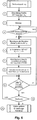
- step 1 of Fig. 6 Before starting a continuous casting process, appropriate preparations are made (see step 1 of Fig. 6 ). This includes, among other things, a calibration of the actuators 14-H or 14-S, which, as explained, with the mold narrow side 11 on their side Outside are connected. In this regard, it is assumed that such a calibration is carried out at a reference temperature of, for example, 20 ° C., this calibration temperature in the diagram of Fig. 6 is denoted by "T K ".
- the calibration mentioned also includes knowledge of the materials or materials that are used for the individual actuators.
- the respective material-dependent linear expansion coefficients ⁇ for the individual parts or materials from which an actuator 14 is or is formed are stored in the computing unit 19.
- an output length l 0 is stored in the computing unit 19, which - when using a spindle drive 14-S - a system consisting of the quill tube 26 and the spindle 25 rotatably guided therein, or - when using a hydraulic cylinder 14-H - a piston rod 23, at the calibration temperature T K.
- an output length l 0 is stored in the arithmetic unit 19, which an actuator 14 has with all parts thereof along its setting axis A at the calibration temperature T K.
- a next step 2 the setting of the continuous casting mold 12 is then carried out. This also includes that the two mold narrow sides 11 are brought into their desired position by actuating the respective actuators 14. This takes place in that a control signal S is generated by the control device 18 (in the 3 and 4 each symbolized by an arrow "S") with which the motor 27 of a spindle drive 14-S or the piston K of a hydraulic cylinder 14-H is controlled.
- step 3 after all the necessary preparations have been made, the continuous casting process starts.
- the operating temperature T B is measured by the temperature sensor (s) 20, which are present on the actuators 14, adjacent to this and / or on their parts, the temperature measured values then via the signal path 21 to the control device 18 and its computing unit 19 are transmitted.
- step 4 it is checked whether a predetermined casting length has already been reached.
- a predetermined casting length corresponds at least to the narrow side height H (cf. Fig. 2 ) the continuous casting mold, or preferably a multiple of this narrow side height H.
- a predetermined casting length can assume the value of 2 meters.
- a change in length along the adjustment axis A is determined in step 7 Fig. 6 a current actual position for a mold narrow side 11 is calculated, and then in the next step 8 according to Fig. 6 calculates a correction value "OFF-SET" which is applied to the control signal S output by the control device 18. In this way, the current position of a mold narrow side 11 can be set exactly to its target position even when temperature changes ⁇ T occur.
- the above-explained correction for setting up a mold narrow side 11 is illustrated using the following example: If, during the continuous casting process and after the predetermined casting length has been reached, the operating temperature T B on the spindle 25 of a spindle drive 14-S (cf. Fig. 3 ) or on the piston rod 23 of a hydraulic cylinder 14-H (cf. Fig. 4 ) increased compared to the calibration temperature T K , the joint position of a mold narrow side 11, to which this spindle drive 14-S or this hydraulic cylinder 14-H is connected, shifts in the direction of the mold center M as a result of a positive change in length. This change becomes then assigned to the spindle 25 or the piston rod 23 as an axial length "OFF-SET".
- step 7 a position of the actual positions of the mold narrow sides 11 is then new is calculated and the correction value "OFF-SET” is then determined in accordance with step 8, with which correction is then possible for the target positions at which the narrow sides are set by actuating the actuators 14.
- the correction value "OFF-SET” is subtracted or subtracted from the positive change in length which has occurred as a result of the increase in the operating temperature T B.
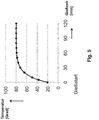
- FIG. 5 A typical temperature profile is shown, which is set for an actuator 14 on its setting axis A after the start of casting, ie after the start of a continuous casting process.
- steps shown here in particular steps 3-11, can be carried out automatically during the continuous casting process, without the intervention of operating personnel being necessary.
- the dominant component length for which there is a temperature dependency with respect to a change in length, is formed by the variable-acting spindle length, which is of different lengths depending on the engagement of the spindle 25 in the quill tube 26.
- the dominant component length in the electromechanical concept which must be taken into account to determine a possible change in length due to a change in the operating temperature T B , is variable and not constant, and thus represents the main length of the acting (variable) spindle stroke axis, which is used for the determination of the correction value "OFF-SET" is required.
- the cylinder rod of the piston rod 23 represents the dominant component length, which is subject to a temperature dependency with respect to a change in length, namely with an active length that extends from the piston K to the end of the piston rod 23 connected to the joint 16.
- the dominant component length in the form of the piston rod 23 is constant.
- the calculation of a possible temperature-related change in length is essentially based on the length of this piston rod 23, which corresponds to the length of the piston Fig. 4 illustrated "cylinder stroke axis" coincides, determined in order to determine the explained correction value "OFF-SET".
- the housing 22 of the hydraulic cylinder 14-H can also be included in the variable component length - in this case, a known position of the piston K and a known length of the housing 22 are added to a variable length component to be added along the adjustment axis A.
- the adjusting device 10 and the corresponding method according to the present invention By means of the adjusting device 10 and the corresponding method according to the present invention, not only the format width and the desired taper during the continuous casting process can be set for a mold narrow side 11, but also necessary corrections are made when starting the The mold narrow side 11 is made to the required target positions if there are changes in the operating temperature T B in the course of the continuous casting process and thus also a change in the length of the actuators 14 along an associated setting axis A. Such a correction also ensures that a concave or convex bulge on the narrow sides of the casting strand 13 is prevented during the continuous casting process.
Landscapes
- Engineering & Computer Science (AREA)
- Mechanical Engineering (AREA)
- Continuous Casting (AREA)
Applications Claiming Priority (1)
| Application Number | Priority Date | Filing Date | Title |
|---|---|---|---|
| DE102018215424.4A DE102018215424A1 (de) | 2018-09-11 | 2018-09-11 | Verstelleinrichtung für die Schmalseite einer Stranggießkokille, und Verfahren zum Verstellen einer Schmalseite einer Stranggießkokille |
Publications (3)
| Publication Number | Publication Date |
|---|---|
| EP3623075A2 true EP3623075A2 (fr) | 2020-03-18 |
| EP3623075A3 EP3623075A3 (fr) | 2020-05-13 |
| EP3623075B1 EP3623075B1 (fr) | 2020-12-23 |
Family
ID=68084574
Family Applications (1)
| Application Number | Title | Priority Date | Filing Date |
|---|---|---|---|
| EP19196387.5A Active EP3623075B1 (fr) | 2018-09-11 | 2019-09-10 | Dispositif de réglage pour le petit côté d'une lingotière de coulée continue et procédé de réglage du petit côté d'une lingotière de coulée continue |
Country Status (2)
| Country | Link |
|---|---|
| EP (1) | EP3623075B1 (fr) |
| DE (1) | DE102018215424A1 (fr) |
Cited By (2)
| Publication number | Priority date | Publication date | Assignee | Title |
|---|---|---|---|---|
| CN116197368A (zh) * | 2023-01-17 | 2023-06-02 | 中冶南方连铸技术工程有限责任公司 | 结晶器在线热调宽装置以及方法 |
| CN116237477A (zh) * | 2023-01-03 | 2023-06-09 | 飞马智科信息技术股份有限公司 | 一种结晶器宽度调节方法 |
Families Citing this family (1)
| Publication number | Priority date | Publication date | Assignee | Title |
|---|---|---|---|---|
| CN119114875A (zh) * | 2023-06-12 | 2024-12-13 | 宝山钢铁股份有限公司 | 一种板坯连铸机的定宽度开浇方法 |
Citations (2)
| Publication number | Priority date | Publication date | Assignee | Title |
|---|---|---|---|---|
| DE19748305A1 (de) | 1997-10-31 | 1999-05-06 | Schloemann Siemag Ag | Stranggießkokille |
| WO2009144127A1 (fr) | 2008-05-26 | 2009-12-03 | Siemens Vai Metals Technologies Gmbh & Co | Lingotière de coulée continue pour une installation de coulée continue |
Family Cites Families (1)
| Publication number | Priority date | Publication date | Assignee | Title |
|---|---|---|---|---|
| AT519154B1 (de) * | 2016-09-26 | 2019-12-15 | Primetals Technologies Austria GmbH | Regelung der Schmalseitenkonizität einer Stranggusskokille |
-
2018
- 2018-09-11 DE DE102018215424.4A patent/DE102018215424A1/de not_active Withdrawn
-
2019
- 2019-09-10 EP EP19196387.5A patent/EP3623075B1/fr active Active
Patent Citations (2)
| Publication number | Priority date | Publication date | Assignee | Title |
|---|---|---|---|---|
| DE19748305A1 (de) | 1997-10-31 | 1999-05-06 | Schloemann Siemag Ag | Stranggießkokille |
| WO2009144127A1 (fr) | 2008-05-26 | 2009-12-03 | Siemens Vai Metals Technologies Gmbh & Co | Lingotière de coulée continue pour une installation de coulée continue |
Cited By (2)
| Publication number | Priority date | Publication date | Assignee | Title |
|---|---|---|---|---|
| CN116237477A (zh) * | 2023-01-03 | 2023-06-09 | 飞马智科信息技术股份有限公司 | 一种结晶器宽度调节方法 |
| CN116197368A (zh) * | 2023-01-17 | 2023-06-02 | 中冶南方连铸技术工程有限责任公司 | 结晶器在线热调宽装置以及方法 |
Also Published As
| Publication number | Publication date |
|---|---|
| EP3623075B1 (fr) | 2020-12-23 |
| EP3623075A3 (fr) | 2020-05-13 |
| DE102018215424A1 (de) | 2020-03-12 |
Similar Documents
| Publication | Publication Date | Title |
|---|---|---|
| DE102013111257B3 (de) | Verfahren zur Prozessführung eines Formfüllvorgangs einer Spritzgießmaschine | |
| EP0813701B1 (fr) | Systeme de gestion pour installations de l'industrie primaire ou de l'industrie manufacturiere | |
| DE69508209T2 (de) | Verfahren zur Regelung des kontinuierlichen Giessens zwischen Walzen | |
| EP3623075B1 (fr) | Dispositif de réglage pour le petit côté d'une lingotière de coulée continue et procédé de réglage du petit côté d'une lingotière de coulée continue | |
| DE4040360A1 (de) | Regelung eines mehrgeruestigen warm- und/oder kaltband-walzwerks | |
| DE102008035639A1 (de) | Verfahren zur Modellierung eines Regelkreises für eine Bearbeitungsmaschine | |
| WO2004033167A1 (fr) | Procede et dispositif permettant de regler le repere de coupe d'une machine d'impression rotative a rouleaux | |
| DE2828151C2 (de) | Vorrichtung zur Steuerung der Lage wenigstens einer Profilwalze eines Walzgerüstes in Richtung der Walzenachse | |
| EP3173166B1 (fr) | Procédé et dispositif de réglage de la largeur d'une barre métallique coulée en continu | |
| EP3628416A1 (fr) | Procédé et installation de coulée continue d'un produit métallique | |
| CH638702A5 (de) | Einrichtung zur steuerung der formschliesskraft an einer kniehebelspritzgiessmaschine. | |
| WO2022106707A1 (fr) | Procédé de correction des propriétés d'une bande laminée à chaud ayant une composition chimique spécifique dans un laminoir à chaud | |
| EP2218629B1 (fr) | Véhicule doté d'une barre de connexion variable en longueur | |
| AT519390A1 (de) | Verfahren und Vorrichtung zum Regeln einer Stranggießanlage | |
| DE102017106559B4 (de) | Auslegung oder Durchführung einer Bewegungsaufgabe einer bewegten Masse in einer mechanischen Anlage entlang zumindest einer Bewegungsachse | |
| AT519154A1 (de) | Regelung der Schmalseitenkonizität einer Stranggusskokille | |
| EP1525061B1 (fr) | Correction dynamique d'epaisseur | |
| EP3336049A1 (fr) | Chariot de manutention pourvu d'une unité de commande permettant de régler le mouvement d'une charge ainsi que procédé correspondant | |
| EP1711283A1 (fr) | Procede de reglage et mecanisme de reglage pour une cage de laminoir | |
| EP2489445B1 (fr) | Dispositif doté d'une multitude d'installations de laminage à froid | |
| DE102011077454A1 (de) | Stranggießanlage | |
| DE102018213545A1 (de) | Strangführungssegment und Verfahren zu dessen Betrieb | |
| EP0775537A2 (fr) | Procédé pour la régulation de la section transversale d'un produit laminé | |
| DE3439459A1 (de) | Vorrichtung zur automatischen korrektur der position eines schlittens in einer presse | |
| DE212008000088U1 (de) | Fahrzeug, insbesondere Regalbediengerät |
Legal Events
| Date | Code | Title | Description |
|---|---|---|---|
| PUAI | Public reference made under article 153(3) epc to a published international application that has entered the european phase |
Free format text: ORIGINAL CODE: 0009012 |
|
| STAA | Information on the status of an ep patent application or granted ep patent |
Free format text: STATUS: REQUEST FOR EXAMINATION WAS MADE |
|
| 17P | Request for examination filed |
Effective date: 20190910 |
|
| AK | Designated contracting states |
Kind code of ref document: A2 Designated state(s): AL AT BE BG CH CY CZ DE DK EE ES FI FR GB GR HR HU IE IS IT LI LT LU LV MC MK MT NL NO PL PT RO RS SE SI SK SM TR |
|
| AX | Request for extension of the european patent |
Extension state: BA ME |
|
| PUAL | Search report despatched |
Free format text: ORIGINAL CODE: 0009013 |
|
| AK | Designated contracting states |
Kind code of ref document: A3 Designated state(s): AL AT BE BG CH CY CZ DE DK EE ES FI FR GB GR HR HU IE IS IT LI LT LU LV MC MK MT NL NO PL PT RO RS SE SI SK SM TR |
|
| AX | Request for extension of the european patent |
Extension state: BA ME |
|
| RIC1 | Information provided on ipc code assigned before grant |
Ipc: B22D 11/16 20060101ALI20200407BHEP Ipc: B22D 11/05 20060101AFI20200407BHEP |
|
| GRAP | Despatch of communication of intention to grant a patent |
Free format text: ORIGINAL CODE: EPIDOSNIGR1 |
|
| STAA | Information on the status of an ep patent application or granted ep patent |
Free format text: STATUS: GRANT OF PATENT IS INTENDED |
|
| INTG | Intention to grant announced |
Effective date: 20200713 |
|
| GRAS | Grant fee paid |
Free format text: ORIGINAL CODE: EPIDOSNIGR3 |
|
| GRAA | (expected) grant |
Free format text: ORIGINAL CODE: 0009210 |
|
| STAA | Information on the status of an ep patent application or granted ep patent |
Free format text: STATUS: THE PATENT HAS BEEN GRANTED |
|
| AK | Designated contracting states |
Kind code of ref document: B1 Designated state(s): AL AT BE BG CH CY CZ DE DK EE ES FI FR GB GR HR HU IE IS IT LI LT LU LV MC MK MT NL NO PL PT RO RS SE SI SK SM TR |
|
| RBV | Designated contracting states (corrected) |
Designated state(s): AL AT BE BG CH CY CZ DE DK EE ES FI FR GB GR HR HU IE IS IT LI LT LU LV MC MK MT NL NO PL PT RO RS SE SI SK SM TR |
|
| REG | Reference to a national code |
Ref country code: GB Ref legal event code: FG4D Free format text: NOT ENGLISH |
|
| REG | Reference to a national code |
Ref country code: DE Ref legal event code: R096 Ref document number: 502019000580 Country of ref document: DE |
|
| REG | Reference to a national code |
Ref country code: AT Ref legal event code: REF Ref document number: 1347246 Country of ref document: AT Kind code of ref document: T Effective date: 20210115 |
|
| REG | Reference to a national code |
Ref country code: IE Ref legal event code: FG4D Free format text: LANGUAGE OF EP DOCUMENT: GERMAN |
|
| PG25 | Lapsed in a contracting state [announced via postgrant information from national office to epo] |
Ref country code: FI Free format text: LAPSE BECAUSE OF FAILURE TO SUBMIT A TRANSLATION OF THE DESCRIPTION OR TO PAY THE FEE WITHIN THE PRESCRIBED TIME-LIMIT Effective date: 20201223 Ref country code: RS Free format text: LAPSE BECAUSE OF FAILURE TO SUBMIT A TRANSLATION OF THE DESCRIPTION OR TO PAY THE FEE WITHIN THE PRESCRIBED TIME-LIMIT Effective date: 20201223 Ref country code: NO Free format text: LAPSE BECAUSE OF FAILURE TO SUBMIT A TRANSLATION OF THE DESCRIPTION OR TO PAY THE FEE WITHIN THE PRESCRIBED TIME-LIMIT Effective date: 20210323 Ref country code: GR Free format text: LAPSE BECAUSE OF FAILURE TO SUBMIT A TRANSLATION OF THE DESCRIPTION OR TO PAY THE FEE WITHIN THE PRESCRIBED TIME-LIMIT Effective date: 20210324 |
|
| REG | Reference to a national code |
Ref country code: NL Ref legal event code: MP Effective date: 20201223 |
|
| PG25 | Lapsed in a contracting state [announced via postgrant information from national office to epo] |
Ref country code: LV Free format text: LAPSE BECAUSE OF FAILURE TO SUBMIT A TRANSLATION OF THE DESCRIPTION OR TO PAY THE FEE WITHIN THE PRESCRIBED TIME-LIMIT Effective date: 20201223 Ref country code: SE Free format text: LAPSE BECAUSE OF FAILURE TO SUBMIT A TRANSLATION OF THE DESCRIPTION OR TO PAY THE FEE WITHIN THE PRESCRIBED TIME-LIMIT Effective date: 20201223 Ref country code: BG Free format text: LAPSE BECAUSE OF FAILURE TO SUBMIT A TRANSLATION OF THE DESCRIPTION OR TO PAY THE FEE WITHIN THE PRESCRIBED TIME-LIMIT Effective date: 20210323 |
|
| PG25 | Lapsed in a contracting state [announced via postgrant information from national office to epo] |
Ref country code: NL Free format text: LAPSE BECAUSE OF FAILURE TO SUBMIT A TRANSLATION OF THE DESCRIPTION OR TO PAY THE FEE WITHIN THE PRESCRIBED TIME-LIMIT Effective date: 20201223 Ref country code: HR Free format text: LAPSE BECAUSE OF FAILURE TO SUBMIT A TRANSLATION OF THE DESCRIPTION OR TO PAY THE FEE WITHIN THE PRESCRIBED TIME-LIMIT Effective date: 20201223 |
|
| REG | Reference to a national code |
Ref country code: LT Ref legal event code: MG9D |
|
| PG25 | Lapsed in a contracting state [announced via postgrant information from national office to epo] |
Ref country code: SM Free format text: LAPSE BECAUSE OF FAILURE TO SUBMIT A TRANSLATION OF THE DESCRIPTION OR TO PAY THE FEE WITHIN THE PRESCRIBED TIME-LIMIT Effective date: 20201223 Ref country code: SK Free format text: LAPSE BECAUSE OF FAILURE TO SUBMIT A TRANSLATION OF THE DESCRIPTION OR TO PAY THE FEE WITHIN THE PRESCRIBED TIME-LIMIT Effective date: 20201223 Ref country code: EE Free format text: LAPSE BECAUSE OF FAILURE TO SUBMIT A TRANSLATION OF THE DESCRIPTION OR TO PAY THE FEE WITHIN THE PRESCRIBED TIME-LIMIT Effective date: 20201223 Ref country code: CZ Free format text: LAPSE BECAUSE OF FAILURE TO SUBMIT A TRANSLATION OF THE DESCRIPTION OR TO PAY THE FEE WITHIN THE PRESCRIBED TIME-LIMIT Effective date: 20201223 Ref country code: LT Free format text: LAPSE BECAUSE OF FAILURE TO SUBMIT A TRANSLATION OF THE DESCRIPTION OR TO PAY THE FEE WITHIN THE PRESCRIBED TIME-LIMIT Effective date: 20201223 Ref country code: RO Free format text: LAPSE BECAUSE OF FAILURE TO SUBMIT A TRANSLATION OF THE DESCRIPTION OR TO PAY THE FEE WITHIN THE PRESCRIBED TIME-LIMIT Effective date: 20201223 Ref country code: PT Free format text: LAPSE BECAUSE OF FAILURE TO SUBMIT A TRANSLATION OF THE DESCRIPTION OR TO PAY THE FEE WITHIN THE PRESCRIBED TIME-LIMIT Effective date: 20210423 |
|
| PG25 | Lapsed in a contracting state [announced via postgrant information from national office to epo] |
Ref country code: PL Free format text: LAPSE BECAUSE OF FAILURE TO SUBMIT A TRANSLATION OF THE DESCRIPTION OR TO PAY THE FEE WITHIN THE PRESCRIBED TIME-LIMIT Effective date: 20201223 |
|
| REG | Reference to a national code |
Ref country code: DE Ref legal event code: R097 Ref document number: 502019000580 Country of ref document: DE |
|
| PG25 | Lapsed in a contracting state [announced via postgrant information from national office to epo] |
Ref country code: IS Free format text: LAPSE BECAUSE OF FAILURE TO SUBMIT A TRANSLATION OF THE DESCRIPTION OR TO PAY THE FEE WITHIN THE PRESCRIBED TIME-LIMIT Effective date: 20210423 |
|
| PG25 | Lapsed in a contracting state [announced via postgrant information from national office to epo] |
Ref country code: AL Free format text: LAPSE BECAUSE OF FAILURE TO SUBMIT A TRANSLATION OF THE DESCRIPTION OR TO PAY THE FEE WITHIN THE PRESCRIBED TIME-LIMIT Effective date: 20201223 |
|
| PLBE | No opposition filed within time limit |
Free format text: ORIGINAL CODE: 0009261 |
|
| STAA | Information on the status of an ep patent application or granted ep patent |
Free format text: STATUS: NO OPPOSITION FILED WITHIN TIME LIMIT |
|
| PG25 | Lapsed in a contracting state [announced via postgrant information from national office to epo] |
Ref country code: DK Free format text: LAPSE BECAUSE OF FAILURE TO SUBMIT A TRANSLATION OF THE DESCRIPTION OR TO PAY THE FEE WITHIN THE PRESCRIBED TIME-LIMIT Effective date: 20201223 |
|
| 26N | No opposition filed |
Effective date: 20210924 |
|
| PG25 | Lapsed in a contracting state [announced via postgrant information from national office to epo] |
Ref country code: ES Free format text: LAPSE BECAUSE OF FAILURE TO SUBMIT A TRANSLATION OF THE DESCRIPTION OR TO PAY THE FEE WITHIN THE PRESCRIBED TIME-LIMIT Effective date: 20201223 |
|
| PG25 | Lapsed in a contracting state [announced via postgrant information from national office to epo] |
Ref country code: SI Free format text: LAPSE BECAUSE OF FAILURE TO SUBMIT A TRANSLATION OF THE DESCRIPTION OR TO PAY THE FEE WITHIN THE PRESCRIBED TIME-LIMIT Effective date: 20201223 |
|
| REG | Reference to a national code |
Ref country code: BE Ref legal event code: MM Effective date: 20210930 |
|
| PG25 | Lapsed in a contracting state [announced via postgrant information from national office to epo] |
Ref country code: IS Free format text: LAPSE BECAUSE OF FAILURE TO SUBMIT A TRANSLATION OF THE DESCRIPTION OR TO PAY THE FEE WITHIN THE PRESCRIBED TIME-LIMIT Effective date: 20210423 Ref country code: MC Free format text: LAPSE BECAUSE OF FAILURE TO SUBMIT A TRANSLATION OF THE DESCRIPTION OR TO PAY THE FEE WITHIN THE PRESCRIBED TIME-LIMIT Effective date: 20201223 |
|
| PG25 | Lapsed in a contracting state [announced via postgrant information from national office to epo] |
Ref country code: LU Free format text: LAPSE BECAUSE OF NON-PAYMENT OF DUE FEES Effective date: 20210910 Ref country code: IE Free format text: LAPSE BECAUSE OF NON-PAYMENT OF DUE FEES Effective date: 20210910 Ref country code: FR Free format text: LAPSE BECAUSE OF NON-PAYMENT OF DUE FEES Effective date: 20210930 Ref country code: BE Free format text: LAPSE BECAUSE OF NON-PAYMENT OF DUE FEES Effective date: 20210930 |
|
| REG | Reference to a national code |
Ref country code: CH Ref legal event code: PL |
|
| PG25 | Lapsed in a contracting state [announced via postgrant information from national office to epo] |
Ref country code: CY Free format text: LAPSE BECAUSE OF FAILURE TO SUBMIT A TRANSLATION OF THE DESCRIPTION OR TO PAY THE FEE WITHIN THE PRESCRIBED TIME-LIMIT Effective date: 20201223 |
|
| PG25 | Lapsed in a contracting state [announced via postgrant information from national office to epo] |
Ref country code: LI Free format text: LAPSE BECAUSE OF NON-PAYMENT OF DUE FEES Effective date: 20220930 Ref country code: HU Free format text: LAPSE BECAUSE OF FAILURE TO SUBMIT A TRANSLATION OF THE DESCRIPTION OR TO PAY THE FEE WITHIN THE PRESCRIBED TIME-LIMIT; INVALID AB INITIO Effective date: 20190910 Ref country code: CH Free format text: LAPSE BECAUSE OF NON-PAYMENT OF DUE FEES Effective date: 20220930 |
|
| P01 | Opt-out of the competence of the unified patent court (upc) registered |
Effective date: 20230707 |
|
| PG25 | Lapsed in a contracting state [announced via postgrant information from national office to epo] |
Ref country code: MK Free format text: LAPSE BECAUSE OF FAILURE TO SUBMIT A TRANSLATION OF THE DESCRIPTION OR TO PAY THE FEE WITHIN THE PRESCRIBED TIME-LIMIT Effective date: 20201223 |
|
| GBPC | Gb: european patent ceased through non-payment of renewal fee |
Effective date: 20230910 |
|
| PG25 | Lapsed in a contracting state [announced via postgrant information from national office to epo] |
Ref country code: GB Free format text: LAPSE BECAUSE OF NON-PAYMENT OF DUE FEES Effective date: 20230910 |
|
| PG25 | Lapsed in a contracting state [announced via postgrant information from national office to epo] |
Ref country code: GB Free format text: LAPSE BECAUSE OF NON-PAYMENT OF DUE FEES Effective date: 20230910 |
|
| PG25 | Lapsed in a contracting state [announced via postgrant information from national office to epo] |
Ref country code: MT Free format text: LAPSE BECAUSE OF FAILURE TO SUBMIT A TRANSLATION OF THE DESCRIPTION OR TO PAY THE FEE WITHIN THE PRESCRIBED TIME-LIMIT Effective date: 20201223 |
|
| PGFP | Annual fee paid to national office [announced via postgrant information from national office to epo] |
Ref country code: DE Payment date: 20250919 Year of fee payment: 7 |
|
| PGFP | Annual fee paid to national office [announced via postgrant information from national office to epo] |
Ref country code: IT Payment date: 20250923 Year of fee payment: 7 |
|
| PGFP | Annual fee paid to national office [announced via postgrant information from national office to epo] |
Ref country code: AT Payment date: 20250919 Year of fee payment: 7 |
|
| PG25 | Lapsed in a contracting state [announced via postgrant information from national office to epo] |
Ref country code: TR Free format text: LAPSE BECAUSE OF FAILURE TO SUBMIT A TRANSLATION OF THE DESCRIPTION OR TO PAY THE FEE WITHIN THE PRESCRIBED TIME-LIMIT Effective date: 20201223 |