EP3623200B1 - Stromversorgungsvorrichtung für ein fahrzeug - Google Patents
Stromversorgungsvorrichtung für ein fahrzeug Download PDFInfo
- Publication number
- EP3623200B1 EP3623200B1 EP19191619.6A EP19191619A EP3623200B1 EP 3623200 B1 EP3623200 B1 EP 3623200B1 EP 19191619 A EP19191619 A EP 19191619A EP 3623200 B1 EP3623200 B1 EP 3623200B1
- Authority
- EP
- European Patent Office
- Prior art keywords
- current power
- direct
- power supply
- converter
- voltage
- Prior art date
- Legal status (The legal status is an assumption and is not a legal conclusion. Google has not performed a legal analysis and makes no representation as to the accuracy of the status listed.)
- Active
Links
Images



Classifications
-
- H—ELECTRICITY
- H02—GENERATION; CONVERSION OR DISTRIBUTION OF ELECTRIC POWER
- H02M—APPARATUS FOR CONVERSION BETWEEN AC AND AC, BETWEEN AC AND DC, OR BETWEEN DC AND DC, AND FOR USE WITH MAINS OR SIMILAR POWER SUPPLY SYSTEMS; CONVERSION OF DC OR AC INPUT POWER INTO SURGE OUTPUT POWER; CONTROL OR REGULATION THEREOF
- H02M3/00—Conversion of DC power input into DC power output
- H02M3/02—Conversion of DC power input into DC power output without intermediate conversion into AC
- H02M3/04—Conversion of DC power input into DC power output without intermediate conversion into AC by static converters
- H02M3/10—Conversion of DC power input into DC power output without intermediate conversion into AC by static converters using discharge tubes with control electrode or semiconductor devices with control electrode
- H02M3/145—Conversion of DC power input into DC power output without intermediate conversion into AC by static converters using discharge tubes with control electrode or semiconductor devices with control electrode using devices of a triode or transistor type requiring continuous application of a control signal
- H02M3/155—Conversion of DC power input into DC power output without intermediate conversion into AC by static converters using discharge tubes with control electrode or semiconductor devices with control electrode using devices of a triode or transistor type requiring continuous application of a control signal using semiconductor devices only
- H02M3/156—Conversion of DC power input into DC power output without intermediate conversion into AC by static converters using discharge tubes with control electrode or semiconductor devices with control electrode using devices of a triode or transistor type requiring continuous application of a control signal using semiconductor devices only with automatic control of output voltage or current, e.g. switching regulators
- H02M3/158—Conversion of DC power input into DC power output without intermediate conversion into AC by static converters using discharge tubes with control electrode or semiconductor devices with control electrode using devices of a triode or transistor type requiring continuous application of a control signal using semiconductor devices only with automatic control of output voltage or current, e.g. switching regulators including plural semiconductor devices as final control devices for a single load
-
- B—PERFORMING OPERATIONS; TRANSPORTING
- B60—VEHICLES IN GENERAL
- B60L—PROPULSION OF ELECTRICALLY-PROPELLED VEHICLES; SUPPLYING ELECTRIC POWER FOR AUXILIARY EQUIPMENT OF ELECTRICALLY-PROPELLED VEHICLES; ELECTRODYNAMIC BRAKE SYSTEMS FOR VEHICLES IN GENERAL; MAGNETIC SUSPENSION OR LEVITATION FOR VEHICLES; MONITORING OPERATING VARIABLES OF ELECTRICALLY-PROPELLED VEHICLES; ELECTRIC SAFETY DEVICES FOR ELECTRICALLY-PROPELLED VEHICLES
- B60L53/00—Methods of charging batteries, specially adapted for electric vehicles; Charging stations or on-board charging equipment therefor; Exchange of energy storage elements in electric vehicles
- B60L53/10—Methods of charging batteries, specially adapted for electric vehicles; Charging stations or on-board charging equipment therefor; Exchange of energy storage elements in electric vehicles characterised by the energy transfer between the charging station and the vehicle
- B60L53/11—DC charging controlled by the charging station, e.g. mode 4
-
- B—PERFORMING OPERATIONS; TRANSPORTING
- B60—VEHICLES IN GENERAL
- B60L—PROPULSION OF ELECTRICALLY-PROPELLED VEHICLES; SUPPLYING ELECTRIC POWER FOR AUXILIARY EQUIPMENT OF ELECTRICALLY-PROPELLED VEHICLES; ELECTRODYNAMIC BRAKE SYSTEMS FOR VEHICLES IN GENERAL; MAGNETIC SUSPENSION OR LEVITATION FOR VEHICLES; MONITORING OPERATING VARIABLES OF ELECTRICALLY-PROPELLED VEHICLES; ELECTRIC SAFETY DEVICES FOR ELECTRICALLY-PROPELLED VEHICLES
- B60L1/00—Supplying electric power to auxiliary equipment of vehicles
-
- B—PERFORMING OPERATIONS; TRANSPORTING
- B60—VEHICLES IN GENERAL
- B60L—PROPULSION OF ELECTRICALLY-PROPELLED VEHICLES; SUPPLYING ELECTRIC POWER FOR AUXILIARY EQUIPMENT OF ELECTRICALLY-PROPELLED VEHICLES; ELECTRODYNAMIC BRAKE SYSTEMS FOR VEHICLES IN GENERAL; MAGNETIC SUSPENSION OR LEVITATION FOR VEHICLES; MONITORING OPERATING VARIABLES OF ELECTRICALLY-PROPELLED VEHICLES; ELECTRIC SAFETY DEVICES FOR ELECTRICALLY-PROPELLED VEHICLES
- B60L1/00—Supplying electric power to auxiliary equipment of vehicles
- B60L1/02—Supplying electric power to auxiliary equipment of vehicles to electric heating circuits
- B60L1/04—Supplying electric power to auxiliary equipment of vehicles to electric heating circuits fed by the power supply line
- B60L1/10—Supplying electric power to auxiliary equipment of vehicles to electric heating circuits fed by the power supply line with provision for using different supplies
-
- B—PERFORMING OPERATIONS; TRANSPORTING
- B60—VEHICLES IN GENERAL
- B60L—PROPULSION OF ELECTRICALLY-PROPELLED VEHICLES; SUPPLYING ELECTRIC POWER FOR AUXILIARY EQUIPMENT OF ELECTRICALLY-PROPELLED VEHICLES; ELECTRODYNAMIC BRAKE SYSTEMS FOR VEHICLES IN GENERAL; MAGNETIC SUSPENSION OR LEVITATION FOR VEHICLES; MONITORING OPERATING VARIABLES OF ELECTRICALLY-PROPELLED VEHICLES; ELECTRIC SAFETY DEVICES FOR ELECTRICALLY-PROPELLED VEHICLES
- B60L53/00—Methods of charging batteries, specially adapted for electric vehicles; Charging stations or on-board charging equipment therefor; Exchange of energy storage elements in electric vehicles
- B60L53/10—Methods of charging batteries, specially adapted for electric vehicles; Charging stations or on-board charging equipment therefor; Exchange of energy storage elements in electric vehicles characterised by the energy transfer between the charging station and the vehicle
- B60L53/14—Conductive energy transfer
-
- B—PERFORMING OPERATIONS; TRANSPORTING
- B60—VEHICLES IN GENERAL
- B60L—PROPULSION OF ELECTRICALLY-PROPELLED VEHICLES; SUPPLYING ELECTRIC POWER FOR AUXILIARY EQUIPMENT OF ELECTRICALLY-PROPELLED VEHICLES; ELECTRODYNAMIC BRAKE SYSTEMS FOR VEHICLES IN GENERAL; MAGNETIC SUSPENSION OR LEVITATION FOR VEHICLES; MONITORING OPERATING VARIABLES OF ELECTRICALLY-PROPELLED VEHICLES; ELECTRIC SAFETY DEVICES FOR ELECTRICALLY-PROPELLED VEHICLES
- B60L53/00—Methods of charging batteries, specially adapted for electric vehicles; Charging stations or on-board charging equipment therefor; Exchange of energy storage elements in electric vehicles
- B60L53/20—Methods of charging batteries, specially adapted for electric vehicles; Charging stations or on-board charging equipment therefor; Exchange of energy storage elements in electric vehicles characterised by converters located in the vehicle
-
- B—PERFORMING OPERATIONS; TRANSPORTING
- B60—VEHICLES IN GENERAL
- B60L—PROPULSION OF ELECTRICALLY-PROPELLED VEHICLES; SUPPLYING ELECTRIC POWER FOR AUXILIARY EQUIPMENT OF ELECTRICALLY-PROPELLED VEHICLES; ELECTRODYNAMIC BRAKE SYSTEMS FOR VEHICLES IN GENERAL; MAGNETIC SUSPENSION OR LEVITATION FOR VEHICLES; MONITORING OPERATING VARIABLES OF ELECTRICALLY-PROPELLED VEHICLES; ELECTRIC SAFETY DEVICES FOR ELECTRICALLY-PROPELLED VEHICLES
- B60L53/00—Methods of charging batteries, specially adapted for electric vehicles; Charging stations or on-board charging equipment therefor; Exchange of energy storage elements in electric vehicles
- B60L53/20—Methods of charging batteries, specially adapted for electric vehicles; Charging stations or on-board charging equipment therefor; Exchange of energy storage elements in electric vehicles characterised by converters located in the vehicle
- B60L53/24—Using the vehicle's propulsion converter for charging
-
- B—PERFORMING OPERATIONS; TRANSPORTING
- B60—VEHICLES IN GENERAL
- B60R—VEHICLES, VEHICLE FITTINGS, OR VEHICLE PARTS, NOT OTHERWISE PROVIDED FOR
- B60R16/00—Electric or fluid circuits specially adapted for vehicles and not otherwise provided for; Arrangement of elements of electric or fluid circuits specially adapted for vehicles and not otherwise provided for
- B60R16/02—Electric or fluid circuits specially adapted for vehicles and not otherwise provided for; Arrangement of elements of electric or fluid circuits specially adapted for vehicles and not otherwise provided for electric constitutive elements
- B60R16/03—Electric or fluid circuits specially adapted for vehicles and not otherwise provided for; Arrangement of elements of electric or fluid circuits specially adapted for vehicles and not otherwise provided for electric constitutive elements for supply of electrical power to vehicle subsystems or for
- B60R16/033—Electric or fluid circuits specially adapted for vehicles and not otherwise provided for; Arrangement of elements of electric or fluid circuits specially adapted for vehicles and not otherwise provided for electric constitutive elements for supply of electrical power to vehicle subsystems or for characterised by the use of electrical cells or batteries
-
- H—ELECTRICITY
- H02—GENERATION; CONVERSION OR DISTRIBUTION OF ELECTRIC POWER
- H02J—ELECTRIC POWER NETWORKS; CIRCUIT ARRANGEMENTS OR SYSTEMS FOR SUPPLYING OR DISTRIBUTING ELECTRIC POWER; SYSTEMS FOR STORING ELECTRIC ENERGY
- H02J7/00—Circuit arrangements for charging or discharging batteries or for supplying loads from batteries
- H02J7/02—Circuit arrangements for charging or discharging batteries or for supplying loads from batteries for charging batteries from AC mains by converters
-
- H—ELECTRICITY
- H02—GENERATION; CONVERSION OR DISTRIBUTION OF ELECTRIC POWER
- H02J—ELECTRIC POWER NETWORKS; CIRCUIT ARRANGEMENTS OR SYSTEMS FOR SUPPLYING OR DISTRIBUTING ELECTRIC POWER; SYSTEMS FOR STORING ELECTRIC ENERGY
- H02J7/00—Circuit arrangements for charging or discharging batteries or for supplying loads from batteries
- H02J7/34—Parallel operation in networks using both storage and other DC sources, e.g. providing buffering
- H02J7/342—The other DC source being a battery actively interacting with the first one, i.e. battery to battery charging
-
- H—ELECTRICITY
- H02—GENERATION; CONVERSION OR DISTRIBUTION OF ELECTRIC POWER
- H02J—ELECTRIC POWER NETWORKS; CIRCUIT ARRANGEMENTS OR SYSTEMS FOR SUPPLYING OR DISTRIBUTING ELECTRIC POWER; SYSTEMS FOR STORING ELECTRIC ENERGY
- H02J7/00—Circuit arrangements for charging or discharging batteries or for supplying loads from batteries
- H02J7/865—Battery or charger load switching, e.g. concurrent charging and load supply
-
- H—ELECTRICITY
- H02—GENERATION; CONVERSION OR DISTRIBUTION OF ELECTRIC POWER
- H02M—APPARATUS FOR CONVERSION BETWEEN AC AND AC, BETWEEN AC AND DC, OR BETWEEN DC AND DC, AND FOR USE WITH MAINS OR SIMILAR POWER SUPPLY SYSTEMS; CONVERSION OF DC OR AC INPUT POWER INTO SURGE OUTPUT POWER; CONTROL OR REGULATION THEREOF
- H02M1/00—Details of apparatus for conversion
- H02M1/42—Circuits or arrangements for compensating for or adjusting power factor in converters or inverters
- H02M1/4208—Arrangements for improving power factor of AC input
-
- H—ELECTRICITY
- H02—GENERATION; CONVERSION OR DISTRIBUTION OF ELECTRIC POWER
- H02M—APPARATUS FOR CONVERSION BETWEEN AC AND AC, BETWEEN AC AND DC, OR BETWEEN DC AND DC, AND FOR USE WITH MAINS OR SIMILAR POWER SUPPLY SYSTEMS; CONVERSION OF DC OR AC INPUT POWER INTO SURGE OUTPUT POWER; CONTROL OR REGULATION THEREOF
- H02M3/00—Conversion of DC power input into DC power output
-
- H—ELECTRICITY
- H02—GENERATION; CONVERSION OR DISTRIBUTION OF ELECTRIC POWER
- H02M—APPARATUS FOR CONVERSION BETWEEN AC AND AC, BETWEEN AC AND DC, OR BETWEEN DC AND DC, AND FOR USE WITH MAINS OR SIMILAR POWER SUPPLY SYSTEMS; CONVERSION OF DC OR AC INPUT POWER INTO SURGE OUTPUT POWER; CONTROL OR REGULATION THEREOF
- H02M3/00—Conversion of DC power input into DC power output
- H02M3/02—Conversion of DC power input into DC power output without intermediate conversion into AC
- H02M3/04—Conversion of DC power input into DC power output without intermediate conversion into AC by static converters
- H02M3/10—Conversion of DC power input into DC power output without intermediate conversion into AC by static converters using discharge tubes with control electrode or semiconductor devices with control electrode
- H02M3/145—Conversion of DC power input into DC power output without intermediate conversion into AC by static converters using discharge tubes with control electrode or semiconductor devices with control electrode using devices of a triode or transistor type requiring continuous application of a control signal
- H02M3/155—Conversion of DC power input into DC power output without intermediate conversion into AC by static converters using discharge tubes with control electrode or semiconductor devices with control electrode using devices of a triode or transistor type requiring continuous application of a control signal using semiconductor devices only
- H02M3/156—Conversion of DC power input into DC power output without intermediate conversion into AC by static converters using discharge tubes with control electrode or semiconductor devices with control electrode using devices of a triode or transistor type requiring continuous application of a control signal using semiconductor devices only with automatic control of output voltage or current, e.g. switching regulators
- H02M3/158—Conversion of DC power input into DC power output without intermediate conversion into AC by static converters using discharge tubes with control electrode or semiconductor devices with control electrode using devices of a triode or transistor type requiring continuous application of a control signal using semiconductor devices only with automatic control of output voltage or current, e.g. switching regulators including plural semiconductor devices as final control devices for a single load
- H02M3/1582—Buck-boost converters
-
- H—ELECTRICITY
- H02—GENERATION; CONVERSION OR DISTRIBUTION OF ELECTRIC POWER
- H02M—APPARATUS FOR CONVERSION BETWEEN AC AND AC, BETWEEN AC AND DC, OR BETWEEN DC AND DC, AND FOR USE WITH MAINS OR SIMILAR POWER SUPPLY SYSTEMS; CONVERSION OF DC OR AC INPUT POWER INTO SURGE OUTPUT POWER; CONTROL OR REGULATION THEREOF
- H02M3/00—Conversion of DC power input into DC power output
- H02M3/22—Conversion of DC power input into DC power output with intermediate conversion into AC
- H02M3/24—Conversion of DC power input into DC power output with intermediate conversion into AC by static converters
- H02M3/28—Conversion of DC power input into DC power output with intermediate conversion into AC by static converters using discharge tubes with control electrode or semiconductor devices with control electrode to produce the intermediate AC
- H02M3/325—Conversion of DC power input into DC power output with intermediate conversion into AC by static converters using discharge tubes with control electrode or semiconductor devices with control electrode to produce the intermediate AC using devices of a triode or a transistor type requiring continuous application of a control signal
- H02M3/335—Conversion of DC power input into DC power output with intermediate conversion into AC by static converters using discharge tubes with control electrode or semiconductor devices with control electrode to produce the intermediate AC using devices of a triode or a transistor type requiring continuous application of a control signal using semiconductor devices only
- H02M3/33569—Conversion of DC power input into DC power output with intermediate conversion into AC by static converters using discharge tubes with control electrode or semiconductor devices with control electrode to produce the intermediate AC using devices of a triode or a transistor type requiring continuous application of a control signal using semiconductor devices only having several active switching elements
- H02M3/33573—Full-bridge at primary side of an isolation transformer
-
- H—ELECTRICITY
- H02—GENERATION; CONVERSION OR DISTRIBUTION OF ELECTRIC POWER
- H02M—APPARATUS FOR CONVERSION BETWEEN AC AND AC, BETWEEN AC AND DC, OR BETWEEN DC AND DC, AND FOR USE WITH MAINS OR SIMILAR POWER SUPPLY SYSTEMS; CONVERSION OF DC OR AC INPUT POWER INTO SURGE OUTPUT POWER; CONTROL OR REGULATION THEREOF
- H02M7/00—Conversion of AC power input into DC power output; Conversion of DC power input into AC power output
- H02M7/02—Conversion of AC power input into DC power output without possibility of reversal
- H02M7/04—Conversion of AC power input into DC power output without possibility of reversal by static converters
- H02M7/12—Conversion of AC power input into DC power output without possibility of reversal by static converters using discharge tubes with control electrode or semiconductor devices with control electrode
- H02M7/21—Conversion of AC power input into DC power output without possibility of reversal by static converters using discharge tubes with control electrode or semiconductor devices with control electrode using devices of a triode or transistor type requiring continuous application of a control signal
- H02M7/217—Conversion of AC power input into DC power output without possibility of reversal by static converters using discharge tubes with control electrode or semiconductor devices with control electrode using devices of a triode or transistor type requiring continuous application of a control signal using semiconductor devices only
-
- B—PERFORMING OPERATIONS; TRANSPORTING
- B60—VEHICLES IN GENERAL
- B60L—PROPULSION OF ELECTRICALLY-PROPELLED VEHICLES; SUPPLYING ELECTRIC POWER FOR AUXILIARY EQUIPMENT OF ELECTRICALLY-PROPELLED VEHICLES; ELECTRODYNAMIC BRAKE SYSTEMS FOR VEHICLES IN GENERAL; MAGNETIC SUSPENSION OR LEVITATION FOR VEHICLES; MONITORING OPERATING VARIABLES OF ELECTRICALLY-PROPELLED VEHICLES; ELECTRIC SAFETY DEVICES FOR ELECTRICALLY-PROPELLED VEHICLES
- B60L2210/00—Converter types
- B60L2210/10—DC to DC converters
-
- B—PERFORMING OPERATIONS; TRANSPORTING
- B60—VEHICLES IN GENERAL
- B60L—PROPULSION OF ELECTRICALLY-PROPELLED VEHICLES; SUPPLYING ELECTRIC POWER FOR AUXILIARY EQUIPMENT OF ELECTRICALLY-PROPELLED VEHICLES; ELECTRODYNAMIC BRAKE SYSTEMS FOR VEHICLES IN GENERAL; MAGNETIC SUSPENSION OR LEVITATION FOR VEHICLES; MONITORING OPERATING VARIABLES OF ELECTRICALLY-PROPELLED VEHICLES; ELECTRIC SAFETY DEVICES FOR ELECTRICALLY-PROPELLED VEHICLES
- B60L2210/00—Converter types
- B60L2210/30—AC to DC converters
-
- B—PERFORMING OPERATIONS; TRANSPORTING
- B60—VEHICLES IN GENERAL
- B60L—PROPULSION OF ELECTRICALLY-PROPELLED VEHICLES; SUPPLYING ELECTRIC POWER FOR AUXILIARY EQUIPMENT OF ELECTRICALLY-PROPELLED VEHICLES; ELECTRODYNAMIC BRAKE SYSTEMS FOR VEHICLES IN GENERAL; MAGNETIC SUSPENSION OR LEVITATION FOR VEHICLES; MONITORING OPERATING VARIABLES OF ELECTRICALLY-PROPELLED VEHICLES; ELECTRIC SAFETY DEVICES FOR ELECTRICALLY-PROPELLED VEHICLES
- B60L2210/00—Converter types
- B60L2210/40—DC to AC converters
-
- H—ELECTRICITY
- H02—GENERATION; CONVERSION OR DISTRIBUTION OF ELECTRIC POWER
- H02J—ELECTRIC POWER NETWORKS; CIRCUIT ARRANGEMENTS OR SYSTEMS FOR SUPPLYING OR DISTRIBUTING ELECTRIC POWER; SYSTEMS FOR STORING ELECTRIC ENERGY
- H02J2105/00—Networks for supplying or distributing electric power characterised by their spatial reach or by the load
- H02J2105/30—Networks for supplying or distributing electric power characterised by their spatial reach or by the load the load networks being external to vehicles, i.e. exchanging power with vehicles
- H02J2105/33—Networks for supplying or distributing electric power characterised by their spatial reach or by the load the load networks being external to vehicles, i.e. exchanging power with vehicles exchanging power with road vehicles
- H02J2105/37—Networks for supplying or distributing electric power characterised by their spatial reach or by the load the load networks being external to vehicles, i.e. exchanging power with vehicles exchanging power with road vehicles exchanging power with electric vehicles [EV] or with hybrid electric vehicles [HEV]
-
- H—ELECTRICITY
- H02—GENERATION; CONVERSION OR DISTRIBUTION OF ELECTRIC POWER
- H02J—ELECTRIC POWER NETWORKS; CIRCUIT ARRANGEMENTS OR SYSTEMS FOR SUPPLYING OR DISTRIBUTING ELECTRIC POWER; SYSTEMS FOR STORING ELECTRIC ENERGY
- H02J2207/00—Details of circuit arrangements for charging or discharging batteries or supplying loads from batteries
- H02J2207/10—Control circuit supply, e.g. means for supplying power to the control circuit
-
- H—ELECTRICITY
- H02—GENERATION; CONVERSION OR DISTRIBUTION OF ELECTRIC POWER
- H02J—ELECTRIC POWER NETWORKS; CIRCUIT ARRANGEMENTS OR SYSTEMS FOR SUPPLYING OR DISTRIBUTING ELECTRIC POWER; SYSTEMS FOR STORING ELECTRIC ENERGY
- H02J2207/00—Details of circuit arrangements for charging or discharging batteries or supplying loads from batteries
- H02J2207/20—Charging or discharging characterised by the power electronics converter
-
- H—ELECTRICITY
- H02—GENERATION; CONVERSION OR DISTRIBUTION OF ELECTRIC POWER
- H02J—ELECTRIC POWER NETWORKS; CIRCUIT ARRANGEMENTS OR SYSTEMS FOR SUPPLYING OR DISTRIBUTING ELECTRIC POWER; SYSTEMS FOR STORING ELECTRIC ENERGY
- H02J2207/00—Details of circuit arrangements for charging or discharging batteries or supplying loads from batteries
- H02J2207/40—Details of circuit arrangements for charging or discharging batteries or supplying loads from batteries adapted for charging from various sources, e.g. AC, DC or multivoltage
-
- H—ELECTRICITY
- H02—GENERATION; CONVERSION OR DISTRIBUTION OF ELECTRIC POWER
- H02M—APPARATUS FOR CONVERSION BETWEEN AC AND AC, BETWEEN AC AND DC, OR BETWEEN DC AND DC, AND FOR USE WITH MAINS OR SIMILAR POWER SUPPLY SYSTEMS; CONVERSION OF DC OR AC INPUT POWER INTO SURGE OUTPUT POWER; CONTROL OR REGULATION THEREOF
- H02M1/00—Details of apparatus for conversion
- H02M1/0067—Converter structures employing plural converter units, other than for parallel operation of the units on a single load
- H02M1/007—Plural converter units in cascade
-
- Y—GENERAL TAGGING OF NEW TECHNOLOGICAL DEVELOPMENTS; GENERAL TAGGING OF CROSS-SECTIONAL TECHNOLOGIES SPANNING OVER SEVERAL SECTIONS OF THE IPC; TECHNICAL SUBJECTS COVERED BY FORMER USPC CROSS-REFERENCE ART COLLECTIONS [XRACs] AND DIGESTS
- Y02—TECHNOLOGIES OR APPLICATIONS FOR MITIGATION OR ADAPTATION AGAINST CLIMATE CHANGE
- Y02T—CLIMATE CHANGE MITIGATION TECHNOLOGIES RELATED TO TRANSPORTATION
- Y02T10/00—Road transport of goods or passengers
- Y02T10/60—Other road transportation technologies with climate change mitigation effect
- Y02T10/70—Energy storage systems for electromobility, e.g. batteries
-
- Y—GENERAL TAGGING OF NEW TECHNOLOGICAL DEVELOPMENTS; GENERAL TAGGING OF CROSS-SECTIONAL TECHNOLOGIES SPANNING OVER SEVERAL SECTIONS OF THE IPC; TECHNICAL SUBJECTS COVERED BY FORMER USPC CROSS-REFERENCE ART COLLECTIONS [XRACs] AND DIGESTS
- Y02—TECHNOLOGIES OR APPLICATIONS FOR MITIGATION OR ADAPTATION AGAINST CLIMATE CHANGE
- Y02T—CLIMATE CHANGE MITIGATION TECHNOLOGIES RELATED TO TRANSPORTATION
- Y02T10/00—Road transport of goods or passengers
- Y02T10/60—Other road transportation technologies with climate change mitigation effect
- Y02T10/7072—Electromobility specific charging systems or methods for batteries, ultracapacitors, supercapacitors or double-layer capacitors
-
- Y—GENERAL TAGGING OF NEW TECHNOLOGICAL DEVELOPMENTS; GENERAL TAGGING OF CROSS-SECTIONAL TECHNOLOGIES SPANNING OVER SEVERAL SECTIONS OF THE IPC; TECHNICAL SUBJECTS COVERED BY FORMER USPC CROSS-REFERENCE ART COLLECTIONS [XRACs] AND DIGESTS
- Y02—TECHNOLOGIES OR APPLICATIONS FOR MITIGATION OR ADAPTATION AGAINST CLIMATE CHANGE
- Y02T—CLIMATE CHANGE MITIGATION TECHNOLOGIES RELATED TO TRANSPORTATION
- Y02T10/00—Road transport of goods or passengers
- Y02T10/60—Other road transportation technologies with climate change mitigation effect
- Y02T10/72—Electric energy management in electromobility
-
- Y—GENERAL TAGGING OF NEW TECHNOLOGICAL DEVELOPMENTS; GENERAL TAGGING OF CROSS-SECTIONAL TECHNOLOGIES SPANNING OVER SEVERAL SECTIONS OF THE IPC; TECHNICAL SUBJECTS COVERED BY FORMER USPC CROSS-REFERENCE ART COLLECTIONS [XRACs] AND DIGESTS
- Y02—TECHNOLOGIES OR APPLICATIONS FOR MITIGATION OR ADAPTATION AGAINST CLIMATE CHANGE
- Y02T—CLIMATE CHANGE MITIGATION TECHNOLOGIES RELATED TO TRANSPORTATION
- Y02T10/00—Road transport of goods or passengers
- Y02T10/80—Technologies aiming to reduce greenhouse gasses emissions common to all road transportation technologies
- Y02T10/92—Energy efficient charging or discharging systems for batteries, ultracapacitors, supercapacitors or double-layer capacitors specially adapted for vehicles
-
- Y—GENERAL TAGGING OF NEW TECHNOLOGICAL DEVELOPMENTS; GENERAL TAGGING OF CROSS-SECTIONAL TECHNOLOGIES SPANNING OVER SEVERAL SECTIONS OF THE IPC; TECHNICAL SUBJECTS COVERED BY FORMER USPC CROSS-REFERENCE ART COLLECTIONS [XRACs] AND DIGESTS
- Y02—TECHNOLOGIES OR APPLICATIONS FOR MITIGATION OR ADAPTATION AGAINST CLIMATE CHANGE
- Y02T—CLIMATE CHANGE MITIGATION TECHNOLOGIES RELATED TO TRANSPORTATION
- Y02T90/00—Enabling technologies or technologies with a potential or indirect contribution to GHG emissions mitigation
- Y02T90/10—Technologies relating to charging of electric vehicles
- Y02T90/14—Plug-in electric vehicles
Definitions
- the present invention relates to a vehicle power supply device.
- Japanese Patent Application Laid-open No. 2017-41999 discloses, as a conventional vehicle power supply device, for example, a vehicle power supply system including a traveling battery, a standard battery having a lower voltage than that of the traveling battery, and a step-down converter stepping down a voltage of electric power supplied from the traveling battery and outputting it to the standard battery.
- a charging voltage of the traveling battery is desired to be increased in order to shorten charging time.
- a high-voltage converter is required and the device tends to increase in size.
- US 2018/138730 A1 relates to a charger for a motor vehicle combining the functions of a high-voltage booster and an on-board charger in one circuit.
- US 2010/097031 A1 relates to a charging system for hybrid and electric vehicles, wherein a coupling system is used for either transfer electric energy to a storage via a bi-directional DC-DC converter or from the storage to a voltage inverter via said DC-DC converter.
- US 2015/183329 A1 relates to an in-vehicle power supply, wherein a voltage output to an outside of the vehicle is controlled to be below a predetermined threshold.
- DE 10 2011 083020 A1 relates to a device for charging a vehicle, wherein a switching device ma switch between two of separate energy supplies.
- US 2014/062394 A1 relates to a multi-mode battery charger comprising a controller coupled to a plurality of charging systems, wherein the controller enables a charging system to provide power based on a priority order.
- the present invention has been made in view of the above-mentioned circumstances and an object thereof is to provide a vehicle power supply device capable of substantially preventing the device from being increased in size.
- a vehicle power supply device includes a battery that supplies direct-current power to a high-voltage load unit and a low-voltage load unit having a lower voltage than a voltage of the high-voltage load unit; an alternating-current power supply connector that is connected to an alternating-current power supply unit supplying alternating-current power to the battery; an AC/DC converter that converts, into direct-current power, the alternating-current power being supplied to the battery from the alternating-current power supply unit; a bidirectional DC/DC converter that boosts a voltage of the direct-current power converted by the AC/DC converter to output the direct-current power to the battery and steps down a voltage of the direct-current power being supplied to the low-voltage load unit from the battery; a first direct-current power supply connector that is connected to a first direct-current power supply unit supplying direct-current power; a second direct-current power supply connector that is connected to a second direct-current power supply unit supplying direct-current power having a higher voltage than a voltage
- the AC/DC converter includes a rectifying circuit rectifying the alternating-current power supplied from the alternating-current power supply unit into direct-current power and an insulating-type DC/DC converter boosting a voltage of the direct-current power rectified by the rectifying circuit.
- the bidirectional DC/DC converter includes a chopper circuit having a switching element allowing conduction of a current or blocking the current and a coil outputting an induction current in accordance with an operation of the switching element.
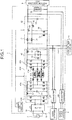
- FIG. 1 is a block diagram illustrating an example of the configuration of the vehicle power supply device 1 in the embodiment.
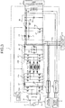
- FIG. 2 is a block diagram illustrating an example of charging by an alternating-current power supply 2 of the vehicle power supply device 1 in the embodiment.
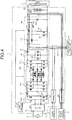
- FIG. 3 is a block diagram illustrating an example of charging by a quick charger 5 of the vehicle power supply device 1 in the embodiment.
- FIG. 4 is a block diagram illustrating an example of charging by a superquick charger 6 of the vehicle power supply device 1 in the embodiment.
- FIG. 5 is a block diagram illustrating an example of discharging of the vehicle power supply device 1 in the embodiment.
- the vehicle power supply device 1 is mounted on, for example, a vehicle such as an electric vehicle (EV) and a plug-in hybrid vehicle (PHV) and supplies electric power to a high-voltage load unit 3 including an inverter and a motor generator and a low-voltage load unit 4 including an electric air conditioner that has a lower voltage than that of the high-voltage load unit 3.
- a vehicle such as an electric vehicle (EV) and a plug-in hybrid vehicle (PHV) and supplies electric power to a high-voltage load unit 3 including an inverter and a motor generator and a low-voltage load unit 4 including an electric air conditioner that has a lower voltage than that of the high-voltage load unit 3.
- the vehicle power supply device 1 includes an AC inlet 10 as a power supply connector, a high-voltage battery 20 as a battery, a filter 30, an AC/DC converter 40, a bidirectional two-phase chopper circuit 50 as a bidirectional DC/DC converter, a connector 61 as a first direct-current power supply connector, a connector 62 as a second direct-current power supply connector, and a controller 70.
- the AC inlet 10 is a connector that is connected to an AC outlet of an AC power supply (alternating-current power supply unit) 2 for domestic use. A part of the AC inlet 10 is exposed to the outside of the vehicle. The AC inlet 10 is connected to the AC outlet for domestic use and alternating-current power is output thereto from the AC power supply 2.
- AC power supply alternating-current power supply unit
- the high-voltage battery 20 supplies high-voltage direct-current power.
- the high-voltage battery 20 has a voltage of, for example, approximately 800 V to 1000 V and supplies relatively high-voltage direct-current power.
- the high-voltage battery 20 is connected to the AC power supply 2 with the AC/DC converter 40 and the bidirectional two-phase chopper circuit 50 interposed therebetween and is charged with electric power supplied from the AC power supply 2.
- the high-voltage battery 20 is connected to the connector 61 and is charged with electric power supplied from the quick charger 5 through the connector 61.
- the high-voltage battery 20 is connected to the connector 62 and is charged with electric power supplied from the superquick charger 6 through the connector 62.
- the high-voltage battery 20 is connected to the low-voltage load unit 4 with the bidirectional two-phase chopper circuit 50 interposed therebetween and supplies electric power to the low-voltage load unit 4.
- the high-voltage battery 20 is connected to the high-voltage load unit 3 and supplies electric power to the high-voltage load unit 3.
- An inverter of the high-voltage load unit 3 converts the direct-current power supplied from the high-voltage battery 20 into alternating-current power and supplies the alternating-current power to a motor generator.
- the motor generator is driven with the alternating-current power supplied from the inverter to rotate a wheel of the vehicle.
- the filter 30 reduces noise.
- the filter 30 is connected to the AC inlet 10 and reduces noise of the alternating-current power output from the AC inlet 10.
- the filter 30 is connected to the AC/DC converter 40 and outputs the alternating-current power with the reduced noise to the AC/DC converter 40.
- the AC/DC converter 40 converts alternating-current power into direct-current power.
- the AC/DC converter 40 is an insulating-type power factor correction (PFC) circuit improving a power factor and includes a rectifying circuit 41A and a DC/DC converter 41B.
- the rectifying circuit 41A rectifies alternating-current power into direct-current power.
- the rectifying circuit 41A is, for example, a full-bridge circuit having four switching elements.
- the rectifying circuit 41A is connected to the filter 30 and rectifies the alternating-current power output from the filter 30 into direct-current power.
- the rectifying circuit 41A is connected to the DC/DC converter 41B and outputs the rectified direct-current power to the DC/DC converter 41B.
- the DC/DC converter 41B boosts a voltage.
- the DC/DC converter 41B is, for example, a one-converter circuit using a three-phase dual active bridge (DAB).
- the DC/DC converter 41B includes a first bridge circuit 41a, a second bridge circuit 41b, a transformer 41c, capacitors C1 and C2, coil portions 41d and 41e, and coils L1 and L2.
- the first bridge circuit 41a is a three-phase full-bridge circuit having six switching elements.
- the first bridge circuit 41a is connected to the rectifying circuit 41A and the transformer 41c.
- the first bridge circuit 41a converts the direct-current power output from the rectifying circuit 41A into alternating-current power and outputs the alternating-current power to the transformer 41c.
- the second bridge circuit 41b is a three-phase full-bridge circuit having six switching elements.
- the second bridge circuit 41b is connected to the transformer 41c and converts alternating-current power output from the transformer 41c into direct-current power.
- the second bridge circuit 41b is connected to the bidirectional two-phase chopper circuit 50 and the low-voltage load unit 4 and outputs the converted direct-current power to the bidirectional two-phase chopper circuit 50 and the low-voltage load unit 4.
- the transformer 41c includes a primary winding portion having three coils and a secondary winding portion having three coils and being magnetically coupled to the primary winding portion.
- the primary winding portion and the secondary winding portion are insulated from each other.
- the transformer 41c can thereby insulate the AC inlet 10 and a high-voltage power supply system including the quick charger 5, the high-voltage load unit 3 such as the motor generator, and the high-voltage battery 20.
- the vehicle power supply device 1 connects the high-voltage power supply system and the AC inlet 10 with the AC/DC converter 40 interposed therebetween, so that the high-voltage power supply system can be easily isolated, thereby improving maintainability.
- the primary winding portion of the transformer 41c is connected to the first bridge circuit 41a with the coil portion 41d interposed therebetween.
- the secondary winding portion of the transformer 41c is connected to the second bridge circuit 41b with the coil portion 41e interposed therebetween.
- the transformer 41c converts a voltage by electromagnetic induction of the primary winding portion and the secondary winding portion.
- the transformer 41c boosts a voltage of electric power supplied from the AC power supply 2.
- the capacitor C1 is provided between the first bridge circuit 41a and the rectifying circuit 41A and smooths the direct-current power that is output from the rectifying circuit 41A to the first bridge circuit 41a.
- the capacitor C2 is provided between the second bridge circuit 41b and the bidirectional two-phase chopper circuit 50 and smooths the direct-current power that is output from the second bridge circuit 41b to the bidirectional two-phase chopper circuit 50.
- the first bridge circuit 41a and the rectifying circuit 41A are connected to each other with the coil L1 interposed therebetween, and the second bridge circuit 41b and the bidirectional two-phase chopper circuit 50 are connected to each other with the coil L2 interposed therebetween.
- the bidirectional two-phase chopper circuit 50 boosts or steps down a voltage.
- the bidirectional two-phase chopper circuit 50 is connected to the AC/DC converter 40, the connector 61, the high-voltage battery 20, and the low-voltage load unit 4.
- the bidirectional two-phase chopper circuit 50 includes switching elements 51 to 54 allowing conduction of a current or blocking the current, coupling inductors (coils) L3 and L4 outputting induction currents in accordance with operations of the switching elements 51 to 54, and a smoothing capacitor C3.
- the bidirectional two-phase chopper circuit 50 turns ON/OFF the switching elements 51 to 54, boosts a voltage of the direct-current power output from the AC/DC converter 40, and outputs it to the high-voltage battery 20.
- the bidirectional two-phase chopper circuit 50 for example, doubles the voltage of the direct-current power output from the AC/DC converter 40.
- the bidirectional two-phase chopper circuit 50 turns ON/OFF the switching elements 51 to 54, steps down a voltage of direct-current power output from the high-voltage battery 20, and outputs it to the low-voltage load unit 4.
- the bidirectional two-phase chopper circuit 50 for example, steps down, by half, the voltage of the direct-current power output from the high-voltage battery 20.
- the capacitor C3 is connected to the bidirectional two-phase chopper circuit 50 and smooths the direct-current power output from the bidirectional two-phase chopper circuit 50.
- the smoothing capacitor C3 is connected to the high-voltage battery 20 and outputs the smoothed direct-current power to the high-voltage battery 20.
- the connector 61 is a connector connected to the quick charger 5 supplying direct-current power.
- the quick charger 5 supplies direct-current power of a voltage of, for example, approximately 400 V to 500 V.
- the connector 61 is connected to the bidirectional two-phase chopper circuit 50 and outputs the direct-current power supplied from the quick charger 5 to the bidirectional two-phase chopper circuit 50.
- the connector 61 is connected to the low-voltage load unit 4 and outputs the direct-current power supplied from the quick charger 5 to the low-voltage load unit 4.
- the connector 62 is a connector connected to the superquick charger 6 supplying direct-current power.
- the superquick charger 6 supplies direct-current power of a higher voltage than that of the quick charger 5 and supplies direct-current power of a voltage of, for example, approximately 800 V to 1000 V.
- the connector 62 is connected to the high-voltage battery 20 and outputs the direct-current power supplied from the superquick charger 6 directly to the high-voltage battery 20.
- the controller 70 controls the AC/DC converter 40 and the bidirectional two-phase chopper circuit 50.
- the controller 70 includes an electronic circuit configured by, as a main body, a well-known micro computer including a central processing unit (CPU), a read only memory (ROM) configuring a storage unit, a random access memory (RAM), and an interface.
- the controller 70 monitors connection states to the power supply units.
- the controller 70 monitors, for example, a connection state between the AC power supply 2 and the AC inlet 10, a connection state between the quick charger 5 and the connector 61, and a connection state between the superquick charger 6 and the connector 62.
- the controller 70 charges the high-voltage battery 20 with the direct-current power converted by the AC/DC converter 40 and boosted by the bidirectional two-phase chopper circuit 50. Furthermore, the controller 70 supplies, to the low-voltage load unit 4, the direct-current power converted by the AC/DC converter 40.
- the controller 70 charges the high-voltage battery 20 with the direct-current power boosted by the bidirectional two-phase chopper circuit 50. Furthermore, the controller 70 supplies the direct-current power to the low-voltage load unit 4 from the quick charger 5 without passing through the bidirectional two-phase chopper circuit 50.
- the controller 70 charges the high-voltage battery 20 with the direct-current power from the superquick charger 6 without passing through the bidirectional two-phase chopper circuit 50. Furthermore, the controller 70 supplies, to the low-voltage load unit 4, the direct-current power of the high-voltage battery 20 that has been stepped down by the bidirectional two-phase chopper circuit 50.
- the controller 70 supplies the direct-current power to the high-voltage load unit 3 from the high-voltage battery 20 without passing through the bidirectional two-phase chopper circuit 50 and supplies, to the low-voltage load unit 4, the direct-current power of the high-voltage battery 20 that has been stepped down by the bidirectional two-phase chopper circuit 50.
- FIG. 6 is a flowchart illustrating the example of the operations of the vehicle power supply device 1 in the embodiment.
- the vehicle power supply device 1 determines, by the controller 70, whether supply of electric power from the AC power supply 2 is started (step S1).
- the controller 70 supplies the electric power to the high-voltage battery 20 and the low-voltage load unit 4 from the AC power supply 2 (step S2).
- the controller 70 for example, charges the high-voltage battery 20 with direct-current power converted by the AC/DC converter 40 and boosted by the bidirectional two-phase chopper circuit 50.
- the controller 70 supplies, to the low-voltage load unit 4, direct-current power of an intermediate voltage Vm boosted by the AC/DC converter 40, and the processing ends.
- the intermediate voltage Vm is, for example, approximately 400 V to 500 V.
- step S3 the controller 70 determines whether supply of electric power from the quick charger 5 is started.
- step S4 the controller 70 supplies the electric power to the high-voltage battery 20 and the low-voltage load unit 4 from the quick charger 5 (step S4).
- the controller 70 for example, charges the high-voltage battery 20 with direct-current power boosted by the bidirectional two-phase chopper circuit 50.
- the controller 70 supplies direct-current power of the intermediate voltage Vm to the low-voltage load unit 4 from the quick charger 5 without passing through the bidirectional two-phase chopper circuit 50, and the processing ends.
- the controller 70 determines whether supply of electric power from the superquick charger 6 is started (step S5).
- the controller 70 supplies the electric power to the high-voltage battery 20 from the superquick charger 6 and supplies the electric power to the low-voltage load unit 4 from the high-voltage battery 20 (step S6).
- the controller 70 for example, charges the high-voltage battery 20 with direct-current power from the superquick charger 6 without passing through the bidirectional two-phase chopper circuit 50.
- the controller 70 supplies, to the low-voltage load unit 4, direct-current power of the intermediate voltage Vm of the high-voltage battery 20 that has been stepped down by the bidirectional two-phase chopper circuit 50, and the processing ends.
- the controller 70 supplies electric power to the low-voltage load unit 4 and the high-voltage load unit 3 from the high-voltage battery 20 (step S7).
- the controller 70 for example, supplies direct-current power to the high-voltage load unit 3 from the high-voltage battery 20 without passing through the bidirectional two-phase chopper circuit 50 and supplies, to the low-voltage load unit 4, direct-current power of the intermediate voltage Vm that has been stepped down by the bidirectional two-phase chopper circuit 50.
- the vehicle power supply device 1 in the embodiment includes the high-voltage battery 20, the AC inlet 10, the AC/DC converter 40, the bidirectional two-phase chopper circuit 50, the connector 61, the connector 62, and the controller 70.
- the high-voltage battery 20 supplies the direct-current power to the high-voltage load unit 3 and the low-voltage load unit 4 having a lower voltage than that of the high-voltage load unit 3.
- the AC inlet 10 is connected to the AC power supply 2 supplying the alternating-current power to the high-voltage battery 20.
- the AC/DC converter 40 converts, into the direct-current power, the alternating-current power being supplied to the high-voltage battery 20 from the AC power supply 2.
- the bidirectional two-phase chopper circuit 50 boosts the voltage of the direct-current power converted by the AC/DC converter 40 to output it to the high-voltage battery 20 and steps down the voltage of the direct-current power being supplied to the low-voltage load unit 4 from the high-voltage battery 20.
- the connector 61 is connected to the quick charger 5 supplying the direct-current power.
- the connector 62 is connected to the superquick charger 6 supplying the direct-current power having a higher voltage than that of the quick charger 5.
- the controller 70 controls the AC/DC converter 40 and the bidirectional two-phase chopper circuit 50.
- the controller 70 charges the high-voltage battery 20 with the direct-current power converted by the AC/DC converter 40 and boosted by the bidirectional two-phase chopper circuit 50 and supplies the direct-current power converted by the AC/DC converter 40 to the low-voltage load unit 4.
- the controller 70 charges the high-voltage battery 20 with the direct-current power boosted by the bidirectional two-phase chopper circuit 50 and supplies the direct-current power to the low-voltage load unit 4 from the quick charger 5 without passing through the bidirectional two-phase chopper circuit 50.
- the controller 70 charges the high-voltage battery 20 with the direct-current power from the superquick charger 6 without passing through the bidirectional two-phase chopper circuit 50 and supplies, to the low-voltage load unit 4, the direct-current power of the high-voltage battery 20 that has been stepped down by the bidirectional two-phase chopper circuit 50.
- the controller 70 is capable of supplying the direct-current power to the high-voltage load unit 3 from the high-voltage battery 20 without passing through the bidirectional two-phase chopper circuit 50 and supplies, to the low-voltage load unit 4, the direct-current power of the high-voltage battery 20 that has been stepped down by the bidirectional two-phase chopper circuit 50.
- the vehicle power supply device 1 can charge the high-voltage battery 20 with the direct-current power from the AC power supply 2 by the AC/DC converter 40 and the bidirectional two-phase chopper circuit 50.
- the vehicle power supply device 1 can step down the direct-current power of the high-voltage battery 20 and supply it to the low-voltage load unit 4 by the bidirectional two-phase chopper circuit 50.
- the vehicle power supply device 1 can thereby use the bidirectional two-phase chopper circuit 50 as a boosting converter when charging the high-voltage battery 20 and a step-down converter when discharging the high-voltage battery 20.
- the vehicle power supply device 1 can use the bidirectional two-phase chopper circuit 50 as the boosting converter in charging and the step-down converter in discharging.
- the vehicle power supply device 1 can thereby substantially prevent increase in the number of power converters, thereby substantially preventing the device from being increased in size.
- the vehicle power supply device 1 can reduce manufacturing cost.
- the vehicle power supply device 1 can generate the intermediate voltage Vm when the high-voltage battery 20 is charged with electric power from any of the AC power supply 2, the quick charger 5, and the superquick charger 6 and supply the direct-current power of the intermediate voltage Vm to the low-voltage load unit 4.
- the vehicle power supply device 1 generates the intermediate voltage Vm also during charging of the high-voltage battery 20, thereby operating the low-voltage load unit 4 such as the electric air conditioner also during charging of the high-voltage battery 20.
- the vehicle power supply device 1 can decrease a creepage distance relatively by generating the intermediate voltage Vm, thereby substantially preventing the device from being increased in size. Since the vehicle power supply device 1 generates the intermediate voltage Vm, the low-voltage load unit 4, for example, does not need special specifications for high voltage, and manufacturing cost of the low-voltage load unit 4 can be reduced.
- the AC/DC converter 40 includes the rectifying circuit 41A rectifying the alternating-current power supplied from the AC power supply 2 into the direct-current power and the insulating-type DC/DC converter 41B boosting the voltage of the direct-current power rectified by the rectifying circuit 41A.
- the conventional vehicle power supply device for example, uses a non-insulating-type PFC circuit and an insulating-type DC/DC converter.
- the vehicle power supply device 1 in the embodiment connects an output portion of the AC/DC converter 40 (PFC circuit) to the high-voltage power supply system such as the quick charger 5. Insulating performance between the AC inlet 10 and the high-voltage power supply system can therefore be ensured by insulating the AC/DC converter 40.
- the bidirectional two-phase chopper circuit 50 includes the chopper circuit having the switching elements 51 to 54 allowing conduction of a current or blocking the current and the coupling inductors L3 and L4 outputting the induction currents in accordance with the operations of the switching elements 51 to 54.
- the vehicle power supply device 1 can operate the bidirectional two-phase chopper circuit 50 with magnification maximizing effects of the coupling inductors L3 and L4 by adjusting the intermediate voltage Vm by the AC/DC converter 40.
- the vehicle power supply device 1 can thereby reduce cores of the coupling inductors L3 and L4 and the smoothing capacitor C3 in size, thereby substantially preventing the device from being increased in size.
- FIG. 7 is a block diagram illustrating an example of the configuration of a vehicle power supply device 1A according to the modification of the embodiment.
- the vehicle power supply device 1A in the modification differs from the vehicle power supply device 1 in the embodiment in the point that it uses an insulating-type bidirectional DC/DC converter 50A instead of the bidirectional two-phase chopper circuit 50 of the vehicle power supply device 1.
- the bidirectional DC/DC converter 50A includes a first bridge circuit 55a, a second bridge circuit 55b, and a transformer 55c.
- the bidirectional DC/DC converter 50A can insulate a high-voltage power supply system including the high-voltage load unit 3 and the high-voltage battery 20 and the intermediate voltage Vm.
- the controller 70 when electric power is supplied from the high-voltage battery 20, the controller 70 supplies the electric power to the high-voltage load unit 3 and the low-voltage load unit 4, as an example, the controller 70 is not limited thereto.
- the controller 70 may supply the electric power to the low-voltage load unit 4 only without supplying it to the high-voltage load unit 3.
- the AC/DC converter 40 includes the rectifying circuit 41A and the insulating-type DC/DC converter 41B as an example, the AC/DC converter 40 is not limited thereto and may have another circuit configuration.
- the DC/DC converter 41B is the one-converter circuit using the three-phase DAB as an example, the DC/DC converter 41B is not limited thereto and may be a one-converter circuit using a two-phase DAB or have another circuit configuration.
- the bidirectional two-phase chopper circuit 50 includes the chopper circuit having the switching elements 51 to 54 and the coupling inductors L3 and L4 as an example, the bidirectional two-phase chopper circuit 50 is not limited thereto and may have another circuit configuration.
- the high-voltage load unit 3 includes the inverter and the motor generator, as an example, it is not limited thereto and may include other electronic devices.
- the low-voltage load unit 4 includes the electric air conditioner, as an example, it is not limited thereto and may include other electronic devices.
- controller 53 is provided in the power conversion unit 50, as an example, it is not limited to be provided in this manner and may be provided at another place.
- the vehicle power supply device can use the bidirectional DC/DC converter both as the boosting converter in charging and as the step-down converter in discharging.
- the device can therefore be substantially prevented from being increased in size.
Landscapes
- Engineering & Computer Science (AREA)
- Power Engineering (AREA)
- Mechanical Engineering (AREA)
- Transportation (AREA)
- Charge And Discharge Circuits For Batteries Or The Like (AREA)
- Electric Propulsion And Braking For Vehicles (AREA)
- Dc-Dc Converters (AREA)
- Rectifiers (AREA)
Claims (3)
- Fahrzeug-Stromversorgungsvorrichtung (1, 1A), umfassend:eine Batterie (20), die eingerichtet ist, Gleichstromleistung an eine Hochspannungs-Lasteinheit (3) zu liefern;einen Wechselstrom-Leistungsversorgungsverbinder (10), der eingerichtet ist, mit einer Wechselstrom-Leistungsversorgungseinheit (2) verbunden zu werden, die Wechselstromleistung an die Batterie (20) liefert;einen AC/DC-Wandler (40), der eingerichtet ist, die Wechselstromleistung, die von der Wechselstrom-Leistungsversorgungseinheit (2) geliefert wird, in Gleichstromleistung zu wandeln;einen ersten Gleichstrom-Leistungsversorgungsverbinder (61), der eingerichtet ist, mit einer ersten Gleichstrom-Leistungsversorgungseinheit (5) verbunden zu werden, die Gleichstromleistung liefert;dadurch gekennzeichnet, dassdie Batterie (20) ferner eingerichtet ist, Gleichstromleistung an eine Niedrigspannungs-Lasteinheit (4) zu liefern, die eine niedrigere Spannung als eine Spannung der Hochspannungs-Lasteinheit (3) aufweist; und durcheinen bidirektionalen DC/DC-Wandler (50, 50A), der eingerichtet ist, eine von dem AC/DC-Wandler (40) gewandelte Spannung der Gleichstromleistung zu erhöhen, um die Gleichstromleistung an die Batterie (20) auszugeben, und eine Spannung der Gleichstromleistung, die an die Niedrigspannungs-Lasteinheit (4) von der Batterie (20) geliefert wird, zu verringern;einen zweiten Gleichstrom-Leistungsversorgungsverbinder (62), der eingerichtet ist, mit einer zweiten Gleichstrom-Leistungsversorgungseinheit (6) verbunden zu werden, die Gleichstromleistung liefert, die eine höhere Spannung als eine Spannung der ersten Gleichstrom-Leistungsversorgungseinheit (5) aufweist; undeine Steuerung (70), die eingerichtet ist, den AC/DC-Wandler (40) und den bidirektionalen DC/DC-Wandler (50, 50A) zu steuern, wobeiwenn die Wechselstromleistung von der Wechselstrom-Leistungsversorgungseinheit (2) geliefert wird, die Steuerung (70) eingerichtet ist, die Batterie (20) mit Gleichstromleistung zu laden, die von dem AC/DC-Wandler (40) gewandelt und von dem bidirektionalen DC/DC-Wandler (50, 50A) erhöht wurde, und die Gleichstromleistung, die von dem AC/DC-Wandler (40) gewandelt wurde, an die Niedrigspannungs-Lasteinheit (4) zu liefern,wenn die Gleichstromleistung von der ersten Gleichstrom-Leistungsversorgungseinheit (5) geliefert wird und keine elektrische Leistung von der Wechselstrom-Leistungsversorgungseinheit (2) geliefert wird, die Steuerung (70) eingerichtet ist, die Batterie (20) mit Gleichstromleistung zu laden, die von dem bidirektionalen DC/DC-Wandler (50, 50A) erhöht wurde, und die Gleichstromleistung von der ersten Gleichstrom-Leistungsversorgungseinheit (5) an die Niedrigspannungs-Lasteinheit (4) zu liefern, ohne den bidirektionalen DC/DC-Wandler (50, 50A) zu durchlaufen,wenn die Gleichstromleistung von der zweiten Gleichstrom-Leistungsversorgungseinheit (6) geliefert wird, keine elektrische Leistung von der Wechselstrom-Leistungsversorgungseinheit (2) geliefert wird, und keine elektrische Leistung von der ersten Gleichstrom-Leistungsversorgungseinheit (5) geliefert wird, die Steuerung (70) eingerichtet ist, die Batterie (20) mit der Gleichstromleistung von der zweiten Gleichstrom-Leistungsversorgungseinheit (6) zu laden, ohne den bidirektionalen DC/DC-Wandler (50, 50A) zu durchlaufen, und Gleichstromleistung der Batterie (20), die von dem bidirektionalen DC/DC-Wandler (50, 50A) verringert wurde, an die Niedrigspannungs-Lasteinheit (4) zu liefern, undwenn keine elektrische Leistung von jeder der Wechselstrom-Leistungsversorgungseinheit (2), der ersten Gleichstrom-Leistungsversorgungseinheit (5) und der zweiten Gleichstrom-Leistungsversorgungseinheit (6) geliefert wird, die Steuerung (70) eingerichtet ist, die Gleichstromleistung an die Hochspannungs-Lasteinheit (3) von der Batterie (20), ohne den bidirektionalen DC/DC-Wandler (50, 50A) zu durchlaufen, zu liefern, und die Gleichstromleistung der Batterie (20), die von dem bidirektionalen DC/DC-Wandler (50, 50A) verringert wurde, an die Niedrigspannungs-Lasteinheit (4) zu liefern.
- Fahrzeug-Stromversorgungsvorrichtung (1, 1A) nach Anspruch 1, wobei der AC/DC-Wandler (40) eine Gleichrichterschaltung (41A), die eingerichtet ist, die Wechselstromleistung, die von der Wechselstrom-Leistungsversorgungseinheit (2) geliefert wird, in Gleichstromleistung gleichzurichten, und einen Isolationstyp-DC/DC-Wandler (41B), der eingerichtet ist, eine Spannung der Gleichstromleistung, die von der Gleichrichterschaltung (41) gleichgerichtet wird, zu erhöhen, enthält.
- Fahrzeug-Stromversorgungsvorrichtung (1) nach Anspruch 1 oder 2, wobei
der bidirektionale DC/DC-Wandler (50) eine Zerhacker-Schaltung, die ein Schaltelement (51-54) aufweist, das eingerichtet ist, ein Leiten eines Stroms zu ermöglichen oder den Strom zu blockieren, und eine Spule (L3, L4), die eingerichtet ist, einen Induktionsstrom entsprechend einem Betrieb des Schaltelements (51-54) auszugeben, enthält.
Applications Claiming Priority (1)
| Application Number | Priority Date | Filing Date | Title |
|---|---|---|---|
| JP2018171465A JP6811219B2 (ja) | 2018-09-13 | 2018-09-13 | 車両電源装置 |
Publications (2)
| Publication Number | Publication Date |
|---|---|
| EP3623200A1 EP3623200A1 (de) | 2020-03-18 |
| EP3623200B1 true EP3623200B1 (de) | 2021-04-28 |
Family
ID=67658746
Family Applications (1)
| Application Number | Title | Priority Date | Filing Date |
|---|---|---|---|
| EP19191619.6A Active EP3623200B1 (de) | 2018-09-13 | 2019-08-14 | Stromversorgungsvorrichtung für ein fahrzeug |
Country Status (4)
| Country | Link |
|---|---|
| US (1) | US11296533B2 (de) |
| EP (1) | EP3623200B1 (de) |
| JP (1) | JP6811219B2 (de) |
| CN (1) | CN110896277B (de) |
Cited By (1)
| Publication number | Priority date | Publication date | Assignee | Title |
|---|---|---|---|---|
| EP4527681A4 (de) * | 2022-06-29 | 2025-09-10 | Huawei Digital Power Tech Co Ltd | Bordlader, bordstromsystem und elektrofahrzeug |
Families Citing this family (18)
| Publication number | Priority date | Publication date | Assignee | Title |
|---|---|---|---|---|
| US10340724B2 (en) * | 2017-04-04 | 2019-07-02 | Gm Gloval Technology Operations Llc | Inductive and conductive onboard charging systems |
| EP3719982B8 (de) * | 2019-04-02 | 2022-12-21 | ABB E-mobility B.V. | Dreiphasiger wechselstrom-gleichstrom-leistungswandler |
| US12640656B2 (en) | 2020-03-24 | 2026-05-26 | Tvs Motor Company Limited | Bi-directional DC-DC converter |
| US12024037B2 (en) * | 2021-11-03 | 2024-07-02 | Zero Motorcycles, Inc. | Charging system, vehicle including a charging system, and charging method |
| JP7410917B2 (ja) * | 2021-11-05 | 2024-01-10 | 矢崎総業株式会社 | 車載充電器 |
| CN116118530A (zh) * | 2021-11-12 | 2023-05-16 | 通用汽车环球科技运作有限责任公司 | 用于电池电动车的多功能dc-dc转换器 |
| DE102022110039A1 (de) * | 2022-04-26 | 2023-10-26 | Dr. Ing. H.C. F. Porsche Aktiengesellschaft | Verfahren und Vorrichtung für geglättete Versorgungsspannung von Hochvolt-Verbrauchern am Hochvolt-Zwischenkreis des Ladegerätes |
| CN115360777A (zh) * | 2022-06-09 | 2022-11-18 | 江西微电新能源有限公司 | 户外储能电源 |
| FR3139053A1 (fr) * | 2022-08-29 | 2024-03-01 | Psa Automobiles Sa | Ensemble de recharge d’une batterie electrique de traction |
| FR3140813A1 (fr) * | 2022-10-12 | 2024-04-19 | Psa Automobiles Sa | Vehicule automobile comprenant un systeme de chargeur embarque pour des recharges a differentes tensions de bornes, systeme et procede sur la base d’un tel vehicule |
| JP7794100B2 (ja) * | 2022-10-24 | 2026-01-06 | トヨタ自動車株式会社 | 車両 |
| US12654579B2 (en) * | 2022-10-28 | 2026-06-16 | Evjam Llc | Electric vehicle charging system with charging bus charging robot |
| DE102022212673A1 (de) * | 2022-11-28 | 2024-05-29 | Robert Bosch Gesellschaft mit beschränkter Haftung | Ladegerät zum Aufladen einer Batterie eines Fahrzeugs und Verfahren zum Betrieb des Ladegerätes |
| US12068632B2 (en) | 2023-01-17 | 2024-08-20 | Delta Electronics, Inc. | Charging system |
| CN115912582B (zh) * | 2023-03-08 | 2023-07-14 | 紫光同芯微电子有限公司 | 一种无线充电器及其控制方法 |
| DE102023116904A1 (de) * | 2023-06-27 | 2025-01-02 | Seg Automotive Germany Gmbh | Elektrische Maschineneinheit, Fahrzeug und Verfahren zum Betreiben einer elektrischen Maschineneinheit |
| DE102024201378A1 (de) | 2024-02-15 | 2025-08-21 | Siemens Aktiengesellschaft | Stationäre Gleichspannungs-Ladeeinrichtung für elektrisch angetriebene Fahrzeuge, Verfahren zum Bereitstellen einer Gleichspannungs-Ladeeinrichtung für elektrisch angetriebene Fahrzeuge |
| US12533977B1 (en) * | 2024-11-01 | 2026-01-27 | GM Global Technology Operations LLC | Power splitter based on multifunctional OBCM |
Family Cites Families (25)
| Publication number | Priority date | Publication date | Assignee | Title |
|---|---|---|---|---|
| US8080973B2 (en) * | 2008-10-22 | 2011-12-20 | General Electric Company | Apparatus for energy transfer using converter and method of manufacturing same |
| JP2010119257A (ja) * | 2008-11-14 | 2010-05-27 | Toyota Motor Corp | 電源装置および車両 |
| US9000614B2 (en) * | 2009-08-11 | 2015-04-07 | General Electric Company | System for multiple energy storage and management and method of making same |
| US9013066B2 (en) * | 2010-10-28 | 2015-04-21 | Honeywell International Inc. | High voltage electric accumulators with internal distributed DC-DC converters for self regulation and protection |
| JP2013017357A (ja) * | 2011-07-06 | 2013-01-24 | Toyota Motor Corp | プラグイン車両 |
| WO2013035178A1 (ja) * | 2011-09-08 | 2013-03-14 | トヨタ自動車株式会社 | 車両の充電システム、車両の充電方法、電力供給システムおよび電力供給方法 |
| DE102011083020A1 (de) * | 2011-09-20 | 2013-03-21 | Robert Bosch Gmbh | Ladevorrichtung, insbesondere für Kraftfahrzeuge, Verfahren und Kraftfahrzeug |
| KR101585117B1 (ko) * | 2011-12-08 | 2016-01-21 | 가부시키가이샤 에네르기 오요 기쥬츠켄큐쇼 | 급속충전용 전원 시스템 |
| EP2858202B1 (de) * | 2012-05-25 | 2020-07-15 | Panasonic Intellectual Property Management Co., Ltd. | Fahrzeuginterne stromversorgungsvorrichtung |
| JP5575185B2 (ja) * | 2012-06-15 | 2014-08-20 | オムロンオートモーティブエレクトロニクス株式会社 | 車両用電源制御装置 |
| US9434263B2 (en) * | 2012-09-05 | 2016-09-06 | Lear Corporation | Multi-mode battery charger |
| KR20140054796A (ko) * | 2012-10-29 | 2014-05-09 | 삼성전기주식회사 | 전원 공급 장치 및 전기 자동차의 전원 공급 장치 |
| FR2997583B1 (fr) * | 2012-10-31 | 2014-11-21 | Valeo Equip Electr Moteur | Systeme d'alimentation electrique a double stockeurs d'energie electrique d'un vehicule automobile ou hybride |
| US9787112B2 (en) * | 2013-04-02 | 2017-10-10 | Tesla, Inc. | Inter-protocol charging adapter |
| DE102013225493A1 (de) * | 2013-08-12 | 2015-02-12 | Hyundai Motor Company | Umwandlervorrichtung und -verfahren eines Elektrofahrzeugs |
| JP6511224B2 (ja) * | 2014-04-23 | 2019-05-15 | 日立オートモティブシステムズ株式会社 | 電源装置 |
| JP2016199153A (ja) * | 2015-04-10 | 2016-12-01 | トヨタ自動車株式会社 | 車載二次電池の冷却システム |
| US10377247B2 (en) * | 2015-07-27 | 2019-08-13 | Ford Global Technologies, Llc | High voltage battery contactor arrangement for DC fast charging |
| JP6614646B2 (ja) | 2015-08-21 | 2019-12-04 | 矢崎総業株式会社 | 車両用電源システム |
| US10044209B2 (en) * | 2015-12-01 | 2018-08-07 | GM Global Technology Operations LLC | Method and apparatus for charging a high-voltage battery assembly |
| US20180069425A1 (en) * | 2016-09-07 | 2018-03-08 | Thunder Power New Energy Vehicle Development Company Limited | Electric vehicle system |
| EP3299211B1 (de) * | 2016-09-26 | 2019-11-06 | Volvo Car Corporation | Fahrzeuglade-schnittstelleneinheit, ein system zu laden eines fahrzeugs und ein fahrzeug |
| DE102016122008A1 (de) * | 2016-11-16 | 2018-05-17 | Dr. Ing. H.C. F. Porsche Aktiengesellschaft | Allstrom-Ladegerät |
| CN107627881B (zh) * | 2017-09-18 | 2020-11-17 | 电子科技大学 | 一种电动汽车的充放电及电机驱动一体化装置 |
| JP7103018B2 (ja) * | 2018-07-25 | 2022-07-20 | 日産自動車株式会社 | 電動車両の電源システム |
-
2018
- 2018-09-13 JP JP2018171465A patent/JP6811219B2/ja active Active
-
2019
- 2019-08-09 US US16/537,473 patent/US11296533B2/en active Active
- 2019-08-14 EP EP19191619.6A patent/EP3623200B1/de active Active
- 2019-08-15 CN CN201910753367.3A patent/CN110896277B/zh active Active
Non-Patent Citations (1)
| Title |
|---|
| None * |
Cited By (1)
| Publication number | Priority date | Publication date | Assignee | Title |
|---|---|---|---|---|
| EP4527681A4 (de) * | 2022-06-29 | 2025-09-10 | Huawei Digital Power Tech Co Ltd | Bordlader, bordstromsystem und elektrofahrzeug |
Also Published As
| Publication number | Publication date |
|---|---|
| CN110896277B (zh) | 2022-11-18 |
| JP6811219B2 (ja) | 2021-01-13 |
| US11296533B2 (en) | 2022-04-05 |
| CN110896277A (zh) | 2020-03-20 |
| EP3623200A1 (de) | 2020-03-18 |
| US20200091753A1 (en) | 2020-03-19 |
| JP2020043728A (ja) | 2020-03-19 |
Similar Documents
| Publication | Publication Date | Title |
|---|---|---|
| US11296533B2 (en) | Vehicle power supply device | |
| EP3623207B1 (de) | Stromversorgungsvorrichtung für fahrzeug | |
| CN102271958B (zh) | 用于利用逆变器来控制供电装置的方法 | |
| CN108068650B (zh) | 通用电流充电器 | |
| US10763690B2 (en) | Vehicle-side charging circuit for a vehicle with electric drive, and method for operating a vehicle-side current converter, and use of at least one winding of a vehicle-side electric machine for intermediate storagectrical machine for buffer | |
| EP2653336B1 (de) | Stromversorgungsvorrichtung für ein elektrofahrzeug und steuerverfahren dafür | |
| KR102692322B1 (ko) | 통합형 컨버터 장치 | |
| KR101509709B1 (ko) | 전기 자동차의 충전 시스템 | |
| EP3623199A1 (de) | Stromversorgungsvorrichtung für fahrzeug | |
| KR102730545B1 (ko) | 차량용 전력 변환 시스템 및 그 제어 방법 | |
| CN104377791A (zh) | 一种电动车辆的转换装置和方法 | |
| US12549107B2 (en) | Charging device for a motor vehicle | |
| CN110521101A (zh) | 用于控制电动或混合动力车辆上车载的充电设备的方法 | |
| CN110326183A (zh) | 充电装置以及车载电源装置 | |
| JP2020108236A (ja) | 電力変換装置 | |
| WO2023079894A1 (ja) | 車載充電器 | |
| CN117615933A (zh) | 用于插电式电动运载工具中的充电器和dc-dc转换器 | |
| CN103650288A (zh) | 具有电池充电设备和车载电源供电级的系统 | |
| CN114649949A (zh) | 大容量双向隔离式直流-直流转换器及其控制方法 | |
| CN111969684B (zh) | 电动车充电电路及电动车 | |
| US20240006908A1 (en) | Apparatus and/or system for providing pulsating buffer converter with a boost circuit | |
| CN114944759A (zh) | Dc-dc转换器和车辆 | |
| US12401217B2 (en) | Vehicle power conversion system and method | |
| JP3859105B2 (ja) | ハイブリッド車用充電装置 | |
| WO2018029435A1 (en) | Dc power supply |
Legal Events
| Date | Code | Title | Description |
|---|---|---|---|
| PUAI | Public reference made under article 153(3) epc to a published international application that has entered the european phase |
Free format text: ORIGINAL CODE: 0009012 |
|
| STAA | Information on the status of an ep patent application or granted ep patent |
Free format text: STATUS: REQUEST FOR EXAMINATION WAS MADE |
|
| 17P | Request for examination filed |
Effective date: 20190814 |
|
| AK | Designated contracting states |
Kind code of ref document: A1 Designated state(s): AL AT BE BG CH CY CZ DE DK EE ES FI FR GB GR HR HU IE IS IT LI LT LU LV MC MK MT NL NO PL PT RO RS SE SI SK SM TR |
|
| AX | Request for extension of the european patent |
Extension state: BA ME |
|
| RBV | Designated contracting states (corrected) |
Designated state(s): AL AT BE BG CH CY CZ DE DK EE ES FI FR GB GR HR HU IE IS IT LI LT LU LV MC MK MT NL NO PL PT RO RS SE SI SK SM TR |
|
| GRAP | Despatch of communication of intention to grant a patent |
Free format text: ORIGINAL CODE: EPIDOSNIGR1 |
|
| STAA | Information on the status of an ep patent application or granted ep patent |
Free format text: STATUS: GRANT OF PATENT IS INTENDED |
|
| INTG | Intention to grant announced |
Effective date: 20201214 |
|
| GRAJ | Information related to disapproval of communication of intention to grant by the applicant or resumption of examination proceedings by the epo deleted |
Free format text: ORIGINAL CODE: EPIDOSDIGR1 |
|
| STAA | Information on the status of an ep patent application or granted ep patent |
Free format text: STATUS: REQUEST FOR EXAMINATION WAS MADE |
|
| INTC | Intention to grant announced (deleted) | ||
| GRAP | Despatch of communication of intention to grant a patent |
Free format text: ORIGINAL CODE: EPIDOSNIGR1 |
|
| STAA | Information on the status of an ep patent application or granted ep patent |
Free format text: STATUS: GRANT OF PATENT IS INTENDED |
|
| GRAS | Grant fee paid |
Free format text: ORIGINAL CODE: EPIDOSNIGR3 |
|
| GRAA | (expected) grant |
Free format text: ORIGINAL CODE: 0009210 |
|
| STAA | Information on the status of an ep patent application or granted ep patent |
Free format text: STATUS: THE PATENT HAS BEEN GRANTED |
|
| INTG | Intention to grant announced |
Effective date: 20210305 |
|
| AK | Designated contracting states |
Kind code of ref document: B1 Designated state(s): AL AT BE BG CH CY CZ DE DK EE ES FI FR GB GR HR HU IE IS IT LI LT LU LV MC MK MT NL NO PL PT RO RS SE SI SK SM TR |
|
| REG | Reference to a national code |
Ref country code: GB Ref legal event code: FG4D |
|
| REG | Reference to a national code |
Ref country code: CH Ref legal event code: EP |
|
| REG | Reference to a national code |
Ref country code: AT Ref legal event code: REF Ref document number: 1386696 Country of ref document: AT Kind code of ref document: T Effective date: 20210515 |
|
| REG | Reference to a national code |
Ref country code: DE Ref legal event code: R096 Ref document number: 602019004227 Country of ref document: DE |
|
| REG | Reference to a national code |
Ref country code: IE Ref legal event code: FG4D |
|
| REG | Reference to a national code |
Ref country code: LT Ref legal event code: MG9D |
|
| REG | Reference to a national code |
Ref country code: AT Ref legal event code: MK05 Ref document number: 1386696 Country of ref document: AT Kind code of ref document: T Effective date: 20210428 |
|
| PG25 | Lapsed in a contracting state [announced via postgrant information from national office to epo] |
Ref country code: LT Free format text: LAPSE BECAUSE OF FAILURE TO SUBMIT A TRANSLATION OF THE DESCRIPTION OR TO PAY THE FEE WITHIN THE PRESCRIBED TIME-LIMIT Effective date: 20210428 Ref country code: HR Free format text: LAPSE BECAUSE OF FAILURE TO SUBMIT A TRANSLATION OF THE DESCRIPTION OR TO PAY THE FEE WITHIN THE PRESCRIBED TIME-LIMIT Effective date: 20210428 Ref country code: FI Free format text: LAPSE BECAUSE OF FAILURE TO SUBMIT A TRANSLATION OF THE DESCRIPTION OR TO PAY THE FEE WITHIN THE PRESCRIBED TIME-LIMIT Effective date: 20210428 Ref country code: NL Free format text: LAPSE BECAUSE OF FAILURE TO SUBMIT A TRANSLATION OF THE DESCRIPTION OR TO PAY THE FEE WITHIN THE PRESCRIBED TIME-LIMIT Effective date: 20210428 Ref country code: AT Free format text: LAPSE BECAUSE OF FAILURE TO SUBMIT A TRANSLATION OF THE DESCRIPTION OR TO PAY THE FEE WITHIN THE PRESCRIBED TIME-LIMIT Effective date: 20210428 Ref country code: BG Free format text: LAPSE BECAUSE OF FAILURE TO SUBMIT A TRANSLATION OF THE DESCRIPTION OR TO PAY THE FEE WITHIN THE PRESCRIBED TIME-LIMIT Effective date: 20210728 |
|
| PG25 | Lapsed in a contracting state [announced via postgrant information from national office to epo] |
Ref country code: IS Free format text: LAPSE BECAUSE OF FAILURE TO SUBMIT A TRANSLATION OF THE DESCRIPTION OR TO PAY THE FEE WITHIN THE PRESCRIBED TIME-LIMIT Effective date: 20210828 Ref country code: GR Free format text: LAPSE BECAUSE OF FAILURE TO SUBMIT A TRANSLATION OF THE DESCRIPTION OR TO PAY THE FEE WITHIN THE PRESCRIBED TIME-LIMIT Effective date: 20210729 Ref country code: PL Free format text: LAPSE BECAUSE OF FAILURE TO SUBMIT A TRANSLATION OF THE DESCRIPTION OR TO PAY THE FEE WITHIN THE PRESCRIBED TIME-LIMIT Effective date: 20210428 Ref country code: LV Free format text: LAPSE BECAUSE OF FAILURE TO SUBMIT A TRANSLATION OF THE DESCRIPTION OR TO PAY THE FEE WITHIN THE PRESCRIBED TIME-LIMIT Effective date: 20210428 Ref country code: NO Free format text: LAPSE BECAUSE OF FAILURE TO SUBMIT A TRANSLATION OF THE DESCRIPTION OR TO PAY THE FEE WITHIN THE PRESCRIBED TIME-LIMIT Effective date: 20210728 Ref country code: RS Free format text: LAPSE BECAUSE OF FAILURE TO SUBMIT A TRANSLATION OF THE DESCRIPTION OR TO PAY THE FEE WITHIN THE PRESCRIBED TIME-LIMIT Effective date: 20210428 Ref country code: SE Free format text: LAPSE BECAUSE OF FAILURE TO SUBMIT A TRANSLATION OF THE DESCRIPTION OR TO PAY THE FEE WITHIN THE PRESCRIBED TIME-LIMIT Effective date: 20210428 Ref country code: PT Free format text: LAPSE BECAUSE OF FAILURE TO SUBMIT A TRANSLATION OF THE DESCRIPTION OR TO PAY THE FEE WITHIN THE PRESCRIBED TIME-LIMIT Effective date: 20210830 |
|
| REG | Reference to a national code |
Ref country code: NL Ref legal event code: MP Effective date: 20210428 |
|
| PG25 | Lapsed in a contracting state [announced via postgrant information from national office to epo] |
Ref country code: SK Free format text: LAPSE BECAUSE OF FAILURE TO SUBMIT A TRANSLATION OF THE DESCRIPTION OR TO PAY THE FEE WITHIN THE PRESCRIBED TIME-LIMIT Effective date: 20210428 Ref country code: ES Free format text: LAPSE BECAUSE OF FAILURE TO SUBMIT A TRANSLATION OF THE DESCRIPTION OR TO PAY THE FEE WITHIN THE PRESCRIBED TIME-LIMIT Effective date: 20210428 Ref country code: EE Free format text: LAPSE BECAUSE OF FAILURE TO SUBMIT A TRANSLATION OF THE DESCRIPTION OR TO PAY THE FEE WITHIN THE PRESCRIBED TIME-LIMIT Effective date: 20210428 Ref country code: CZ Free format text: LAPSE BECAUSE OF FAILURE TO SUBMIT A TRANSLATION OF THE DESCRIPTION OR TO PAY THE FEE WITHIN THE PRESCRIBED TIME-LIMIT Effective date: 20210428 Ref country code: DK Free format text: LAPSE BECAUSE OF FAILURE TO SUBMIT A TRANSLATION OF THE DESCRIPTION OR TO PAY THE FEE WITHIN THE PRESCRIBED TIME-LIMIT Effective date: 20210428 Ref country code: RO Free format text: LAPSE BECAUSE OF FAILURE TO SUBMIT A TRANSLATION OF THE DESCRIPTION OR TO PAY THE FEE WITHIN THE PRESCRIBED TIME-LIMIT Effective date: 20210428 Ref country code: SM Free format text: LAPSE BECAUSE OF FAILURE TO SUBMIT A TRANSLATION OF THE DESCRIPTION OR TO PAY THE FEE WITHIN THE PRESCRIBED TIME-LIMIT Effective date: 20210428 |
|
| REG | Reference to a national code |
Ref country code: DE Ref legal event code: R097 Ref document number: 602019004227 Country of ref document: DE |
|
| PLBE | No opposition filed within time limit |
Free format text: ORIGINAL CODE: 0009261 |
|
| STAA | Information on the status of an ep patent application or granted ep patent |
Free format text: STATUS: NO OPPOSITION FILED WITHIN TIME LIMIT |
|
| PG25 | Lapsed in a contracting state [announced via postgrant information from national office to epo] |
Ref country code: MC Free format text: LAPSE BECAUSE OF FAILURE TO SUBMIT A TRANSLATION OF THE DESCRIPTION OR TO PAY THE FEE WITHIN THE PRESCRIBED TIME-LIMIT Effective date: 20210428 |
|
| 26N | No opposition filed |
Effective date: 20220131 |
|
| REG | Reference to a national code |
Ref country code: BE Ref legal event code: MM Effective date: 20210831 |
|
| PG25 | Lapsed in a contracting state [announced via postgrant information from national office to epo] |
Ref country code: IS Free format text: LAPSE BECAUSE OF FAILURE TO SUBMIT A TRANSLATION OF THE DESCRIPTION OR TO PAY THE FEE WITHIN THE PRESCRIBED TIME-LIMIT Effective date: 20210828 Ref country code: LU Free format text: LAPSE BECAUSE OF NON-PAYMENT OF DUE FEES Effective date: 20210814 Ref country code: AL Free format text: LAPSE BECAUSE OF FAILURE TO SUBMIT A TRANSLATION OF THE DESCRIPTION OR TO PAY THE FEE WITHIN THE PRESCRIBED TIME-LIMIT Effective date: 20210428 |
|
| PG25 | Lapsed in a contracting state [announced via postgrant information from national office to epo] |
Ref country code: IT Free format text: LAPSE BECAUSE OF FAILURE TO SUBMIT A TRANSLATION OF THE DESCRIPTION OR TO PAY THE FEE WITHIN THE PRESCRIBED TIME-LIMIT Effective date: 20210428 Ref country code: IE Free format text: LAPSE BECAUSE OF NON-PAYMENT OF DUE FEES Effective date: 20210814 Ref country code: FR Free format text: LAPSE BECAUSE OF NON-PAYMENT OF DUE FEES Effective date: 20210831 Ref country code: BE Free format text: LAPSE BECAUSE OF NON-PAYMENT OF DUE FEES Effective date: 20210831 |
|
| REG | Reference to a national code |
Ref country code: CH Ref legal event code: PL |
|
| PG25 | Lapsed in a contracting state [announced via postgrant information from national office to epo] |
Ref country code: LI Free format text: LAPSE BECAUSE OF NON-PAYMENT OF DUE FEES Effective date: 20220831 Ref country code: CH Free format text: LAPSE BECAUSE OF NON-PAYMENT OF DUE FEES Effective date: 20220831 |
|
| PG25 | Lapsed in a contracting state [announced via postgrant information from national office to epo] |
Ref country code: CY Free format text: LAPSE BECAUSE OF FAILURE TO SUBMIT A TRANSLATION OF THE DESCRIPTION OR TO PAY THE FEE WITHIN THE PRESCRIBED TIME-LIMIT Effective date: 20210428 |
|
| PG25 | Lapsed in a contracting state [announced via postgrant information from national office to epo] |
Ref country code: HU Free format text: LAPSE BECAUSE OF FAILURE TO SUBMIT A TRANSLATION OF THE DESCRIPTION OR TO PAY THE FEE WITHIN THE PRESCRIBED TIME-LIMIT; INVALID AB INITIO Effective date: 20190814 |
|
| GBPC | Gb: european patent ceased through non-payment of renewal fee |
Effective date: 20230814 |
|
| PG25 | Lapsed in a contracting state [announced via postgrant information from national office to epo] |
Ref country code: MK Free format text: LAPSE BECAUSE OF FAILURE TO SUBMIT A TRANSLATION OF THE DESCRIPTION OR TO PAY THE FEE WITHIN THE PRESCRIBED TIME-LIMIT Effective date: 20210428 |
|
| PG25 | Lapsed in a contracting state [announced via postgrant information from national office to epo] |
Ref country code: TR Free format text: LAPSE BECAUSE OF FAILURE TO SUBMIT A TRANSLATION OF THE DESCRIPTION OR TO PAY THE FEE WITHIN THE PRESCRIBED TIME-LIMIT Effective date: 20210428 |
|
| PG25 | Lapsed in a contracting state [announced via postgrant information from national office to epo] |
Ref country code: GB Free format text: LAPSE BECAUSE OF NON-PAYMENT OF DUE FEES Effective date: 20230814 |
|
| PG25 | Lapsed in a contracting state [announced via postgrant information from national office to epo] |
Ref country code: GB Free format text: LAPSE BECAUSE OF NON-PAYMENT OF DUE FEES Effective date: 20230814 |
|
| PG25 | Lapsed in a contracting state [announced via postgrant information from national office to epo] |
Ref country code: MT Free format text: LAPSE BECAUSE OF FAILURE TO SUBMIT A TRANSLATION OF THE DESCRIPTION OR TO PAY THE FEE WITHIN THE PRESCRIBED TIME-LIMIT Effective date: 20210428 |
|
| PGFP | Annual fee paid to national office [announced via postgrant information from national office to epo] |
Ref country code: DE Payment date: 20250702 Year of fee payment: 7 |