EP3623231B1 - Dispositif de fourniture d'une fonction de freinage d'urgence sur un dispositif de sécurité d'un véhicule - Google Patents
Dispositif de fourniture d'une fonction de freinage d'urgence sur un dispositif de sécurité d'un véhicule Download PDFInfo
- Publication number
- EP3623231B1 EP3623231B1 EP19195045.0A EP19195045A EP3623231B1 EP 3623231 B1 EP3623231 B1 EP 3623231B1 EP 19195045 A EP19195045 A EP 19195045A EP 3623231 B1 EP3623231 B1 EP 3623231B1
- Authority
- EP
- European Patent Office
- Prior art keywords
- arrangement
- braking
- drive unit
- order
- monitoring
- Prior art date
- Legal status (The legal status is an assumption and is not a legal conclusion. Google has not performed a legal analysis and makes no representation as to the accuracy of the status listed.)
- Active
Links
Images
Classifications
-
- B—PERFORMING OPERATIONS; TRANSPORTING
- B60—VEHICLES IN GENERAL
- B60R—VEHICLES, VEHICLE FITTINGS, OR VEHICLE PARTS, NOT OTHERWISE PROVIDED FOR
- B60R25/00—Fittings or systems for preventing or indicating unauthorised use or theft of vehicles
- B60R25/01—Fittings or systems for preventing or indicating unauthorised use or theft of vehicles operating on vehicle systems or fittings, e.g. on doors, seats or windscreens
- B60R25/02—Fittings or systems for preventing or indicating unauthorised use or theft of vehicles operating on vehicle systems or fittings, e.g. on doors, seats or windscreens operating on the steering mechanism
- B60R25/021—Fittings or systems for preventing or indicating unauthorised use or theft of vehicles operating on vehicle systems or fittings, e.g. on doors, seats or windscreens operating on the steering mechanism restraining movement of the steering column or steering wheel hub, e.g. restraining means controlled by ignition switch
- B60R25/0215—Fittings or systems for preventing or indicating unauthorised use or theft of vehicles operating on vehicle systems or fittings, e.g. on doors, seats or windscreens operating on the steering mechanism restraining movement of the steering column or steering wheel hub, e.g. restraining means controlled by ignition switch using electric means, e.g. electric motors or solenoids
- B60R25/02153—Fittings or systems for preventing or indicating unauthorised use or theft of vehicles operating on vehicle systems or fittings, e.g. on doors, seats or windscreens operating on the steering mechanism restraining movement of the steering column or steering wheel hub, e.g. restraining means controlled by ignition switch using electric means, e.g. electric motors or solenoids comprising a locking member radially and linearly moved towards the steering column
Definitions
- the present invention relates to an arrangement for providing an emergency braking function in a safety device of a vehicle.
- the invention further relates to a method for providing an emergency braking function in a safety device of a vehicle.
- a locking element such as a locking bolt is used to lock a steering column of the vehicle to prevent theft in vehicles.
- the locking element serves accordingly in a locking position to prevent the movement of the steering column and thus the steering of the vehicle.
- the locking element can be moved into an unlocking position in which the movement of the steering column is enabled.
- a motor is usually controlled via the vehicle's electronics, which drives the locking element. This normally enables very precise control of the movement of the locking element, in particular a linear movement from the unlocked to the locked position and/or vice versa.
- the motor is normally controlled accordingly by the electronics for braking, e.g. B. by initiating a short circuit in the motor as active motor braking.
- an electrically operated steering lock device which has a locking element, an electric motor, a motor drive controller, a microcomputer and an upstream ECU. Also provided are a first means for detecting the unlocking position, as well as a power supply means for observation, with which power is supplied to the first means for detecting the unlocking position when the vehicle is traveling.
- the steering lock device has a first means for observing a defect, which monitors a signal output from the first means for detecting the unlocking position by means of the power supply from the power supply means for observation, the power supply path being switched on by the upstream ECU and a defect diagnosis request signal being output to the microcomputer if the non-unlocking signal, which represents the distance of the locking element from the unlocking position, is detected by the first means for observing a defect.
- braking can no longer be carried out in the desired form. For example, if the power supply to the electronics fails, the short circuit in the motor can no longer be switched reliably. If the motor overruns, it can also result in the locking element being moved further.
- the object is achieved in particular by an arrangement, in particular an electrical and/or electronic circuit arrangement, for providing an emergency braking function in a safety device in the form of a steering column lock of a vehicle.
- the emergency braking function is advantageously an electronically implemented function in an electronic engine control.
- the arrangement can be provided in a control unit or in an electronic circuit or the like of the vehicle.
- the vehicle is preferably a motor vehicle, in particular a passenger vehicle, and preferably an electric vehicle or hybrid vehicle. Further training for the vehicle is also conceivable, e.g. B. as a motorcycle or truck.
- the vehicle can have a passive or active access system, through which authorized access is determined, for example, based on authentication from a mobile identification provider. If authorized access is positively determined, a release can be initiated at the security device.
- a safety mechanism of the safety device is driven, for example by controlling a drive unit such as a motor, the safety device transfers a locking element for locking the steering column from a locking position to an unlocking position. In the locking position, the movement of the steering column can be blocked by the locking element. This blocking is correspondingly removed in the unlocking position.
- the drive unit transfers the locking element from the unlocking position to the locking position.
- the locking element is moved from an initial position to an end position, so that the drive unit and thus also the locking element must be braked to complete the movement. Since this should also be guaranteed in the event of a fault, the emergency braking function can, in addition to this braking, normally provide braking in the event of a fault.
- the error case is, for example, characterized by the presence of a fault in the electronics of the vehicle, in particular the arrangement and/or a (main) energy supply of the arrangement. Normally this problem does not occur.
- braking (also emergency braking) of the drive unit is understood to mean slowing down or completely stopping the drive unit.
- braking (also emergency braking) of the drive unit is understood to mean the braking (at least slowing down or stopping) of the safety mechanism, in particular a locking element, (resulting from slowing down or stopping the drive unit). The braking is intended to cause the safety mechanism to stop in order to maintain a certain area for the locking element.
- the monitoring arrangement may be at least partially integrated in the control arrangement, in particular in a control unit of the control arrangement.
- the control unit is designed as a microcontroller or the like, so that the monitoring arrangement can be part of the periphery of the microcontroller.
- the monitoring arrangement can at least partially have elements which are external to the control arrangement and/or control unit.
- the monitoring arrangement can have a monitoring unit such as a watchdog. It is Z. B. conceivable that such a monitoring unit is integrated into the control unit and is therefore provided by the control unit itself in order to monitor the function of the control unit, or is also connected externally from the control unit to the control unit for this monitoring.
- the emergency brake arrangement can also, if necessary, be designed separately (externally) from the control arrangement and be integrated into the control arrangement or control unit.
- Switching from normal operation to error operation occurs, for example, by activating the emergency brake arrangement by the monitoring arrangement, such as by outputting a specific electrical signal (e.g. low or high or loss of an electrical voltage) at at least one signal output of the monitoring arrangement.
- the monitoring arrangement is connected to the emergency brake arrangement via the signal output in order to activate the emergency brake arrangement for braking in error operation.
- the emergency brake arrangement can be connected to the drive unit, in particular connected to these switching units for controlling switching units of the drive unit.
- the drive unit can be designed as a motor, preferably an electric motor, preferably a direct current motor.
- the drive unit can be connected to a locking element via a gear in order to move this locking element (depending on the direction of rotation of the drive unit) in two opposite directions to provide the safety mechanism.
- the security mechanism is z. B. driven in this way.
- the drive unit can have at least two connections in order to conduct a current through the drive unit, in particular through a winding, for example of an armature or rotor. Depending on the direction of the current, the Direction of rotation of the drive unit and thus z. B. the direction of movement of the locking element can be controlled.
- switching units of the drive unit can be used, which switch the current through the drive unit. These switching units also make it possible to separate the drive unit from the control arrangement and/or to cause the connections to be short-circuited, so that a motor brake (short-circuit braking) can be provided.
- the control arrangement is preferably designed to initiate the braking of the drive unit in that the control arrangement is connected to the switching units via control lines and can output control signals via these control lines to control these switching units. In this way, the control arrangement can also control the drive unit in such a way that the safety mechanism is driven. This can e.g. B. done by moving the locking element. It is possible that the control arrangement only controls the switching units indirectly, e.g. B.
- the switching units are switched directly by the drive control unit, and e.g. B. not directly by the control unit and / or not directly (or not at all) by the emergency brake arrangement.
- the emergency brake arrangement can z. B. be connected to at least (or exactly) one or at least (or exactly) two of the switching units so that these switching units are switched directly by the emergency brake arrangement.
- the emergency brake arrangement can bridge the drive control unit and possibly also the control arrangement.
- the emergency brake arrangement is connected to at least two electronic switching units of the drive unit in order to control the switching units to initiate a short circuit in the drive unit and in particular thus to initiate the braking as short-circuit braking. It can also be provided that the emergency brake arrangement is connected to exactly two electronic switching units of the drive unit in order to control the switching units to initiate a short circuit in the drive unit and in particular thus to initiate the braking as short-circuit braking.
- the emergency brake arrangement can z. B. be designed as an integrated circuit or the like. Alternatively or additionally, the Emergency brake arrangement outputs a control signal via these outputs via at least one or two outputs.
- the control signals are, for example, connected to a control input of the switching units (such as a gate connection or base connection) in order to provide thereto a control potential and/or a control voltage (such as a base-emitter voltage or a gate-source voltage). to effect.
- a control input of the switching units such as a gate connection or base connection
- a control voltage such as a base-emitter voltage or a gate-source voltage.
- a signal input, in particular a negated signal input, of the emergency braking arrangement is connected to a signal output of the monitoring arrangement in order to be activated by this signal input, preferably in error operation.
- Activating can e.g. B. lead to the triggering of an emergency mechanism, which causes the drive unit to be braked by the emergency brake arrangement (i.e. carries out emergency braking).
- the emergency mechanism can advantageously charge a capacitor of the emergency brake arrangement and/or initiate the output of control signals to at least one or two switching units of the drive unit.
- the signal input can be negated in order to be activated by a "low signal". In this way, if the main energy supply is impaired (such as a voltage drop in the control arrangement), a loss of voltage at the signal output can automatically trigger the emergency mechanism and thus activate the emergency brake arrangement.
- the drive unit is provided as a direct current motor and in particular has two connections of a winding, preferably an armature winding or field winding, which are connected to a common potential, preferably ground potential, via a respective switching unit preferably close the switching units to cause a short circuit in the winding for braking by the emergency brake arrangement.
- the switching units can also be integrated into the drive unit and thus form a common component with the other components of the DC motor.
- the drive unit can be stopped by braking, e.g. B. within a maximum of one second. This leads to reliable emergency braking of the movement which is driven by the drive unit (e.g. a locking element). In this way, problems or damage that would result from unbraked movement can be avoided.
- the arrangement for providing the emergency braking function in the safety device is designed in the form of a steering column lock, i.e. that is, the safety device is designed as a steering column lock.
- the control arrangement via the control of the drive unit can be designed to initiate a movement of a locking element of the safety device from an unlocking position to a locking position and/or vice versa, and preferably to initiate the braking as short-circuit braking of the drive unit to completely stop this movement.
- Short-circuit braking (or engine braking) has the advantage that it can prevent the drive unit (particularly the engine) from overrunning. This means that movement of the locking element beyond a maximum unlocking or locking position can also be prevented.
- the emergency brake arrangement provides an energy reserve, preferably through a capacitor and/or through an, in particular electrical and/or mechanical, emergency energy storage.
- an energy reserve preferably through a capacitor and/or through an, in particular electrical and/or mechanical, emergency energy storage.
- braking and in particular the switching of a short circuit in the drive unit can be provided.
- the design of the emergency energy storage as a relay or the like is conceivable.
- the control arrangement is connected (in particular electrically) to at least or exactly four switching units, in particular MOSFETs (metal-oxide-semiconductor field effect transistors), of the drive unit in order to control the switching units for setting a direction of rotation of the drive unit .
- the emergency brake arrangement can have at least or exactly two of the Switching units (in particular electrical) can be connected in order to control them to initiate braking. It is possible that the (electrical) connection of the emergency brake arrangement to the switching units is provided in addition to (and possibly independently of) the connection of the control arrangement to these switching units.
- the connection of the emergency brake arrangement can also be designed as a direct connection, unlike the connection of the control arrangement with these switching units. This enables reliable control even in the event of an error.
- a priority arrangement is connected to the control arrangement and/or to the emergency brake arrangement in order in particular to provide activation of at least one of the switching units of the drive unit by the emergency brake arrangement with priority over the control arrangement and/or the activation of at least one of the switching units to be prevented by the control arrangement in error operation.
- the priority arrangement can advantageously be activated in error operation via a (further) output of the emergency brake arrangement, which is connected to the priority arrangement, and thereby (only in error operation) the control of the drive unit by the control arrangement, in particular control unit, can be prevented.
- the priority arrangement can be designed to decouple the control arrangement and/or the drive control unit from the drive unit in error operation.
- the priority arrangement can open the at least one or two switching units (e.g. first and second switching units) of the drive unit, which are not connected to the emergency brake arrangement. If the at least one or two switching units (e.g. third and fourth switching units) of the drive unit, which are connected to the emergency brake arrangement, are simultaneously closed, this results in reliable short-circuit braking.
- a main energy supply can in particular relate to an electrical energy supply which is necessary for operating the control arrangement and/or the drive control unit and/or is required for the control arrangement to initiate braking of (and/or by the) drive unit.
- the main energy supply can z. B. be supplied by a control unit of the vehicle and / or by an on-board electrical system of the vehicle. This can be the only (primary) energy supply for the arrangement according to the invention, which is provided by a vehicle battery for the arrangement.
- Another energy supply can e.g. B. be an emergency energy supply through an emergency energy storage, which, however, is only provided secondarily by the arrangement itself depending on the main energy supply.
- the monitoring arrangement is designed to change a signal at a signal output, in particular a reset output, of the control arrangement in order to activate the emergency brake arrangement for braking, the signal output preferably being connected to a signal input of the emergency brake arrangement in order to preferably initiate charging of a capacitor (or activation of another energy reserve) of the emergency brake arrangement.
- the capacitor can be connected to a main power supply via a diode in order to use the electrical energy provided by the capacitor to control at least one switching unit for switching a short circuit in the drive unit.
- an emergency energy storage device may be connected to the emergency brake arrangement in order to provide a (secondary) energy supply in addition to the (primary) main energy supply of the arrangement for initiating braking, in particular for charging a capacitor of the emergency brake arrangement.
- This is particularly useful to provide the energy necessary for emergency braking if the voltage of the main power supply after a voltage drop is not sufficient to charge the capacitor of the emergency braking arrangement (as a braking capacitor).
- At least one sensor of the safety device is provided to detect a position of a locking element, in particular for locking a steering column.
- the sensor can be connected to the control arrangement in order to initiate braking in normal operation based on the detected position.
- the emergency braking arrangement can also be designed to initiate braking independently of the detected position and/or the sensor.
- the sensor is designed, for example, as a Hall sensor or optoelectronic sensor such as a light barrier or the like in order to detect the position of the blocking element. For example, it can be reliably detected when the locking element is in a locking position in which the locking element must be braked and stopped.
- the invention also relates to a method for providing an emergency braking function in a safety device of a vehicle.
- the emergency brake arrangement is connected to at least two electronic switching units of the drive unit in order to control the switching units to initiate a short circuit in the drive unit and thus initiate the braking as short-circuit braking.
- the error operation is specific to the fact that the initiation of braking in normal operation is impaired, in particular by an impairment of a main energy supply for the control, with the monitoring preferably being carried out as a voltage monitoring of the main energy supply to detect this impairment .
- a voltage regulator of the control arrangement can be monitored. This voltage regulator regulates e.g. B. an input voltage from the vehicle electrical system in order to provide a (as constant as possible) voltage, in particular DC voltage, as the main energy supply.
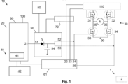
- Fig. 1 a schematic representation of an arrangement according to the invention, in particular for visualizing a method according to the invention.
- Fig. 1 Shown is an arrangement 10 according to the invention for providing an emergency braking function in a safety device 1 of a vehicle.
- the safety device 1 is designed, for example, as a steering column lock, whereby the Steering column of the vehicle can be locked by a locking element, not shown. It is possible that optionally at least one sensor 2 of the safety device 1 is provided in order to detect a position of the locking element, in particular a position for locking the steering column
- the arrangement 10 according to the invention has an electronic control arrangement 20 for controlling a drive unit 30 in order to drive a safety mechanism of the safety device 1 via the drive unit 30 in normal operation.
- the safety mechanism causes z. B. moving the locking element and/or locking the steering column.
- the control arrangement 20 can be designed to initiate braking, in particular stopping, of the drive unit 30. Braking is advantageously initiated when the sensor 2 indicates that the locking position has been reached.
- the control arrangement 20 can have one or more control units 60, 61 (e.g. each microcontroller) to provide the control.
- an electronic monitoring arrangement 40 can be used to monitor the control arrangement 20 in order to switch from normal operation to error operation depending on the monitoring. This makes it possible to activate an emergency brake arrangement 50 to initiate braking of the drive unit 30 in error operation.
- the monitoring arrangement 40 can be connected to the emergency brake arrangement 50 and can therefore be designed to carry out this activation during or after switching to error mode.
- control arrangement 20 is connected to at least four switching units 31, 32, 33, 34, in particular MOSFETs, of the drive unit 30 in order to control the switching units 31, 32, 33, 34 to set a direction of rotation of the drive unit 30.
- the connection to the respective switching units 31, 32, 33, 34 takes place via respective control outputs 22, 23, 24, 25 of the control arrangement 20, whereby the control can also take place indirectly (indirectly) via a drive control unit 110.
- the drive unit 30 is advantageously designed as a direct current motor and in particular has two connections 35, 36 of a winding, preferably an armature winding or field winding. As in Figure 1 is shown, the connections 35, 36 are connected via a respective switching unit 33, 34 to a common potential 90, preferably ground potential 90, in order to close the switching units 33, 34 to cause a short circuit in the winding for braking by the emergency brake arrangement 50.
- the emergency brake arrangement 50 can have at least two 33, 34 Switching units 31, 32, 33, 34 of the drive unit 30 can be connected in order to control them to initiate braking. Specifically, the switching units 33, 34 can be controlled to initiate the short circuit in the drive unit 30 and thus initiate the braking as short-circuit braking.
- connection of the emergency brake arrangement 50 to the at least two 33, 34 of the switching units 31, 32, 33, 34 takes place, for example, as a bridging of the control arrangement 20 via respective emergency control outputs 52, 53 directly to the respective control path of the switching units 33, 34.
- This is in Figure 1 shown by an arrow.
- a signal input 51, in particular a negated signal input 51, of the emergency brake arrangement 50 can be connected to a signal output 21 of the monitoring arrangement 40 in order to be activated by this signal input 51 in error mode.
- the emergency brake arrangement 50 can also provide an energy reserve, preferably through a capacitor 54 and/or through an, in particular electrical and/or mechanical, emergency energy storage 80, in the event of a fault, in particular in the event of a faulty main power supply 100 and/or in the event of a voltage drop in the control arrangement 20 , the braking and in particular the switching of a short circuit in the drive unit 30 to provide.
- the emergency energy storage 80 is designed, for example, as an accumulator or the like, which is charged by the main energy supply 100 during normal operation.
- a priority arrangement 70 can be connected to the control arrangement 20 and/or to the emergency brake arrangement 50 in order to provide control of at least one of the switching units 33, 34 of the drive unit 30 by the emergency brake arrangement 50 with priority to the control arrangement 20 and/or control of at least one of the switching units 31, 32 to be prevented by the control arrangement 20.
- the monitoring arrangement 40 is designed to change a signal at a signal output 21, in particular the reset output, of the control arrangement 20 in order to activate the emergency brake arrangement 50 for braking, the signal output 21 being connected to a signal input 51 of the emergency brake arrangement 50, to initiate charging of a capacitor 54 of the emergency brake arrangement 50.
- the capacitor 54 can be connected to a main power supply 100 via a diode D in order to use the electrical energy provided by the capacitor 54 to control at least one switching unit 33, 34 for switching a short circuit in the drive unit 30.
- the exemplary embodiment shown also visualizes a method according to the invention, in which, according to a first method step, a control of a drive unit 30 for driving a safety mechanism of the safety device 1 is carried out in normal operation, wherein the control also includes an initiation of braking of the drive unit 30 in normal operation. Subsequently, according to a second method step, monitoring of the control is carried out, according to a third method step, a switch from normal operation to error operation is carried out depending on the monitoring, and according to a fourth method step, an emergency brake arrangement 50 is activated only in error mode, whereby the braking of the drive unit 30 is initiated as emergency braking.
- a control of a drive unit 30 for driving a safety mechanism of the safety device 1 is carried out in normal operation, wherein the control also includes an initiation of braking of the drive unit 30 in normal operation.
- monitoring of the control is carried out
- a switch from normal operation to error operation is carried out depending on the monitoring
- an emergency brake arrangement 50 is activated only in error mode, where
Landscapes
- Engineering & Computer Science (AREA)
- Mechanical Engineering (AREA)
- Valves And Accessory Devices For Braking Systems (AREA)
- Regulating Braking Force (AREA)
Claims (13)
- Dispositif (10) pour fournir une fonction de freinage d'urgence dans un dispositif de sécurité (1) sous la forme d'un verrouillage de colonne de direction d'un véhicule, comprenant :- un dispositif de contrôle électronique (20) pour commander une unité d'entraînement (30) afin d'entraîner un mécanisme de sécurité du dispositif de sécurité (1) dans un mode normal, le dispositif de contrôle (20) étant réalisé pour initier un freinage de l'unité d'entraînement (30),- un dispositif de surveillance électronique (40) pour la surveillance du dispositif de contrôle (20), afin de passer du mode normal à un mode de défaut en fonction de la surveillance,- un dispositif de freinage d'urgence (50) pour initier le freinage de l'unité d'entraînement (30) en mode de défaut,le dispositif de surveillance (40) étant connecté au dispositif de freinage d'urgence (50) afin d'activer le dispositif de freinage d'urgence (50) pour le freinage en mode de défaut, dans lequelle dispositif de freinage d'urgence (50) est connecté à au moins deux unités de commutation électroniques (33, 34) de l'unité d'entraînement (30), afin de commander les unités de commutation (33, 34) pour initier un court-circuit dans l'unité d'entraînement (30) et ainsi initier le freinage en tant que freinage par court-circuit.
- Dispositif (10) selon la revendication 1,
caractérisé en ce que
une entrée de signal (51), en particulier une entrée de signal (51) inversée, du dispositif de freinage d'urgence (50) est reliée à une sortie de signal (21) du dispositif de surveillance (40), afin d'être activée par cette entrée de signal (51) en mode de défaut. - Dispositif (10) selon la revendication 1 ou 2,
caractérisé en ce que
l'unité d'entraînement (30) est prévue comme moteur à courant continu, et présente en particulier deux connexions (35, 36) d'un enroulement, de préférence d'un enroulement d'induit ou d'un enroulement d'excitation, qui sont reliées par une unité de commutation respective (33, 34) à un potentiel commun (90), de préférence un potentiel de masse (90), afin de fermer les unités de commutation (33, 34) pour provoquer un court-circuit dans l'enroulement pour le freinage par le dispositif de freinage d'urgence (50). - Dispositif (10) selon l'une quelconque des revendications précédentes,
caractérisé en ce que
le dispositif (10) est conçu pour fournir la fonction de freinage d'urgence dans le dispositif de sécurité (1) sous la forme d'un verrouillage de colonne de direction, et Le dispositif de contrôle (20) est conçu, par l'intermédiaire de la commande de l'unité d'entraînement (30), pour initier un mouvement d'un élément de blocage du dispositif de sécurité (1) d'une position de déverrouillage à une position de verrouillage et/ou inversement, et pour initier le freinage sous la forme d'un freinage en court-circuit de l'unité d'entraînement (30) pour arrêter complètement ce mouvement. - Dispositif (10) selon l'une quelconque des revendications précédentes,
caractérisé en ce que
le dispositif de freinage d'urgence (50) met à disposition une réserve d'énergie, de préférence par un condensateur (54) et/ou par un accumulateur d'énergie de secours (80), en particulier électrique et/ou mécanique, afin de mettre à disposition le freinage et en particulier la commutation d'un court-circuit dans l'unité d'entraînement (30) en mode de défaut, en particulier en cas d'alimentation en énergie principale (100) défectueuse et/ou en cas de chute de tension dans le dispositif de contrôle (20). - Dispositif (10) selon l'une quelconque des revendications précédentes,
caractérisé en ce que
le dispositif de contrôle (20) est relié à au moins quatre unités de commutation (31, 32, 33, 34), en particulier des MOSFET, de l'unité d'entraînement (30), afin de commander les unités de commutation (31, 32, 33, 34) pour le réglage d'un sens de rotation de l'unité d'entraînement (30), le dispositif de freinage d'urgence (50) étant relié à au moins deux (33, 34) des unités de commutation (31, 32, 33, 34), afin de commander celles-ci pour le déclenchement du freinage. - Dispositif (10) selon l'une quelconque des revendications précédentes,
caractérisé en ce qu'
un dispositif prioritaire (70) est connecté au dispositif de contrôle (20) et/ou au dispositif de freinage d'urgence (50) pour fournir une commande d'unités de commutation (31, 32, 33, 34) de l'unité d'entraînement (30) par le dispositif de freinage d'urgence (50) en priorité par rapport au dispositif de contrôle (20) et/ou pour empêcher la commande des unités de commutation (31, 32, 33, 34) par le dispositif de contrôle (20) en mode de défaut. - Dispositif (10) selon l'une quelconque des revendications précédentes,
caractérisé en ce quele dispositif de surveillance (40) présente au moins une des unités de surveillance (41, 42) suivantes :- un chien de garde (41) pour surveiller au moins une unité de contrôle (60) du dispositif de contrôle (20), de préférence un microcontrôleur (60),- une unité de surveillance de l'énergie et de préférence de la tension (42) pour surveiller une alimentation principale en énergie (100) du dispositif de contrôle (20),le dispositif de surveillance (40) étant réalisé de manière à passer en mode de défaut et/ou à activer le dispositif de freinage d'urgence (50) en mode de défaut détecté par déjà l'une des unités de surveillance (41, 42). - Dispositif (10) selon l'une quelconque des revendications précédentes,
caractérisé en ce que
le dispositif de surveillance (40) est réalisé de manière à modifier, pour activer le dispositif de freinage d'urgence (50) pour le freinage, un signal à une sortie de signal (21), en particulier une sortie de réinitialisation, du dispositif de contrôle (20), la sortie de signal (21) étant reliée à une entrée de signal (51) du dispositif de freinage d'urgence (50), pour initier une charge d'un condensateur (54) du dispositif de freinage d'urgence (50), qui est relié en particulier par l'intermédiaire d'une diode (D) à une alimentation principale en énergie (100), afin de commander par l'énergie électrique fournie par le condensateur (54) au moins une unité de commutation (33, 34) pour commuter un court-circuit de l'unité d'entraînement (30). - Dispositif (10) selon l'une quelconque des revendications précédentes,
caractérisé en ce qu'
un accumulateur d'énergie de secours (80) est relié au dispositif de freinage d'urgence (50) pour fournir une alimentation en énergie en plus de l'alimentation en énergie principale (100) du dispositif (10) pour l'initiation du freinage, en particulier pour charger un condensateur (54) du dispositif de freinage d'urgence (50). - Dispositif (10) selon l'une quelconque des revendications précédentes,
caractérisé en ce qu'
au moins un capteur (2) du dispositif de sécurité (1) est prévu pour détecter une position d'un élément de blocage, en particulier pour verrouiller une colonne de direction, et est connecté au dispositif de contrôle (20) pour initier le freinage en mode normal à l'aide de la position détectée, le dispositif de freinage d'urgence (50) étant réalisé pour initier le freinage indépendamment de la position détectée et/ou du capteur (2). - Procédé pour fournir une fonction de freinage d'urgence à un dispositif de sécurité (1) sous la forme d'un verrouillage de colonne de direction d'un véhicule, dans lequel les étapes suivantes sont effectuées :- L'exécution d'une commande d'une unité d'entraînement (30) pour entraîner un mécanisme de sécurité du dispositif de sécurité (1) dans un mode normal, la commande comprenant également l'initiation d'un freinage de l'unité d'entraînement (30) dans le mode normal,- Effectuer une surveillance de la commande,- Commutation du mode normal en mode de défaut en fonction de la surveillance,- L'activation d'un dispositiv de freinage d'urgence (50) uniquement en mode de défaut, ce qui permet d'initier le freinage de l'unité d'entraînement (30) en tant que freinage d'urgence,caractérisé en ce que
le dispositif de freinage d'urgence (50) est connecté à au moins deux unités de commutation électroniques (33, 34) de l'unité d'entraînement (30), afin de commander les unités de commutation (33, 34) pour initier un court-circuit dans l'unité d'entraînement (30) et ainsi initier le freinage comme freinage par court-circuit. - Procédé selon la revendication 12,
caractérisé en ce que
le fonctionnement en mode de défaut est spécifique au fait que l'initiation du freinage en mode normal est entravée, en particulier par une entrave à une alimentation principale en énergie (100) pour la commande, la surveillance étant effectuée de préférence pour la détection de cette entrave sous la forme d'une surveillance de la tension de l'alimentation principale en énergie (100).
Applications Claiming Priority (1)
| Application Number | Priority Date | Filing Date | Title |
|---|---|---|---|
| DE102018122140.1A DE102018122140A1 (de) | 2018-09-11 | 2018-09-11 | Anordnung zur Bereitstellung einer Notbremsfunktion bei einer Sicherheitsvorrichtung eines Fahrzeuges |
Publications (2)
| Publication Number | Publication Date |
|---|---|
| EP3623231A1 EP3623231A1 (fr) | 2020-03-18 |
| EP3623231B1 true EP3623231B1 (fr) | 2024-03-13 |
Family
ID=67847609
Family Applications (1)
| Application Number | Title | Priority Date | Filing Date |
|---|---|---|---|
| EP19195045.0A Active EP3623231B1 (fr) | 2018-09-11 | 2019-09-03 | Dispositif de fourniture d'une fonction de freinage d'urgence sur un dispositif de sécurité d'un véhicule |
Country Status (2)
| Country | Link |
|---|---|
| EP (1) | EP3623231B1 (fr) |
| DE (1) | DE102018122140A1 (fr) |
Citations (1)
| Publication number | Priority date | Publication date | Assignee | Title |
|---|---|---|---|---|
| DE102013113317A1 (de) * | 2012-12-20 | 2014-06-26 | U-Shin Ltd. | Elektrisch betätigte Lenkschloßeinrichtung |
Family Cites Families (3)
| Publication number | Priority date | Publication date | Assignee | Title |
|---|---|---|---|---|
| FR2801263A1 (fr) * | 1999-11-19 | 2001-05-25 | Siemens Automotive Sa | Dispositif de verrouillage d'un arbre de transmission d'un vehicule automobile |
| SE526547C2 (sv) * | 2003-11-18 | 2005-10-04 | Saab Automobile | Nyckelstyrning av strömriktningsberoende anordning |
| JP5587749B2 (ja) * | 2010-11-25 | 2014-09-10 | 株式会社ユーシン | 電動ステアリングロック装置 |
-
2018
- 2018-09-11 DE DE102018122140.1A patent/DE102018122140A1/de not_active Withdrawn
-
2019
- 2019-09-03 EP EP19195045.0A patent/EP3623231B1/fr active Active
Patent Citations (1)
| Publication number | Priority date | Publication date | Assignee | Title |
|---|---|---|---|---|
| DE102013113317A1 (de) * | 2012-12-20 | 2014-06-26 | U-Shin Ltd. | Elektrisch betätigte Lenkschloßeinrichtung |
Also Published As
| Publication number | Publication date |
|---|---|
| DE102018122140A1 (de) | 2020-03-12 |
| EP3623231A1 (fr) | 2020-03-18 |
Similar Documents
| Publication | Publication Date | Title |
|---|---|---|
| EP2084421B1 (fr) | Ensemble d'actionneur pour un embrayage de vehicule automobile | |
| DE102010033440B4 (de) | Verfahren und Vorrichtung zur Sicherheitsabschaltung einer elektromechanischen Servolenkung | |
| DE102014016017B4 (de) | Fahrzeug-Lenkvorrichtung mit einer Lenkradhemmung | |
| DE102014204287A1 (de) | Verfahren zum Betreiben einer Kraftfahrzeugbremseinrichtung sowie Steuergerät für eine Kraftfahrzeugbremseinrichtung | |
| WO2016015954A1 (fr) | Dispositif servant à surveiller la présence éventuelle d'une surcharge dans un réseau de bord à haute tension d'un véhicule à fonctionnement électrique | |
| WO2015082113A1 (fr) | Réseau de bord pour alimentation redondante à tolérance aux défauts | |
| EP3592611B1 (fr) | Véhicule utilitaire et procédé de fonctionnement d'un véhicule utilitaire | |
| DE102017222484A1 (de) | Verfahren und Vorrichtung für eine hochverfügbare automatische Parkbremse | |
| EP3747733B1 (fr) | Procédé de fonctionnement d'un système de direction | |
| EP2608996B1 (fr) | Circuit de sécurité pour un moteur électrique d'une direction électromécanique | |
| EP4273025A1 (fr) | Système de direction à commande par câble et procédé permettant de faire fonctionner un système de direction à commande par câble dans un mode de fonctionnement normal et dans un mode de fonctionnement spécial | |
| WO2015039658A1 (fr) | Procédé permettant d'alimenter un appareil de commande | |
| DE102015107718A1 (de) | Vorrichtung und Verfahren zum Absichern einer Bordnetz-Komponente eines Fahrzeug-Bordnetzes | |
| EP4347338B1 (fr) | Systeme de freinage electromecanique pour vehicule automobile, procede | |
| DE102016004218A1 (de) | Wegfahrsperrenanordnung eines Kraftfahrzeugs, Kraftfahrzeug sowie Verfahren zur Betätigung einer Wegfahrsperrenanordnung | |
| EP4347337B1 (fr) | Systeme de freinage electromecanique pour vehicule automobile, procede | |
| EP4347332B1 (fr) | Système de freinage électromécanique pour véhicule automobile et procédé de commande associé | |
| EP1985522B1 (fr) | Dispositif de protection pour une direction assistée | |
| EP3623231B1 (fr) | Dispositif de fourniture d'une fonction de freinage d'urgence sur un dispositif de sécurité d'un véhicule | |
| DE102018125308A1 (de) | Feststellbremse eines zweispurigen Fahrzeuges und Verfahren zum Betreiben einer Festellbremse | |
| WO2011047952A1 (fr) | Dispositif de contrôle pour un réseau électrique haute tension d'un véhicule | |
| DE10116925C1 (de) | Kraftfahrzeug mit einem Spannungsnetz | |
| EP2559602A2 (fr) | Procédé et dispositif destiné à bloquer la traction d'un véhicule ferroviaire arrêté | |
| DE102022125767A1 (de) | Fahrzeugkomponente mit einer Lenkvorgabeeinrichtung zum Vorgeben eines Lenkbefehls nach dem Steer-by-Wire-Konzept und Verfahren | |
| DE102022203853A1 (de) | Verfahren und Vorrichtung zum Abbremsen eines Fahrzeugs bei Ausfall der Bremsensteuerung |
Legal Events
| Date | Code | Title | Description |
|---|---|---|---|
| PUAI | Public reference made under article 153(3) epc to a published international application that has entered the european phase |
Free format text: ORIGINAL CODE: 0009012 |
|
| STAA | Information on the status of an ep patent application or granted ep patent |
Free format text: STATUS: THE APPLICATION HAS BEEN PUBLISHED |
|
| AK | Designated contracting states |
Kind code of ref document: A1 Designated state(s): AL AT BE BG CH CY CZ DE DK EE ES FI FR GB GR HR HU IE IS IT LI LT LU LV MC MK MT NL NO PL PT RO RS SE SI SK SM TR |
|
| AX | Request for extension of the european patent |
Extension state: BA ME |
|
| STAA | Information on the status of an ep patent application or granted ep patent |
Free format text: STATUS: REQUEST FOR EXAMINATION WAS MADE |
|
| 17P | Request for examination filed |
Effective date: 20200918 |
|
| RBV | Designated contracting states (corrected) |
Designated state(s): AL AT BE BG CH CY CZ DE DK EE ES FI FR GB GR HR HU IE IS IT LI LT LU LV MC MK MT NL NO PL PT RO RS SE SI SK SM TR |
|
| STAA | Information on the status of an ep patent application or granted ep patent |
Free format text: STATUS: EXAMINATION IS IN PROGRESS |
|
| 17Q | First examination report despatched |
Effective date: 20210916 |
|
| GRAP | Despatch of communication of intention to grant a patent |
Free format text: ORIGINAL CODE: EPIDOSNIGR1 |
|
| STAA | Information on the status of an ep patent application or granted ep patent |
Free format text: STATUS: GRANT OF PATENT IS INTENDED |
|
| INTG | Intention to grant announced |
Effective date: 20231006 |
|
| GRAS | Grant fee paid |
Free format text: ORIGINAL CODE: EPIDOSNIGR3 |
|
| GRAA | (expected) grant |
Free format text: ORIGINAL CODE: 0009210 |
|
| STAA | Information on the status of an ep patent application or granted ep patent |
Free format text: STATUS: THE PATENT HAS BEEN GRANTED |
|
| AK | Designated contracting states |
Kind code of ref document: B1 Designated state(s): AL AT BE BG CH CY CZ DE DK EE ES FI FR GB GR HR HU IE IS IT LI LT LU LV MC MK MT NL NO PL PT RO RS SE SI SK SM TR |
|
| REG | Reference to a national code |
Ref country code: GB Ref legal event code: FG4D Free format text: NOT ENGLISH |
|
| REG | Reference to a national code |
Ref country code: CH Ref legal event code: EP |
|
| P01 | Opt-out of the competence of the unified patent court (upc) registered |
Effective date: 20240214 |
|
| REG | Reference to a national code |
Ref country code: DE Ref legal event code: R096 Ref document number: 502019010771 Country of ref document: DE |
|
| REG | Reference to a national code |
Ref country code: IE Ref legal event code: FG4D Free format text: LANGUAGE OF EP DOCUMENT: GERMAN |
|
| PG25 | Lapsed in a contracting state [announced via postgrant information from national office to epo] |
Ref country code: LT Free format text: LAPSE BECAUSE OF FAILURE TO SUBMIT A TRANSLATION OF THE DESCRIPTION OR TO PAY THE FEE WITHIN THE PRESCRIBED TIME-LIMIT Effective date: 20240313 |
|
| REG | Reference to a national code |
Ref country code: LT Ref legal event code: MG9D |
|
| PG25 | Lapsed in a contracting state [announced via postgrant information from national office to epo] |
Ref country code: GR Free format text: LAPSE BECAUSE OF FAILURE TO SUBMIT A TRANSLATION OF THE DESCRIPTION OR TO PAY THE FEE WITHIN THE PRESCRIBED TIME-LIMIT Effective date: 20240614 |
|
| REG | Reference to a national code |
Ref country code: NL Ref legal event code: MP Effective date: 20240313 |
|
| PG25 | Lapsed in a contracting state [announced via postgrant information from national office to epo] |
Ref country code: HR Free format text: LAPSE BECAUSE OF FAILURE TO SUBMIT A TRANSLATION OF THE DESCRIPTION OR TO PAY THE FEE WITHIN THE PRESCRIBED TIME-LIMIT Effective date: 20240313 Ref country code: RS Free format text: LAPSE BECAUSE OF FAILURE TO SUBMIT A TRANSLATION OF THE DESCRIPTION OR TO PAY THE FEE WITHIN THE PRESCRIBED TIME-LIMIT Effective date: 20240613 |
|
| PG25 | Lapsed in a contracting state [announced via postgrant information from national office to epo] |
Ref country code: ES Free format text: LAPSE BECAUSE OF FAILURE TO SUBMIT A TRANSLATION OF THE DESCRIPTION OR TO PAY THE FEE WITHIN THE PRESCRIBED TIME-LIMIT Effective date: 20240313 |
|
| PG25 | Lapsed in a contracting state [announced via postgrant information from national office to epo] |
Ref country code: RS Free format text: LAPSE BECAUSE OF FAILURE TO SUBMIT A TRANSLATION OF THE DESCRIPTION OR TO PAY THE FEE WITHIN THE PRESCRIBED TIME-LIMIT Effective date: 20240613 Ref country code: NO Free format text: LAPSE BECAUSE OF FAILURE TO SUBMIT A TRANSLATION OF THE DESCRIPTION OR TO PAY THE FEE WITHIN THE PRESCRIBED TIME-LIMIT Effective date: 20240613 Ref country code: LT Free format text: LAPSE BECAUSE OF FAILURE TO SUBMIT A TRANSLATION OF THE DESCRIPTION OR TO PAY THE FEE WITHIN THE PRESCRIBED TIME-LIMIT Effective date: 20240313 Ref country code: HR Free format text: LAPSE BECAUSE OF FAILURE TO SUBMIT A TRANSLATION OF THE DESCRIPTION OR TO PAY THE FEE WITHIN THE PRESCRIBED TIME-LIMIT Effective date: 20240313 Ref country code: GR Free format text: LAPSE BECAUSE OF FAILURE TO SUBMIT A TRANSLATION OF THE DESCRIPTION OR TO PAY THE FEE WITHIN THE PRESCRIBED TIME-LIMIT Effective date: 20240614 Ref country code: FI Free format text: LAPSE BECAUSE OF FAILURE TO SUBMIT A TRANSLATION OF THE DESCRIPTION OR TO PAY THE FEE WITHIN THE PRESCRIBED TIME-LIMIT Effective date: 20240313 Ref country code: ES Free format text: LAPSE BECAUSE OF FAILURE TO SUBMIT A TRANSLATION OF THE DESCRIPTION OR TO PAY THE FEE WITHIN THE PRESCRIBED TIME-LIMIT Effective date: 20240313 Ref country code: BG Free format text: LAPSE BECAUSE OF FAILURE TO SUBMIT A TRANSLATION OF THE DESCRIPTION OR TO PAY THE FEE WITHIN THE PRESCRIBED TIME-LIMIT Effective date: 20240313 |
|
| PG25 | Lapsed in a contracting state [announced via postgrant information from national office to epo] |
Ref country code: SE Free format text: LAPSE BECAUSE OF FAILURE TO SUBMIT A TRANSLATION OF THE DESCRIPTION OR TO PAY THE FEE WITHIN THE PRESCRIBED TIME-LIMIT Effective date: 20240313 Ref country code: LV Free format text: LAPSE BECAUSE OF FAILURE TO SUBMIT A TRANSLATION OF THE DESCRIPTION OR TO PAY THE FEE WITHIN THE PRESCRIBED TIME-LIMIT Effective date: 20240313 |
|
| PG25 | Lapsed in a contracting state [announced via postgrant information from national office to epo] |
Ref country code: NL Free format text: LAPSE BECAUSE OF FAILURE TO SUBMIT A TRANSLATION OF THE DESCRIPTION OR TO PAY THE FEE WITHIN THE PRESCRIBED TIME-LIMIT Effective date: 20240313 |
|
| PG25 | Lapsed in a contracting state [announced via postgrant information from national office to epo] |
Ref country code: NL Free format text: LAPSE BECAUSE OF FAILURE TO SUBMIT A TRANSLATION OF THE DESCRIPTION OR TO PAY THE FEE WITHIN THE PRESCRIBED TIME-LIMIT Effective date: 20240313 |
|
| PG25 | Lapsed in a contracting state [announced via postgrant information from national office to epo] |
Ref country code: IS Free format text: LAPSE BECAUSE OF FAILURE TO SUBMIT A TRANSLATION OF THE DESCRIPTION OR TO PAY THE FEE WITHIN THE PRESCRIBED TIME-LIMIT Effective date: 20240713 |
|
| PG25 | Lapsed in a contracting state [announced via postgrant information from national office to epo] |
Ref country code: PT Free format text: LAPSE BECAUSE OF FAILURE TO SUBMIT A TRANSLATION OF THE DESCRIPTION OR TO PAY THE FEE WITHIN THE PRESCRIBED TIME-LIMIT Effective date: 20240715 Ref country code: SM Free format text: LAPSE BECAUSE OF FAILURE TO SUBMIT A TRANSLATION OF THE DESCRIPTION OR TO PAY THE FEE WITHIN THE PRESCRIBED TIME-LIMIT Effective date: 20240313 |
|
| PG25 | Lapsed in a contracting state [announced via postgrant information from national office to epo] |
Ref country code: EE Free format text: LAPSE BECAUSE OF FAILURE TO SUBMIT A TRANSLATION OF THE DESCRIPTION OR TO PAY THE FEE WITHIN THE PRESCRIBED TIME-LIMIT Effective date: 20240313 Ref country code: CZ Free format text: LAPSE BECAUSE OF FAILURE TO SUBMIT A TRANSLATION OF THE DESCRIPTION OR TO PAY THE FEE WITHIN THE PRESCRIBED TIME-LIMIT Effective date: 20240313 |
|
| PG25 | Lapsed in a contracting state [announced via postgrant information from national office to epo] |
Ref country code: PL Free format text: LAPSE BECAUSE OF FAILURE TO SUBMIT A TRANSLATION OF THE DESCRIPTION OR TO PAY THE FEE WITHIN THE PRESCRIBED TIME-LIMIT Effective date: 20240313 |
|
| PG25 | Lapsed in a contracting state [announced via postgrant information from national office to epo] |
Ref country code: SK Free format text: LAPSE BECAUSE OF FAILURE TO SUBMIT A TRANSLATION OF THE DESCRIPTION OR TO PAY THE FEE WITHIN THE PRESCRIBED TIME-LIMIT Effective date: 20240313 |
|
| PG25 | Lapsed in a contracting state [announced via postgrant information from national office to epo] |
Ref country code: SM Free format text: LAPSE BECAUSE OF FAILURE TO SUBMIT A TRANSLATION OF THE DESCRIPTION OR TO PAY THE FEE WITHIN THE PRESCRIBED TIME-LIMIT Effective date: 20240313 Ref country code: SK Free format text: LAPSE BECAUSE OF FAILURE TO SUBMIT A TRANSLATION OF THE DESCRIPTION OR TO PAY THE FEE WITHIN THE PRESCRIBED TIME-LIMIT Effective date: 20240313 Ref country code: RO Free format text: LAPSE BECAUSE OF FAILURE TO SUBMIT A TRANSLATION OF THE DESCRIPTION OR TO PAY THE FEE WITHIN THE PRESCRIBED TIME-LIMIT Effective date: 20240313 Ref country code: PT Free format text: LAPSE BECAUSE OF FAILURE TO SUBMIT A TRANSLATION OF THE DESCRIPTION OR TO PAY THE FEE WITHIN THE PRESCRIBED TIME-LIMIT Effective date: 20240715 Ref country code: PL Free format text: LAPSE BECAUSE OF FAILURE TO SUBMIT A TRANSLATION OF THE DESCRIPTION OR TO PAY THE FEE WITHIN THE PRESCRIBED TIME-LIMIT Effective date: 20240313 Ref country code: IS Free format text: LAPSE BECAUSE OF FAILURE TO SUBMIT A TRANSLATION OF THE DESCRIPTION OR TO PAY THE FEE WITHIN THE PRESCRIBED TIME-LIMIT Effective date: 20240713 Ref country code: EE Free format text: LAPSE BECAUSE OF FAILURE TO SUBMIT A TRANSLATION OF THE DESCRIPTION OR TO PAY THE FEE WITHIN THE PRESCRIBED TIME-LIMIT Effective date: 20240313 Ref country code: CZ Free format text: LAPSE BECAUSE OF FAILURE TO SUBMIT A TRANSLATION OF THE DESCRIPTION OR TO PAY THE FEE WITHIN THE PRESCRIBED TIME-LIMIT Effective date: 20240313 |
|
| PG25 | Lapsed in a contracting state [announced via postgrant information from national office to epo] |
Ref country code: IT Free format text: LAPSE BECAUSE OF FAILURE TO SUBMIT A TRANSLATION OF THE DESCRIPTION OR TO PAY THE FEE WITHIN THE PRESCRIBED TIME-LIMIT Effective date: 20240313 |
|
| REG | Reference to a national code |
Ref country code: DE Ref legal event code: R097 Ref document number: 502019010771 Country of ref document: DE |
|
| PG25 | Lapsed in a contracting state [announced via postgrant information from national office to epo] |
Ref country code: IT Free format text: LAPSE BECAUSE OF FAILURE TO SUBMIT A TRANSLATION OF THE DESCRIPTION OR TO PAY THE FEE WITHIN THE PRESCRIBED TIME-LIMIT Effective date: 20240313 |
|
| PG25 | Lapsed in a contracting state [announced via postgrant information from national office to epo] |
Ref country code: DK Free format text: LAPSE BECAUSE OF FAILURE TO SUBMIT A TRANSLATION OF THE DESCRIPTION OR TO PAY THE FEE WITHIN THE PRESCRIBED TIME-LIMIT Effective date: 20240313 |
|
| PLBE | No opposition filed within time limit |
Free format text: ORIGINAL CODE: 0009261 |
|
| STAA | Information on the status of an ep patent application or granted ep patent |
Free format text: STATUS: NO OPPOSITION FILED WITHIN TIME LIMIT |
|
| PG25 | Lapsed in a contracting state [announced via postgrant information from national office to epo] |
Ref country code: DK Free format text: LAPSE BECAUSE OF FAILURE TO SUBMIT A TRANSLATION OF THE DESCRIPTION OR TO PAY THE FEE WITHIN THE PRESCRIBED TIME-LIMIT Effective date: 20240313 |
|
| 26N | No opposition filed |
Effective date: 20241216 |
|
| PG25 | Lapsed in a contracting state [announced via postgrant information from national office to epo] |
Ref country code: MC Free format text: LAPSE BECAUSE OF FAILURE TO SUBMIT A TRANSLATION OF THE DESCRIPTION OR TO PAY THE FEE WITHIN THE PRESCRIBED TIME-LIMIT Effective date: 20240313 Ref country code: SI Free format text: LAPSE BECAUSE OF FAILURE TO SUBMIT A TRANSLATION OF THE DESCRIPTION OR TO PAY THE FEE WITHIN THE PRESCRIBED TIME-LIMIT Effective date: 20240313 |
|
| REG | Reference to a national code |
Ref country code: CH Ref legal event code: PL |
|
| PG25 | Lapsed in a contracting state [announced via postgrant information from national office to epo] |
Ref country code: LU Free format text: LAPSE BECAUSE OF NON-PAYMENT OF DUE FEES Effective date: 20240903 |
|
| GBPC | Gb: european patent ceased through non-payment of renewal fee |
Effective date: 20240903 |
|
| PG25 | Lapsed in a contracting state [announced via postgrant information from national office to epo] |
Ref country code: GB Free format text: LAPSE BECAUSE OF NON-PAYMENT OF DUE FEES Effective date: 20240903 |
|
| REG | Reference to a national code |
Ref country code: BE Ref legal event code: MM Effective date: 20240930 |
|
| PG25 | Lapsed in a contracting state [announced via postgrant information from national office to epo] |
Ref country code: BE Free format text: LAPSE BECAUSE OF NON-PAYMENT OF DUE FEES Effective date: 20240930 |
|
| PG25 | Lapsed in a contracting state [announced via postgrant information from national office to epo] |
Ref country code: CH Free format text: LAPSE BECAUSE OF NON-PAYMENT OF DUE FEES Effective date: 20240930 |
|
| PG25 | Lapsed in a contracting state [announced via postgrant information from national office to epo] |
Ref country code: IE Free format text: LAPSE BECAUSE OF NON-PAYMENT OF DUE FEES Effective date: 20240903 |
|
| PGFP | Annual fee paid to national office [announced via postgrant information from national office to epo] |
Ref country code: DE Payment date: 20250930 Year of fee payment: 7 |
|
| PGFP | Annual fee paid to national office [announced via postgrant information from national office to epo] |
Ref country code: FR Payment date: 20250924 Year of fee payment: 7 |
|
| REG | Reference to a national code |
Ref country code: AT Ref legal event code: MM01 Ref document number: 1665479 Country of ref document: AT Kind code of ref document: T Effective date: 20240903 |
|
| PG25 | Lapsed in a contracting state [announced via postgrant information from national office to epo] |
Ref country code: AT Free format text: LAPSE BECAUSE OF NON-PAYMENT OF DUE FEES Effective date: 20240903 |
|
| PG25 | Lapsed in a contracting state [announced via postgrant information from national office to epo] |
Ref country code: CY Free format text: LAPSE BECAUSE OF FAILURE TO SUBMIT A TRANSLATION OF THE DESCRIPTION OR TO PAY THE FEE WITHIN THE PRESCRIBED TIME-LIMIT; INVALID AB INITIO Effective date: 20190903 |
|
| PG25 | Lapsed in a contracting state [announced via postgrant information from national office to epo] |
Ref country code: HU Free format text: LAPSE BECAUSE OF FAILURE TO SUBMIT A TRANSLATION OF THE DESCRIPTION OR TO PAY THE FEE WITHIN THE PRESCRIBED TIME-LIMIT; INVALID AB INITIO Effective date: 20190903 |