EP3623251A1 - Dispositif stabilisateur pour véhicules ferroviaires, en particulier stabilisateur de roulis - Google Patents
Dispositif stabilisateur pour véhicules ferroviaires, en particulier stabilisateur de roulis Download PDFInfo
- Publication number
- EP3623251A1 EP3623251A1 EP19193998.2A EP19193998A EP3623251A1 EP 3623251 A1 EP3623251 A1 EP 3623251A1 EP 19193998 A EP19193998 A EP 19193998A EP 3623251 A1 EP3623251 A1 EP 3623251A1
- Authority
- EP
- European Patent Office
- Prior art keywords
- stabilizer device
- coupling
- coupling element
- arrangement
- fastening
- Prior art date
- Legal status (The legal status is an assumption and is not a legal conclusion. Google has not performed a legal analysis and makes no representation as to the accuracy of the status listed.)
- Granted
Links
Images


Classifications
-
- B—PERFORMING OPERATIONS; TRANSPORTING
- B61—RAILWAYS
- B61G—COUPLINGS; DRAUGHT AND BUFFING APPLIANCES
- B61G5/00—Couplings for special purposes not otherwise provided for
- B61G5/02—Couplings for special purposes not otherwise provided for for coupling articulated trains, locomotives and tenders or the bogies of a vehicle; Coupling by means of a single coupling bar; Couplings preventing or limiting relative lateral movement of vehicles
-
- F—MECHANICAL ENGINEERING; LIGHTING; HEATING; WEAPONS; BLASTING
- F16—ENGINEERING ELEMENTS AND UNITS; GENERAL MEASURES FOR PRODUCING AND MAINTAINING EFFECTIVE FUNCTIONING OF MACHINES OR INSTALLATIONS; THERMAL INSULATION IN GENERAL
- F16F—SPRINGS; SHOCK-ABSORBERS; MEANS FOR DAMPING VIBRATION
- F16F1/00—Springs
- F16F1/36—Springs made of rubber or other material having high internal friction, e.g. thermoplastic elastomers
- F16F1/38—Springs made of rubber or other material having high internal friction, e.g. thermoplastic elastomers with a sleeve of elastic material between a rigid outer sleeve and a rigid inner sleeve or pin, i.e. bushing-type
- F16F1/3807—Springs made of rubber or other material having high internal friction, e.g. thermoplastic elastomers with a sleeve of elastic material between a rigid outer sleeve and a rigid inner sleeve or pin, i.e. bushing-type characterised by adaptations for particular modes of stressing
- F16F1/3821—Springs made of rubber or other material having high internal friction, e.g. thermoplastic elastomers with a sleeve of elastic material between a rigid outer sleeve and a rigid inner sleeve or pin, i.e. bushing-type characterised by adaptations for particular modes of stressing characterised by adaptations to counter torsional forces
-
- F—MECHANICAL ENGINEERING; LIGHTING; HEATING; WEAPONS; BLASTING
- F16—ENGINEERING ELEMENTS AND UNITS; GENERAL MEASURES FOR PRODUCING AND MAINTAINING EFFECTIVE FUNCTIONING OF MACHINES OR INSTALLATIONS; THERMAL INSULATION IN GENERAL
- F16F—SPRINGS; SHOCK-ABSORBERS; MEANS FOR DAMPING VIBRATION
- F16F1/00—Springs
- F16F1/36—Springs made of rubber or other material having high internal friction, e.g. thermoplastic elastomers
- F16F1/38—Springs made of rubber or other material having high internal friction, e.g. thermoplastic elastomers with a sleeve of elastic material between a rigid outer sleeve and a rigid inner sleeve or pin, i.e. bushing-type
- F16F1/3828—End stop features or buffering
Definitions
- the invention relates to a stabilizer device for arrangement between two car bodies of a vehicle, in particular the invention relates to a roll stabilizer or pitch stabilizer for arrangement in the roof area between the car bodies of a rail vehicle, comprising a first fastening body for arrangement on a first car body and a second fastening body for arrangement on a second Car body, further comprising a coupling element with which the two fastening bodies and thus the two car bodies are coupled to one another.
- the EP 2 765 050 B1 discloses a stabilizer device for arrangement between two car bodies of a rail vehicle, and the stabilizer device has fastening bodies for arrangement on the respective car body.
- a coupling element is arranged between the fastening bodies, via which fastening bodies and thus the car bodies are connected to one another in order to dampen, limit and / or at least reduce roll movements, but possibly also pitch movements between the car bodies.
- the fastening bodies are formed from leaf springs, and if there are rolling movements between the car bodies, elastic deformations are caused in the leaf springs, as a result of which the desired damping and / or stabilizer effect is achieved.
- damper elements are arranged in addition to the leaf springs, which extend between an angle piece arranged on the car body and the fastening bodies in a connection point to the coupling element, and if an elastic deformation is generated in the leaf springs, this can be done can also be dampened by one or more dampers.
- a stabilizer device which is primarily intended to dampen and thus reduce roll movements between the car bodies of a rail vehicle.
- a stabilizer device is particularly necessary since the articulated bearing located underneath must between the car bodies absorb all the forces that occur between the car bodies in both the radial and axial directions.
- Stabilizer devices are unavoidable in order to dampen and limit rotation of the spherical bearing during roll movements between the car bodies, and in addition to roll movements, pitching movements between the car bodies can also be damped.
- the object of the invention is the further development and improvement of a stabilizer device for arrangement between two car bodies of a rail vehicle, and the stabilizer device should be carried out maintenance-free and inexpensively.
- the arrangement of a fluid damper should be avoided, and the stop of the stabilizer device to limit the roll movement should be made as robust as possible.
- the invention includes the technical teaching that the fastening bodies each have a flange part for arrangement on the car body and a coupling part for receiving and connecting the coupling element, and the flange part and the coupling part are connected to one another by means of a swivel joint.
- the central idea of the invention is the arrangement of a swivel joint as part of the fastening body, and the fastening body is made in two parts, namely with a flange part for arrangement on the car body on the one hand and with a coupling part for arrangement on the coupling element on the other.
- the swivel joint can be designed with a predeterminable elastic flexibility, and the swivel joint is preferably also designed with a stop so that the functions of the force build-up can take place via the rolling movement in the swivel joint.
- a stabilizer device according to the invention can also be designed for road vehicles with at least two car bodies.
- the pivot joint has a damping means with particular advantage.
- the damping means serves to produce an elastic flexibility in the rotational movement of the flange part relative to the coupling part, wherein the damping means can also form the swivel joint itself.
- the damping means can comprise an elastic body, for example a rubber material, a rubber body and / or an elastomer, which is suitable for serving as an elastic body.
- the swivel joint has an articulation axis which is designed with a course transverse to the course of a longitudinal axis of the coupling element.
- the axis of rotation forms an axis in which the coupling part can be rotated relative to the flange part. If the longitudinal axis of the coupling element extends, for example, horizontally between the car bodies of the rail vehicle transversely to the direction of travel, the articulated axes in the swivel joints of the fastening bodies can run vertically.
- the longitudinal axis which lies in the coupling element itself and indicates the extension axis of the coupling element, does not have to have an intersection with the joint axes, in particular since the coupling element is connected to end sides of the coupling part, which end sides are formed opposite the swivel joint in which the coupling part is also involved .
- the coupling element is movably connected to the respective coupling part of the fastening body by means of a coupling joint.
- the coupling joint in particular forms a ball joint, so that the coupling element has, for example, a coupling joint on both end sides, to which the respective coupling parts of the fastening bodies are connected in a ball-and-socket manner.
- the coupling element is adjustable in length. This allows an adjustment of the Stabilizer device take place, for example to set a zero position of the car bodies of the rail vehicle to each other.
- the length of the coupling element can be adjusted, for example, by means of a thread arrangement.
- the coupling element has a threaded rod for this purpose, the threaded rod comprising a first threaded area with a left-hand thread and a second, opposite threaded area with a right-hand thread, and end elements of the coupling element are screwed onto the threaded areas.
- the swivel joint furthermore has a sleeve body and an axle body, the elastic body forming the damping means being introduced between the sleeve body and the axle body.
- the sleeve body can be made in one piece with the coupling part, and it is also conceivable that the shaft body is made in one piece with the flange part. It is particularly advantageous for the sleeve body to be fixed in the coupling part and for the axle body to be fixed in the flange part, so that both the sleeve body and the axle body are designed as respective individual elements and are connected to one another by means of the elastic body.
- the swivel joint can also be arranged detachably on the coupling part and on the flange part, for example the swivel joint can be pressed into the coupling part, so that the swivel joint can be replaced in the event of maintenance.
- the detachable arrangement of the swivel joint in the coupling part can transmit the forces that occur.
- the swivel joint is advantageously formed in such a way that a rotation limitation is introduced between the sleeve body and the axle body, so that the articulated rotation movement of the coupling part to the flange part is thus limited to a predeterminable angular range is.
- the rotation limiter has at least one projection which is formed on the sleeve body and points inward in the direction of the axis body and which projects into at least one recess made in the axis body, the recess being made wider in the circumferential direction than the width of the projection.
- the desired maximum twisting movement can be set by the dimension of the gap in the circumferential direction between the projection and the recess. In particular, the maximum desired roll angle between the two car bodies can thus be set.
- the joint-integrated rotation limiter is very robust with the projection and the recess and can transmit high forces.
- a rotation limitation can be attached above the sleeve body and the axle body in diametrically opposite positions, and if the projections come to rest in the inside of the recess, such an engagement takes place in diametrically opposite positions, so that ultimately no transverse forces or other moments be introduced into the swivel.
- An advantageous embodiment of the flange part provides that the flange part is fork-shaped and receives the axle body between two fork legs of the flange part in the hinge axis.
- the fork legs can have non-circular receiving openings for receiving the axle body, into the openings on the axle body existing mounting pins are inserted and are complementary to the non-circular mounting openings, so that rotation of the axle body around the hinge axis is prevented.
- the non-circular configuration can take on an elliptical, polygonal or other configuration, for example.
- the at least one elastic body is vulcanized into a circumferential gap between the sleeve body and the axle body on at least one peripheral section. This results in a liability of the elastic body on the outside of the axle body and on the inside of the sleeve body, which is so strong that the large torsional moments can be transmitted between the flange part and the coupling part.
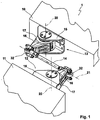
- Figure 1 shows in a perspective view a stabilizer device 1, which is arranged between two car bodies 10 and 11 of a rail vehicle.
- the arrangement of the stabilizer device 1 is preferably located in the roof area of a transition between the car bodies 10 and 11 and is attached to the respective end faces of the car bodies 10, 11.
- the stabilizer device 1 has a first fastening body 12 for mounting on the first car body 11 and a second mounting body 13, for example of identical construction, for mounting on the second car body 10.
- a coupling element 14 extends between the two fastening bodies 12 and 13, with which the two fastening bodies 12 and 13 are coupled to one another in an articulated manner.
- the coupling element 14 is connected to the fastening bodies 12 and 13 via coupling joints 32, which are designed as ball joints.
- the car bodies 10 and 11 can thus perform both a rolling movement and a pitching movement and a kinking movement with respect to one another, wherein an offset movement of the car bodies 10 and 11 is also possible without tension in the stabilizer device 1.
- the fastening bodies 12 and 13 are constructed in several parts and have a flange part 15 for arrangement on the respective car body 10, 11 and a coupling part 16 for connecting the coupling element 14. There is a swivel joint 17 between the flange part 15 and the coupling part 16.
- the respective swivel joint 17 of the two fastening bodies 12, 13 has an articulation axis 20 which is designed with a course transverse to the course of the longitudinal axis 21 of the coupling element. In particular, the hinge axes 20 run in the vertical direction.
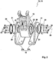
- Figure 2 shows a perspective view of the fastening bodies 12, 13 in an unassembled arrangement, and the fastening bodies 12, 13 have fork legs 15a and 15b, which are designed, for example, as angle plates, between which an axle body 23 is accommodated.
- the coupling part 16 is formed with a large receiving eye through which the axle body 23 extends.
- the axle body 23 has receiving pins 28 on its respective axial end sides, and the receiving pins 28 are introduced into receiving openings 27 which are formed in the fork legs 15a and 15b.
- the receiving openings 27 have a non-circular contour, and the receiving pins 28 are also designed to be non-round complementary to the non-round contour, so that rotation of the axle body 23 in the joint axis 20 is prevented when the receiving pins 28 are inserted into the receiving openings 27.
- the receiving openings 27 and the receiving pin 28 are oval or elliptical.
- cover elements 29 are provided which are screwed axially with screw elements 30 on the respective fork legs 15a and 15b and the axle body 23, furthermore sealing elements 31 between the cover elements 29 and the side surfaces of the Fork legs 15a, 15b are arranged.
- the rotary joint 17 is formed, which in the Figure 3 in one perspective and in the Figure 4 is shown in more detail in a sectional view.
- the swivel joint 17 is formed by the sleeve body 22 and the axle body 23, wherein the axle body 23 extends through the sleeve body 22.
- An elastic body 19 is introduced, in particular vulcanized, into the circumferential radial gap formed in this way between the axle body 23 and the sleeve body 22, and by applying a torsional force to the sleeve body 22, the latter can move relative to the axle body 23 with elastic deformation of the elastic body 19 about the hinge axis 20 be twisted.
- the elastic body 19 forms a damping means 18, and the greater the angle of rotation of the sleeve body 22 relative to the axle body 23 in the joint axis 20, the greater the torsional force that must be applied in order to continue the rotation.
- the rotation limits 24 have projections 25 which protrude radially inwards into the circumferential gap, and the projections 25 are made so deep that they protrude into recesses 26 which are at a complementary location Arrangement of the projections 25 in the axle body 23 are introduced, for example as longitudinal grooves on the outer circumference. If the sleeve body 22 is rotated relative to the axle body 23, the side flanks of the projections 25 reach the side wall of the recesses 26 at a defined angle of rotation, as a result of which a solid stop between the sleeve body 22 and the axle body 23 is achieved in the circumferential direction.
- the dimension of the gap in the circumferential direction between the projections 25 and the recesses 26 defines the maximum twisting movement before the solid stop occurs. Due to the diametrically opposed arrangement of the rotation limits 24, torsion can be braced between the sleeve body 22 and the axle body 23 without the occurrence of tilting moments or the like.
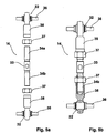
- FIGS 5a and 5b show the coupling element 14 in an exploded view and in an assembled representation, and the coupling element 14 has coupling joints 32 at the ends, via which the coupling element 14 to the fastening bodies 12 and 13 according to Figure 1 can be articulated.
- the coupling joints 32 are designed with hinge pins 36 and form ball joints, and the hinge pins 36 can be firmly connected, in particular screwed, to the coupling parts 16 of the fastening bodies 12, 13.
- the coupling elements 14 have a threaded rod 33, and the threaded rod 33 has a first threaded region 34a and a second threaded region 34b.
- End elements 35 are screwed onto the threaded areas 34a, 34b, with the threaded areas 34a and 34b particularly advantageously forming a right-hand thread and a left-hand thread. If the end elements 35 are fixed, both threaded regions 34a, 34b can be inserted into the end elements 35 by rotating the threaded rod 33 in one direction of rotation be screwed in.
- Locking nuts 37 are used to fix the screw-in depth.
- the distance between the hinge pins 36 can also be set in the fully assembled state of the stabilizer device 1 between the car bodies 10, 11, so that only the lock nuts 37 with the end elements 35 on the to secure the set length of the coupling element 14 Thread areas 34a, 34b must be braced.
- the exemplary embodiment of a stabilizer device 1 listed results in a simple, inexpensive and robust design in order to dampen and / or reduce roll movements between the car bodies 10, 11 of a rail vehicle or, for example, also of a road vehicle, in particular a bus.
- the swivel joint 17 can be made very robust and has no fluid damper, via which the damping effect must be achieved.
- the damping means 18 is formed by the robust elastic body 19, which has a sufficient energy-dissipating effect when deformed, so that vibrations between the car bodies 10, 11 can preferably be damped or canceled out by the stabilizer device 1.
- the embodiment of the invention is not limited to the preferred exemplary embodiment specified above. Rather, a number of variants are conceivable which make use of the solution shown even in the case of fundamentally different types. All features and / or advantages arising from the claims, the description or the drawings, including constructive Details or spatial arrangements can be essential to the invention both individually and in a wide variety of combinations.
- the flange parts 15 can also be formed in one piece with or as a molded part on the end faces of the car bodies 10, 11, in or on which the rotary joints 17 are received.
Landscapes
- Engineering & Computer Science (AREA)
- General Engineering & Computer Science (AREA)
- Mechanical Engineering (AREA)
- Health & Medical Sciences (AREA)
- Child & Adolescent Psychology (AREA)
- Vehicle Body Suspensions (AREA)
- Pivots And Pivotal Connections (AREA)
Applications Claiming Priority (1)
| Application Number | Priority Date | Filing Date | Title |
|---|---|---|---|
| DE202018105298.5U DE202018105298U1 (de) | 2018-09-17 | 2018-09-17 | Stabilisatorvorrichtung für Schienenfahrzeuge, insbesondere Wankstabilisatoren |
Publications (3)
| Publication Number | Publication Date |
|---|---|
| EP3623251A1 true EP3623251A1 (fr) | 2020-03-18 |
| EP3623251C0 EP3623251C0 (fr) | 2023-09-27 |
| EP3623251B1 EP3623251B1 (fr) | 2023-09-27 |
Family
ID=64745319
Family Applications (1)
| Application Number | Title | Priority Date | Filing Date |
|---|---|---|---|
| EP19193998.2A Active EP3623251B1 (fr) | 2018-09-17 | 2019-08-28 | Dispositif stabilisateur pour véhicules ferroviaires, en particulier stabilisateur de roulis |
Country Status (4)
| Country | Link |
|---|---|
| EP (1) | EP3623251B1 (fr) |
| CN (1) | CN110901680B (fr) |
| DE (1) | DE202018105298U1 (fr) |
| ES (1) | ES2963302T3 (fr) |
Families Citing this family (2)
| Publication number | Priority date | Publication date | Assignee | Title |
|---|---|---|---|---|
| DE102019109611A1 (de) * | 2019-04-11 | 2020-10-15 | Bombardier Transportation Gmbh | Gelenkvorrichtung für ein gelenkfahrzeug und gelenkfahrzeug |
| CN110435705B (zh) * | 2019-08-14 | 2020-12-01 | 株洲中车特种装备科技有限公司 | 一种单轴游览列车铰接系统 |
Citations (4)
| Publication number | Priority date | Publication date | Assignee | Title |
|---|---|---|---|---|
| US1740357A (en) * | 1928-07-24 | 1929-12-17 | Gen Electric | Restraining device |
| NL39938C (nl) * | 1934-05-09 | 1937-01-15 | Inrichting voor het dempen van de slingerende bewegingen van zich over rails bewegende voertuigen | |
| DE693928C (de) * | 1938-03-23 | 1940-07-22 | Christoph & Unmack Akt Ges | Vorrichtung zur Verbesserung der Standfestigkeit dnachsigen Wagen |
| EP2765050A1 (fr) | 2013-02-09 | 2014-08-13 | Hübner GmbH & Co. KG | Dispositif agencé dans la zone de toit de deux éléments de véhicule reliés de manière articulée, destiné à la limitation du mouvement de tangage des éléments de véhicule les uns par rapport aux autres |
Family Cites Families (12)
| Publication number | Priority date | Publication date | Assignee | Title |
|---|---|---|---|---|
| GB247788A (en) * | 1925-04-04 | 1926-02-25 | Walter Carman White | Improvements in and relating to train pipe couplings |
| DD122174A3 (fr) * | 1974-11-11 | 1976-09-20 | ||
| DE4201122A1 (de) * | 1992-01-17 | 1993-07-22 | Duewag Ag | Wageneinheit, insbesondere fuer den guetertransport |
| CN2189574Y (zh) * | 1994-03-08 | 1995-02-15 | 于修贵 | 矿车用组合式刚性连杆 |
| CN201296258Y (zh) * | 2008-07-29 | 2009-08-26 | 溧阳市振大铁路设备有限公司 | 动车组车辆用抗侧滚扭杆装置 |
| CN101612943A (zh) * | 2009-06-30 | 2009-12-30 | 中国北车集团大连机车研究所有限公司 | 城市低地板轨道车辆多节连挂铰接机构 |
| CN201538329U (zh) * | 2009-06-30 | 2010-08-04 | 中国北车集团大连机车研究所有限公司 | 城市低地板轨道车辆铰接用自由铰接装置 |
| CN201721457U (zh) * | 2010-07-14 | 2011-01-26 | 青岛华轩交通装备科技有限公司 | 一种轻轨牵引万向控制铰机构 |
| DE102014010803A1 (de) * | 2014-07-22 | 2016-01-28 | Man Truck & Bus Ag | Fahrzeuggelenk für ein Gelenkfahrzeug mit Dämpfungseinrichtung |
| CN203995516U (zh) * | 2014-08-18 | 2014-12-10 | 东风汽车公司 | 一种长度可调的硬牵引装置 |
| CN205601858U (zh) * | 2016-05-19 | 2016-09-28 | 虎伯拉铰接系统(上海)有限公司 | 有轨车辆及其自由铰系统 |
| CN107458413A (zh) * | 2016-06-02 | 2017-12-12 | 株洲时代新材料科技股份有限公司 | 一种低地板车车体之间自由铰接连接方法及铰接系统 |
-
2018
- 2018-09-17 DE DE202018105298.5U patent/DE202018105298U1/de active Active
-
2019
- 2019-08-28 EP EP19193998.2A patent/EP3623251B1/fr active Active
- 2019-08-28 ES ES19193998T patent/ES2963302T3/es active Active
- 2019-09-16 CN CN201910870220.2A patent/CN110901680B/zh active Active
Patent Citations (4)
| Publication number | Priority date | Publication date | Assignee | Title |
|---|---|---|---|---|
| US1740357A (en) * | 1928-07-24 | 1929-12-17 | Gen Electric | Restraining device |
| NL39938C (nl) * | 1934-05-09 | 1937-01-15 | Inrichting voor het dempen van de slingerende bewegingen van zich over rails bewegende voertuigen | |
| DE693928C (de) * | 1938-03-23 | 1940-07-22 | Christoph & Unmack Akt Ges | Vorrichtung zur Verbesserung der Standfestigkeit dnachsigen Wagen |
| EP2765050A1 (fr) | 2013-02-09 | 2014-08-13 | Hübner GmbH & Co. KG | Dispositif agencé dans la zone de toit de deux éléments de véhicule reliés de manière articulée, destiné à la limitation du mouvement de tangage des éléments de véhicule les uns par rapport aux autres |
Also Published As
| Publication number | Publication date |
|---|---|
| EP3623251C0 (fr) | 2023-09-27 |
| DE202018105298U1 (de) | 2018-12-07 |
| ES2963302T3 (es) | 2024-03-26 |
| CN110901680B (zh) | 2021-11-02 |
| EP3623251B1 (fr) | 2023-09-27 |
| CN110901680A (zh) | 2020-03-24 |
Similar Documents
| Publication | Publication Date | Title |
|---|---|---|
| EP2243680B1 (fr) | Articulation destinée à la liaison articulée d'une tige d'embrayage et d'une caisse de voiture | |
| DE102010048210B4 (de) | Fahrzeugsitz mit Fluidfeder | |
| EP3042098B1 (fr) | Élément de retenue d'un ressort | |
| EP2391517B1 (fr) | Disposition d'un bras oscillant transversal avec un coussinet d'une suspension de véhicule automobile | |
| DE102010021481B3 (de) | Fahrzeugsitz | |
| EP2414180B1 (fr) | Articulation elastomere | |
| EP2736732B1 (fr) | Dispositif d'ajustement des essieux de véhicules utilitaires | |
| DE3346665A1 (de) | Elastisches lager mit zwangsfuehrung | |
| DE19805810A1 (de) | Verbindungselement für einen Torsionsstabilisator | |
| DE1780082A1 (de) | Aufhaengung fuer Kraftfahrzeuge | |
| DE3629068C2 (fr) | ||
| DE2215330A1 (de) | Elastisches gelenk, insbesondere fuer lenkgestaenge von kraftfahrzeugen | |
| EP3623251B1 (fr) | Dispositif stabilisateur pour véhicules ferroviaires, en particulier stabilisateur de roulis | |
| WO2017121558A1 (fr) | Bras de suspension articulé en deux points à longueur réglable, en particulier pour une direction ou un train roulant d'un véhicule utilitaire | |
| DE20009859U1 (de) | Vorrichtung zur elastischen Lagerung des Kupplungsarmes einer Mittelpufferkupplung an einem Schienenfahrzeug | |
| EP4119368A1 (fr) | Appareil d'appui à rotule pour l'appui d'un bras de commande de véhicule | |
| DE19748117C2 (de) | Kugelzapfen | |
| DE102011052747A1 (de) | Spannelement für eine Spannvorrichtung | |
| EP1956252B1 (fr) | Unité de déplacement longitudinal pour arbres de transmission | |
| DE10050773B4 (de) | Achsaufhängung | |
| DE3138534A1 (de) | Vorrichtung zur elastischen aufhaengung einer strebe,stuetze o.ae. | |
| DE102019131736B3 (de) | Lagerauge für eine Blattfeder sowie Blattfeder mit einem Lagerauge | |
| DE202011051001U1 (de) | Spannelement für eine Spannvorrichtung | |
| DE102017214235B3 (de) | Kopplungsvorrichtung | |
| EP3554918B1 (fr) | Articulation pour la liaison articulée d'une barre d'attelage à une caisse de wagon |
Legal Events
| Date | Code | Title | Description |
|---|---|---|---|
| PUAI | Public reference made under article 153(3) epc to a published international application that has entered the european phase |
Free format text: ORIGINAL CODE: 0009012 |
|
| STAA | Information on the status of an ep patent application or granted ep patent |
Free format text: STATUS: THE APPLICATION HAS BEEN PUBLISHED |
|
| AK | Designated contracting states |
Kind code of ref document: A1 Designated state(s): AL AT BE BG CH CY CZ DE DK EE ES FI FR GB GR HR HU IE IS IT LI LT LU LV MC MK MT NL NO PL PT RO RS SE SI SK SM TR |
|
| AX | Request for extension of the european patent |
Extension state: BA ME |
|
| STAA | Information on the status of an ep patent application or granted ep patent |
Free format text: STATUS: REQUEST FOR EXAMINATION WAS MADE |
|
| 17P | Request for examination filed |
Effective date: 20201102 |
|
| RBV | Designated contracting states (corrected) |
Designated state(s): AL AT BE BG CH CY CZ DE DK EE ES FI FR GB GR HR HU IE IS IT LI LT LU LV MC MK MT NL NO PL PT RO RS SE SI SK SM TR |
|
| STAA | Information on the status of an ep patent application or granted ep patent |
Free format text: STATUS: EXAMINATION IS IN PROGRESS |
|
| 17Q | First examination report despatched |
Effective date: 20220218 |
|
| GRAP | Despatch of communication of intention to grant a patent |
Free format text: ORIGINAL CODE: EPIDOSNIGR1 |
|
| STAA | Information on the status of an ep patent application or granted ep patent |
Free format text: STATUS: GRANT OF PATENT IS INTENDED |
|
| INTG | Intention to grant announced |
Effective date: 20230330 |
|
| GRAS | Grant fee paid |
Free format text: ORIGINAL CODE: EPIDOSNIGR3 |
|
| GRAA | (expected) grant |
Free format text: ORIGINAL CODE: 0009210 |
|
| STAA | Information on the status of an ep patent application or granted ep patent |
Free format text: STATUS: THE PATENT HAS BEEN GRANTED |
|
| AK | Designated contracting states |
Kind code of ref document: B1 Designated state(s): AL AT BE BG CH CY CZ DE DK EE ES FI FR GB GR HR HU IE IS IT LI LT LU LV MC MK MT NL NO PL PT RO RS SE SI SK SM TR |
|
| REG | Reference to a national code |
Ref country code: GB Ref legal event code: FG4D Free format text: NOT ENGLISH |
|
| REG | Reference to a national code |
Ref country code: CH Ref legal event code: EP |
|
| P01 | Opt-out of the competence of the unified patent court (upc) registered |
Effective date: 20230911 |
|
| REG | Reference to a national code |
Ref country code: DE Ref legal event code: R096 Ref document number: 502019009476 Country of ref document: DE |
|
| REG | Reference to a national code |
Ref country code: IE Ref legal event code: FG4D Free format text: LANGUAGE OF EP DOCUMENT: GERMAN |
|
| U01 | Request for unitary effect filed |
Effective date: 20231011 |
|
| P04 | Withdrawal of opt-out of the competence of the unified patent court (upc) registered |
Effective date: 20231016 |
|
| U07 | Unitary effect registered |
Designated state(s): AT BE BG DE DK EE FI FR IT LT LU LV MT NL PT SE SI Effective date: 20231019 |
|
| PG25 | Lapsed in a contracting state [announced via postgrant information from national office to epo] |
Ref country code: GR Free format text: LAPSE BECAUSE OF FAILURE TO SUBMIT A TRANSLATION OF THE DESCRIPTION OR TO PAY THE FEE WITHIN THE PRESCRIBED TIME-LIMIT Effective date: 20231228 |
|
| PG25 | Lapsed in a contracting state [announced via postgrant information from national office to epo] |
Ref country code: RS Free format text: LAPSE BECAUSE OF FAILURE TO SUBMIT A TRANSLATION OF THE DESCRIPTION OR TO PAY THE FEE WITHIN THE PRESCRIBED TIME-LIMIT Effective date: 20230927 Ref country code: NO Free format text: LAPSE BECAUSE OF FAILURE TO SUBMIT A TRANSLATION OF THE DESCRIPTION OR TO PAY THE FEE WITHIN THE PRESCRIBED TIME-LIMIT Effective date: 20231227 Ref country code: HR Free format text: LAPSE BECAUSE OF FAILURE TO SUBMIT A TRANSLATION OF THE DESCRIPTION OR TO PAY THE FEE WITHIN THE PRESCRIBED TIME-LIMIT Effective date: 20230927 Ref country code: GR Free format text: LAPSE BECAUSE OF FAILURE TO SUBMIT A TRANSLATION OF THE DESCRIPTION OR TO PAY THE FEE WITHIN THE PRESCRIBED TIME-LIMIT Effective date: 20231228 |
|
| REG | Reference to a national code |
Ref country code: ES Ref legal event code: FG2A Ref document number: 2963302 Country of ref document: ES Kind code of ref document: T3 Effective date: 20240326 |
|
| PG25 | Lapsed in a contracting state [announced via postgrant information from national office to epo] |
Ref country code: IS Free format text: LAPSE BECAUSE OF FAILURE TO SUBMIT A TRANSLATION OF THE DESCRIPTION OR TO PAY THE FEE WITHIN THE PRESCRIBED TIME-LIMIT Effective date: 20240127 |
|
| PG25 | Lapsed in a contracting state [announced via postgrant information from national office to epo] |
Ref country code: SM Free format text: LAPSE BECAUSE OF FAILURE TO SUBMIT A TRANSLATION OF THE DESCRIPTION OR TO PAY THE FEE WITHIN THE PRESCRIBED TIME-LIMIT Effective date: 20230927 Ref country code: RO Free format text: LAPSE BECAUSE OF FAILURE TO SUBMIT A TRANSLATION OF THE DESCRIPTION OR TO PAY THE FEE WITHIN THE PRESCRIBED TIME-LIMIT Effective date: 20230927 Ref country code: IS Free format text: LAPSE BECAUSE OF FAILURE TO SUBMIT A TRANSLATION OF THE DESCRIPTION OR TO PAY THE FEE WITHIN THE PRESCRIBED TIME-LIMIT Effective date: 20240127 Ref country code: CZ Free format text: LAPSE BECAUSE OF FAILURE TO SUBMIT A TRANSLATION OF THE DESCRIPTION OR TO PAY THE FEE WITHIN THE PRESCRIBED TIME-LIMIT Effective date: 20230927 Ref country code: SK Free format text: LAPSE BECAUSE OF FAILURE TO SUBMIT A TRANSLATION OF THE DESCRIPTION OR TO PAY THE FEE WITHIN THE PRESCRIBED TIME-LIMIT Effective date: 20230927 |
|
| PG25 | Lapsed in a contracting state [announced via postgrant information from national office to epo] |
Ref country code: PL Free format text: LAPSE BECAUSE OF FAILURE TO SUBMIT A TRANSLATION OF THE DESCRIPTION OR TO PAY THE FEE WITHIN THE PRESCRIBED TIME-LIMIT Effective date: 20230927 |
|
| REG | Reference to a national code |
Ref country code: DE Ref legal event code: R097 Ref document number: 502019009476 Country of ref document: DE |
|
| PLBE | No opposition filed within time limit |
Free format text: ORIGINAL CODE: 0009261 |
|
| STAA | Information on the status of an ep patent application or granted ep patent |
Free format text: STATUS: NO OPPOSITION FILED WITHIN TIME LIMIT |
|
| 26N | No opposition filed |
Effective date: 20240628 |
|
| U20 | Renewal fee for the european patent with unitary effect paid |
Year of fee payment: 6 Effective date: 20240814 |
|
| P05 | Withdrawal of opt-out of the competence of the unified patent court (upc) changed |
Free format text: CASE NUMBER: APP_580611/2023 Effective date: 20231019 |
|
| REG | Reference to a national code |
Ref country code: CH Ref legal event code: PL |
|
| GBPC | Gb: european patent ceased through non-payment of renewal fee |
Effective date: 20240828 |
|
| PG25 | Lapsed in a contracting state [announced via postgrant information from national office to epo] |
Ref country code: MC Free format text: LAPSE BECAUSE OF FAILURE TO SUBMIT A TRANSLATION OF THE DESCRIPTION OR TO PAY THE FEE WITHIN THE PRESCRIBED TIME-LIMIT Effective date: 20230927 Ref country code: CH Free format text: LAPSE BECAUSE OF NON-PAYMENT OF DUE FEES Effective date: 20240831 |
|
| PG25 | Lapsed in a contracting state [announced via postgrant information from national office to epo] |
Ref country code: GB Free format text: LAPSE BECAUSE OF NON-PAYMENT OF DUE FEES Effective date: 20240828 |
|
| PG25 | Lapsed in a contracting state [announced via postgrant information from national office to epo] |
Ref country code: IE Free format text: LAPSE BECAUSE OF NON-PAYMENT OF DUE FEES Effective date: 20240828 |
|
| U20 | Renewal fee for the european patent with unitary effect paid |
Year of fee payment: 7 Effective date: 20250826 |
|
| PGFP | Annual fee paid to national office [announced via postgrant information from national office to epo] |
Ref country code: ES Payment date: 20250917 Year of fee payment: 7 |
|
| PG25 | Lapsed in a contracting state [announced via postgrant information from national office to epo] |
Ref country code: CY Free format text: LAPSE BECAUSE OF FAILURE TO SUBMIT A TRANSLATION OF THE DESCRIPTION OR TO PAY THE FEE WITHIN THE PRESCRIBED TIME-LIMIT; INVALID AB INITIO Effective date: 20190828 |
|
| PG25 | Lapsed in a contracting state [announced via postgrant information from national office to epo] |
Ref country code: HU Free format text: LAPSE BECAUSE OF FAILURE TO SUBMIT A TRANSLATION OF THE DESCRIPTION OR TO PAY THE FEE WITHIN THE PRESCRIBED TIME-LIMIT; INVALID AB INITIO Effective date: 20190828 |