EP3623280A1 - Aerodynamische flugzeugkomponente - Google Patents
Aerodynamische flugzeugkomponente Download PDFInfo
- Publication number
- EP3623280A1 EP3623280A1 EP19196669.6A EP19196669A EP3623280A1 EP 3623280 A1 EP3623280 A1 EP 3623280A1 EP 19196669 A EP19196669 A EP 19196669A EP 3623280 A1 EP3623280 A1 EP 3623280A1
- Authority
- EP
- European Patent Office
- Prior art keywords
- aerodynamic part
- slat
- aircraft component
- piece
- magnet device
- Prior art date
- Legal status (The legal status is an assumption and is not a legal conclusion. Google has not performed a legal analysis and makes no representation as to the accuracy of the status listed.)
- Withdrawn
Links
- 239000000696 magnetic material Substances 0.000 claims abstract description 32
- 238000000034 method Methods 0.000 abstract description 6
- 239000000463 material Substances 0.000 description 3
- 239000003381 stabilizer Substances 0.000 description 2
- 230000008878 coupling Effects 0.000 description 1
- 238000010168 coupling process Methods 0.000 description 1
- 238000005859 coupling reaction Methods 0.000 description 1
Images


Classifications
-
- B—PERFORMING OPERATIONS; TRANSPORTING
- B64—AIRCRAFT; AVIATION; COSMONAUTICS
- B64C—AEROPLANES; HELICOPTERS
- B64C9/00—Adjustable control surfaces or members, e.g. rudders
- B64C9/02—Mounting or supporting thereof
-
- B—PERFORMING OPERATIONS; TRANSPORTING
- B64—AIRCRAFT; AVIATION; COSMONAUTICS
- B64C—AEROPLANES; HELICOPTERS
- B64C9/00—Adjustable control surfaces or members, e.g. rudders
- B64C9/14—Adjustable control surfaces or members, e.g. rudders forming slots
- B64C9/22—Adjustable control surfaces or members, e.g. rudders forming slots at the front of the wing
- B64C9/24—Adjustable control surfaces or members, e.g. rudders forming slots at the front of the wing by single flap
-
- B—PERFORMING OPERATIONS; TRANSPORTING
- B64—AIRCRAFT; AVIATION; COSMONAUTICS
- B64C—AEROPLANES; HELICOPTERS
- B64C9/00—Adjustable control surfaces or members, e.g. rudders
- B64C9/14—Adjustable control surfaces or members, e.g. rudders forming slots
-
- B—PERFORMING OPERATIONS; TRANSPORTING
- B64—AIRCRAFT; AVIATION; COSMONAUTICS
- B64C—AEROPLANES; HELICOPTERS
- B64C5/00—Stabilising surfaces
- B64C5/02—Tailplanes
-
- B—PERFORMING OPERATIONS; TRANSPORTING
- B64—AIRCRAFT; AVIATION; COSMONAUTICS
- B64C—AEROPLANES; HELICOPTERS
- B64C5/00—Stabilising surfaces
- B64C5/10—Stabilising surfaces adjustable
Definitions
- the present invention relates to an aerodynamic aircraft component, such as a wing or a tail unit of an aircraft.
- a further aspect of the present invention relates to an aircraft comprising such an aircraft component.
- the aerodynamic aircraft component comprises a fixed aerodynamic part and a movable aerodynamic part.
- the fixed aerodynamic part and the movable aerodynamic part relate to parts that have an aerodynamic function for the aircraft and/or that have an aerodynamic surface that is in contact with the ambient flow.
- the fixed aerodynamic part has a first contact surface and the movable aerodynamic part has a second contact surface.
- the movable aerodynamic part is mounted to the fixed aerodynamic part such that it is movable relative to the fixed aerodynamic part between a first position where the first and second contact surfaces are spaced from one another, and a second position where the second contact surface contacts the first contact surface.
- Such an aerodynamic aircraft component might be, for example, a wing wherein the fixed aerodynamic part is a fixed wing, the movable aerodynamic part is a slat, the first position corresponds to an extended position of the slat, the second position corresponds to a retracted position of the slat, the first contact surface is arranged at a leading edge of the fixed wing, and the second contact surface is arranged at a trailing edge of the slat.
- Such wings are known in the art. Rigging of the slat with respect to the fixed wing might be a complicated and time consuming procedure at the known wings.
- the angular position of the slat with respect to the fixed wing is adjusted with the aid of an eccentric bolt at a side link coupling a mount of the slat to a slat track.
- By angular adjustment of the eccentric bolt the angular orientation of the slat about a span direction is adjusted until the trailing edge of the slat presses against the leading edge of the fixed wing with a predefined pressure.
- This manual rigging process is very laborious.
- the object of the present invention is to provide an aerodynamic aircraft component that allows a simplified rigging process.
- the fixed aerodynamic part comprises, preferably in the area of the first contact surface, one of a magnet device and a piece of magnetic material.
- the movable aerodynamic part comprises, preferably in the area of the second contact surface, the other of the magnet device and the piece of magnetic material.
- the magnet device and the piece of magnetic material are arranged such that a magnetic force between the magnet device and the piece of magnetic material urges, preferably presses with defined pressure, the second contact surface to the second position and in defined, predetermined contact with the first contact surface.
- the manual rigging can be replaced or at least assisted by the magnetic force between the magnet device and the piece of magnetic material to press the first and second contact surfaces together.
- the aerodynamic aircraft component is a wing, a vertical tail plane, or a horizontal tail plane. These are common aerodynamic aircraft components.
- the movable aerodynamic part is a control surface, such as an aileron, a spoiler, a rudder, or an elevator.
- the fixed aerodynamic part might be a fixed wing while the movable aerodynamic part might be a control surface in the form of an aileron or a spoiler.
- the aerodynamic aircraft component is a vertical tail plane (VTP)
- the fixed aerodynamic part might be a vertical stabilizer while the movable aerodynamic part might be a control surface in the form of a rudder.
- the aerodynamic aircraft component is a horizontal tail plane (HTP)
- the fixed aerodynamic part might be a horizontal stabilizer while the movable aerodynamic part might be a control surface in the form of an elevator.
- the movable aerodynamic part is a high lift surface.
- the fixed aerodynamic part might be a fixed wing while the movable aerodynamic part might be a high lift surface in the form of a flap or a slat.
- the manual rigging process is extensive and desirable to be replaced by magnetic rigging.
- the aerodynamic aircraft component is a wing
- the fixed aerodynamic part is a fixed wing
- the movable aerodynamic part is a slat
- the first position corresponds to an extended position of the slat
- the second position corresponds to a retracted position of the slat
- the first contact surface is arranged at a leading edge of the fixed wing
- the second contact surface is arranged at a trailing edge of the slat.
- slats rigging is done such that the trailing edge of the slat is pressed against the leading edge of the fixed wing, which makes the manual rigging process extensive and desirable to be replaced by magnetic rigging.
- the magnet device is arranged at the leading edge of the fixed wing and the piece of magnetic material is arranged at the trailing edge of the slat.
- Such an arrangement is advantageous considering the spatial constraints at the trailing edge of the slat.
- the magnet device is arranged at the trailing edge of the slat and the piece of magnetic material is arranged at the leading edge of the fixed wing.
- the slat further comprises a main body comprising a leading edge of the slat.
- a resilient area is provided between the trailing edge of the slat and the main body of the slat , so that the trailing edge of the slat due to the magnetic force may deform with respect to the main body by pivoting about the resilient area when the trailing edge is urged in contact with the leading edge of the fixed wing to establish contact between the first and second contact surfaces.
- the resilient area might be formed e.g. by a material with reduced stiffness and/or by a neck of material and/or by a spring.
- the magnet device and/or the piece of magnetic material extend continuously along the span extension of the movable aerodynamic part, preferably along the entire or at least along the essential span extension of the movable aerodynamic part.
- a continuous and reliable magnetic force can be applied between the fixed and movable aerodynamic parts along the span extension of the movable aerodynamic part.
- resilient area i.e. the resilient area might extend continuously along the span extension of the movable aerodynamic part.
- the magnet device and/or the piece of magnetic material extend in an interrupted manner along the span extension of the movable aerodynamic part. I.e., the magnet device and/or the piece of magnetic material are provided only at discrete positions along the span extension of the movable aerodynamic part. In such a way, weight can be saved.
- the magnet device is a permanent magnet or an electromagnet.
- an electromagnet is that it might be switched on and off, and can thus be applied only when needed.
- the magnet device and the piece of magnetic material are adapted such that the magnetic force is strong enough to inhibit air from passing between the fixed aerodynamic part and the movable aerodynamic part when the first and second contact surfaces are in contact.
- This is particularly advantageous for the slat where the trailing edge of the slat is ideally pressed against the leading edge of the fixed wing so that air is inhibited from passing therebetween, for aerodynamic reasons.
- the magnet device and/or the piece of magnetic material have such a chord extension that the first and second contact surfaces remain in contact along a defined path when the movable aerodynamic part is moved out of the second position relative to the fixed aerodynamic part.
- air is inhibited from passing between the trailing edge of the slat and the leading edge of the fixed wing even when the slat is moved from the second position in the direction of the first position, for the length of the defined path.
- a further aspect of the present invention relates to an aircraft comprising the aircraft component according to any of the embodiments described above.
- the features and advantageous described in connection with the aircraft component apply vis-à-vis to the aircraft.
- FIG. 1 an aircraft 1 according to an embodiment of the present invention is shown.
- the aircraft 1 comprises a fuselage 3 and several aerodynamic aircraft components 4 according to an embodiment of the invention.
- the aerodynamic aircraft components 4 are in the form of wings 5, a horizontal tail plane 7, and a vertical tail plane 9.
- a wing 5, 5' is described in more detail in connection with Figs. 2 and 3 .
- the aerodynamic aircraft component 4, 4' in the form of the wing 5, 5' comprises a fixed aerodynamic part 11, 11' in the form of a fixed wing 13, 13' and a movable aerodynamic part 15, 15' in the form a slat 17, 17'.
- the fixed wing 13, 13' has a first contact surface 19, 19' and the slat 17, 17' has a second contact surface 21, 21'.
- the slat 17, 17' is mounted to the fixed wing 13, 13' such that it is movable relative to the fixed wing 13, 13' between an extended position where the first and second contact surfaces 19, 19', 21, 21' are spaced from one another, and a retracted position where the second contact surface 21, 21' contacts the first contact surface 19, 19'.
- Fig. 2 shows a prior art wing 5', wherein rigging of the slat 17' is done manually. Specifically, the angular position of the slat 17' with respect to the fixed wing 13' is adjusted with the aid of an eccentric bolt 23' at a side link 25' that couples a mount 27' of the slat 17' to a slat track 29' that is movable supported at the fixed wing 13'.
- the eccentric bolt 23' By angular adjusting the eccentric bolt 23' the angular orientation of the slat 17' about a span direction 31' is adjusted until a trailing edge 33' of the slat 17' presses against the leading edge 35' of the fixed wing 13' with a predefined pressure.
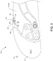
- Fig. 3 shows a wing 5 according to the present invention, wherein rigging of the slat 17 is done magnetically.
- the fixed wing 13 comprises in the area of the first contact surface 19 a magnet device 37.
- the slat 17 comprises in the area of the second contact surface 21 a piece 39 of magnetic material.
- the magnet device 37 and the piece 39 of magnetic material are arranged such that a magnetic force 40 between the magnet device 37 and the piece 39 of magnetic material urges the second contact surface 21 in defined contact with the first contact surface 19.
- the magnet device 37 is arranged at the leading edge 35 of the fixed wing 13 and the piece 39 of magnetic material is arranged at the trailing edge 33 of the slat 17.
- the slat 17 further comprises a main body 41, wherein between the trailing edge 33 of the slat 17 and the main body 41 of the slat 17 a resilient area 43 is provided, so that the trailing edge 33 of the slat 17 due to the magnetic force may deform with respect to the main body 41 by pivoting about the resilient area 43 when the trailing edge 33 is urged in contact with the leading edge 35 of the fixed wing 13 to establish contact between the first and second contact surfaces 19, 21.
- the resilient area 43 is formed by a neck of material.
- the magnet device 37, the piece 39 of magnetic material and the resilient area 43 extend continuously along the span direction 31 extension of the slat 17.
- the magnet device 37 and the piece 39 of magnetic material are adapted such that the magnetic force 40 is strong enough to inhibit air from passing between the leading edge 35 of the fixed wing 13 and the trailing edge 33 of the slat 17 when the first and second contact surfaces 19, 21 are in contact.
- the magnet device 37 and the piece 39 of magnetic material have such an extension in a chord direction 45 that the first and second contact surfaces 19, 21 remain in contact along a defined path when the movable aerodynamic part 15 is moved out of the second position relative to the fixed aerodynamic part 11.
Landscapes
- Engineering & Computer Science (AREA)
- Aviation & Aerospace Engineering (AREA)
- Aerodynamic Tests, Hydrodynamic Tests, Wind Tunnels, And Water Tanks (AREA)
- Toys (AREA)
- Details Of Aerials (AREA)
Applications Claiming Priority (1)
| Application Number | Priority Date | Filing Date | Title |
|---|---|---|---|
| DE102018122208 | 2018-09-12 |
Publications (1)
| Publication Number | Publication Date |
|---|---|
| EP3623280A1 true EP3623280A1 (de) | 2020-03-18 |
Family
ID=67928687
Family Applications (1)
| Application Number | Title | Priority Date | Filing Date |
|---|---|---|---|
| EP19196669.6A Withdrawn EP3623280A1 (de) | 2018-09-12 | 2019-09-11 | Aerodynamische flugzeugkomponente |
Country Status (3)
| Country | Link |
|---|---|
| US (1) | US11401028B2 (de) |
| EP (1) | EP3623280A1 (de) |
| CN (1) | CN110893906B (de) |
Families Citing this family (2)
| Publication number | Priority date | Publication date | Assignee | Title |
|---|---|---|---|---|
| CN112896489B (zh) * | 2021-02-19 | 2021-08-31 | 西北工业大学 | 一种开缝导流片式增升装置 |
| US11926416B1 (en) * | 2022-08-18 | 2024-03-12 | The Boeing Company | Flight control systems and related methods of magnetically counteracting aerodynamic lift forces on flight control surfaces |
Citations (5)
| Publication number | Priority date | Publication date | Assignee | Title |
|---|---|---|---|---|
| US6981676B2 (en) * | 2003-09-22 | 2006-01-03 | Airbus France | Method and spoiler system for ensuring the aerodynamic continuity of the upper surface of an aircraft |
| US9242718B2 (en) * | 2010-11-09 | 2016-01-26 | Airbus Operations Limited | Seal assembly |
| US20160229526A1 (en) * | 2015-02-06 | 2016-08-11 | Airbus Operations Gmbh | Vortex generator arrangement |
| US10017239B2 (en) * | 2015-12-18 | 2018-07-10 | Northrop Grumman Systems Corporation | Dynamic conformal aerodynamic seal (CAS) for aircraft control surfaces |
| EP3395677A1 (de) * | 2017-04-26 | 2018-10-31 | Airbus Operations Limited | Magnetische abdichtungen |
Family Cites Families (11)
| Publication number | Priority date | Publication date | Assignee | Title |
|---|---|---|---|---|
| US3109613A (en) * | 1960-11-28 | 1963-11-05 | Mabel Wilson Raspet | Variable-camber airfoil |
| DE10157849A1 (de) * | 2001-11-24 | 2003-06-12 | Airbus Gmbh | Anordnung zur Minderung des aerodynamischen Lärms an einem Vorflügel eines Verkehrsflugzeuges |
| JP4699487B2 (ja) * | 2007-05-25 | 2011-06-08 | 三菱重工業株式会社 | 高揚力発生装置、翼および高揚力発生装置の騒音低減構造 |
| GB0911012D0 (en) * | 2009-06-25 | 2009-08-12 | Airbus Operations Ltd | Cross-bleed dam |
| US8864083B1 (en) * | 2010-03-31 | 2014-10-21 | The Boeing Company | Low noise wing slat system with a fixed wing leading edge and deployable bridging panels |
| US9242720B2 (en) * | 2010-10-21 | 2016-01-26 | The United States Of America As Represented By The Administrator Of The National Aeronautics And Space Administration | Autonomous slat-cove-filler device for reduction of aeroacoustic noise associated with aircraft systems |
| US9010693B1 (en) | 2011-05-03 | 2015-04-21 | James Emmett Dee Barbieri | Collapsible wing and unmanned aircraft system including collapsible wing |
| US9457887B2 (en) | 2014-03-05 | 2016-10-04 | Toyota Motor Engineering & Manufacturing North America, Inc. | Smart material trailing edge variable chord morphing wing |
| DE202015000665U1 (de) * | 2015-01-24 | 2015-06-26 | Dieter Röhm | Vorrichtung eines Sicherheitssystems und/oder Ressourcen-/Energieeffizienz-Verbesserungs - Systems zur Stömungsbeeinflussung eines Aero- oder Hydrodynamischen Körpers (3), nach dem Prinzip einer Rückstromklappe (4) |
| GB2540953A (en) * | 2015-07-31 | 2017-02-08 | Airbus Operations Ltd | A control surface for an aircraft |
| US9809295B1 (en) * | 2016-06-07 | 2017-11-07 | Northrop Grumman Systems Corporation | Flight actuated door seal |
-
2019
- 2019-09-10 CN CN201910852647.XA patent/CN110893906B/zh active Active
- 2019-09-11 EP EP19196669.6A patent/EP3623280A1/de not_active Withdrawn
- 2019-09-11 US US16/567,609 patent/US11401028B2/en active Active
Patent Citations (5)
| Publication number | Priority date | Publication date | Assignee | Title |
|---|---|---|---|---|
| US6981676B2 (en) * | 2003-09-22 | 2006-01-03 | Airbus France | Method and spoiler system for ensuring the aerodynamic continuity of the upper surface of an aircraft |
| US9242718B2 (en) * | 2010-11-09 | 2016-01-26 | Airbus Operations Limited | Seal assembly |
| US20160229526A1 (en) * | 2015-02-06 | 2016-08-11 | Airbus Operations Gmbh | Vortex generator arrangement |
| US10017239B2 (en) * | 2015-12-18 | 2018-07-10 | Northrop Grumman Systems Corporation | Dynamic conformal aerodynamic seal (CAS) for aircraft control surfaces |
| EP3395677A1 (de) * | 2017-04-26 | 2018-10-31 | Airbus Operations Limited | Magnetische abdichtungen |
Also Published As
| Publication number | Publication date |
|---|---|
| CN110893906B (zh) | 2023-08-25 |
| US11401028B2 (en) | 2022-08-02 |
| CN110893906A (zh) | 2020-03-20 |
| US20200079493A1 (en) | 2020-03-12 |
Similar Documents
| Publication | Publication Date | Title |
|---|---|---|
| US9422050B2 (en) | Fore flap disposed on the wing of an aircraft | |
| US11305864B2 (en) | Wing for an aircraft | |
| US9010685B2 (en) | Guiding mechanism for opening and closing a cargo door of an aircraft, aircraft with such a guiding mechanism and method for opening and closing a cargo door of an aircraft | |
| US9452819B2 (en) | Flight control surface seal | |
| CN105711813B (zh) | 具有双臂曲柄机构的后缘装置 | |
| EP3495259B1 (de) | Vorverformte flugzeugspoiler und kippnasenpaneele zur abdichtung mit der klappe im abgelenkten zustand | |
| EP3524516B1 (de) | Verbindungsmechanismus zum verbinden eines flaperons mit einer droop-klappe eines flugzeugs | |
| EP3222515B1 (de) | Dichtungsvorrichtung und zugehöriger flugsteuerflächenmechanismus und flugzeug | |
| WO2006084157A3 (en) | Systems and methods for controlling aircraft flaps and spoilers | |
| US7520471B2 (en) | Aircraft wing, method for operating an aircraft wing, and use of a pivotable trailing edge on a main wing of an aircraft, for adjusting the shape and width of an air gap | |
| US8579237B2 (en) | System for setting the span load distribution of a wing | |
| US11401028B2 (en) | Aerodynamic aircraft component | |
| US5366180A (en) | High-lift device for aircraft | |
| EP3020627A1 (de) | Flugzeug und zugehörige türelementvorspannanordnung | |
| US20130277495A1 (en) | Device and method for increasing the aerodynamic lift of an aircraft | |
| US9038943B1 (en) | Safety aileron system | |
| US12246833B2 (en) | Sealing device for covering an aperture in a wing part | |
| US11643185B2 (en) | Track over-travel arrestment mechanism | |
| US11834178B2 (en) | Flap assemblies with failsafe jam-resistant flap tracks | |
| US7201347B2 (en) | Process for improving the landing of an aircraft | |
| EP3181444B1 (de) | Steuerfläche für ein flugzeug | |
| US20230348039A1 (en) | Fairing attachment system for a wing of an aircraft, aircraft wing and method for mounting a fairing device | |
| CN114715381A (zh) | 飞行器用偏航和俯仰调节的尾翼装置 | |
| US11851160B2 (en) | Actuation apparatus for control of thin wing aircraft surfaces | |
| DE602006000277D1 (de) | Fluggerät mit gelenkig verbundener Vorderkante des Rumpfes und der Tragflügel |
Legal Events
| Date | Code | Title | Description |
|---|---|---|---|
| PUAI | Public reference made under article 153(3) epc to a published international application that has entered the european phase |
Free format text: ORIGINAL CODE: 0009012 |
|
| AK | Designated contracting states |
Kind code of ref document: A1 Designated state(s): AL AT BE BG CH CY CZ DE DK EE ES FI FR GB GR HR HU IE IS IT LI LT LU LV MC MK MT NL NO PL PT RO RS SE SI SK SM TR |
|
| AX | Request for extension of the european patent |
Extension state: BA ME |
|
| STAA | Information on the status of an ep patent application or granted ep patent |
Free format text: STATUS: THE APPLICATION IS DEEMED TO BE WITHDRAWN |
|
| 18D | Application deemed to be withdrawn |
Effective date: 20200919 |