EP3623492A1 - Procédé de fabrication de tôle d'acier galvanisée à chaud - Google Patents
Procédé de fabrication de tôle d'acier galvanisée à chaud Download PDFInfo
- Publication number
- EP3623492A1 EP3623492A1 EP18797789.7A EP18797789A EP3623492A1 EP 3623492 A1 EP3623492 A1 EP 3623492A1 EP 18797789 A EP18797789 A EP 18797789A EP 3623492 A1 EP3623492 A1 EP 3623492A1
- Authority
- EP
- European Patent Office
- Prior art keywords
- steel sheet
- gas
- zone
- hot
- soaking zone
- Prior art date
- Legal status (The legal status is an assumption and is not a legal conclusion. Google has not performed a legal analysis and makes no representation as to the accuracy of the status listed.)
- Granted
Links
Images
Classifications
-
- C—CHEMISTRY; METALLURGY
- C23—COATING METALLIC MATERIAL; COATING MATERIAL WITH METALLIC MATERIAL; CHEMICAL SURFACE TREATMENT; DIFFUSION TREATMENT OF METALLIC MATERIAL; COATING BY VACUUM EVAPORATION, BY SPUTTERING, BY ION IMPLANTATION OR BY CHEMICAL VAPOUR DEPOSITION, IN GENERAL; INHIBITING CORROSION OF METALLIC MATERIAL OR INCRUSTATION IN GENERAL
- C23C—COATING METALLIC MATERIAL; COATING MATERIAL WITH METALLIC MATERIAL; SURFACE TREATMENT OF METALLIC MATERIAL BY DIFFUSION INTO THE SURFACE, BY CHEMICAL CONVERSION OR SUBSTITUTION; COATING BY VACUUM EVAPORATION, BY SPUTTERING, BY ION IMPLANTATION OR BY CHEMICAL VAPOUR DEPOSITION, IN GENERAL
- C23C2/00—Hot-dipping or immersion processes for applying the coating material in the molten state without affecting the shape; Apparatus therefor
- C23C2/02—Pretreatment of the material to be coated, e.g. for coating on selected surface areas
- C23C2/022—Pretreatment of the material to be coated, e.g. for coating on selected surface areas by heating
-
- C—CHEMISTRY; METALLURGY
- C21—METALLURGY OF IRON
- C21D—MODIFYING THE PHYSICAL STRUCTURE OF FERROUS METALS; GENERAL DEVICES FOR HEAT TREATMENT OF FERROUS OR NON-FERROUS METALS OR ALLOYS; MAKING METAL MALLEABLE, e.g. BY DECARBURISATION OR TEMPERING
- C21D11/00—Process control or regulation for heat treatments
-
- C—CHEMISTRY; METALLURGY
- C21—METALLURGY OF IRON
- C21D—MODIFYING THE PHYSICAL STRUCTURE OF FERROUS METALS; GENERAL DEVICES FOR HEAT TREATMENT OF FERROUS OR NON-FERROUS METALS OR ALLOYS; MAKING METAL MALLEABLE, e.g. BY DECARBURISATION OR TEMPERING
- C21D1/00—General methods or devices for heat treatment, e.g. annealing, hardening, quenching or tempering
- C21D1/74—Methods of treatment in inert gas, controlled atmosphere, vacuum or pulverulent material
- C21D1/76—Adjusting the composition of the atmosphere
-
- C—CHEMISTRY; METALLURGY
- C21—METALLURGY OF IRON
- C21D—MODIFYING THE PHYSICAL STRUCTURE OF FERROUS METALS; GENERAL DEVICES FOR HEAT TREATMENT OF FERROUS OR NON-FERROUS METALS OR ALLOYS; MAKING METAL MALLEABLE, e.g. BY DECARBURISATION OR TEMPERING
- C21D3/00—Diffusion processes for extraction of non-metals; Furnaces therefor
- C21D3/02—Extraction of non-metals
- C21D3/04—Decarburising
-
- C—CHEMISTRY; METALLURGY
- C21—METALLURGY OF IRON
- C21D—MODIFYING THE PHYSICAL STRUCTURE OF FERROUS METALS; GENERAL DEVICES FOR HEAT TREATMENT OF FERROUS OR NON-FERROUS METALS OR ALLOYS; MAKING METAL MALLEABLE, e.g. BY DECARBURISATION OR TEMPERING
- C21D8/00—Modifying the physical properties of ferrous metals or ferrous alloys by deformation combined with, or followed by, heat treatment
- C21D8/02—Modifying the physical properties of ferrous metals or ferrous alloys by deformation combined with, or followed by, heat treatment during manufacturing of plates or strips
- C21D8/0247—Modifying the physical properties of ferrous metals or ferrous alloys by deformation combined with, or followed by, heat treatment during manufacturing of plates or strips characterised by the heat treatment
- C21D8/0257—Modifying the physical properties of ferrous metals or ferrous alloys by deformation combined with, or followed by, heat treatment during manufacturing of plates or strips characterised by the heat treatment with diffusion of elements, e.g. decarburising, nitriding
-
- C—CHEMISTRY; METALLURGY
- C21—METALLURGY OF IRON
- C21D—MODIFYING THE PHYSICAL STRUCTURE OF FERROUS METALS; GENERAL DEVICES FOR HEAT TREATMENT OF FERROUS OR NON-FERROUS METALS OR ALLOYS; MAKING METAL MALLEABLE, e.g. BY DECARBURISATION OR TEMPERING
- C21D8/00—Modifying the physical properties of ferrous metals or ferrous alloys by deformation combined with, or followed by, heat treatment
- C21D8/02—Modifying the physical properties of ferrous metals or ferrous alloys by deformation combined with, or followed by, heat treatment during manufacturing of plates or strips
- C21D8/0247—Modifying the physical properties of ferrous metals or ferrous alloys by deformation combined with, or followed by, heat treatment during manufacturing of plates or strips characterised by the heat treatment
- C21D8/0273—Final recrystallisation annealing
-
- C—CHEMISTRY; METALLURGY
- C21—METALLURGY OF IRON
- C21D—MODIFYING THE PHYSICAL STRUCTURE OF FERROUS METALS; GENERAL DEVICES FOR HEAT TREATMENT OF FERROUS OR NON-FERROUS METALS OR ALLOYS; MAKING METAL MALLEABLE, e.g. BY DECARBURISATION OR TEMPERING
- C21D9/00—Heat treatment, e.g. annealing, hardening, quenching or tempering, adapted for particular articles; Furnaces therefor
- C21D9/46—Heat treatment, e.g. annealing, hardening, quenching or tempering, adapted for particular articles; Furnaces therefor for sheet metals
-
- C—CHEMISTRY; METALLURGY
- C21—METALLURGY OF IRON
- C21D—MODIFYING THE PHYSICAL STRUCTURE OF FERROUS METALS; GENERAL DEVICES FOR HEAT TREATMENT OF FERROUS OR NON-FERROUS METALS OR ALLOYS; MAKING METAL MALLEABLE, e.g. BY DECARBURISATION OR TEMPERING
- C21D9/00—Heat treatment, e.g. annealing, hardening, quenching or tempering, adapted for particular articles; Furnaces therefor
- C21D9/52—Heat treatment, e.g. annealing, hardening, quenching or tempering, adapted for particular articles; Furnaces therefor for wires; for strips ; for rods of unlimited length
- C21D9/54—Furnaces for treating strips or wire
- C21D9/56—Continuous furnaces for strip or wire
-
- C—CHEMISTRY; METALLURGY
- C21—METALLURGY OF IRON
- C21D—MODIFYING THE PHYSICAL STRUCTURE OF FERROUS METALS; GENERAL DEVICES FOR HEAT TREATMENT OF FERROUS OR NON-FERROUS METALS OR ALLOYS; MAKING METAL MALLEABLE, e.g. BY DECARBURISATION OR TEMPERING
- C21D9/00—Heat treatment, e.g. annealing, hardening, quenching or tempering, adapted for particular articles; Furnaces therefor
- C21D9/52—Heat treatment, e.g. annealing, hardening, quenching or tempering, adapted for particular articles; Furnaces therefor for wires; for strips ; for rods of unlimited length
- C21D9/54—Furnaces for treating strips or wire
- C21D9/56—Continuous furnaces for strip or wire
- C21D9/561—Continuous furnaces for strip or wire with a controlled atmosphere or vacuum
-
- C—CHEMISTRY; METALLURGY
- C21—METALLURGY OF IRON
- C21D—MODIFYING THE PHYSICAL STRUCTURE OF FERROUS METALS; GENERAL DEVICES FOR HEAT TREATMENT OF FERROUS OR NON-FERROUS METALS OR ALLOYS; MAKING METAL MALLEABLE, e.g. BY DECARBURISATION OR TEMPERING
- C21D9/00—Heat treatment, e.g. annealing, hardening, quenching or tempering, adapted for particular articles; Furnaces therefor
- C21D9/52—Heat treatment, e.g. annealing, hardening, quenching or tempering, adapted for particular articles; Furnaces therefor for wires; for strips ; for rods of unlimited length
- C21D9/54—Furnaces for treating strips or wire
- C21D9/56—Continuous furnaces for strip or wire
- C21D9/573—Continuous furnaces for strip or wire with cooling
-
- C—CHEMISTRY; METALLURGY
- C22—METALLURGY; FERROUS OR NON-FERROUS ALLOYS; TREATMENT OF ALLOYS OR NON-FERROUS METALS
- C22C—ALLOYS
- C22C38/00—Ferrous alloys, e.g. steel alloys
-
- C—CHEMISTRY; METALLURGY
- C22—METALLURGY; FERROUS OR NON-FERROUS ALLOYS; TREATMENT OF ALLOYS OR NON-FERROUS METALS
- C22C—ALLOYS
- C22C38/00—Ferrous alloys, e.g. steel alloys
- C22C38/02—Ferrous alloys, e.g. steel alloys containing silicon
-
- C—CHEMISTRY; METALLURGY
- C22—METALLURGY; FERROUS OR NON-FERROUS ALLOYS; TREATMENT OF ALLOYS OR NON-FERROUS METALS
- C22C—ALLOYS
- C22C38/00—Ferrous alloys, e.g. steel alloys
- C22C38/04—Ferrous alloys, e.g. steel alloys containing manganese
-
- C—CHEMISTRY; METALLURGY
- C22—METALLURGY; FERROUS OR NON-FERROUS ALLOYS; TREATMENT OF ALLOYS OR NON-FERROUS METALS
- C22C—ALLOYS
- C22C38/00—Ferrous alloys, e.g. steel alloys
- C22C38/12—Ferrous alloys, e.g. steel alloys containing tungsten, tantalum, molybdenum, vanadium, or niobium
-
- C—CHEMISTRY; METALLURGY
- C22—METALLURGY; FERROUS OR NON-FERROUS ALLOYS; TREATMENT OF ALLOYS OR NON-FERROUS METALS
- C22C—ALLOYS
- C22C38/00—Ferrous alloys, e.g. steel alloys
- C22C38/14—Ferrous alloys, e.g. steel alloys containing titanium or zirconium
-
- C—CHEMISTRY; METALLURGY
- C22—METALLURGY; FERROUS OR NON-FERROUS ALLOYS; TREATMENT OF ALLOYS OR NON-FERROUS METALS
- C22C—ALLOYS
- C22C38/00—Ferrous alloys, e.g. steel alloys
- C22C38/18—Ferrous alloys, e.g. steel alloys containing chromium
- C22C38/32—Ferrous alloys, e.g. steel alloys containing chromium with boron
-
- C—CHEMISTRY; METALLURGY
- C23—COATING METALLIC MATERIAL; COATING MATERIAL WITH METALLIC MATERIAL; CHEMICAL SURFACE TREATMENT; DIFFUSION TREATMENT OF METALLIC MATERIAL; COATING BY VACUUM EVAPORATION, BY SPUTTERING, BY ION IMPLANTATION OR BY CHEMICAL VAPOUR DEPOSITION, IN GENERAL; INHIBITING CORROSION OF METALLIC MATERIAL OR INCRUSTATION IN GENERAL
- C23C—COATING METALLIC MATERIAL; COATING MATERIAL WITH METALLIC MATERIAL; SURFACE TREATMENT OF METALLIC MATERIAL BY DIFFUSION INTO THE SURFACE, BY CHEMICAL CONVERSION OR SUBSTITUTION; COATING BY VACUUM EVAPORATION, BY SPUTTERING, BY ION IMPLANTATION OR BY CHEMICAL VAPOUR DEPOSITION, IN GENERAL
- C23C2/00—Hot-dipping or immersion processes for applying the coating material in the molten state without affecting the shape; Apparatus therefor
- C23C2/003—Apparatus
- C23C2/0038—Apparatus characterised by the pre-treatment chambers located immediately upstream of the bath or occurring locally before the dipping process
-
- C—CHEMISTRY; METALLURGY
- C23—COATING METALLIC MATERIAL; COATING MATERIAL WITH METALLIC MATERIAL; CHEMICAL SURFACE TREATMENT; DIFFUSION TREATMENT OF METALLIC MATERIAL; COATING BY VACUUM EVAPORATION, BY SPUTTERING, BY ION IMPLANTATION OR BY CHEMICAL VAPOUR DEPOSITION, IN GENERAL; INHIBITING CORROSION OF METALLIC MATERIAL OR INCRUSTATION IN GENERAL
- C23C—COATING METALLIC MATERIAL; COATING MATERIAL WITH METALLIC MATERIAL; SURFACE TREATMENT OF METALLIC MATERIAL BY DIFFUSION INTO THE SURFACE, BY CHEMICAL CONVERSION OR SUBSTITUTION; COATING BY VACUUM EVAPORATION, BY SPUTTERING, BY ION IMPLANTATION OR BY CHEMICAL VAPOUR DEPOSITION, IN GENERAL
- C23C2/00—Hot-dipping or immersion processes for applying the coating material in the molten state without affecting the shape; Apparatus therefor
- C23C2/003—Apparatus
- C23C2/0038—Apparatus characterised by the pre-treatment chambers located immediately upstream of the bath or occurring locally before the dipping process
- C23C2/004—Snouts
-
- C—CHEMISTRY; METALLURGY
- C23—COATING METALLIC MATERIAL; COATING MATERIAL WITH METALLIC MATERIAL; CHEMICAL SURFACE TREATMENT; DIFFUSION TREATMENT OF METALLIC MATERIAL; COATING BY VACUUM EVAPORATION, BY SPUTTERING, BY ION IMPLANTATION OR BY CHEMICAL VAPOUR DEPOSITION, IN GENERAL; INHIBITING CORROSION OF METALLIC MATERIAL OR INCRUSTATION IN GENERAL
- C23C—COATING METALLIC MATERIAL; COATING MATERIAL WITH METALLIC MATERIAL; SURFACE TREATMENT OF METALLIC MATERIAL BY DIFFUSION INTO THE SURFACE, BY CHEMICAL CONVERSION OR SUBSTITUTION; COATING BY VACUUM EVAPORATION, BY SPUTTERING, BY ION IMPLANTATION OR BY CHEMICAL VAPOUR DEPOSITION, IN GENERAL
- C23C2/00—Hot-dipping or immersion processes for applying the coating material in the molten state without affecting the shape; Apparatus therefor
- C23C2/02—Pretreatment of the material to be coated, e.g. for coating on selected surface areas
- C23C2/022—Pretreatment of the material to be coated, e.g. for coating on selected surface areas by heating
- C23C2/0222—Pretreatment of the material to be coated, e.g. for coating on selected surface areas by heating in a reactive atmosphere, e.g. oxidising or reducing atmosphere
-
- C—CHEMISTRY; METALLURGY
- C23—COATING METALLIC MATERIAL; COATING MATERIAL WITH METALLIC MATERIAL; CHEMICAL SURFACE TREATMENT; DIFFUSION TREATMENT OF METALLIC MATERIAL; COATING BY VACUUM EVAPORATION, BY SPUTTERING, BY ION IMPLANTATION OR BY CHEMICAL VAPOUR DEPOSITION, IN GENERAL; INHIBITING CORROSION OF METALLIC MATERIAL OR INCRUSTATION IN GENERAL
- C23C—COATING METALLIC MATERIAL; COATING MATERIAL WITH METALLIC MATERIAL; SURFACE TREATMENT OF METALLIC MATERIAL BY DIFFUSION INTO THE SURFACE, BY CHEMICAL CONVERSION OR SUBSTITUTION; COATING BY VACUUM EVAPORATION, BY SPUTTERING, BY ION IMPLANTATION OR BY CHEMICAL VAPOUR DEPOSITION, IN GENERAL
- C23C2/00—Hot-dipping or immersion processes for applying the coating material in the molten state without affecting the shape; Apparatus therefor
- C23C2/02—Pretreatment of the material to be coated, e.g. for coating on selected surface areas
- C23C2/022—Pretreatment of the material to be coated, e.g. for coating on selected surface areas by heating
- C23C2/0224—Two or more thermal pretreatments
-
- C—CHEMISTRY; METALLURGY
- C23—COATING METALLIC MATERIAL; COATING MATERIAL WITH METALLIC MATERIAL; CHEMICAL SURFACE TREATMENT; DIFFUSION TREATMENT OF METALLIC MATERIAL; COATING BY VACUUM EVAPORATION, BY SPUTTERING, BY ION IMPLANTATION OR BY CHEMICAL VAPOUR DEPOSITION, IN GENERAL; INHIBITING CORROSION OF METALLIC MATERIAL OR INCRUSTATION IN GENERAL
- C23C—COATING METALLIC MATERIAL; COATING MATERIAL WITH METALLIC MATERIAL; SURFACE TREATMENT OF METALLIC MATERIAL BY DIFFUSION INTO THE SURFACE, BY CHEMICAL CONVERSION OR SUBSTITUTION; COATING BY VACUUM EVAPORATION, BY SPUTTERING, BY ION IMPLANTATION OR BY CHEMICAL VAPOUR DEPOSITION, IN GENERAL
- C23C2/00—Hot-dipping or immersion processes for applying the coating material in the molten state without affecting the shape; Apparatus therefor
- C23C2/04—Hot-dipping or immersion processes for applying the coating material in the molten state without affecting the shape; Apparatus therefor characterised by the coating material
- C23C2/06—Zinc or cadmium or alloys based thereon
-
- C—CHEMISTRY; METALLURGY
- C23—COATING METALLIC MATERIAL; COATING MATERIAL WITH METALLIC MATERIAL; CHEMICAL SURFACE TREATMENT; DIFFUSION TREATMENT OF METALLIC MATERIAL; COATING BY VACUUM EVAPORATION, BY SPUTTERING, BY ION IMPLANTATION OR BY CHEMICAL VAPOUR DEPOSITION, IN GENERAL; INHIBITING CORROSION OF METALLIC MATERIAL OR INCRUSTATION IN GENERAL
- C23C—COATING METALLIC MATERIAL; COATING MATERIAL WITH METALLIC MATERIAL; SURFACE TREATMENT OF METALLIC MATERIAL BY DIFFUSION INTO THE SURFACE, BY CHEMICAL CONVERSION OR SUBSTITUTION; COATING BY VACUUM EVAPORATION, BY SPUTTERING, BY ION IMPLANTATION OR BY CHEMICAL VAPOUR DEPOSITION, IN GENERAL
- C23C2/00—Hot-dipping or immersion processes for applying the coating material in the molten state without affecting the shape; Apparatus therefor
- C23C2/26—After-treatment
- C23C2/28—Thermal after-treatment, e.g. treatment in oil bath
-
- C—CHEMISTRY; METALLURGY
- C23—COATING METALLIC MATERIAL; COATING MATERIAL WITH METALLIC MATERIAL; CHEMICAL SURFACE TREATMENT; DIFFUSION TREATMENT OF METALLIC MATERIAL; COATING BY VACUUM EVAPORATION, BY SPUTTERING, BY ION IMPLANTATION OR BY CHEMICAL VAPOUR DEPOSITION, IN GENERAL; INHIBITING CORROSION OF METALLIC MATERIAL OR INCRUSTATION IN GENERAL
- C23C—COATING METALLIC MATERIAL; COATING MATERIAL WITH METALLIC MATERIAL; SURFACE TREATMENT OF METALLIC MATERIAL BY DIFFUSION INTO THE SURFACE, BY CHEMICAL CONVERSION OR SUBSTITUTION; COATING BY VACUUM EVAPORATION, BY SPUTTERING, BY ION IMPLANTATION OR BY CHEMICAL VAPOUR DEPOSITION, IN GENERAL
- C23C2/00—Hot-dipping or immersion processes for applying the coating material in the molten state without affecting the shape; Apparatus therefor
- C23C2/26—After-treatment
- C23C2/28—Thermal after-treatment, e.g. treatment in oil bath
- C23C2/29—Cooling or quenching
-
- C—CHEMISTRY; METALLURGY
- C23—COATING METALLIC MATERIAL; COATING MATERIAL WITH METALLIC MATERIAL; CHEMICAL SURFACE TREATMENT; DIFFUSION TREATMENT OF METALLIC MATERIAL; COATING BY VACUUM EVAPORATION, BY SPUTTERING, BY ION IMPLANTATION OR BY CHEMICAL VAPOUR DEPOSITION, IN GENERAL; INHIBITING CORROSION OF METALLIC MATERIAL OR INCRUSTATION IN GENERAL
- C23C—COATING METALLIC MATERIAL; COATING MATERIAL WITH METALLIC MATERIAL; SURFACE TREATMENT OF METALLIC MATERIAL BY DIFFUSION INTO THE SURFACE, BY CHEMICAL CONVERSION OR SUBSTITUTION; COATING BY VACUUM EVAPORATION, BY SPUTTERING, BY ION IMPLANTATION OR BY CHEMICAL VAPOUR DEPOSITION, IN GENERAL
- C23C2/00—Hot-dipping or immersion processes for applying the coating material in the molten state without affecting the shape; Apparatus therefor
- C23C2/34—Hot-dipping or immersion processes for applying the coating material in the molten state without affecting the shape; Apparatus therefor characterised by the shape of the material to be treated
- C23C2/36—Elongated material
- C23C2/40—Plates; Strips
Definitions
- the present disclosure relates to a method for manufacturing a hot-dip galvanized steel sheet using a continuous hot-dip galvanizing device that includes: an annealing furnace in which a heating zone, a soaking zone, and a cooling zone are arranged in this order; and a hot-dip galvanizing line located downstream of the cooling zone.
- high tensile strength steel sheets which contribute to more lightweight structures and the like are increasing in the fields of automobiles, household appliances, building products, etc.
- high tensile strength steel sheets for example, it is known that a steel sheet with favorable hole expandability can be manufactured by containing Si in steel, and a steel sheet with favorable ductility where retained austenite ( ⁇ ) forms easily can be manufactured by containing Si or Al in steel.
- the galvannealed steel sheet is manufactured by, after heat-annealing the steel sheet as the base material at a temperature of about 600 °C to 900 °C in a reducing atmosphere or a non-oxidizing atmosphere, hot-dip galvanizing the steel sheet and further heat-alloying the galvanized coating.
- Si in the steel is an oxidizable element, and is selectively oxidized in a typically used reducing atmosphere or non-oxidizing atmosphere and concentrated at the surface of the steel sheet to form an oxide.
- This oxide decreases wettability with molten zinc in the galvanizing process, and causes non-coating.
- Si concentration in the steel With an increase of the Si concentration in the steel, wettability decreases rapidly and non-coating occurs frequently. Even in the case where non-coating does not occur, there is still a problem of poor coating adhesion.
- Si in the steel is selectively oxidized and concentrated at the surface of the steel sheet, a significant alloying delay arises in the alloying process after the hot-dip galvanizing, leading to considerably lower productivity.
- JP 2010-202959 A (PTL 1) describes the following method. With use of a direct fired furnace (DFF), the surface of a steel sheet is oxidized and then the steel sheet is annealed in a reducing atmosphere to internally oxidize Si and prevent Si from being concentrated at the surface of the steel sheet, thus improving the wettability and adhesion of the hot-dip galvanizing.
- DFF direct fired furnace
- the reducing annealing after heating may be performed by a conventional method (dew point: -30 °C to -40 °C).
- WO2007/043273 A1 (PTL 2) describes the following technique.
- annealing is performed under the following conditions to internally oxidize Si and prevent Si from being concentrated at the surface of the steel sheet: heating or soaking the steel sheet at a steel sheet temperature in the range of at least 300 °C by indirect heating; setting the atmosphere inside the furnace in each zone to an atmosphere of 1 vol% to 10 vol% hydrogen with the balance being nitrogen and inevitable impurities; setting the steel sheet end-point temperature during heating in the upstream heating zone to 550 °C or more and 750 °C or less and the dew point in the upstream heating zone to less than -25 °C; setting the dew point in the subsequent downstream heating zone and soaking zone to -30 °C or more and 0 °C or less; and setting the
- JP H8-60254 A (PTL 3) describes the following method.
- a continuous annealing furnace that is divided by atmosphere partitions and in which a buffer zone with an exhaust port, into which gas from adjacent zones flows, is provided between zones different in atmosphere conditions and an exhaust port is provided in the zone upstream of the buffer zone, for the purpose of maintaining the atmosphere gas flow in the furnace to a constant state and stabilizing the dew point in the furnace, the atmosphere flow in the furnace is controlled by detecting the CO concentration in the zone upstream of the buffer zone and controlling the aperture of the exhaust port in the zone and/or the buffer zone so that the CO concentration satisfies the target CO concentration.
- JP 2016-117921 A (PTL 4) describes the following technique.
- a base steel sheet containing 0.8 mass% to 3.5 mass% Si is annealed in a reducing atmosphere containing at least one selected from the group consisting of hydrocarbon gas and carbon monoxide gas, to limit the thickness of the decarburized layer of the surface layer of the base steel sheet to 0.5 ⁇ m or less and thus prevent surface oxidation of Si.
- the coating adhesion after the reduction is favorable, the amount of Si internally oxidized tends to be insufficient, and Si in the steel causes the alloying temperature to be higher than typical temperature by 30 °C to 50 °C, as a result of which the tensile strength of the steel sheet decreases. If the oxidation amount is increased to ensure a sufficient amount of Si internally oxidized, oxide scale attaches to rolls in the annealing furnace, inducing pressing flaws, i.e. pick-up defects, in the steel sheet. The means for simply increasing the oxidation amount is therefore not applicable.
- a horizontal heating furnace for electrical steel sheets is used. Such a method is not applicable to a vertical annealing furnace for hot-dip galvanized steel sheets.
- the method described in PTL 3 aims to maintain constant CO concentration.
- the size and/or the carbon content of the steel sheet passed is changed as appropriate.
- the sheet passing speed is changed depending on the sheet thickness/sheet width. Hence, the amount of CO gas generated by decarburization varies significantly. There is thus no point in maintaining constant CO gas concentration.
- decarburization is prevented using an annealing atmosphere containing hydrocarbon gas and/or carbon monoxide gas. This is, however, unfeasible because decarburization occurs even with a slight mount of moisture (up to about 200 ppm) that inevitably enters during operation. Moreover, since no specific method of monitoring the decarburization amount is indicated, it is impossible to reflect the method on actual operation.
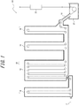
- the structure of a continuous hot-dip galvanizing device 100 used in a method for manufacturing a hot-dip galvanized steel sheet according to one of the disclosed embodiments will be described below, with reference to FIG. 1 .
- the continuous hot-dip galvanizing device 100 includes: a vertical annealing furnace 20 in which a heating zone 10, a soaking zone 12, and cooling zones 14 and 16 are arranged in this order; a hot-dip galvanizing bath 22 as a hot-dip galvanizing line located downstream of the cooling zone 16 in a steel sheet passing direction; and an alloying line 23 located downstream of the hot-dip galvanizing bath 22 in the steel sheet passing direction.
- the cooling zone includes a first cooling zone 14 (rapid cooling zone) and a second cooling zone 16 (slow cooling zone).
- a snout 18 connected to the second cooling zone 16 has its tip immersed in the hot-dip galvanizing bath 22, thus connecting the annealing furnace 20 and the hot-dip galvanizing bath 22.
- a steel sheet P is introduced from a steel sheet introduction port in the lower part of the heating zone 10 into the heating zone 10.
- One or more hearth rolls are arranged in the upper and lower parts in each of the zones 10, 12, 14, and 16.
- the steel sheet P is conveyed vertically a plurality of times inside the corresponding predetermined zone, forming a plurality of passes. While FIG. 1 illustrates an example of having 2 passes in the heating zone 10, 10 passes in the soaking zone 12, 2 passes in the first cooling zone 14, and 2 passes in the second cooling zone 16, the numbers of passes are not limited to such, and may be set as appropriate depending on the processing conditions.
- the steel sheet P is not folded back but changed in direction at the right angle to move to the next zone.
- the steel sheet P is thus annealed in the annealing furnace 20 by being conveyed through the heating zone 10, the soaking zone 12, and the cooling zones 14 and 16 in this order.
- Each of the zones 10, 12, 14, and 16 is a vertical furnace.
- the height of each zone is not limited, but may be about 20 m to 40 m.
- the length of each zone (the right-left direction in FIG. 1 ) may be determined as appropriate depending on the number of passes in the zone.
- the heating zone 10 with 2 passes may be about 0.8 m to 2 m
- the soaking zone 12 with 10 passes may be about 10 m to 20 m
- each of the first cooling zone 14 and the second cooling zone 16 with 2 passes may be about 0.8 m to 2 m.
- Adjacent zones in the annealing furnace 20 communicate through a communication portion connecting the upper parts or lower parts of the respective zones.
- the heating zone 10 and the soaking zone 12 communicate through a throat (restriction portion) connecting the lower parts of the respective zones.
- the soaking zone 12 and the first cooling zone 14 communicate through a throat connecting the lower parts of the respective zones.
- the first cooling zone 14 and the second cooling zone 16 communicate through a throat connecting the lower parts of the respective zones.
- the height of each throat may be set as appropriate, but is preferably as low as possible to enhance the independence of the atmosphere in each zone.
- the gas in the annealing furnace 20 flows from downstream to upstream in the furnace, and is discharged from the steel sheet introduction port in the lower part of the heating zone 10.
- the heating zone 10 is capable of indirectly heating the steel sheet P using a radiant tube (RT) or an electric heater.
- the average temperature in the heating zone 10 is preferably adjusted to 700 °C to 900 °C.
- the gas from the soaking zone 12 flows into the heating zone 10, and simultaneously reducing gas or non-oxidizing gas is supplied into the heating zone 10.
- As the reducing gas H 2 -N 2 mixed gas is typically used.
- An example of the non-oxidizing gas is gas (dew point: about -60 °C) having a composition containing N 2 and inevitable impurities.
- the supply of the gas to the heating zone 10 is not limited, but the gas is preferably supplied from introduction ports in two or more locations in the height direction and one or more locations in the longitudinal direction so that the gas is evenly introduced into the heating zone.
- the flow rate of the gas supplied to the heating zone is measured by a gas flowmeter (not illustrated) provided in the pipe.
- the flow rate is not limited, but may be about 10 to 100 (Nm 3 /hr).
- the soaking zone 12 is capable of indirectly heating the steel sheet P using a radiant tube (not illustrated) as heating means.
- the average temperature in the soaking zone 12 is preferably adjusted to 700 °C to 1000 °C.
- Reducing gas or non-oxidizing gas is supplied to the soaking zone 12.
- the reducing gas H 2 -N 2 mixed gas is typically used.
- An example is gas (dew point: about -60 °C) having a composition containing 1 vol% to 20 vol% H 2 with the balance being N 2 and inevitable impurities.
- An example of the non-oxidizing gas is gas (dew point: about -60 °C) having a composition containing N 2 and inevitable impurities.
- the reducing gas or non-oxidizing gas supplied to the soaking zone 12 has two forms, namely, humidified gas and dry gas.
- dry gas is reducing gas or non-oxidizing gas having a dew point of about -60 °C to -50 °C and not humidified by a humidifying device
- humidityidified gas is gas humidified by the humidifying device so that the dew point is 0 °C to 30 °C.
- the humidified gas is supplied to the soaking zone 12 in addition to the dry gas, in order to increase the dew point in the soaking zone.
- the dry gas is supplied to the soaking zone 12 without supplying the humidified gas, to prevent oxidation of the steel sheet surface.
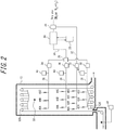
- FIG. 2 is a schematic diagram illustrating a supply system of humidified gas and dry gas to the soaking zone 12.
- the humidified gas is supplied through three systems, namely, humidified gas supply ports 42A, 42B, and 42C, humidified gas supply ports 44A, 44B, and 44C, and humidified gas supply ports 46A, 46B, and 46C.
- a gas distribution device 24 feeds part of the reducing gas or non-oxidizing gas (dry gas) into a humidifying device 26, and the remaining part through a dry gas pipe 32 into the soaking zone 12 from dry gas supply ports 48A, 48B, 48C, and 48D as dry gas.
- Reference sign 33 is a dry gas flowmeter.
- the positions and the number of the dry gas supply ports are not limited, and may be determined as appropriate based on various conditions.
- a plurality of dry gas supply ports are located at the same height position along the longitudinal direction of the soaking zone.
- the dry gas supply ports are evenly distributed in the longitudinal direction of the soaking zone.
- the gas humidified by the humidifying device 26 passes through a humidified gas pipe 34, is distributed among the three systems by a humidified gas distribution device 30, and supplied through respective humidified gas pipes 36 into the soaking zone 12 from humidified gas supply ports 42A to 42C, humidified gas supply ports 44A to 44C, and humidified gas supply ports 46A to 46C.
- a humidified gas supply port is provided at one or more locations in each of four sections formed by dividing the soaking zone 12 into halves in the vertical direction and into halves in the horizontal direction (i.e. entrance to exit direction). This enables uniform dew point control of the whole soaking zone 12.
- Reference sign 38 is a humidified gas flowmeter
- reference sign 40 is a humidified gas dew point meter.
- the dew point meter 40 is desirably located immediately in front of each of the humidified gas supply ports 42, 44, and 46.
- the humidifying device 26 includes a humidifying module having a fluorine or polyimide hollow fiber membrane, flat membrane, or the like. Dry gas flows inside the membrane, whereas pure water adjusted to a predetermined temperature in a circulating constant-temperature water bath 28 circulates outside the membrane.
- the fluorine or polyimide hollow fiber membrane or flat membrane is a type of ion exchange membrane with affinity for water molecules.
- the dry gas is humidified to the same dew point as the set water temperature, thus achieving highly accurate dew point control.
- the dew point of the humidified gas can be controlled to any value in the range of 5 °C to 50 °C.
- the flow rate and dew point of the humidified gas based on the degree of decarburization of the steel sheet caused by the moisture of the humidified gas supplied into the soaking zone.
- the soaking zone is humidified so that the dew point of the soaking zone is -20 °C or more, moisture and Si react to facilitate internal oxidation of Si in the steel sheet surface layer, and also moisture and carbon in the steel sheet surface layer react to cause a decarburization phenomenon. This reaction is expressed as: H 2 O + C ⁇ H 2 + CO.
- a CO gas concentration meter 60 is provided in an exhaust portion for gas in the soaking zone to measure the CO gas concentration, as illustrated in FIG. 2 .
- the thickness of the decarburized layer (decarburized layer thickness) of the steel sheet is calculated from the measured CO concentration, and at least one of the flow rate and dew point of the humidified gas (i.e. the amount of moisture supplied to the soaking zone) is controlled so that the calculated decarburized layer thickness is less than or equal to a predetermined thickness.
- D 9.53 ⁇ 10 ⁇ 7 ⁇ V ⁇ Gco / LS ⁇ W ⁇ C
- D the decarburized layer thickness [ ⁇ m]
- V the amount of gas flowing into the soaking zone [Nm 3 /hr]
- Gco the CO gas concentration [ppm]
- LS the sheet passing speed [m/s]
- W the sheet width of the steel sheet [m]
- C the carbon content of the steel sheet [mass%].
- the gas in the annealing furnace 20 flows from downstream to upstream in the furnace, and is discharged from the steel sheet introduction port in the lower part of the heating zone 10.
- the amount of gas flowing into the soaking zone 12 is the sum of the flow rate of the humidified gas and dry gas charged into the soaking zone 12 and the flow rate of the gas charged into the cooling zones 14 and 16.
- the decarburized layer thickness D is 20 ⁇ m or less.
- the changed value is substituted into Formula (1).
- the CO gas concentration Gco is then continuously monitored, and at least one of the flow rate and dew point of the humidified gas is controlled so that D is less than or equal to the predetermined value.
- the CO concentration is desirably measured at the gas outlet where the gas in the soaking zone gathers.
- the gas in the soaking zone 12 flows to the heating zone 10 and is used as the gas for the heating zone.
- the CO concentration meter 60 is desirably located at the connecting portion between the heating zone and the soaking zone, as illustrated in FIG. 2 .
- the flow rate of the humidified gas supplied into the soaking zone 12 is not limited as long as the foregoing control is performed, but is roughly maintained in the range of 100 to 400 (Nm 3 /hr).
- the flow rate of the dry gas supplied into the soaking zone 12 is not limited, but is roughly maintained in the range of 10 to 300 (Nm 3 /hr) when passing a high tensile strength steel sheet having a chemical composition containing 0.2 mass% or more Si.
- the cooling zones 14 and 16 cool the steel sheet P.
- the steel sheet P is cooled to about 480 °C to 530 °C in the first cooling zone 14, and cooled to about 470 °C to 500 °C in the second cooling zone 16.
- the cooling zones 14 and 16 are also supplied with the aforementioned reducing gas or non-oxidizing gas.
- the dry gas is supplied.
- the supply of the dry gas to the cooling zones 14 and 16 is not limited, but the dry gas is preferably supplied from introduction ports in two or more locations in the height direction and two or more locations in the longitudinal direction so that the dry gas is evenly introduced into the cooling zones.
- the total gas flow rate of the dry gas supplied to the cooling zones 14 and 16 is measured by a gas flowmeter (not illustrated) provided in the pipe.
- the total gas flow rate is not limited, but may be about 200 to 1000 (Nm 3 /hr).
- the hot-dip galvanizing bath 22 can be used to apply a hot-dip galvanized coating onto the steel sheet P discharged from the second cooling zone 16.
- the hot-dip galvanizing may be performed according to a usual method.
- the alloying line 23 can be used to heat-alloy the galvanized coating applied on the steel sheet P.
- the alloying treatment may be performed according to a usual method.
- the alloying temperature is kept from being high, thus preventing a decrease of the tensile strength of the produced galvannealed steel sheet.
- the alloying line 23 and the alloying treatment by the alloying line 23 are not essential in the present disclosure. The effect of obtaining favorable coating appearance and high tensile strength can be achieved even without alloying treatment.
- the steel sheet P subjected to annealing and hot-dip galvanizing is not limited, but the advantageous effects according to the present disclosure can be effectively achieved in the case where the steel sheet has a chemical composition in which Si content is 0.2 mass% or more, i.e. high tensile strength steel.
- a preferred chemical composition of the steel sheet will be described below. In the following description, "%" denotes mass%.
- the C content is preferably 0.025 % or more, but no lower limit is placed on the C content in the present disclosure. If the C content is more than 0.3 %, weldability decreases. The C content is therefore preferably 0.3 % or less.
- the Si is an element effective in strengthening the steel to obtain favorable material. Accordingly, for high tensile strength steel sheets, the Si content is set to 0.2 % or more. If the Si content is less than 0.2 %, an expensive alloying element is required in order to obtain high strength. If the Si content is more than 2.5 %, oxide layer formation in oxidation treatment is inhibited. Besides, the alloying temperature increases, making it difficult to achieve desired mechanical properties.
- the Si content is therefore preferably 2.5 % or less.
- Mn is an element effective in strengthening the steel. To ensure a tensile strength of 590 MPa or more, the Mn content is preferably 0.5 % or more. If the Mn content is more than 3.0 %, it may be difficult to ensure weldability, coating adhesion, and strength-ductility balance. The Mn content is therefore preferably 0.5 % to 3.0 %. For a tensile strength of 270 MPa to 440 MPa, Mn is added as appropriate in the range of 1.5 % or less.
- the P is an element effective in strengthening the steel, but delays alloying reaction between zinc and steel. Accordingly, in the case where the Si content in the steel is 0.2 % or more, the P content is preferably 0.03 % or less. Otherwise, P is added as appropriate depending on the strength. In terms of refining cost, the P content is preferably 0.001 % or more.
- the S content is therefore preferably 0.005 % or less. In terms of refining cost, the S content is preferably 0.0002 % or more.
- one or more of elements such as Cr, Mo, Ti, Nb, V, and B may be optionally added.
- the balance is Fe and inevitable impurities.
- the continuous hot-dip galvanizing device illustrated in FIGS. 1 and 2 was used to anneal each steel sheet whose chemical composition is shown in Table 1 (the balance being Fe and inevitable impurities) under the annealing conditions shown in Table 2, and then hot-dip galvanize and alloy the steel sheet.
- a RT furnace having a volume of 200 m 3 was used as the heating zone.
- the average temperature in the heating zone was set to 700 °C to 800 °C.
- gas (dew point: -50 °C) having a composition containing 15 vol% H 2 with the balance being N 2 and inevitable impurities was used as dry gas supplied into the heating zone.
- the flow rate of the dry gas into the heating zone was set to 100 Nm 3 /hr.
- a RT furnace having a volume of 700 m 3 was used as the soaking zone.
- the average temperature in the soaking zone was set to the value shown in Table 2.
- gas dew point: -50 °C
- Part of the dry gas was humidified by the humidifying device having a hollow fiber membrane-type humidifying portion, to prepare humidified gas.
- the hollow fiber membrane-type humidifying portion was made up of 10 membrane modules, in which circulating water of 100 L/min at the maximum was flown. Dry gas supply ports and humidified gas supply ports were arranged at the positions illustrated in FIG. 2 .
- the flow rates of the dry gas and the humidified gas supplied into the soaking zone are shown in Table 2.
- the "dew point” for the soaking zone indicates the dew point in the soaking zone measured at the position of a dew point measurement port 50 in FIG. 2 .
- the “humidified gas dew point” for the soaking zone indicates the dew point measured by the humidified gas dew point meter 40 in FIG. 2 .
- the dry gas (dew point: -50 °C) was supplied to the first and second cooling zones from their lowermost parts with the flow rate shown in Table 2.
- the temperature of the molten bath was set to 460 °C
- the Al concentration in the molten bath was set to 0.130 %
- the coating weight was adjusted to 50 g/m 2 per side by gas wiping.
- alloying treatment was performed in an induction heating-type alloying furnace so that the coating alloying degree (Fe content) was 10 % to 13 %.
- the alloying temperature in the treatment is shown in Table 2.
- No. 1 and No. 5 in Table 2 are Comparative Examples not supplied with humidified gas.
- the target decarburized layer thickness was set to 20 ⁇ m or less.
- the "calculated decarburized layer thickness D" in Table 2 indicates the decarburized layer thickness calculated by substituting the CO concentration Gco, the sheet passing speed LS, the sheet width W of the steel sheet, the C content of the steel sheet, and the amount V of gas flowing into the soaking zone (the sum of the humidified gas flow rate and the dry gas flow rate of the soaking zone and the gas flow rate of the cooling zone) into Formula (1).
- the “decarburized layer evaluation” in Table 2 indicates “good” in the case where the calculated decarburized layer thickness D was less than or equal to the target decarburized layer thickness, and “poor” in the case where the calculated decarburized layer thickness D was more than the target decarburized layer thickness.
- the evaluation of the coating appearance was conducted through inspection by an optical surface defect meter (detection of non-coating defects of ⁇ 0.5 or more or roll pick-up flaws) and visual determination of alloying unevenness. Samples accepted on all criteria were rated “good”, samples having a low degree of alloying unevenness were rated “fair”, and samples rejected on at least one of the criteria were rated “poor”. The results are shown in Table 2.
- steel with steel sample ID A was rated as "pass” when the tensile strength was 980 MPa or more, and steel with steel sample ID B was rated as "pass” when the tensile strength was 780 MPa or more.
- the results are shown in Table 2.
- a hot-dip galvanized steel sheet having excellent coating appearance and high tensile strength can be stably manufactured by monitoring the CO concentration during operation and controlling the humidified gas so that the decarburized layer thickness calculated from the measured CO concentration is less than or equal to a predetermined thickness.
Landscapes
- Chemical & Material Sciences (AREA)
- Engineering & Computer Science (AREA)
- Organic Chemistry (AREA)
- Materials Engineering (AREA)
- Mechanical Engineering (AREA)
- Metallurgy (AREA)
- Chemical Kinetics & Catalysis (AREA)
- Physics & Mathematics (AREA)
- Thermal Sciences (AREA)
- Crystallography & Structural Chemistry (AREA)
- Oil, Petroleum & Natural Gas (AREA)
- Coating With Molten Metal (AREA)
- Heat Treatment Of Strip Materials And Filament Materials (AREA)
Applications Claiming Priority (2)
| Application Number | Priority Date | Filing Date | Title |
|---|---|---|---|
| JP2017094930A JP6455544B2 (ja) | 2017-05-11 | 2017-05-11 | 溶融亜鉛めっき鋼板の製造方法 |
| PCT/JP2018/015737 WO2018207560A1 (fr) | 2017-05-11 | 2018-04-16 | Procédé de fabrication de tôle d'acier galvanisée à chaud |
Publications (3)
| Publication Number | Publication Date |
|---|---|
| EP3623492A1 true EP3623492A1 (fr) | 2020-03-18 |
| EP3623492A4 EP3623492A4 (fr) | 2020-07-15 |
| EP3623492B1 EP3623492B1 (fr) | 2021-02-17 |
Family
ID=64104478
Family Applications (1)
| Application Number | Title | Priority Date | Filing Date |
|---|---|---|---|
| EP18797789.7A Active EP3623492B1 (fr) | 2017-05-11 | 2018-04-16 | Procédé de fabrication de tôle d'acier galvanisée à chaud |
Country Status (7)
| Country | Link |
|---|---|
| US (1) | US11421312B2 (fr) |
| EP (1) | EP3623492B1 (fr) |
| JP (1) | JP6455544B2 (fr) |
| KR (1) | KR102263798B1 (fr) |
| CN (1) | CN110612359B (fr) |
| MX (1) | MX2019013411A (fr) |
| WO (1) | WO2018207560A1 (fr) |
Cited By (1)
| Publication number | Priority date | Publication date | Assignee | Title |
|---|---|---|---|---|
| EP4663782A4 (fr) * | 2023-04-28 | 2026-04-15 | Jfe Steel Corp | Procédé de fabrication d'une tôle d'acier galvanisée par immersion à chaud |
Families Citing this family (14)
| Publication number | Priority date | Publication date | Assignee | Title |
|---|---|---|---|---|
| JP7148438B2 (ja) * | 2018-03-05 | 2022-10-05 | 株式会社神戸製鋼所 | 酸化膜の膜厚測定方法 |
| CN109371325A (zh) * | 2018-11-30 | 2019-02-22 | 宝山钢铁股份有限公司 | 一种冷弯性能优良的锌系镀覆热成型钢板或钢带及其制造方法 |
| KR102648242B1 (ko) * | 2018-12-19 | 2024-03-18 | 주식회사 포스코 | 전기 저항 점용접성이 우수한 고강도 아연도금강판 및 그 제조방법 |
| US11384419B2 (en) * | 2019-08-30 | 2022-07-12 | Micromaierials Llc | Apparatus and methods for depositing molten metal onto a foil substrate |
| KR102312423B1 (ko) * | 2019-11-28 | 2021-10-12 | 현대제철 주식회사 | 핫스탬핑 가열로의 이슬점 제어장치 및 그 방법 |
| KR20210069757A (ko) * | 2019-12-03 | 2021-06-14 | 주식회사 포스코 | 표면품질과 점 용접성이 우수한 아연도금강판 및 그 제조방법 |
| KR102330604B1 (ko) | 2019-12-03 | 2021-11-24 | 주식회사 포스코 | 전기저항 점용접부의 피로강도가 우수한 아연도금강판 및 그 제조방법 |
| CN113063192B (zh) * | 2021-04-06 | 2022-08-19 | 首钢京唐钢铁联合有限责任公司 | 一种加湿装置以及加湿方法 |
| WO2023286501A1 (fr) * | 2021-07-14 | 2023-01-19 | Jfeスチール株式会社 | Procédé de production d'une tôle d'acier galvanisée à chaud |
| CN114196809A (zh) * | 2021-12-21 | 2022-03-18 | 新疆八一钢铁股份有限公司 | 一种降低钢坯加热脱碳的方法 |
| JP7401857B2 (ja) * | 2022-03-25 | 2023-12-20 | Jfeスチール株式会社 | 溶融亜鉛系めっき鋼板の製造方法 |
| KR102950029B1 (ko) * | 2023-09-15 | 2026-04-09 | 현대제철 주식회사 | 연속 소둔로 청정화 설비 및 방법 |
| JP2025185868A (ja) * | 2024-06-11 | 2025-12-23 | Jfeスチール株式会社 | 亜鉛めっき鋼板の製造設備、および、亜鉛めっき鋼板の製造方法 |
| JP7740442B1 (ja) * | 2024-06-11 | 2025-09-17 | Jfeスチール株式会社 | 鋼板の連続焼鈍設備、鋼板の連続焼鈍方法、および、亜鉛めっき鋼板の製造方法 |
Family Cites Families (15)
| Publication number | Priority date | Publication date | Assignee | Title |
|---|---|---|---|---|
| JPH0860254A (ja) * | 1994-08-17 | 1996-03-05 | Nippon Steel Corp | 連続焼鈍炉における雰囲気流れ制御方法 |
| US6591215B1 (en) * | 1999-02-18 | 2003-07-08 | Furnace Control Corp. | Systems and methods for controlling the activity of carbon in heat treating atmospheres |
| JP4192051B2 (ja) * | 2003-08-19 | 2008-12-03 | 新日本製鐵株式会社 | 高強度合金化溶融亜鉛めっき鋼板の製造方法と製造設備 |
| CN101287854B (zh) | 2005-10-14 | 2011-04-20 | 新日本制铁株式会社 | 含Si钢板的连续退火热浸镀方法以及连续退火热浸镀装置 |
| JP5119903B2 (ja) * | 2007-12-20 | 2013-01-16 | Jfeスチール株式会社 | 高強度溶融亜鉛めっき鋼板および高強度合金化溶融亜鉛めっき鋼板の製造方法 |
| JP5720084B2 (ja) | 2009-03-06 | 2015-05-20 | Jfeスチール株式会社 | 連続溶融亜鉛めっき装置および溶融亜鉛めっき鋼板の製造方法 |
| JP2012012683A (ja) | 2010-07-02 | 2012-01-19 | Sumitomo Metal Ind Ltd | 溶融亜鉛めっき鋼板の製造方法 |
| DE102011051731B4 (de) * | 2011-07-11 | 2013-01-24 | Thyssenkrupp Steel Europe Ag | Verfahren zur Herstellung eines durch Schmelztauchbeschichten mit einer metallischen Schutzschicht versehenen Stahlflachprodukts |
| MX370268B (es) * | 2012-08-03 | 2019-12-09 | Nippon Steel Corp Star | Lamina de acero galvanizada por inmersion en caliente y metodo de fabricacion de la misma. |
| JP5799997B2 (ja) * | 2013-09-12 | 2015-10-28 | Jfeスチール株式会社 | 外観性とめっき密着性に優れる溶融亜鉛めっき鋼板および合金化溶融亜鉛めっき鋼板ならびにそれらの製造方法 |
| JP5799996B2 (ja) * | 2013-09-12 | 2015-10-28 | Jfeスチール株式会社 | 外観性とめっき密着性に優れる溶融亜鉛めっき鋼板および合金化溶融亜鉛めっき鋼板ならびにそれらの製造方法 |
| CN106029932B (zh) * | 2014-02-25 | 2019-03-15 | 杰富意钢铁株式会社 | 还原炉的露点控制方法以及还原炉 |
| JP6301824B2 (ja) | 2014-12-18 | 2018-03-28 | 株式会社神戸製鋼所 | 鋼板およびその製造方法 |
| JP6792563B2 (ja) * | 2015-04-22 | 2020-11-25 | コケリル メンテナンス アンド インジェニエリー ソシエテ アノニム | 反応制御のための方法及び装置 |
| JP6439654B2 (ja) * | 2015-10-27 | 2018-12-19 | Jfeスチール株式会社 | 溶融亜鉛めっき鋼板の製造方法 |
-
2017
- 2017-05-11 JP JP2017094930A patent/JP6455544B2/ja active Active
-
2018
- 2018-04-16 MX MX2019013411A patent/MX2019013411A/es unknown
- 2018-04-16 CN CN201880030312.3A patent/CN110612359B/zh active Active
- 2018-04-16 US US16/607,813 patent/US11421312B2/en active Active
- 2018-04-16 WO PCT/JP2018/015737 patent/WO2018207560A1/fr not_active Ceased
- 2018-04-16 KR KR1020197033005A patent/KR102263798B1/ko active Active
- 2018-04-16 EP EP18797789.7A patent/EP3623492B1/fr active Active
Cited By (1)
| Publication number | Priority date | Publication date | Assignee | Title |
|---|---|---|---|---|
| EP4663782A4 (fr) * | 2023-04-28 | 2026-04-15 | Jfe Steel Corp | Procédé de fabrication d'une tôle d'acier galvanisée par immersion à chaud |
Also Published As
| Publication number | Publication date |
|---|---|
| WO2018207560A1 (fr) | 2018-11-15 |
| KR20190138664A (ko) | 2019-12-13 |
| CN110612359A (zh) | 2019-12-24 |
| MX2019013411A (es) | 2020-01-13 |
| EP3623492B1 (fr) | 2021-02-17 |
| EP3623492A4 (fr) | 2020-07-15 |
| JP2018188717A (ja) | 2018-11-29 |
| KR102263798B1 (ko) | 2021-06-10 |
| CN110612359B (zh) | 2021-09-03 |
| US20200190652A1 (en) | 2020-06-18 |
| US11421312B2 (en) | 2022-08-23 |
| JP6455544B2 (ja) | 2019-01-23 |
Similar Documents
| Publication | Publication Date | Title |
|---|---|---|
| EP3623492B1 (fr) | Procédé de fabrication de tôle d'acier galvanisée à chaud | |
| EP3243924B1 (fr) | Procédé de fabrication de tôle d'acier allié galvanisée par immersion à chaud | |
| EP3168321B1 (fr) | Procédé de fabrication de tôle d'acier allié galvanisé | |
| EP3730662B1 (fr) | Procédé de production de tôle d'acier galvanisée par immersion à chaud et appareil de galvanisation en continu par immersion à chaud | |
| US11649520B2 (en) | Continuous hot dip galvanizing apparatus | |
| EP3112493B1 (fr) | Méthode de régulation du point de rosée d'un four de réduction, et four de réduction | |
| EP3276037B1 (fr) | Procédé de fabrication de tôle d'acier galvanisée par immersion à chaud | |
| EP3369836B1 (fr) | Procédé de fabrication de tôle d'acier galvanisée par trempage à chaud | |
| EP4310207A1 (fr) | Procédé de régulation de point de rosée d'un four de recuit continu, procédé de recuit continu pour tôles d'acier, procédé de production de tôle d'acier, four de recuit continu, installation de galvanisation par immersion à chaud continue et installation de galvanisation par immersion à chaud alliée | |
| CN117616146A (zh) | 热镀锌钢板的制造方法 |
Legal Events
| Date | Code | Title | Description |
|---|---|---|---|
| STAA | Information on the status of an ep patent application or granted ep patent |
Free format text: STATUS: THE INTERNATIONAL PUBLICATION HAS BEEN MADE |
|
| PUAI | Public reference made under article 153(3) epc to a published international application that has entered the european phase |
Free format text: ORIGINAL CODE: 0009012 |
|
| STAA | Information on the status of an ep patent application or granted ep patent |
Free format text: STATUS: REQUEST FOR EXAMINATION WAS MADE |
|
| 17P | Request for examination filed |
Effective date: 20191121 |
|
| AK | Designated contracting states |
Kind code of ref document: A1 Designated state(s): AL AT BE BG CH CY CZ DE DK EE ES FI FR GB GR HR HU IE IS IT LI LT LU LV MC MK MT NL NO PL PT RO RS SE SI SK SM TR |
|
| AX | Request for extension of the european patent |
Extension state: BA ME |
|
| A4 | Supplementary search report drawn up and despatched |
Effective date: 20200615 |
|
| RIC1 | Information provided on ipc code assigned before grant |
Ipc: C22C 38/00 20060101ALI20200608BHEP Ipc: C21D 1/76 20060101ALI20200608BHEP Ipc: C21D 9/46 20060101ALI20200608BHEP Ipc: C22C 38/04 20060101ALI20200608BHEP Ipc: C23C 2/40 20060101ALI20200608BHEP Ipc: C23C 2/02 20060101AFI20200608BHEP Ipc: C23C 2/06 20060101ALI20200608BHEP Ipc: C21D 9/56 20060101ALI20200608BHEP |
|
| DAV | Request for validation of the european patent (deleted) | ||
| DAX | Request for extension of the european patent (deleted) | ||
| GRAP | Despatch of communication of intention to grant a patent |
Free format text: ORIGINAL CODE: EPIDOSNIGR1 |
|
| STAA | Information on the status of an ep patent application or granted ep patent |
Free format text: STATUS: GRANT OF PATENT IS INTENDED |
|
| INTG | Intention to grant announced |
Effective date: 20201009 |
|
| GRAS | Grant fee paid |
Free format text: ORIGINAL CODE: EPIDOSNIGR3 |
|
| GRAA | (expected) grant |
Free format text: ORIGINAL CODE: 0009210 |
|
| STAA | Information on the status of an ep patent application or granted ep patent |
Free format text: STATUS: THE PATENT HAS BEEN GRANTED |
|
| AK | Designated contracting states |
Kind code of ref document: B1 Designated state(s): AL AT BE BG CH CY CZ DE DK EE ES FI FR GB GR HR HU IE IS IT LI LT LU LV MC MK MT NL NO PL PT RO RS SE SI SK SM TR |
|
| REG | Reference to a national code |
Ref country code: GB Ref legal event code: FG4D |
|
| REG | Reference to a national code |
Ref country code: CH Ref legal event code: EP |
|
| REG | Reference to a national code |
Ref country code: DE Ref legal event code: R096 Ref document number: 602018012793 Country of ref document: DE |
|
| REG | Reference to a national code |
Ref country code: AT Ref legal event code: REF Ref document number: 1361550 Country of ref document: AT Kind code of ref document: T Effective date: 20210315 |
|
| REG | Reference to a national code |
Ref country code: IE Ref legal event code: FG4D |
|
| REG | Reference to a national code |
Ref country code: LT Ref legal event code: MG9D |
|
| REG | Reference to a national code |
Ref country code: NL Ref legal event code: MP Effective date: 20210217 |
|
| PG25 | Lapsed in a contracting state [announced via postgrant information from national office to epo] |
Ref country code: PT Free format text: LAPSE BECAUSE OF FAILURE TO SUBMIT A TRANSLATION OF THE DESCRIPTION OR TO PAY THE FEE WITHIN THE PRESCRIBED TIME-LIMIT Effective date: 20210617 Ref country code: NO Free format text: LAPSE BECAUSE OF FAILURE TO SUBMIT A TRANSLATION OF THE DESCRIPTION OR TO PAY THE FEE WITHIN THE PRESCRIBED TIME-LIMIT Effective date: 20210517 Ref country code: LT Free format text: LAPSE BECAUSE OF FAILURE TO SUBMIT A TRANSLATION OF THE DESCRIPTION OR TO PAY THE FEE WITHIN THE PRESCRIBED TIME-LIMIT Effective date: 20210217 Ref country code: BG Free format text: LAPSE BECAUSE OF FAILURE TO SUBMIT A TRANSLATION OF THE DESCRIPTION OR TO PAY THE FEE WITHIN THE PRESCRIBED TIME-LIMIT Effective date: 20210517 Ref country code: GR Free format text: LAPSE BECAUSE OF FAILURE TO SUBMIT A TRANSLATION OF THE DESCRIPTION OR TO PAY THE FEE WITHIN THE PRESCRIBED TIME-LIMIT Effective date: 20210518 Ref country code: HR Free format text: LAPSE BECAUSE OF FAILURE TO SUBMIT A TRANSLATION OF THE DESCRIPTION OR TO PAY THE FEE WITHIN THE PRESCRIBED TIME-LIMIT Effective date: 20210217 Ref country code: FI Free format text: LAPSE BECAUSE OF FAILURE TO SUBMIT A TRANSLATION OF THE DESCRIPTION OR TO PAY THE FEE WITHIN THE PRESCRIBED TIME-LIMIT Effective date: 20210217 |
|
| REG | Reference to a national code |
Ref country code: AT Ref legal event code: MK05 Ref document number: 1361550 Country of ref document: AT Kind code of ref document: T Effective date: 20210217 |
|
| PG25 | Lapsed in a contracting state [announced via postgrant information from national office to epo] |
Ref country code: LV Free format text: LAPSE BECAUSE OF FAILURE TO SUBMIT A TRANSLATION OF THE DESCRIPTION OR TO PAY THE FEE WITHIN THE PRESCRIBED TIME-LIMIT Effective date: 20210217 Ref country code: PL Free format text: LAPSE BECAUSE OF FAILURE TO SUBMIT A TRANSLATION OF THE DESCRIPTION OR TO PAY THE FEE WITHIN THE PRESCRIBED TIME-LIMIT Effective date: 20210217 Ref country code: NL Free format text: LAPSE BECAUSE OF FAILURE TO SUBMIT A TRANSLATION OF THE DESCRIPTION OR TO PAY THE FEE WITHIN THE PRESCRIBED TIME-LIMIT Effective date: 20210217 Ref country code: RS Free format text: LAPSE BECAUSE OF FAILURE TO SUBMIT A TRANSLATION OF THE DESCRIPTION OR TO PAY THE FEE WITHIN THE PRESCRIBED TIME-LIMIT Effective date: 20210217 Ref country code: SE Free format text: LAPSE BECAUSE OF FAILURE TO SUBMIT A TRANSLATION OF THE DESCRIPTION OR TO PAY THE FEE WITHIN THE PRESCRIBED TIME-LIMIT Effective date: 20210217 |
|
| PG25 | Lapsed in a contracting state [announced via postgrant information from national office to epo] |
Ref country code: IS Free format text: LAPSE BECAUSE OF FAILURE TO SUBMIT A TRANSLATION OF THE DESCRIPTION OR TO PAY THE FEE WITHIN THE PRESCRIBED TIME-LIMIT Effective date: 20210617 |
|
| PG25 | Lapsed in a contracting state [announced via postgrant information from national office to epo] |
Ref country code: EE Free format text: LAPSE BECAUSE OF FAILURE TO SUBMIT A TRANSLATION OF THE DESCRIPTION OR TO PAY THE FEE WITHIN THE PRESCRIBED TIME-LIMIT Effective date: 20210217 Ref country code: CZ Free format text: LAPSE BECAUSE OF FAILURE TO SUBMIT A TRANSLATION OF THE DESCRIPTION OR TO PAY THE FEE WITHIN THE PRESCRIBED TIME-LIMIT Effective date: 20210217 Ref country code: SM Free format text: LAPSE BECAUSE OF FAILURE TO SUBMIT A TRANSLATION OF THE DESCRIPTION OR TO PAY THE FEE WITHIN THE PRESCRIBED TIME-LIMIT Effective date: 20210217 Ref country code: AT Free format text: LAPSE BECAUSE OF FAILURE TO SUBMIT A TRANSLATION OF THE DESCRIPTION OR TO PAY THE FEE WITHIN THE PRESCRIBED TIME-LIMIT Effective date: 20210217 |
|
| REG | Reference to a national code |
Ref country code: DE Ref legal event code: R097 Ref document number: 602018012793 Country of ref document: DE |
|
| PG25 | Lapsed in a contracting state [announced via postgrant information from national office to epo] |
Ref country code: DK Free format text: LAPSE BECAUSE OF FAILURE TO SUBMIT A TRANSLATION OF THE DESCRIPTION OR TO PAY THE FEE WITHIN THE PRESCRIBED TIME-LIMIT Effective date: 20210217 Ref country code: SK Free format text: LAPSE BECAUSE OF FAILURE TO SUBMIT A TRANSLATION OF THE DESCRIPTION OR TO PAY THE FEE WITHIN THE PRESCRIBED TIME-LIMIT Effective date: 20210217 Ref country code: RO Free format text: LAPSE BECAUSE OF FAILURE TO SUBMIT A TRANSLATION OF THE DESCRIPTION OR TO PAY THE FEE WITHIN THE PRESCRIBED TIME-LIMIT Effective date: 20210217 Ref country code: MC Free format text: LAPSE BECAUSE OF FAILURE TO SUBMIT A TRANSLATION OF THE DESCRIPTION OR TO PAY THE FEE WITHIN THE PRESCRIBED TIME-LIMIT Effective date: 20210217 |
|
| PLBE | No opposition filed within time limit |
Free format text: ORIGINAL CODE: 0009261 |
|
| STAA | Information on the status of an ep patent application or granted ep patent |
Free format text: STATUS: NO OPPOSITION FILED WITHIN TIME LIMIT |
|
| PG25 | Lapsed in a contracting state [announced via postgrant information from national office to epo] |
Ref country code: LU Free format text: LAPSE BECAUSE OF NON-PAYMENT OF DUE FEES Effective date: 20210416 |
|
| REG | Reference to a national code |
Ref country code: BE Ref legal event code: MM Effective date: 20210430 |
|
| 26N | No opposition filed |
Effective date: 20211118 |
|
| PG25 | Lapsed in a contracting state [announced via postgrant information from national office to epo] |
Ref country code: ES Free format text: LAPSE BECAUSE OF FAILURE TO SUBMIT A TRANSLATION OF THE DESCRIPTION OR TO PAY THE FEE WITHIN THE PRESCRIBED TIME-LIMIT Effective date: 20210217 Ref country code: LI Free format text: LAPSE BECAUSE OF NON-PAYMENT OF DUE FEES Effective date: 20210430 Ref country code: CH Free format text: LAPSE BECAUSE OF NON-PAYMENT OF DUE FEES Effective date: 20210430 Ref country code: AL Free format text: LAPSE BECAUSE OF FAILURE TO SUBMIT A TRANSLATION OF THE DESCRIPTION OR TO PAY THE FEE WITHIN THE PRESCRIBED TIME-LIMIT Effective date: 20210217 |
|
| PG25 | Lapsed in a contracting state [announced via postgrant information from national office to epo] |
Ref country code: SI Free format text: LAPSE BECAUSE OF FAILURE TO SUBMIT A TRANSLATION OF THE DESCRIPTION OR TO PAY THE FEE WITHIN THE PRESCRIBED TIME-LIMIT Effective date: 20210217 |
|
| PG25 | Lapsed in a contracting state [announced via postgrant information from national office to epo] |
Ref country code: IT Free format text: LAPSE BECAUSE OF FAILURE TO SUBMIT A TRANSLATION OF THE DESCRIPTION OR TO PAY THE FEE WITHIN THE PRESCRIBED TIME-LIMIT Effective date: 20210217 Ref country code: IE Free format text: LAPSE BECAUSE OF NON-PAYMENT OF DUE FEES Effective date: 20210416 |
|
| PG25 | Lapsed in a contracting state [announced via postgrant information from national office to epo] |
Ref country code: IS Free format text: LAPSE BECAUSE OF FAILURE TO SUBMIT A TRANSLATION OF THE DESCRIPTION OR TO PAY THE FEE WITHIN THE PRESCRIBED TIME-LIMIT Effective date: 20210617 |
|
| PG25 | Lapsed in a contracting state [announced via postgrant information from national office to epo] |
Ref country code: BE Free format text: LAPSE BECAUSE OF NON-PAYMENT OF DUE FEES Effective date: 20210430 |
|
| PG25 | Lapsed in a contracting state [announced via postgrant information from national office to epo] |
Ref country code: CY Free format text: LAPSE BECAUSE OF FAILURE TO SUBMIT A TRANSLATION OF THE DESCRIPTION OR TO PAY THE FEE WITHIN THE PRESCRIBED TIME-LIMIT Effective date: 20210217 |
|
| PG25 | Lapsed in a contracting state [announced via postgrant information from national office to epo] |
Ref country code: HU Free format text: LAPSE BECAUSE OF FAILURE TO SUBMIT A TRANSLATION OF THE DESCRIPTION OR TO PAY THE FEE WITHIN THE PRESCRIBED TIME-LIMIT; INVALID AB INITIO Effective date: 20180416 |
|
| PG25 | Lapsed in a contracting state [announced via postgrant information from national office to epo] |
Ref country code: MK Free format text: LAPSE BECAUSE OF FAILURE TO SUBMIT A TRANSLATION OF THE DESCRIPTION OR TO PAY THE FEE WITHIN THE PRESCRIBED TIME-LIMIT Effective date: 20210217 |
|
| PGFP | Annual fee paid to national office [announced via postgrant information from national office to epo] |
Ref country code: GB Payment date: 20240229 Year of fee payment: 7 |
|
| PG25 | Lapsed in a contracting state [announced via postgrant information from national office to epo] |
Ref country code: TR Free format text: LAPSE BECAUSE OF FAILURE TO SUBMIT A TRANSLATION OF THE DESCRIPTION OR TO PAY THE FEE WITHIN THE PRESCRIBED TIME-LIMIT Effective date: 20210217 |
|
| PG25 | Lapsed in a contracting state [announced via postgrant information from national office to epo] |
Ref country code: MT Free format text: LAPSE BECAUSE OF FAILURE TO SUBMIT A TRANSLATION OF THE DESCRIPTION OR TO PAY THE FEE WITHIN THE PRESCRIBED TIME-LIMIT Effective date: 20210217 |
|
| PGFP | Annual fee paid to national office [announced via postgrant information from national office to epo] |
Ref country code: DE Payment date: 20250305 Year of fee payment: 8 |
|
| GBPC | Gb: european patent ceased through non-payment of renewal fee |
Effective date: 20250416 |
|
| PG25 | Lapsed in a contracting state [announced via postgrant information from national office to epo] |
Ref country code: GB Free format text: LAPSE BECAUSE OF NON-PAYMENT OF DUE FEES Effective date: 20250416 |
|
| PGFP | Annual fee paid to national office [announced via postgrant information from national office to epo] |
Ref country code: FR Payment date: 20260309 Year of fee payment: 9 |