EP3623636A1 - Système pour circulation de gaz dans de espaces annulaires de machines tournantes - Google Patents
Système pour circulation de gaz dans de espaces annulaires de machines tournantes Download PDFInfo
- Publication number
- EP3623636A1 EP3623636A1 EP18797718.6A EP18797718A EP3623636A1 EP 3623636 A1 EP3623636 A1 EP 3623636A1 EP 18797718 A EP18797718 A EP 18797718A EP 3623636 A1 EP3623636 A1 EP 3623636A1
- Authority
- EP
- European Patent Office
- Prior art keywords
- gas
- pump
- ejector
- fluid
- rotor
- Prior art date
- Legal status (The legal status is an assumption and is not a legal conclusion. Google has not performed a legal analysis and makes no representation as to the accuracy of the status listed.)
- Granted
Links
Images


Classifications
-
- F—MECHANICAL ENGINEERING; LIGHTING; HEATING; WEAPONS; BLASTING
- F04—POSITIVE - DISPLACEMENT MACHINES FOR LIQUIDS; PUMPS FOR LIQUIDS OR ELASTIC FLUIDS
- F04D—NON-POSITIVE-DISPLACEMENT PUMPS
- F04D29/00—Details, component parts, or accessories
- F04D29/58—Cooling; Heating; Diminishing heat transfer
- F04D29/5806—Cooling the drive system
-
- F—MECHANICAL ENGINEERING; LIGHTING; HEATING; WEAPONS; BLASTING
- F04—POSITIVE - DISPLACEMENT MACHINES FOR LIQUIDS; PUMPS FOR LIQUIDS OR ELASTIC FLUIDS
- F04D—NON-POSITIVE-DISPLACEMENT PUMPS
- F04D13/00—Pumping installations or systems
- F04D13/02—Units comprising pumps and their driving means
- F04D13/06—Units comprising pumps and their driving means the pump being electrically driven
- F04D13/08—Units comprising pumps and their driving means the pump being electrically driven for submerged use
- F04D13/086—Units comprising pumps and their driving means the pump being electrically driven for submerged use the pump and drive motor are both submerged
-
- F—MECHANICAL ENGINEERING; LIGHTING; HEATING; WEAPONS; BLASTING
- F04—POSITIVE - DISPLACEMENT MACHINES FOR LIQUIDS; PUMPS FOR LIQUIDS OR ELASTIC FLUIDS
- F04F—PUMPING OF FLUID BY DIRECT CONTACT OF ANOTHER FLUID OR BY USING INERTIA OF FLUID TO BE PUMPED; SIPHONS
- F04F5/00—Jet pumps, i.e. devices in which flow is induced by pressure drop caused by velocity of another fluid flow
- F04F5/02—Jet pumps, i.e. devices in which flow is induced by pressure drop caused by velocity of another fluid flow the inducing fluid being liquid
- F04F5/04—Jet pumps, i.e. devices in which flow is induced by pressure drop caused by velocity of another fluid flow the inducing fluid being liquid displacing elastic fluids
-
- F—MECHANICAL ENGINEERING; LIGHTING; HEATING; WEAPONS; BLASTING
- F04—POSITIVE - DISPLACEMENT MACHINES FOR LIQUIDS; PUMPS FOR LIQUIDS OR ELASTIC FLUIDS
- F04F—PUMPING OF FLUID BY DIRECT CONTACT OF ANOTHER FLUID OR BY USING INERTIA OF FLUID TO BE PUMPED; SIPHONS
- F04F5/00—Jet pumps, i.e. devices in which flow is induced by pressure drop caused by velocity of another fluid flow
- F04F5/54—Installations characterised by use of jet pumps, e.g. combinations of two or more jet pumps of different type
-
- F—MECHANICAL ENGINEERING; LIGHTING; HEATING; WEAPONS; BLASTING
- F01—MACHINES OR ENGINES IN GENERAL; ENGINE PLANTS IN GENERAL; STEAM ENGINES
- F01P—COOLING OF MACHINES OR ENGINES IN GENERAL; COOLING OF INTERNAL-COMBUSTION ENGINES
- F01P5/00—Pumping cooling-air or liquid coolants
- F01P5/02—Pumping cooling-air; Arrangements of cooling-air pumps, e.g. fans or blowers
-
- F—MECHANICAL ENGINEERING; LIGHTING; HEATING; WEAPONS; BLASTING
- F04—POSITIVE - DISPLACEMENT MACHINES FOR LIQUIDS; PUMPS FOR LIQUIDS OR ELASTIC FLUIDS
- F04D—NON-POSITIVE-DISPLACEMENT PUMPS
- F04D7/00—Pumps adapted for handling specific fluids, e.g. by selection of specific materials for pumps or pump parts
- F04D7/02—Pumps adapted for handling specific fluids, e.g. by selection of specific materials for pumps or pump parts of centrifugal type
- F04D7/04—Pumps adapted for handling specific fluids, e.g. by selection of specific materials for pumps or pump parts of centrifugal type the fluids being viscous or non-homogenous
-
- F—MECHANICAL ENGINEERING; LIGHTING; HEATING; WEAPONS; BLASTING
- F04—POSITIVE - DISPLACEMENT MACHINES FOR LIQUIDS; PUMPS FOR LIQUIDS OR ELASTIC FLUIDS
- F04F—PUMPING OF FLUID BY DIRECT CONTACT OF ANOTHER FLUID OR BY USING INERTIA OF FLUID TO BE PUMPED; SIPHONS
- F04F5/00—Jet pumps, i.e. devices in which flow is induced by pressure drop caused by velocity of another fluid flow
- F04F5/14—Jet pumps, i.e. devices in which flow is induced by pressure drop caused by velocity of another fluid flow the inducing fluid being elastic fluid
- F04F5/16—Jet pumps, i.e. devices in which flow is induced by pressure drop caused by velocity of another fluid flow the inducing fluid being elastic fluid displacing elastic fluids
- F04F5/20—Jet pumps, i.e. devices in which flow is induced by pressure drop caused by velocity of another fluid flow the inducing fluid being elastic fluid displacing elastic fluids for evacuating
-
- H—ELECTRICITY
- H02—GENERATION; CONVERSION OR DISTRIBUTION OF ELECTRIC POWER
- H02K—DYNAMO-ELECTRIC MACHINES
- H02K5/00—Casings; Enclosures; Supports
- H02K5/04—Casings or enclosures characterised by the shape, form or construction thereof
- H02K5/12—Casings or enclosures characterised by the shape, form or construction thereof specially adapted for operating in liquid or gas
- H02K5/132—Submersible electric motors
Definitions
- the present invention is a system for injecting gases into air gaps of rotating machines, through an ejector, pump and a motor.
- Such system may be used in subsea equipment, subsea pumping, subsea engines, subsea compressors, rotating machines.
- the production of reservoir fluids typically contains a mixture of hydrocarbons, gas and oil, along with water and sand.
- the largest fraction of oil production is obtained, which is the most profitable component, while the water fraction is lowest.
- the well production curve over the time describes significant inversion with which fluid fractions are produced. Throughout the well lifetime there is a need for using artificial lifting methods so that the recovered oil fraction remains profitable.
- Subsea pumping encompasses different technologies of motors and pumps, in order to match equipment functions to system requirements, and its characteristics, such as required head pressure ("head”), fluid composition, fraction of gas (“gas volume fraction” - GVF), viscosity, WC variations ("watercut”), presence of emulsions and representative amounts of sand.
- head head pressure
- fluid composition fraction of gas
- viscosity WC variations
- watercut watercut
- Helical-axial and centrifugal hydraulics have been adopted by the market for subsea pumping.
- Subsea pumps have been used in deep water depths, e.g., above 1000 m, and may be located inside the oil well or in subsea bed. From the aforementioned applications, the adoption of centrifugal pump may require a well drilled exclusively for its installation, which receives the production of reservoir fluids, coming from production well, and may also require the gas be separated to achieve remain gas contents acceptable to enter the pump without causing any damage.
- centrifugal pumps can tolerate around 20% of gas volume fraction in production stream to be pumped. Intervention on equipment when it is installed inside a well is very costly when compared to intervention on equipment when it is installed in a seabed, even causing production interruption.
- the helical-axial hydraulic pumps have greater tolerance to the gas fractions to be pumped along with liquid fractions and, moreover, are installed in a subsea bed.
- a pumping or compression system consists of a motor and a pump or compressor itself.
- the motor rotor is coupled to the pump shaft and may be the same shaft in some applications.
- the pump or compressor is also composed of a rotating part, coupled to the shaft, called impellers, which are components responsible for transferring energy to the fluid, in addition, the pump has static components, called diffusers, whose function is to condition the flow.
- impellers rotating part coupled to the shaft
- diffusers static components
- Electric motors used to drive devices where pressurized process fluid is present must be designed to prevent process fluid from entering the motor.
- One solution is to separate the motor and pump into individual housings so that any leak is collected outside the system.
- housings In a subsea system, housings generally communicate with each other, having a mechanical seal as a barrier between them. However, because it is a dynamic seal, a small leakage of fluid occurs from the high-pressure side to the low-pressure side. This seal is then pressurized by the motor side with a barrier fluid, causing a leak in the pump direction.
- barrier fluid should have controlled electrical characteristics, generally being a dielectric mineral oil, contaminant-free and with controlled water concentration.
- Some systems may use fluids with softer specifications, for example, in coiled wire motors, where electrical fluid characteristics are not crucial.
- Barrier fluid can be either a fluid with well-defined electrical characteristics such as a dielectric mineral oil, or a fluid with softer specifications, such as where motor windings are wired. In addition to the main barrier function, this fluid also has the secondary function for cooling the motor.
- the barrier fluid system requires that it be installed on topside utilities, a skid with hydraulic panels and an umbilical-connected mineral fluid reservoir for continuous supply of barrier fluid to subsea equipment. The need for a barrier fluid system results in operational supervision and cost to operation since barrier fluid is consumable and requires periodic replacement.
- barrier fluid has the disadvantage: the requirement for a dedicated system for surface unit fluid supply, typically located on the platform Turret, occupies umbilical lines with fluid transfer to the motor, requires operators' supervision and maintenance, consumes platform energy.
- barrier fluid which is most often a liquid, also presents significant losses due to the drag generated by the relative movement between the static and the rotating part. Therefore, the presence of a viscous fluid in the motor gap may mean a low efficiency for a large diameter or high-speed motor and may make the machine operation impracticable.
- a second solution is to drain the gap constantly, removing mainly gas.
- the process fluid pressure is greater than the gap pressure, causing the process fluid leak to gap, therefore this drain is also responsible for removing this liquid and directing it to another point of the system.
- the present invention relates to a system for injecting gas into the air gaps of rotating machines ("air gap") (20), such system comprises the use of a pump (32), a motor (18) and an ejector (10).
- air gap air gap
- the present invention has two embodiments.
- the first embodiment features a system (30) which allows a reduction in fluid viscosity in the air gap ("air gap") (20) between rotor (28) and stator (26) of motor (18), wherein this low viscosity fluid (12) coming from discharge (58) of ejector (10), where this low viscosity fluid (12) is the result of mixing a gas (08) from the gas-extraction unit (24) of pump (32) with a motivation fluid (48) coming from discharge (14) of pump (32).
- the second embodiment features a system (40) allowing for reduction of viscosity of fluid in air gap ("air gap") (20) between rotor (28) and stator (26) of motor (18), wherein a gas (08) from a gas-extraction unit (24) circulates through air gap ("air gap") (20) and thereafter through an ejector (10) the fluid (12) flows to the process line upstream of pump (32).
- the present invention describes systems for injecting gas into the air gaps of rotating machines ("air gap") (20), such systems comprise the use of a pump (32), a motor (18) and an ejector (10).
- air gap air gap
- the present invention by way of illustration, will describe two embodiments.
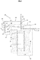
- the present invention uses an ejector (10) which is an equipment for suctioning or pressurizing fluids, as can be seen in Fig. 1 , the ejector (10) consisting of a converging nozzle (02) ("nozzle") having a motivating inlet (22) and a narrowing (16) in its outlet, further provided with a perpendicular suction inlet (54), said converging nozzle (02) and suction inlet (54) both being interconnected to a throat (04) where the mixture of suction gas (08) and motivation fluid (48) occur, and said throat (04) being continued by a diffuser (06), which is responsible for the pressurization of mixture of gas (08) and motivation fluid (48) and therefore conditioning the discharge fluid (12) to the required pressure.
- a converging nozzle (02) ("nozzle") having a motivating inlet (22) and a narrowing (16) in its outlet, further provided with a perpendicular suction inlet (54), said converging nozzle (02) and suction inlet
- the low pressure generated causes a pressure differential between the suction inlet (54) and the throat (04), receiving fluid at certain P s e Q s (suction pressure and flow) by means suction inlet (54).
- a diffuser (06) is responsible for converting speed again into pressure, and thus the pressure in discharge (58) of ejector (10) may be sized intermediate the motivation pressure and suction pressure.
- the invention described below encompasses two embodiments using an ejector (10), in order to provide separate gas recirculating through air gap (20) ("air gap").
- the first embodiment of the system for injecting gas into the air gaps of rotating machines (30), represented by the schematic in Fig. 2 , comprises an ejector (10) which uses as motivation fluid (48) the discharge fluid line (36) of pump (32), said ejector (10) being connected to discharge line (36) through pipe (44).
- the embodiment of system (30) also comprises a pump (32) having in its constitution a gas-extraction unit (24) responsible for extracting from the fluid of the process line (34), the gas (08) to be used by the ejector (10).
- the embodiment of the system (30) also has a motor (18) consisting of a stator (26) and a rotor (28), wherein this rotor (28) is coupled to shaft of pump (32), and wherein rotor (28) surrounded by stator (26) forms an air gap (20) ("air gap").
- a motor (18) consisting of a stator (26) and a rotor (28), wherein this rotor (28) is coupled to shaft of pump (32), and wherein rotor (28) surrounded by stator (26) forms an air gap (20) ("air gap").
- the mixture of gas (08) and motivation fluid (48) occurs in throat (04) of ejector (10) and then is pressurized by diffuser (06) and injected in air gap (20) between rotor (28) and stator (26) by means of a pipe (38).
- the fluid from discharge (12) of ejector (10) contains very high GVF ("gas volume fraction") content, such characteristic conditions the gas, along with some remaining fluid, to be mostly circulated by air gap ("air gap") (20) through a pipe (38), and therefore, a very low viscosity fluid in air gap ("air gap”) (20) is obtained, which implies in minimal drag losses, to which the rotating and static surfaces may be subjected to.
- GVF gas volume fraction
- air gap (20) Following the discharge fluid circulates through air gap (20), it is injected in process line (34) through a pipe (42) upstream of pump (32).
- process line (34) Following the discharge fluid circulates through air gap (20), it is injected in process line (34) through a pipe (42) upstream of pump (32).
- air gap air gap
- Such configuration may be used in systems requiring a fluid be circulated with high pressure by air gap ("air gap”) (20), and accordingly certain liquid amount may be received and drained from air gap (“air gap”) (20).
- the second embodiment of the system for injecting gas into the air gaps of rotating machines (40), represented by the schematic in Fig. 3 , comprises an ejector (10) which uses, as motivation fluid (48), the discharge fluid line (36) from pump (32), said ejector (10) being connected to the discharge line (36) through pipe (44).
- the embodiment of system (40) also comprises a pump (32) having in its constitution a gas-extraction unit (24) responsible for extracting fluid from process line (34), the gas (08).
- the embodiment of system (40) also has a motor (18) consisting of a stator (26) and a rotor (28), wherein such rotor (28) is connected to the shaft of pump (32), and wherein rotor (28) surrounded by stator (26) forms an air gap (20) ("air gap").
- a motor (18) consisting of a stator (26) and a rotor (28), wherein such rotor (28) is connected to the shaft of pump (32), and wherein rotor (28) surrounded by stator (26) forms an air gap (20) ("air gap").
- Said gas (08), from gas-extraction unit (24), is sucked by ejector (10), via suction inlet (54), in order to circulate in air gap (20) before being pressurized by ejector (10).
- the gas-extraction unit (24) is connected to the air gap (20) of motor (18) through pipe (50), and air gap (20) of motor (18) is connected to suction inlet (54) of ejector (10) through pipe (52).
- Ejector (10) is responsible for mixing the gas (08) coming from air gap (20) with motivation fluid (48), said mixing occurs in throat (04) of ejector (10) and afterwards it is pressurized by diffuser (06) and injected in process line (34) through pipe (38) connecting the discharge (58) of ejector (10) to said process line (34) upstream of pump (32).
- the gas (08) does not circulate with very high GVF, however when air gap (20) sucks gas (08) from gas-extraction unit (24), a very low viscosity fluid circulates in air gap. Therefore, this configuration may be used in systems where the operating pressure in air gap ("air gap") (20) is approximately equal to suction pressure of pump (32).
Landscapes
- Engineering & Computer Science (AREA)
- Mechanical Engineering (AREA)
- General Engineering & Computer Science (AREA)
- Physics & Mathematics (AREA)
- Fluid Mechanics (AREA)
- Thermal Sciences (AREA)
- Jet Pumps And Other Pumps (AREA)
- Life Sciences & Earth Sciences (AREA)
- Geology (AREA)
- Mining & Mineral Resources (AREA)
- Power Engineering (AREA)
- Environmental & Geological Engineering (AREA)
- General Life Sciences & Earth Sciences (AREA)
- Geochemistry & Mineralogy (AREA)
- Structures Of Non-Positive Displacement Pumps (AREA)
Applications Claiming Priority (2)
| Application Number | Priority Date | Filing Date | Title |
|---|---|---|---|
| BR102017009824-9A BR102017009824B1 (pt) | 2017-05-10 | 2017-05-10 | Sistema para circulação de gás em espaços anulares de máquinas rotativas |
| PCT/BR2018/050152 WO2018205002A1 (fr) | 2017-05-10 | 2018-05-09 | Système pour circulation de gaz dans de espaces annulaires de machines tournantes |
Publications (3)
| Publication Number | Publication Date |
|---|---|
| EP3623636A1 true EP3623636A1 (fr) | 2020-03-18 |
| EP3623636A4 EP3623636A4 (fr) | 2021-01-13 |
| EP3623636B1 EP3623636B1 (fr) | 2024-09-11 |
Family
ID=64104107
Family Applications (1)
| Application Number | Title | Priority Date | Filing Date |
|---|---|---|---|
| EP18797718.6A Active EP3623636B1 (fr) | 2017-05-10 | 2018-05-09 | Système pour circulation de gaz dans de espaces annulaires de machines tournantes |
Country Status (4)
| Country | Link |
|---|---|
| US (1) | US11603861B2 (fr) |
| EP (1) | EP3623636B1 (fr) |
| BR (1) | BR102017009824B1 (fr) |
| WO (1) | WO2018205002A1 (fr) |
Cited By (1)
| Publication number | Priority date | Publication date | Assignee | Title |
|---|---|---|---|---|
| US11876434B2 (en) | 2021-09-03 | 2024-01-16 | Dana Limited | Air gap scavenging system for oil cooled electric motor |
Families Citing this family (2)
| Publication number | Priority date | Publication date | Assignee | Title |
|---|---|---|---|---|
| US11201524B2 (en) * | 2019-06-26 | 2021-12-14 | Hamilton Sundstrand Corporation | Motor cooling systems |
| DE102021118253B4 (de) * | 2021-07-14 | 2023-02-02 | Man Energy Solutions Se | Strömungsmaschinenanordnung |
Family Cites Families (17)
| Publication number | Priority date | Publication date | Assignee | Title |
|---|---|---|---|---|
| GB888211A (en) | 1956-12-05 | 1962-01-31 | G & J Weir Ltd | Improvements in or relating to pumps |
| US3514167A (en) | 1968-07-03 | 1970-05-26 | Caterpillar Tractor Co | Venturi-type oil seal system for engine crankshafts or the like |
| US3698839A (en) * | 1970-10-14 | 1972-10-17 | Borg Warner | Pressure equalizer for unloading a compressor during start-up |
| US5165248A (en) * | 1991-09-03 | 1992-11-24 | Carrier Corporation | Oil reclaim in a centrifugal chiller system |
| CH686525A5 (de) * | 1992-07-02 | 1996-04-15 | Escher Wyss Ag | Turbomaschine . |
| EP1069313B1 (fr) * | 1999-07-16 | 2005-09-14 | Man Turbo Ag | Turbo-compresseur |
| NO323324B1 (no) | 2003-07-02 | 2007-03-19 | Kvaerner Oilfield Prod As | Fremgangsmate for regulering at trykket i en undervannskompressormodul |
| GB2443117B (en) | 2003-12-20 | 2008-08-13 | Rolls Royce Plc | A seal arrangement |
| US7181928B2 (en) * | 2004-06-29 | 2007-02-27 | York International Corporation | System and method for cooling a compressor motor |
| US20080260539A1 (en) | 2005-10-07 | 2008-10-23 | Aker Kvaerner Subsea As | Apparatus and Method For Controlling Supply of Barrier Gas in a Compressor Module |
| NO328277B1 (no) * | 2008-04-21 | 2010-01-18 | Statoil Asa | Gasskompresjonssystem |
| US8899912B2 (en) * | 2009-01-15 | 2014-12-02 | Dresser-Rand Company | Shaft seal with convergent nozzle |
| TWI577949B (zh) * | 2013-02-21 | 2017-04-11 | 強生控制科技公司 | 潤滑及冷卻系統 |
| BR102013009262B1 (pt) | 2013-04-16 | 2021-03-09 | Fmc Technologies Do Brasil Ltda | estação integrada de produção submarina e processo de separação de água, òleo, gás e sólidos |
| US9874230B2 (en) * | 2014-04-15 | 2018-01-23 | Dresser-Rand Company | Gas takeoff isolation system |
| GB2536291A (en) * | 2015-03-13 | 2016-09-14 | Caltec Ltd | Jet pump |
| ITUB20152564A1 (it) * | 2015-07-28 | 2017-01-28 | Nuovo Pignone Tecnologie Srl | Motocompressore e metodo per migliorare l’efficienza di un motocompressore |
-
2017
- 2017-05-10 BR BR102017009824-9A patent/BR102017009824B1/pt active IP Right Grant
-
2018
- 2018-05-09 EP EP18797718.6A patent/EP3623636B1/fr active Active
- 2018-05-09 WO PCT/BR2018/050152 patent/WO2018205002A1/fr not_active Ceased
- 2018-05-09 US US16/613,080 patent/US11603861B2/en active Active
Cited By (2)
| Publication number | Priority date | Publication date | Assignee | Title |
|---|---|---|---|---|
| US11876434B2 (en) | 2021-09-03 | 2024-01-16 | Dana Limited | Air gap scavenging system for oil cooled electric motor |
| US12132381B2 (en) | 2021-09-03 | 2024-10-29 | Dana Limited | Air gap scavenging system for oil cooled electric motor |
Also Published As
| Publication number | Publication date |
|---|---|
| US20200340495A1 (en) | 2020-10-29 |
| US11603861B2 (en) | 2023-03-14 |
| BR102017009824A2 (pt) | 2018-12-04 |
| EP3623636B1 (fr) | 2024-09-11 |
| EP3623636A4 (fr) | 2021-01-13 |
| WO2018205002A1 (fr) | 2018-11-15 |
| BR102017009824B1 (pt) | 2023-12-19 |
Similar Documents
| Publication | Publication Date | Title |
|---|---|---|
| CN105408581B (zh) | 在井下和地面生产多相井流体的组合式泵和压缩机及方法 | |
| RU2659594C2 (ru) | Многоступенчатый центробежный насос с интегральными износостойкими упорными осевыми подшипниками | |
| US11603861B2 (en) | System for the circulation of gas in airs gaps of rotating machines | |
| WO2018077527A1 (fr) | Pompe polyphasique et procédé de fonctionnement de ladite pompe | |
| US20070187110A1 (en) | Method and apparatus for production in oil wells | |
| CN108119100A (zh) | 油井举升系统及其抽油方法 | |
| US12221868B2 (en) | Electric submersible pump (ESP) shroud system | |
| US20140174756A1 (en) | Artificial lift method for low pressure sagd wells | |
| US10385673B2 (en) | Fluid driven commingling system for oil and gas applications | |
| US20190093654A1 (en) | Downhole motor-pump assembly | |
| US12163525B2 (en) | Subsea pump system with process lubricated bearings | |
| JP6903539B2 (ja) | 圧縮機 | |
| US12503933B2 (en) | Electric submersible pump gas evacuation system | |
| WO2018057960A1 (fr) | Ensemble motopompe de fond de trou | |
| RU61369U1 (ru) | Компоновка погружной насосной установки | |
| Brandt et al. | Multiphase downhole screw assembly (MDA)-A new chapter in conveying hydrocarbons |
Legal Events
| Date | Code | Title | Description |
|---|---|---|---|
| STAA | Information on the status of an ep patent application or granted ep patent |
Free format text: STATUS: THE INTERNATIONAL PUBLICATION HAS BEEN MADE |
|
| PUAI | Public reference made under article 153(3) epc to a published international application that has entered the european phase |
Free format text: ORIGINAL CODE: 0009012 |
|
| STAA | Information on the status of an ep patent application or granted ep patent |
Free format text: STATUS: REQUEST FOR EXAMINATION WAS MADE |
|
| 17P | Request for examination filed |
Effective date: 20191206 |
|
| AK | Designated contracting states |
Kind code of ref document: A1 Designated state(s): AL AT BE BG CH CY CZ DE DK EE ES FI FR GB GR HR HU IE IS IT LI LT LU LV MC MK MT NL NO PL PT RO RS SE SI SK SM TR |
|
| A4 | Supplementary search report drawn up and despatched |
Effective date: 20201211 |
|
| RIC1 | Information provided on ipc code assigned before grant |
Ipc: F04F 5/04 20060101ALI20201207BHEP Ipc: F04D 29/58 20060101ALI20201207BHEP Ipc: F16C 33/72 20060101ALI20201207BHEP Ipc: F04D 29/10 20060101AFI20201207BHEP Ipc: F16J 15/40 20060101ALI20201207BHEP Ipc: E21B 33/00 20060101ALI20201207BHEP Ipc: F04F 5/16 20060101ALI20201207BHEP Ipc: F04F 5/54 20060101ALI20201207BHEP Ipc: F04D 25/06 20060101ALI20201207BHEP Ipc: F04F 5/20 20060101ALI20201207BHEP |
|
| STAA | Information on the status of an ep patent application or granted ep patent |
Free format text: STATUS: EXAMINATION IS IN PROGRESS |
|
| 17Q | First examination report despatched |
Effective date: 20221110 |
|
| P01 | Opt-out of the competence of the unified patent court (upc) registered |
Effective date: 20230523 |
|
| GRAP | Despatch of communication of intention to grant a patent |
Free format text: ORIGINAL CODE: EPIDOSNIGR1 |
|
| STAA | Information on the status of an ep patent application or granted ep patent |
Free format text: STATUS: GRANT OF PATENT IS INTENDED |
|
| INTG | Intention to grant announced |
Effective date: 20240409 |
|
| GRAS | Grant fee paid |
Free format text: ORIGINAL CODE: EPIDOSNIGR3 |
|
| GRAA | (expected) grant |
Free format text: ORIGINAL CODE: 0009210 |
|
| STAA | Information on the status of an ep patent application or granted ep patent |
Free format text: STATUS: THE PATENT HAS BEEN GRANTED |
|
| AK | Designated contracting states |
Kind code of ref document: B1 Designated state(s): AL AT BE BG CH CY CZ DE DK EE ES FI FR GB GR HR HU IE IS IT LI LT LU LV MC MK MT NL NO PL PT RO RS SE SI SK SM TR |
|
| REG | Reference to a national code |
Ref country code: GB Ref legal event code: FG4D |
|
| REG | Reference to a national code |
Ref country code: CH Ref legal event code: EP |
|
| REG | Reference to a national code |
Ref country code: DE Ref legal event code: R096 Ref document number: 602018074300 Country of ref document: DE |
|
| REG | Reference to a national code |
Ref country code: IE Ref legal event code: FG4D |
|
| REG | Reference to a national code |
Ref country code: LT Ref legal event code: MG9D |
|
| REG | Reference to a national code |
Ref country code: NL Ref legal event code: MP Effective date: 20240911 |
|
| PG25 | Lapsed in a contracting state [announced via postgrant information from national office to epo] |
Ref country code: GR Free format text: LAPSE BECAUSE OF FAILURE TO SUBMIT A TRANSLATION OF THE DESCRIPTION OR TO PAY THE FEE WITHIN THE PRESCRIBED TIME-LIMIT Effective date: 20241212 Ref country code: FI Free format text: LAPSE BECAUSE OF FAILURE TO SUBMIT A TRANSLATION OF THE DESCRIPTION OR TO PAY THE FEE WITHIN THE PRESCRIBED TIME-LIMIT Effective date: 20240911 |
|
| PG25 | Lapsed in a contracting state [announced via postgrant information from national office to epo] |
Ref country code: BG Free format text: LAPSE BECAUSE OF FAILURE TO SUBMIT A TRANSLATION OF THE DESCRIPTION OR TO PAY THE FEE WITHIN THE PRESCRIBED TIME-LIMIT Effective date: 20240911 |
|
| PG25 | Lapsed in a contracting state [announced via postgrant information from national office to epo] |
Ref country code: LV Free format text: LAPSE BECAUSE OF FAILURE TO SUBMIT A TRANSLATION OF THE DESCRIPTION OR TO PAY THE FEE WITHIN THE PRESCRIBED TIME-LIMIT Effective date: 20240911 |
|
| PG25 | Lapsed in a contracting state [announced via postgrant information from national office to epo] |
Ref country code: HR Free format text: LAPSE BECAUSE OF FAILURE TO SUBMIT A TRANSLATION OF THE DESCRIPTION OR TO PAY THE FEE WITHIN THE PRESCRIBED TIME-LIMIT Effective date: 20240911 |
|
| PG25 | Lapsed in a contracting state [announced via postgrant information from national office to epo] |
Ref country code: RS Free format text: LAPSE BECAUSE OF FAILURE TO SUBMIT A TRANSLATION OF THE DESCRIPTION OR TO PAY THE FEE WITHIN THE PRESCRIBED TIME-LIMIT Effective date: 20241211 Ref country code: ES Free format text: LAPSE BECAUSE OF FAILURE TO SUBMIT A TRANSLATION OF THE DESCRIPTION OR TO PAY THE FEE WITHIN THE PRESCRIBED TIME-LIMIT Effective date: 20240911 |
|
| PG25 | Lapsed in a contracting state [announced via postgrant information from national office to epo] |
Ref country code: RS Free format text: LAPSE BECAUSE OF FAILURE TO SUBMIT A TRANSLATION OF THE DESCRIPTION OR TO PAY THE FEE WITHIN THE PRESCRIBED TIME-LIMIT Effective date: 20241211 Ref country code: LV Free format text: LAPSE BECAUSE OF FAILURE TO SUBMIT A TRANSLATION OF THE DESCRIPTION OR TO PAY THE FEE WITHIN THE PRESCRIBED TIME-LIMIT Effective date: 20240911 Ref country code: HR Free format text: LAPSE BECAUSE OF FAILURE TO SUBMIT A TRANSLATION OF THE DESCRIPTION OR TO PAY THE FEE WITHIN THE PRESCRIBED TIME-LIMIT Effective date: 20240911 Ref country code: GR Free format text: LAPSE BECAUSE OF FAILURE TO SUBMIT A TRANSLATION OF THE DESCRIPTION OR TO PAY THE FEE WITHIN THE PRESCRIBED TIME-LIMIT Effective date: 20241212 Ref country code: FI Free format text: LAPSE BECAUSE OF FAILURE TO SUBMIT A TRANSLATION OF THE DESCRIPTION OR TO PAY THE FEE WITHIN THE PRESCRIBED TIME-LIMIT Effective date: 20240911 Ref country code: ES Free format text: LAPSE BECAUSE OF FAILURE TO SUBMIT A TRANSLATION OF THE DESCRIPTION OR TO PAY THE FEE WITHIN THE PRESCRIBED TIME-LIMIT Effective date: 20240911 Ref country code: BG Free format text: LAPSE BECAUSE OF FAILURE TO SUBMIT A TRANSLATION OF THE DESCRIPTION OR TO PAY THE FEE WITHIN THE PRESCRIBED TIME-LIMIT Effective date: 20240911 |
|
| REG | Reference to a national code |
Ref country code: AT Ref legal event code: MK05 Ref document number: 1722909 Country of ref document: AT Kind code of ref document: T Effective date: 20240911 |
|
| PG25 | Lapsed in a contracting state [announced via postgrant information from national office to epo] |
Ref country code: NL Free format text: LAPSE BECAUSE OF FAILURE TO SUBMIT A TRANSLATION OF THE DESCRIPTION OR TO PAY THE FEE WITHIN THE PRESCRIBED TIME-LIMIT Effective date: 20240911 |
|
| PG25 | Lapsed in a contracting state [announced via postgrant information from national office to epo] |
Ref country code: PT Free format text: LAPSE BECAUSE OF FAILURE TO SUBMIT A TRANSLATION OF THE DESCRIPTION OR TO PAY THE FEE WITHIN THE PRESCRIBED TIME-LIMIT Effective date: 20250113 Ref country code: IS Free format text: LAPSE BECAUSE OF FAILURE TO SUBMIT A TRANSLATION OF THE DESCRIPTION OR TO PAY THE FEE WITHIN THE PRESCRIBED TIME-LIMIT Effective date: 20250111 |
|
| PG25 | Lapsed in a contracting state [announced via postgrant information from national office to epo] |
Ref country code: SM Free format text: LAPSE BECAUSE OF FAILURE TO SUBMIT A TRANSLATION OF THE DESCRIPTION OR TO PAY THE FEE WITHIN THE PRESCRIBED TIME-LIMIT Effective date: 20240911 Ref country code: RO Free format text: LAPSE BECAUSE OF FAILURE TO SUBMIT A TRANSLATION OF THE DESCRIPTION OR TO PAY THE FEE WITHIN THE PRESCRIBED TIME-LIMIT Effective date: 20240911 |
|
| PG25 | Lapsed in a contracting state [announced via postgrant information from national office to epo] |
Ref country code: EE Free format text: LAPSE BECAUSE OF FAILURE TO SUBMIT A TRANSLATION OF THE DESCRIPTION OR TO PAY THE FEE WITHIN THE PRESCRIBED TIME-LIMIT Effective date: 20240911 Ref country code: AT Free format text: LAPSE BECAUSE OF FAILURE TO SUBMIT A TRANSLATION OF THE DESCRIPTION OR TO PAY THE FEE WITHIN THE PRESCRIBED TIME-LIMIT Effective date: 20240911 |
|
| PG25 | Lapsed in a contracting state [announced via postgrant information from national office to epo] |
Ref country code: CZ Free format text: LAPSE BECAUSE OF FAILURE TO SUBMIT A TRANSLATION OF THE DESCRIPTION OR TO PAY THE FEE WITHIN THE PRESCRIBED TIME-LIMIT Effective date: 20240911 Ref country code: PL Free format text: LAPSE BECAUSE OF FAILURE TO SUBMIT A TRANSLATION OF THE DESCRIPTION OR TO PAY THE FEE WITHIN THE PRESCRIBED TIME-LIMIT Effective date: 20240911 |
|
| PG25 | Lapsed in a contracting state [announced via postgrant information from national office to epo] |
Ref country code: SK Free format text: LAPSE BECAUSE OF FAILURE TO SUBMIT A TRANSLATION OF THE DESCRIPTION OR TO PAY THE FEE WITHIN THE PRESCRIBED TIME-LIMIT Effective date: 20240911 |
|
| REG | Reference to a national code |
Ref country code: DE Ref legal event code: R097 Ref document number: 602018074300 Country of ref document: DE |
|
| PG25 | Lapsed in a contracting state [announced via postgrant information from national office to epo] |
Ref country code: DK Free format text: LAPSE BECAUSE OF FAILURE TO SUBMIT A TRANSLATION OF THE DESCRIPTION OR TO PAY THE FEE WITHIN THE PRESCRIBED TIME-LIMIT Effective date: 20240911 |
|
| PGFP | Annual fee paid to national office [announced via postgrant information from national office to epo] |
Ref country code: GB Payment date: 20250401 Year of fee payment: 8 |
|
| PGFP | Annual fee paid to national office [announced via postgrant information from national office to epo] |
Ref country code: NO Payment date: 20250509 Year of fee payment: 8 |
|
| PGFP | Annual fee paid to national office [announced via postgrant information from national office to epo] |
Ref country code: IT Payment date: 20250422 Year of fee payment: 8 |
|
| PGFP | Annual fee paid to national office [announced via postgrant information from national office to epo] |
Ref country code: FR Payment date: 20250401 Year of fee payment: 8 |
|
| PLBE | No opposition filed within time limit |
Free format text: ORIGINAL CODE: 0009261 |
|
| STAA | Information on the status of an ep patent application or granted ep patent |
Free format text: STATUS: NO OPPOSITION FILED WITHIN TIME LIMIT |
|
| 26N | No opposition filed |
Effective date: 20250612 |
|
| PG25 | Lapsed in a contracting state [announced via postgrant information from national office to epo] |
Ref country code: SE Free format text: LAPSE BECAUSE OF FAILURE TO SUBMIT A TRANSLATION OF THE DESCRIPTION OR TO PAY THE FEE WITHIN THE PRESCRIBED TIME-LIMIT Effective date: 20240911 |
|
| REG | Reference to a national code |
Ref country code: DE Ref legal event code: R119 Ref document number: 602018074300 Country of ref document: DE |
|
| REG | Reference to a national code |
Ref country code: CH Ref legal event code: H13 Free format text: ST27 STATUS EVENT CODE: U-0-0-H10-H13 (AS PROVIDED BY THE NATIONAL OFFICE) Effective date: 20251223 |
|
| PG25 | Lapsed in a contracting state [announced via postgrant information from national office to epo] |
Ref country code: LU Free format text: LAPSE BECAUSE OF NON-PAYMENT OF DUE FEES Effective date: 20250509 |
|
| PG25 | Lapsed in a contracting state [announced via postgrant information from national office to epo] |
Ref country code: CH Free format text: LAPSE BECAUSE OF NON-PAYMENT OF DUE FEES Effective date: 20250531 |
|
| REG | Reference to a national code |
Ref country code: BE Ref legal event code: MM Effective date: 20250531 |
|
| PG25 | Lapsed in a contracting state [announced via postgrant information from national office to epo] |
Ref country code: MC Free format text: LAPSE BECAUSE OF FAILURE TO SUBMIT A TRANSLATION OF THE DESCRIPTION OR TO PAY THE FEE WITHIN THE PRESCRIBED TIME-LIMIT Effective date: 20240911 |
|
| PG25 | Lapsed in a contracting state [announced via postgrant information from national office to epo] |
Ref country code: IE Free format text: LAPSE BECAUSE OF NON-PAYMENT OF DUE FEES Effective date: 20250509 Ref country code: DE Free format text: LAPSE BECAUSE OF NON-PAYMENT OF DUE FEES Effective date: 20251202 |
|
| PG25 | Lapsed in a contracting state [announced via postgrant information from national office to epo] |
Ref country code: BE Free format text: LAPSE BECAUSE OF NON-PAYMENT OF DUE FEES Effective date: 20250531 |