EP3623654B1 - Palier magnétique et accumulateur à volant d'inertie - Google Patents
Palier magnétique et accumulateur à volant d'inertie Download PDFInfo
- Publication number
- EP3623654B1 EP3623654B1 EP19197463.3A EP19197463A EP3623654B1 EP 3623654 B1 EP3623654 B1 EP 3623654B1 EP 19197463 A EP19197463 A EP 19197463A EP 3623654 B1 EP3623654 B1 EP 3623654B1
- Authority
- EP
- European Patent Office
- Prior art keywords
- rotor
- bearing
- magnetic
- ring
- axial
- Prior art date
- Legal status (The legal status is an assumption and is not a legal conclusion. Google has not performed a legal analysis and makes no representation as to the accuracy of the status listed.)
- Not-in-force
Links
Images



Classifications
-
- F—MECHANICAL ENGINEERING; LIGHTING; HEATING; WEAPONS; BLASTING
- F16—ENGINEERING ELEMENTS AND UNITS; GENERAL MEASURES FOR PRODUCING AND MAINTAINING EFFECTIVE FUNCTIONING OF MACHINES OR INSTALLATIONS; THERMAL INSULATION IN GENERAL
- F16C—SHAFTS; FLEXIBLE SHAFTS; ELEMENTS OR CRANKSHAFT MECHANISMS; ROTARY BODIES OTHER THAN GEARING ELEMENTS; BEARINGS
- F16C15/00—Construction of rotary bodies to resist centrifugal force
-
- F—MECHANICAL ENGINEERING; LIGHTING; HEATING; WEAPONS; BLASTING
- F16—ENGINEERING ELEMENTS AND UNITS; GENERAL MEASURES FOR PRODUCING AND MAINTAINING EFFECTIVE FUNCTIONING OF MACHINES OR INSTALLATIONS; THERMAL INSULATION IN GENERAL
- F16C—SHAFTS; FLEXIBLE SHAFTS; ELEMENTS OR CRANKSHAFT MECHANISMS; ROTARY BODIES OTHER THAN GEARING ELEMENTS; BEARINGS
- F16C32/00—Bearings not otherwise provided for
- F16C32/04—Bearings not otherwise provided for using magnetic or electric supporting means
- F16C32/0406—Magnetic bearings
- F16C32/0408—Passive magnetic bearings
- F16C32/041—Passive magnetic bearings with permanent magnets on one part attracting the other part
- F16C32/0412—Passive magnetic bearings with permanent magnets on one part attracting the other part for radial load mainly
-
- F—MECHANICAL ENGINEERING; LIGHTING; HEATING; WEAPONS; BLASTING
- F16—ENGINEERING ELEMENTS AND UNITS; GENERAL MEASURES FOR PRODUCING AND MAINTAINING EFFECTIVE FUNCTIONING OF MACHINES OR INSTALLATIONS; THERMAL INSULATION IN GENERAL
- F16C—SHAFTS; FLEXIBLE SHAFTS; ELEMENTS OR CRANKSHAFT MECHANISMS; ROTARY BODIES OTHER THAN GEARING ELEMENTS; BEARINGS
- F16C32/00—Bearings not otherwise provided for
- F16C32/04—Bearings not otherwise provided for using magnetic or electric supporting means
- F16C32/0406—Magnetic bearings
- F16C32/0408—Passive magnetic bearings
- F16C32/0423—Passive magnetic bearings with permanent magnets on both parts repelling each other
- F16C32/0429—Passive magnetic bearings with permanent magnets on both parts repelling each other for both radial and axial load, e.g. conical magnets
- F16C32/0431—Passive magnetic bearings with permanent magnets on both parts repelling each other for both radial and axial load, e.g. conical magnets with bearings for axial load combined with bearings for radial load
-
- F—MECHANICAL ENGINEERING; LIGHTING; HEATING; WEAPONS; BLASTING
- F16—ENGINEERING ELEMENTS AND UNITS; GENERAL MEASURES FOR PRODUCING AND MAINTAINING EFFECTIVE FUNCTIONING OF MACHINES OR INSTALLATIONS; THERMAL INSULATION IN GENERAL
- F16C—SHAFTS; FLEXIBLE SHAFTS; ELEMENTS OR CRANKSHAFT MECHANISMS; ROTARY BODIES OTHER THAN GEARING ELEMENTS; BEARINGS
- F16C32/00—Bearings not otherwise provided for
- F16C32/04—Bearings not otherwise provided for using magnetic or electric supporting means
- F16C32/0406—Magnetic bearings
- F16C32/044—Active magnetic bearings
- F16C32/0459—Details of the magnetic circuit
- F16C32/0461—Details of the magnetic circuit of stationary parts of the magnetic circuit
- F16C32/0465—Details of the magnetic circuit of stationary parts of the magnetic circuit with permanent magnets provided in the magnetic circuit of the electromagnets
-
- F—MECHANICAL ENGINEERING; LIGHTING; HEATING; WEAPONS; BLASTING
- F16—ENGINEERING ELEMENTS AND UNITS; GENERAL MEASURES FOR PRODUCING AND MAINTAINING EFFECTIVE FUNCTIONING OF MACHINES OR INSTALLATIONS; THERMAL INSULATION IN GENERAL
- F16C—SHAFTS; FLEXIBLE SHAFTS; ELEMENTS OR CRANKSHAFT MECHANISMS; ROTARY BODIES OTHER THAN GEARING ELEMENTS; BEARINGS
- F16C32/00—Bearings not otherwise provided for
- F16C32/04—Bearings not otherwise provided for using magnetic or electric supporting means
- F16C32/0406—Magnetic bearings
- F16C32/044—Active magnetic bearings
- F16C32/0459—Details of the magnetic circuit
- F16C32/0468—Details of the magnetic circuit of moving parts of the magnetic circuit, e.g. of the rotor
-
- F—MECHANICAL ENGINEERING; LIGHTING; HEATING; WEAPONS; BLASTING
- F16—ENGINEERING ELEMENTS AND UNITS; GENERAL MEASURES FOR PRODUCING AND MAINTAINING EFFECTIVE FUNCTIONING OF MACHINES OR INSTALLATIONS; THERMAL INSULATION IN GENERAL
- F16C—SHAFTS; FLEXIBLE SHAFTS; ELEMENTS OR CRANKSHAFT MECHANISMS; ROTARY BODIES OTHER THAN GEARING ELEMENTS; BEARINGS
- F16C2300/00—Application independent of particular apparatuses
- F16C2300/40—Application independent of particular apparatuses related to environment, i.e. operating conditions
- F16C2300/62—Application independent of particular apparatuses related to environment, i.e. operating conditions low pressure, e.g. elements operating under vacuum conditions
-
- F—MECHANICAL ENGINEERING; LIGHTING; HEATING; WEAPONS; BLASTING
- F16—ENGINEERING ELEMENTS AND UNITS; GENERAL MEASURES FOR PRODUCING AND MAINTAINING EFFECTIVE FUNCTIONING OF MACHINES OR INSTALLATIONS; THERMAL INSULATION IN GENERAL
- F16C—SHAFTS; FLEXIBLE SHAFTS; ELEMENTS OR CRANKSHAFT MECHANISMS; ROTARY BODIES OTHER THAN GEARING ELEMENTS; BEARINGS
- F16C2361/00—Apparatus or articles in engineering in general
- F16C2361/55—Flywheel systems
Definitions
- the invention relates to a magnetic bearing of a rotor according to the preamble of claim 1 and a flywheel storage device designed with such a magnetic bearing.
- Rolling and plain bearings are conventionally used to support rotors, in which the contact surfaces are acted upon by a liquid or gaseous lubricant, so that wear and friction are minimized.
- Such conventional bearings reach their limits under certain operating conditions, for example at high or very low ambient temperatures or at extremely high speeds, when used in a vacuum or with aggressive gases.
- non-contact bearings in particular magnetic bearings
- magnetic bearings are used.
- the basic structure of such a magnetic bearing is, for example, in DE 17 50 602 C3 and in the introduction to the description DE 10 2005 028 209 A1 described.
- such magnetic bearings have an axial bearing formed, for example, by a permanent magnet, the permanent magnet being designed in such a way that it bears the weight of the rotor in the axial direction.
- the storage in the radial direction takes place by means of electromagnets, each of which can be controlled via a control circuit.
- the radial position of the rotor is detected via position sensors, so that the electromagnets are controlled in each case via a control loop as a function of the signal from the respective position sensor.
- an active magnetic bearing is also used, the axial gap being detected by a further position sensor.
- a corresponding magnetic bearing is disclosed which is used for levitating a rotor of a flywheel.
- Such magnetic bearings are also used in turbo expansion turbines and compressors, air and gas compressors, vacuum pumps and centrifuges.
- a disadvantage of the above-described systems for levitating a rotor at a defined position in space by means of active field force bearings is that five degrees of freedom (four degrees of freedom in the radial direction, one degree of freedom in the axial direction) have to be actively controlled and, accordingly, five control loops with the associated power electronics and five position sensors required are. This represents a considerable effort in terms of energy, device technology and control technology.
- DE 10 2005 028 209 A1 describes a rotor shaft bearing in which the radial bearing is based on the reluctance principle.
- the radial bearing is based on the reluctance principle.
- separate means for generating a magnetic flux are required, so that the control and device engineering effort is high.
- a magnetic bearing with the features of the preamble of independent claim 1 is from DE 10 2005 030 139 A1 known.
- the invention is based on the object of creating a magnetic bearing which, with a compact structure, enables a rotor to be levitated with little effort.
- the invention is also based on the object of creating a flywheel accumulator, the rotor of which is levitated with little outlay in terms of control engineering and device engineering.
- a rotor is levitated in a housing or a frame by means of a magnetic bearing, which in principle has an axial and a radial bearing, each of which is designed as an active or permanent field force bearing (magnetic bearing).
- the magnetic bearing according to the invention has a position sensor for detecting the axial positions of the rotor and a control circuit for controlling the active axial field force bearing as a function of the signal from the position sensor.
- the radial bearing works according to the reluctance principle with a reluctance-based radial restoring effect, the system always striving for a minimum magnetic resistance that is given with a predetermined nominal position of the rotor with respect to the housing.
- the magnetic bearing also has an axial bearing with at least one permanent field force bearing, which is designed such that it can hold the weight of the rotor and the rotor is held with a predetermined axial gap with respect to a stator of the system.
- a magnetic coil that can be controlled by means of the control circuit is assigned to the permanent field force bearing, which strengthens the magnetic flux of the permanent field force bearing or weakens it when the current is in the opposite direction, so that the axial gap can be adjusted or kept constant depending on the signal from the position sensor by suitable control of the coil by means of the control circuit can.
- the at least one magnetic coil is preferably assigned to both the reluctance-based radial bearing and the active axial bearing.
- the radial rigidity of the magnetic bearing is not implemented via an active control loop, but rather automatically via the reluctance effects described above, the dynamic behavior of the overall system of the magnetic bearing can be easily modeled.
- the axial bearing is designed with two axially spaced permanent field force bearings, each of which is preferably assigned a magnetic coil which can be controlled via a common control circuit.
- These two permanent field force bearings acting in the axial direction are preferably provided in the area of the end sections of the rotor.
- the radial bearing arrangement has two radial bearings arranged at an axial distance, which both work according to the reluctance principle, the permanent field force bearing and the magnetic coil being arranged on a stator of the magnetic bearing and the stator being spaced apart by an axial gap from one connected or connected to the rotor is arranged in one piece with this trained rotor attachment.
- the radial rigidity of the magnetic bearing can be adjusted by slightly varying this geometry.
- the stator and the rotor attachment are formed at least in sections from a magnetically conductive material, preferably a soft magnetic material.
- the profiling on the stator and on the rotor attachment is formed by at least one axially protruding ring or an elevation, the reluctance-optimized flux shaping being effected in that the width of the ring or the elevation is the same on the stator and rotor side, so that if the rings / bumps are covered, the magnetic resistance and the flux density are minimal. It is particularly preferred if at least two concentric rings are formed on the rotor attachment and on the stator.
- the rotor attachment can also be designed in one piece with the rotor.
- additional, preferably circumferential, grooves can be formed on the rings / elevations protruding in the axial direction, these grooves being symmetrical on the stator and rotor side. With a radial displacement of the rotor, these additional grooves cause increased restoring forces (reluctance forces), which arise from the additionally induced distortions of the magnetic field lines.
- the rotor is preferably arranged vertically, the magnetic force generated by means of the permanent field force bearing compensating for the weight of the rotor.
- the rotor can run in a vacuum.
- the housing accommodating the rotor can be designed as a vacuum housing.
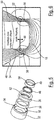
- Figure 1 shows an experimental set-up 1 with which the functionality of the magnetic bearing 2 according to the invention of a rotor 4 was confirmed.
- the rotor 4 is mounted in a frame 6.
- a housing preferably a vacuum housing, is then provided instead of the frame 6, in which the rotor 4, designed as a flywheel, is supported via the magnetic bearing 2.
- the in Figure 1 The experimental setup 1 shown in the figure, the rotor 4 is driven by a motor 8 held on the frame 6. In the experimental setup and also in the case of flywheel accumulators, the rotor 4 is upright, ie positioned with a rotor axis arranged in the vertical (direction of gravity). More details of the Experimental setup 1 are based on Figure 2 which shows a vertical section of the experimental setup 1.
- the magnetic bearing 2 has an upper bearing housing 10 and a lower bearing housing 12, which are fixed to the frame 6.
- a magnetic bearing (upper magnetic bearing 14, lower magnetic bearing 16) is arranged in each of the two bearing housings 10, 12, the structure of which is explained in more detail below.
- the rotor 4 has an upper rotor attachment 18, which is operatively connected to the magnetic bearings 14, 16, and a lower rotor attachment 20, which are each connected to the rotor 4 in a rotationally fixed manner.
- the in Figure 1 The indicated motor 8 is accommodated in a motor housing 22 which is fastened to the frame 6.
- a position sensor is arranged in the upper bearing housing 10, which measures the axial gap between a stator and the rotor.
- This position sensor is called axial sensor 23 in the following.
- FIG. 3 On the left the rotor 4 is shown alone, on the right enlarged representations of the upper magnetic bearing 14 and the lower magnetic bearing 16 and the associated components of the magnetic bearing 2 are shown. It can be seen that the rotor attachment 18, 20 is inserted into a corresponding receptacle 28, 30 of the upper or lower rotor end section via a radially recessed fastening pin 24, 26 that plunges into the rotor 4, so that the actual rotor attachment 18, 20 is in Axial direction extends out of the respective end face of the rotor 4.
- the structure of the upper and lower magnetic bearings 14, 16 is largely identical. As in Figure 3 shown, however, the lower rotor attachment 20 is designed so that it does not lie directly on the end face of the actual rotor 4, but is arranged at a distance from it. This spacing is made possible by an extension of the lower fastening pin 26. This axial spacing of the lower rotor attachment 20 with respect to the actual rotor 4 Space is created for receiving the lower magnetic bearing 16, the structure of which corresponds to that of the upper magnetic bearing 14.
- the upper magnetic bearing 14 has an outer bearing ring 32 which is screwed to the bearing housing 10 or 12 and thus forms part of the stator of the magnetic bearing.
- the outer bearing ring 32 is shown in FIG Figure 4 stepped back radially downwards, so that a receiving space 34 is formed, into which a coil holder 36 for a magnetic coil 38 is inserted.
- the bobbin holder 36 is supported inward in the radial direction by an inner bearing ring 40, which likewise dips into the receiving space 34 at least in sections.
- the inner bearing ring 40 and the outer bearing ring 32 are made of a magnetically conductive material, preferably a soft magnetic material, towards the rotor attachment 18, 20.
- the end sections on the rotor attachment side are designed with a geometry that leads to self-centering due to the reluctance forces.
- These end sections of the two bearing rings 32, 40 are referred to as flux shapers 48 and 50, respectively.
- At least these flux shapers 48, 50 are made of a magnetically conductive material in order to optimize self-centering.
- the two flux formers 48, 50 protrude towards the rotor attachment 18 beyond the coil carrier 36, these in the axial direction projecting end sections is formed by a respective tapering of the flow shapers 48, 50, so that two concentric ring structures 52, 54 of the flow shapers 48, 50 are formed on the end face.
- the width B of the inner ring structure 54 is greater than the width b of the outer ring structure 52.
- the rotor attachment 18 is designed with corresponding rings 56, 58, the geometry of which corresponds to that of the ring structure 52, 54.
- the nominal position shown is formed between the ring structures 52, 54 on the one hand and the rings 56, 58 on the other hand, an axial gap 60, which by means of the Figure 2 described axial sensor 23 is detected.
- Figure 5 shows the components of the magnetic bearing 14, 16 in an exploded view.
- the two bearing rings 32, 40 designed as flux formers 48, 50 can be seen, whose end sections on the rotor attachment side - as explained above - are tapered to the ring structures 52, 54.
- the magnetic coil 38 is held on the coil holder 36, which in turn is inserted into the receiving space 34 of the outer bearing ring 32.
- a multiplicity of fixing elements 62 distributed on the circumference for the permanent magnets 46 are formed, so that these are fixed in position in a non-positive or positive manner.
- the permanent magnets 46 can consist, for example, of an iron-neodymium-boron alloy; in the exemplary embodiment shown, the magnetic coil is made of copper.
- the rotor attachments 18, 20 and the bearing rings 32, 40 of the upper and lower magnetic bearings 14, 16 are - as explained above - made at least in sections from a magnetically conductive material.
- the permanent magnets are designed so that they support the weight of the rotor 4 at the operating point of the bearing.
- the upper and the lower magnetic coil 38 can be controlled via a position control circuit 64 with power electronics 66 as a function of the signal from the axial sensor 23 in such a way that the magnetic flux of the Permanent magnets 46 amplified - or with the opposite current flow - is weakened.
- the axial position of the rotor 4 can accordingly be set via the control circuit 64 (position control).
- the ring structures 52, 54 and the corresponding rings 56, 58 can be provided with annular, also concentrically positioned grooves (not shown), which are on both the stator side (flux former 48, 50) and the rotor side (rings 56, 58). In the event of a radial displacement of the rotor, these grooves cause increased restoring forces, which result from the distortions of the magnetic field lines additionally caused by the grooves.
- Figure 6 shows the course of the field lines in the nominal position of the rotor.
- the two ring structures 52, 54 of the stator-side flux formers 48, 50 and the oppositely arranged rings 56, 58 of the rotor attachment 18 are shown the power electronics 66 is adjustable to a certain extent.
- a saturated zone is formed in which the magnetic resistance and the field line density are minimal.
- Figure 7b shows the in Figure 6 The illustrated nominal position of the rotor 4 and the course of the field lines established when the magnet coil 38 is energized and due to the magnetic field of the permanent magnets 46.
- the self-centering geometry of the ring structures 52, 54 and the rings 56, 58 which optimizes the reluctance effect, the magnetic resistance in the nominal position (no radial offset) is minimal.
- Each magnetic field line which is introduced into the rotor 4 or the rotor attachment 18, 20 from the bearing system contributes to supporting the weight of the rotor. If the system is optimized, the amount of material in the rotor through which there is magnetic flow is less than in conventional systems. The eddy current losses, which in magnetic bearings have a significant share in the energy consumption, are therefore significantly lower in the solution according to the invention than in conventional magnetic bearings.
- the magnetic bearing according to the invention can be operated in a very energy-saving manner, since it only has to be brought to an operating point at which the permanent magnet provides all static bearing forces.
- the control loop 64 then only has to compensate for disturbances which act on the system from outside.
- the magnetic bearing according to the invention only requires one active control loop 64.
- the other four degrees of freedom, which in conventional solutions are controlled via four additional control loops, are defined according to the invention via the reluctance-related restoring forces described above in combination with the gyroscopic forces of the rotor 4.
Landscapes
- Engineering & Computer Science (AREA)
- General Engineering & Computer Science (AREA)
- Mechanical Engineering (AREA)
- Physics & Mathematics (AREA)
- Electromagnetism (AREA)
- Magnetic Bearings And Hydrostatic Bearings (AREA)
Claims (10)
- Logement magnétique d'un rotor (4) qui est en lévitation dans un boîtier ou bâti (6), avec un logement axial et un agencement de palier radial qui sont conçus respectivement comme palier de force de champ actif ou permanent et avec précisément un circuit de régulation (64) pour la commande du palier de force de champ actif et avec précisément un capteur de position pour la détection de la position du rotor (4), dans lequel l'agencement de palier radial est conçu comme palier de reluctance avec une action de rappel basée sur la reluctance et le logement axial présente au moins un palier de force de champ permanent, auquel au moins une bobine magnétique (38) commandable au moyen du circuit de régulation (64) est associée pour le réglage d'une fente axiale (60) entre une zone de surface avant d'un stator et une zone de surface avant du rotor (4), en fonction du signal du capteur de position (23), dans lequel le logement axial présente deux paliers de force de champ permanents espacés axialement, auxquels respectivement une bobine magnétique (38) est associée, lesquelles sont commandables par le biais du circuit de régulation (64) commun, caractérisé en ce que les paliers de force de champ sont prévus dans la zone de sections d'extrémité du rotor (4) et agissent dans le sens axial et dans lequel des embouts de rotor (18, 20) se trouvant en liaison active avec les paliers magnétiques et reliés sans pouvoir tourner au rotor sont utilisés respectivement au niveau d'une section d'extrémité de rotor supérieure et d'une section d'extrémité de rotor inférieure et s'étendent dans le sens axial hors de la surface avant respective du rotor (4).
- Logement magnétique selon la revendication 1, dans lequel l'agencement de palier radial présente deux paliers radiaux agencés à distance axiale, dans lequel le palier de force de champ permanent et la bobine magnétique (38) sont agencés respectivement au niveau d'un stator et le stator est agencé à travers une fente axiale (60) à distance de l'embout de rotor (18, 20) relié au rotor (4) ou réalisé d'un seul tenant avec celui-ci, dans lequel des surfaces avant opposées du stator et du rotor (4) ou de l'embout de rotor (18, 20) sont profilées en ce qui concerne une optimisation du flux magnétique générant les forces de reluctance, dans lequel le stator et le rotor (4) ou l'embout de rotor (18, 20) consistent au moins par sections en un matériau conducteur magnétiquement, de préférence un matériau magnétique doux.
- Logement magnétique selon la revendication 2, dans lequel respectivement au moins un anneau dépassant axialement (56, 58) ou une structure annulaire (52, 54) est réalisée sur le stator et sur le rotor (4), dans lequel l'anneau côté stator (56, 58) et la structure annulaire (52, 54) côté rotor sont réalisés respectivement avec une largeur d'anneau (B, b) correspondante.
- Logement magnétique selon la revendication 3, dans lequel au moins deux structures annulaires (52, 54) concentriques ou anneaux (56, 58) ou autres élévations axiales sont réalisées côté rotor et côté stator.
- Logement magnétique selon la revendication 3 ou 4, dans lequel chaque structure annulaire (52, 54) ou chaque anneau (56, 58) présente, côté avant, des rainures de préférence périphériques.
- Logement magnétique selon la revendication 4 ou 5, dans lequel le stator présente un anneau de palier (40) intérieur et un anneau de palier (32) extérieur, dans lequel la bobine magnétique (38) est agencée entre l'anneau de palier (40) intérieur et l'anneau de palier (32) extérieur et ceux-ci sont rétrécis en direction des anneaux associés (56, 58) du rotor (4) ou de l'embout de rotor (18, 20).
- Logement magnétique selon l'une quelconque des revendications précédentes, dans lequel le rotor (4) est agencé verticalement, dans lequel la force magnétique générée au moyen du logement de force de champ permanent compense le poids du rotor (4).
- Logement magnétique selon l'une quelconque des revendications précédentes, dans lequel le rotor (4) fonctionne dans un vide.
- Logement magnétique selon l'une quelconque des revendications précédentes, dans lequel la bobine magnétique (38) est associée au logement axial et au logement radial.
- Accumulateur à volant, dont le rotor (4) est logé par un logement magnétique (2) selon l'une quelconque des revendications précédentes.
Applications Claiming Priority (1)
| Application Number | Priority Date | Filing Date | Title |
|---|---|---|---|
| DE102018122576.8A DE102018122576A1 (de) | 2018-09-14 | 2018-09-14 | Magnetlagerung und Schwungradspeicher |
Publications (2)
| Publication Number | Publication Date |
|---|---|
| EP3623654A1 EP3623654A1 (fr) | 2020-03-18 |
| EP3623654B1 true EP3623654B1 (fr) | 2021-11-24 |
Family
ID=67981912
Family Applications (1)
| Application Number | Title | Priority Date | Filing Date |
|---|---|---|---|
| EP19197463.3A Not-in-force EP3623654B1 (fr) | 2018-09-14 | 2019-09-16 | Palier magnétique et accumulateur à volant d'inertie |
Country Status (2)
| Country | Link |
|---|---|
| EP (1) | EP3623654B1 (fr) |
| DE (1) | DE102018122576A1 (fr) |
Families Citing this family (1)
| Publication number | Priority date | Publication date | Assignee | Title |
|---|---|---|---|---|
| CN112013017B (zh) * | 2020-09-23 | 2024-05-14 | 核工业理化工程研究院 | 轴向间隙主动调节与控制的磁性轴承系统 |
Family Cites Families (7)
| Publication number | Priority date | Publication date | Assignee | Title |
|---|---|---|---|---|
| IT942651B (it) * | 1971-09-30 | 1973-04-02 | Elettrorava Spa | Cuscinetto magnetico radiale |
| DE3409047A1 (de) * | 1984-03-13 | 1985-09-19 | Kernforschungsanlage Jülich GmbH, 5170 Jülich | Magnetlager zur dreiachsigen lagerstabilisierung von koerpern |
| DE102005028209B4 (de) * | 2005-06-17 | 2007-04-12 | Siemens Ag | Magnetische Lagereinrichtung einer Rotorwelle gegen einen Stator mit ineinander greifenden Rotorscheibenelementen und Statorscheibenelementen |
| DE102005030139B4 (de) * | 2005-06-28 | 2007-03-22 | Siemens Ag | Vorrichtung zur magnetischen Lagerung einer Rotorwelle mit Radialführung und Axialregelung |
| AT513640B1 (de) * | 2012-12-04 | 2014-08-15 | Univ Wien Tech | Lager- und Antriebs-System |
| AT513498B1 (de) * | 2013-01-22 | 2014-05-15 | Univ Wien Tech | Vorrichtung und Verfahren zur magnetischen Axiallagerung eines Rotors |
| DE102016004714A1 (de) * | 2016-04-19 | 2017-10-19 | Saurer Germany Gmbh & Co. Kg | Spinnrotorschaft, Lageranordnung zum aktiven magnetischen Lagern eines solchen Spinnrotorschafts und Spinnrotorantriebseinrichtung |
-
2018
- 2018-09-14 DE DE102018122576.8A patent/DE102018122576A1/de not_active Withdrawn
-
2019
- 2019-09-16 EP EP19197463.3A patent/EP3623654B1/fr not_active Not-in-force
Also Published As
| Publication number | Publication date |
|---|---|
| EP3623654A1 (fr) | 2020-03-18 |
| DE102018122576A1 (de) | 2020-03-19 |
Similar Documents
| Publication | Publication Date | Title |
|---|---|---|
| DE102007032933B4 (de) | Turbomaschine | |
| EP0414127B1 (fr) | Pompe à vide avec palier magnétique | |
| EP2049302B1 (fr) | Dispositif de roulement et d'entraînement d'une table circulaire | |
| EP3235934B1 (fr) | Arbre de rotor de filature, agencement de palier destiné au logement magnétique actif d'un tel arbre de rotor de filature et dispositif d'entraînement de rotor de filature | |
| DE102005030139B4 (de) | Vorrichtung zur magnetischen Lagerung einer Rotorwelle mit Radialführung und Axialregelung | |
| EP0344503A2 (fr) | Pallier magnétique pour une pompe à vide tournant à grande vitesse | |
| WO2001086151A2 (fr) | Systeme de palier magnetique a amortissement | |
| WO2002018794A1 (fr) | Pompe a vide | |
| EP1281007A1 (fr) | Machine, notamment pompe a vide, dotee de paliers magnetiques | |
| EP0332979A2 (fr) | Support magnétique avec aimants permanents pour absorber des contraintes radiales de paliers | |
| EP2884125B1 (fr) | Système rotatif | |
| EP3180542A1 (fr) | Amortisseur magnétique destiné à un dispositif d'amortissement des vibrations | |
| EP3150872B1 (fr) | Procédé de réduction d'un champ vectoriel de dispersion magnétique d'une unité rotative à palier magnétique avec aimants pour une pompe à vide par un aimant de compensation, unité rotative et pompe à vide | |
| DE3204750C2 (de) | Magnetisch gelagerte Turbomolekularpumpe | |
| EP2708765A2 (fr) | Agencement de palier, ventilateur, procédé de guidage d'un arbre et programme | |
| WO2009115149A1 (fr) | Turbocompresseur avec un dispositif de palier pour recevoir un arbre du turbocompresseur | |
| EP3623654B1 (fr) | Palier magnétique et accumulateur à volant d'inertie | |
| EP3447299B1 (fr) | Rondelle de calage | |
| EP3397423B1 (fr) | Amortissement d'oscillations d'une machine-outil | |
| EP0656099B1 (fr) | Procede de controle de la position de fonctionnement du systeme rotatif d'une pompe a vide, de preference une pompe turbomoleculaire | |
| EP4256199B1 (fr) | Agencement d'engrenage et de générateur comprenant un frein pour éolienne | |
| EP3683449B1 (fr) | Palier magnétique et appareil sous vide | |
| EP1085224B1 (fr) | Rotor avec palier magnétique | |
| EP3708843B1 (fr) | Procédé de fabrication d'un moteur électrique ou d'un appareil a vide avec un tel moteur | |
| EP3926174B1 (fr) | Pompe à vide |
Legal Events
| Date | Code | Title | Description |
|---|---|---|---|
| PUAI | Public reference made under article 153(3) epc to a published international application that has entered the european phase |
Free format text: ORIGINAL CODE: 0009012 |
|
| STAA | Information on the status of an ep patent application or granted ep patent |
Free format text: STATUS: THE APPLICATION HAS BEEN PUBLISHED |
|
| AK | Designated contracting states |
Kind code of ref document: A1 Designated state(s): AL AT BE BG CH CY CZ DE DK EE ES FI FR GB GR HR HU IE IS IT LI LT LU LV MC MK MT NL NO PL PT RO RS SE SI SK SM TR |
|
| AX | Request for extension of the european patent |
Extension state: BA ME |
|
| STAA | Information on the status of an ep patent application or granted ep patent |
Free format text: STATUS: REQUEST FOR EXAMINATION WAS MADE |
|
| 17P | Request for examination filed |
Effective date: 20200406 |
|
| RBV | Designated contracting states (corrected) |
Designated state(s): AL AT BE BG CH CY CZ DE DK EE ES FI FR GB GR HR HU IE IS IT LI LT LU LV MC MK MT NL NO PL PT RO RS SE SI SK SM TR |
|
| GRAP | Despatch of communication of intention to grant a patent |
Free format text: ORIGINAL CODE: EPIDOSNIGR1 |
|
| STAA | Information on the status of an ep patent application or granted ep patent |
Free format text: STATUS: GRANT OF PATENT IS INTENDED |
|
| INTG | Intention to grant announced |
Effective date: 20210104 |
|
| GRAJ | Information related to disapproval of communication of intention to grant by the applicant or resumption of examination proceedings by the epo deleted |
Free format text: ORIGINAL CODE: EPIDOSDIGR1 |
|
| GRAP | Despatch of communication of intention to grant a patent |
Free format text: ORIGINAL CODE: EPIDOSNIGR1 |
|
| INTG | Intention to grant announced |
Effective date: 20210610 |
|
| INTG | Intention to grant announced |
Effective date: 20210610 |
|
| GRAA | (expected) grant |
Free format text: ORIGINAL CODE: 0009210 |
|
| GRAS | Grant fee paid |
Free format text: ORIGINAL CODE: EPIDOSNIGR3 |
|
| STAA | Information on the status of an ep patent application or granted ep patent |
Free format text: STATUS: THE PATENT HAS BEEN GRANTED |
|
| AK | Designated contracting states |
Kind code of ref document: B1 Designated state(s): AL AT BE BG CH CY CZ DE DK EE ES FI FR GB GR HR HU IE IS IT LI LT LU LV MC MK MT NL NO PL PT RO RS SE SI SK SM TR |
|
| REG | Reference to a national code |
Ref country code: GB Ref legal event code: FG4D Free format text: NOT ENGLISH |
|
| REG | Reference to a national code |
Ref country code: AT Ref legal event code: REF Ref document number: 1450080 Country of ref document: AT Kind code of ref document: T Effective date: 20211215 |
|
| REG | Reference to a national code |
Ref country code: DE Ref legal event code: R096 Ref document number: 502019002825 Country of ref document: DE |
|
| REG | Reference to a national code |
Ref country code: IE Ref legal event code: FG4D Free format text: LANGUAGE OF EP DOCUMENT: GERMAN |
|
| REG | Reference to a national code |
Ref country code: LT Ref legal event code: MG9D |
|
| REG | Reference to a national code |
Ref country code: NL Ref legal event code: MP Effective date: 20211124 |
|
| PG25 | Lapsed in a contracting state [announced via postgrant information from national office to epo] |
Ref country code: RS Free format text: LAPSE BECAUSE OF FAILURE TO SUBMIT A TRANSLATION OF THE DESCRIPTION OR TO PAY THE FEE WITHIN THE PRESCRIBED TIME-LIMIT Effective date: 20211124 Ref country code: LT Free format text: LAPSE BECAUSE OF FAILURE TO SUBMIT A TRANSLATION OF THE DESCRIPTION OR TO PAY THE FEE WITHIN THE PRESCRIBED TIME-LIMIT Effective date: 20211124 Ref country code: FI Free format text: LAPSE BECAUSE OF FAILURE TO SUBMIT A TRANSLATION OF THE DESCRIPTION OR TO PAY THE FEE WITHIN THE PRESCRIBED TIME-LIMIT Effective date: 20211124 Ref country code: BG Free format text: LAPSE BECAUSE OF FAILURE TO SUBMIT A TRANSLATION OF THE DESCRIPTION OR TO PAY THE FEE WITHIN THE PRESCRIBED TIME-LIMIT Effective date: 20220224 |
|
| PG25 | Lapsed in a contracting state [announced via postgrant information from national office to epo] |
Ref country code: IS Free format text: LAPSE BECAUSE OF FAILURE TO SUBMIT A TRANSLATION OF THE DESCRIPTION OR TO PAY THE FEE WITHIN THE PRESCRIBED TIME-LIMIT Effective date: 20220324 Ref country code: SE Free format text: LAPSE BECAUSE OF FAILURE TO SUBMIT A TRANSLATION OF THE DESCRIPTION OR TO PAY THE FEE WITHIN THE PRESCRIBED TIME-LIMIT Effective date: 20211124 Ref country code: PT Free format text: LAPSE BECAUSE OF FAILURE TO SUBMIT A TRANSLATION OF THE DESCRIPTION OR TO PAY THE FEE WITHIN THE PRESCRIBED TIME-LIMIT Effective date: 20220324 Ref country code: PL Free format text: LAPSE BECAUSE OF FAILURE TO SUBMIT A TRANSLATION OF THE DESCRIPTION OR TO PAY THE FEE WITHIN THE PRESCRIBED TIME-LIMIT Effective date: 20211124 Ref country code: NO Free format text: LAPSE BECAUSE OF FAILURE TO SUBMIT A TRANSLATION OF THE DESCRIPTION OR TO PAY THE FEE WITHIN THE PRESCRIBED TIME-LIMIT Effective date: 20220224 Ref country code: NL Free format text: LAPSE BECAUSE OF FAILURE TO SUBMIT A TRANSLATION OF THE DESCRIPTION OR TO PAY THE FEE WITHIN THE PRESCRIBED TIME-LIMIT Effective date: 20211124 Ref country code: LV Free format text: LAPSE BECAUSE OF FAILURE TO SUBMIT A TRANSLATION OF THE DESCRIPTION OR TO PAY THE FEE WITHIN THE PRESCRIBED TIME-LIMIT Effective date: 20211124 Ref country code: HR Free format text: LAPSE BECAUSE OF FAILURE TO SUBMIT A TRANSLATION OF THE DESCRIPTION OR TO PAY THE FEE WITHIN THE PRESCRIBED TIME-LIMIT Effective date: 20211124 Ref country code: GR Free format text: LAPSE BECAUSE OF FAILURE TO SUBMIT A TRANSLATION OF THE DESCRIPTION OR TO PAY THE FEE WITHIN THE PRESCRIBED TIME-LIMIT Effective date: 20220225 Ref country code: ES Free format text: LAPSE BECAUSE OF FAILURE TO SUBMIT A TRANSLATION OF THE DESCRIPTION OR TO PAY THE FEE WITHIN THE PRESCRIBED TIME-LIMIT Effective date: 20211124 |
|
| PG25 | Lapsed in a contracting state [announced via postgrant information from national office to epo] |
Ref country code: SM Free format text: LAPSE BECAUSE OF FAILURE TO SUBMIT A TRANSLATION OF THE DESCRIPTION OR TO PAY THE FEE WITHIN THE PRESCRIBED TIME-LIMIT Effective date: 20211124 Ref country code: SK Free format text: LAPSE BECAUSE OF FAILURE TO SUBMIT A TRANSLATION OF THE DESCRIPTION OR TO PAY THE FEE WITHIN THE PRESCRIBED TIME-LIMIT Effective date: 20211124 Ref country code: RO Free format text: LAPSE BECAUSE OF FAILURE TO SUBMIT A TRANSLATION OF THE DESCRIPTION OR TO PAY THE FEE WITHIN THE PRESCRIBED TIME-LIMIT Effective date: 20211124 Ref country code: EE Free format text: LAPSE BECAUSE OF FAILURE TO SUBMIT A TRANSLATION OF THE DESCRIPTION OR TO PAY THE FEE WITHIN THE PRESCRIBED TIME-LIMIT Effective date: 20211124 Ref country code: DK Free format text: LAPSE BECAUSE OF FAILURE TO SUBMIT A TRANSLATION OF THE DESCRIPTION OR TO PAY THE FEE WITHIN THE PRESCRIBED TIME-LIMIT Effective date: 20211124 Ref country code: CZ Free format text: LAPSE BECAUSE OF FAILURE TO SUBMIT A TRANSLATION OF THE DESCRIPTION OR TO PAY THE FEE WITHIN THE PRESCRIBED TIME-LIMIT Effective date: 20211124 |
|
| REG | Reference to a national code |
Ref country code: DE Ref legal event code: R097 Ref document number: 502019002825 Country of ref document: DE |
|
| PLBE | No opposition filed within time limit |
Free format text: ORIGINAL CODE: 0009261 |
|
| STAA | Information on the status of an ep patent application or granted ep patent |
Free format text: STATUS: NO OPPOSITION FILED WITHIN TIME LIMIT |
|
| PG25 | Lapsed in a contracting state [announced via postgrant information from national office to epo] |
Ref country code: AL Free format text: LAPSE BECAUSE OF FAILURE TO SUBMIT A TRANSLATION OF THE DESCRIPTION OR TO PAY THE FEE WITHIN THE PRESCRIBED TIME-LIMIT Effective date: 20211124 |
|
| 26N | No opposition filed |
Effective date: 20220825 |
|
| PG25 | Lapsed in a contracting state [announced via postgrant information from national office to epo] |
Ref country code: SI Free format text: LAPSE BECAUSE OF FAILURE TO SUBMIT A TRANSLATION OF THE DESCRIPTION OR TO PAY THE FEE WITHIN THE PRESCRIBED TIME-LIMIT Effective date: 20211124 |
|
| REG | Reference to a national code |
Ref country code: DE Ref legal event code: R119 Ref document number: 502019002825 Country of ref document: DE |
|
| PG25 | Lapsed in a contracting state [announced via postgrant information from national office to epo] |
Ref country code: MC Free format text: LAPSE BECAUSE OF FAILURE TO SUBMIT A TRANSLATION OF THE DESCRIPTION OR TO PAY THE FEE WITHIN THE PRESCRIBED TIME-LIMIT Effective date: 20211124 |
|
| REG | Reference to a national code |
Ref country code: CH Ref legal event code: PL |
|
| REG | Reference to a national code |
Ref country code: BE Ref legal event code: MM Effective date: 20220930 |
|
| PG25 | Lapsed in a contracting state [announced via postgrant information from national office to epo] |
Ref country code: IT Free format text: LAPSE BECAUSE OF FAILURE TO SUBMIT A TRANSLATION OF THE DESCRIPTION OR TO PAY THE FEE WITHIN THE PRESCRIBED TIME-LIMIT Effective date: 20211124 |
|
| PG25 | Lapsed in a contracting state [announced via postgrant information from national office to epo] |
Ref country code: LU Free format text: LAPSE BECAUSE OF NON-PAYMENT OF DUE FEES Effective date: 20220916 |
|
| PG25 | Lapsed in a contracting state [announced via postgrant information from national office to epo] |
Ref country code: LI Free format text: LAPSE BECAUSE OF NON-PAYMENT OF DUE FEES Effective date: 20220930 Ref country code: IE Free format text: LAPSE BECAUSE OF NON-PAYMENT OF DUE FEES Effective date: 20220916 Ref country code: FR Free format text: LAPSE BECAUSE OF NON-PAYMENT OF DUE FEES Effective date: 20220930 Ref country code: DE Free format text: LAPSE BECAUSE OF NON-PAYMENT OF DUE FEES Effective date: 20230401 Ref country code: CH Free format text: LAPSE BECAUSE OF NON-PAYMENT OF DUE FEES Effective date: 20220930 |
|
| PG25 | Lapsed in a contracting state [announced via postgrant information from national office to epo] |
Ref country code: BE Free format text: LAPSE BECAUSE OF NON-PAYMENT OF DUE FEES Effective date: 20220930 |
|
| PG25 | Lapsed in a contracting state [announced via postgrant information from national office to epo] |
Ref country code: HU Free format text: LAPSE BECAUSE OF FAILURE TO SUBMIT A TRANSLATION OF THE DESCRIPTION OR TO PAY THE FEE WITHIN THE PRESCRIBED TIME-LIMIT; INVALID AB INITIO Effective date: 20190916 |
|
| PG25 | Lapsed in a contracting state [announced via postgrant information from national office to epo] |
Ref country code: CY Free format text: LAPSE BECAUSE OF FAILURE TO SUBMIT A TRANSLATION OF THE DESCRIPTION OR TO PAY THE FEE WITHIN THE PRESCRIBED TIME-LIMIT Effective date: 20211124 |
|
| GBPC | Gb: european patent ceased through non-payment of renewal fee |
Effective date: 20230916 |
|
| PG25 | Lapsed in a contracting state [announced via postgrant information from national office to epo] |
Ref country code: MK Free format text: LAPSE BECAUSE OF FAILURE TO SUBMIT A TRANSLATION OF THE DESCRIPTION OR TO PAY THE FEE WITHIN THE PRESCRIBED TIME-LIMIT Effective date: 20211124 |
|
| PG25 | Lapsed in a contracting state [announced via postgrant information from national office to epo] |
Ref country code: TR Free format text: LAPSE BECAUSE OF FAILURE TO SUBMIT A TRANSLATION OF THE DESCRIPTION OR TO PAY THE FEE WITHIN THE PRESCRIBED TIME-LIMIT Effective date: 20211124 |
|
| PG25 | Lapsed in a contracting state [announced via postgrant information from national office to epo] |
Ref country code: GB Free format text: LAPSE BECAUSE OF NON-PAYMENT OF DUE FEES Effective date: 20230916 |
|
| PG25 | Lapsed in a contracting state [announced via postgrant information from national office to epo] |
Ref country code: GB Free format text: LAPSE BECAUSE OF NON-PAYMENT OF DUE FEES Effective date: 20230916 |
|
| PG25 | Lapsed in a contracting state [announced via postgrant information from national office to epo] |
Ref country code: MT Free format text: LAPSE BECAUSE OF FAILURE TO SUBMIT A TRANSLATION OF THE DESCRIPTION OR TO PAY THE FEE WITHIN THE PRESCRIBED TIME-LIMIT Effective date: 20211124 |
|
| REG | Reference to a national code |
Ref country code: AT Ref legal event code: MM01 Ref document number: 1450080 Country of ref document: AT Kind code of ref document: T Effective date: 20240916 |
|
| PG25 | Lapsed in a contracting state [announced via postgrant information from national office to epo] |
Ref country code: AT Free format text: LAPSE BECAUSE OF NON-PAYMENT OF DUE FEES Effective date: 20240916 |
|
| PGFP | Annual fee paid to national office [announced via postgrant information from national office to epo] |
Ref country code: AT Payment date: 20260410 Year of fee payment: 5 |