EP3623683A1 - Schalldämpfer - Google Patents
Schalldämpfer Download PDFInfo
- Publication number
- EP3623683A1 EP3623683A1 EP18797908.3A EP18797908A EP3623683A1 EP 3623683 A1 EP3623683 A1 EP 3623683A1 EP 18797908 A EP18797908 A EP 18797908A EP 3623683 A1 EP3623683 A1 EP 3623683A1
- Authority
- EP
- European Patent Office
- Prior art keywords
- steam
- drain
- submerged
- outlet ports
- silencer
- Prior art date
- Legal status (The legal status is an assumption and is not a legal conclusion. Google has not performed a legal analysis and makes no representation as to the accuracy of the status listed.)
- Granted
Links
Images

Classifications
-
- G—PHYSICS
- G10—MUSICAL INSTRUMENTS; ACOUSTICS
- G10K—SOUND-PRODUCING DEVICES; METHODS OR DEVICES FOR PROTECTING AGAINST, OR FOR DAMPING, NOISE OR OTHER ACOUSTIC WAVES IN GENERAL; ACOUSTICS NOT OTHERWISE PROVIDED FOR
- G10K11/00—Methods or devices for transmitting, conducting or directing sound in general; Methods or devices for protecting against, or for damping, noise or other acoustic waves in general
- G10K11/16—Methods or devices for protecting against, or for damping, noise or other acoustic waves in general
- G10K11/161—Methods or devices for protecting against, or for damping, noise or other acoustic waves in general in systems with fluid flow
-
- F—MECHANICAL ENGINEERING; LIGHTING; HEATING; WEAPONS; BLASTING
- F16—ENGINEERING ELEMENTS AND UNITS; GENERAL MEASURES FOR PRODUCING AND MAINTAINING EFFECTIVE FUNCTIONING OF MACHINES OR INSTALLATIONS; THERMAL INSULATION IN GENERAL
- F16L—PIPES; JOINTS OR FITTINGS FOR PIPES; SUPPORTS FOR PIPES, CABLES OR PROTECTIVE TUBING; MEANS FOR THERMAL INSULATION IN GENERAL
- F16L55/00—Devices or appurtenances for use in, or in connection with, pipes or pipe systems
- F16L55/04—Devices damping pulsations or vibrations in fluids
- F16L55/045—Devices damping pulsations or vibrations in fluids specially adapted to prevent or minimise the effects of water hammer
-
- F—MECHANICAL ENGINEERING; LIGHTING; HEATING; WEAPONS; BLASTING
- F16—ENGINEERING ELEMENTS AND UNITS; GENERAL MEASURES FOR PRODUCING AND MAINTAINING EFFECTIVE FUNCTIONING OF MACHINES OR INSTALLATIONS; THERMAL INSULATION IN GENERAL
- F16T—STEAM TRAPS OR LIKE APPARATUS FOR DRAINING-OFF LIQUIDS FROM ENCLOSURES PREDOMINANTLY CONTAINING GASES OR VAPOURS
- F16T1/00—Steam traps or like apparatus for draining-off liquids from enclosures predominantly containing gases or vapours, e.g. gas lines, steam lines, containers
- F16T1/38—Component parts; Accessories
-
- F—MECHANICAL ENGINEERING; LIGHTING; HEATING; WEAPONS; BLASTING
- F22—STEAM GENERATION
- F22D—PREHEATING, OR ACCUMULATING PREHEATED, FEED-WATER FOR STEAM GENERATION; FEED-WATER SUPPLY FOR STEAM GENERATION; CONTROLLING WATER LEVEL FOR STEAM GENERATION; AUXILIARY DEVICES FOR PROMOTING WATER CIRCULATION WITHIN STEAM BOILERS
- F22D11/00—Feed-water supply not provided for in other main groups
- F22D11/02—Arrangements of feed-water pumps
- F22D11/06—Arrangements of feed-water pumps for returning condensate to boiler
-
- F—MECHANICAL ENGINEERING; LIGHTING; HEATING; WEAPONS; BLASTING
- F28—HEAT EXCHANGE IN GENERAL
- F28B—STEAM OR VAPOUR CONDENSERS
- F28B9/00—Auxiliary systems, arrangements, or devices
Definitions
- the present application relates to a silencer configured to cause steam to contact drain.
- Patent Document 1 it has been known that drain generated in, e.g., a steam using instrument is recovered by a recovery pipe.
- high-temperature drain generated due to condensation of the steam in the steam using instrument flows in the recovery pipe through, e.g., a steam trap of a branched pipe, and is recovered after having joined drain of the recovery pipe.
- Patent Document 1 Japanese Patent Publication No. 50-55701
- the technique disclosed in the present application has been made in view of such a situation, and an object of the technique is to reduce occurrence of water hammer.
- a silencer of the present application includes a main body and a porous member.
- the main body is provided with a flow path having inlet and outlet ports of steam.
- the main body has a submerged portion.
- the submerged portion is configured such that the outlet port is submerged in drain and the steam contacts, in the flow path, the present drain having flowed in through the outlet port.
- the porous member covers the outlet port.
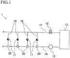
- a drain recovery system 1 of the present embodiment heats a target object by steam, and recovers drain generated by such heating.
- the drain recovery system 1 includes a steam supply pipe 11, a steam using instrument 13, a drain recovery pipe 14, multiple drain discharge pipes 16, and silencers 20 according to the claims of the present application.
- the steam supply pipe 11 is connected to the steam using instrument 13.
- the steam supply pipe 11 is, for example, connected to boiler equipment (not shown), and the steam generated by the boiler equipment is supplied to the steam using instrument 13.
- a pressure reduction valve 12 configured to adjust a steam pressure is provided at the steam supply pipe 11.
- the steam using instrument 13 is, for example, a heat exchanger, and condenses the steam supplied from the steam supply pipe 11 by heat radiation of the steam to the target object to heat the target object.
- the steam is condensed into the drain (steam condensate). That is, in the steam using instrument 13, latent heat of condensation of the steam is provided to the target object, and the target object is heated with the latent heat.
- the drain recovery pipe 14 is connected to the steam using instrument 13.
- the drain generated due to condensation of the steam in the steam using instrument 13 is recovered.
- a liquid pumping device 15 is provided at the drain recovery pipe 14.
- the liquid pumping device 15 is a pump configured to pump the drain generated in the steam using instrument 13 to a downstream side through the drain recovery pipe 14.
- the drain of the steam using instrument 13 flows into the liquid pumping device 15 through the drain recovery pipe 14, and is temporarily stored in the liquid pumping device 15.
- high-pressure operating gas is introduced into the liquid pumping device 15, and the stored drain is pumped to the downstream side by the pressure of the operating gas.
- the drain When the drain is pumped, the drain flows into the liquid pumping device 15 from the steam using instrument 13 again, and is stored in the liquid pumping device 15. In this manner, inflow of the drain and pumping (discharging) of the drain are alternately performed in the liquid pumping device 15.
- the multiple drain discharge pipes 16 are connected to between the steam supply pipe 11 and the drain recovery pipe 14. Specifically, upstream ends of the drain discharge pipes 16 are connected to the steam supply pipe 11, and downstream ends of the drain discharge pipes 16 are connected to the drain recovery pipe 14 through the silencers 20.
- the multiple drain discharge pipes 16 are provided at intervals (e.g., 20 to 30 m).
- the drain discharge pipe 16 is for causing the drain generated in the steam supply pipe 11 to flow into the drain recovery pipe 14. That is, part of the steam might be condensed into the drain in the steam supply pipe 11 in some cases, and such drain is recovered by the drain recovery pipe 14 through the drain discharge pipes 16 and the silencers 20.
- a steam trap 17 is provided in the middle of each drain discharge pipe 16.
- the drain generated in the steam supply pipe 11 flows into the steam traps 17 through the drain discharge pipes 16.
- the steam trap 17 is for automatically discharging only the inflow drain to the downstream side by an upstream-downstream pressure difference (a difference between a pressure on an upstream side and a pressure on the downstream side). Note that the drain mixed with the steam actually flows into the steam trap 15. In this manner, the drain generated in the steam supply pipe 11 joins, at the drain recovery pipe 14, the drain generated in the steam using instrument 13, and then, is pumped to the downstream side.
- the drain recovery pipe 14 is positioned below the steam supply pipe 11, and the drain discharge pipes 16 extend up and down and are connected to an upper portion of the drain recovery pipe 14.
- Each silencer 20 is provided at a connection portion between the drain recovery pipe 14 and the drain discharge pipe 16.
- the silencer 20 is for causing the steam to contact the drain in the silencer 20.
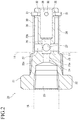
- the silencer 20 includes a main body 21 and a porous member 30.
- the left side is the upstream side
- the right side is the downstream side.
- the main body 21 has a head portion 22 and a shaft portion 23.
- the head portion 22 is formed in a flat substantially-hexagonal columnar shape.
- the shaft portion 23 is formed continuously to the downstream side of the head portion 22, and extends in an upstream-to-downstream direction.
- the shaft portion 23 is formed in a circular columnar shape concentric with the head portion 22.
- a thread portion 23a to be screwed with the drain recovery pipe 14 is formed at an outer peripheral surface of the shaft portion 23 on the upstream side.
- the thread portion 23a of the shaft portion 23 is screwed with the drain recovery pipe 14, and accordingly, the main body 21 is connected to the drain recovery pipe 14.
- a downstream portion of the shaft portion 23 with respect to the thread portion 23a is formed as a submerged portion 23b.
- the submerged portion 23b is a portion submerged in the drain flowing in the drain recovery pipe 14 when the main body 21 is connected to the drain recovery pipe 14.
- a flow path 24 for the drain and the steam is formed at the main body 21.
- the flow path 24 has an inlet port 25, a mixing portion 26, communication paths 27, and outlet ports 28.
- the inlet port 25 opens at an upstream side surface of the head portion 22, and extends in an axial direction (i.e., the upstream-to-downstream direction) of the shaft portion 23.
- the inlet port 25 is formed across the head portion 22 and the shaft portion 23. That is, the inlet port 25 is provided at a portion of the main body 21 other than the submerged portion 23b.
- the drain discharge pipe 16 is connected to the inlet port 25.
- a nozzle portion 25a configured to spray the steam to the mixing portion 26 is provided at the inlet port 25.
- the inner diameter of the nozzle portion 25a is smaller than those of other portions.
- the mixing portion 26, the communication paths 27, and the outlet ports 28 are provided at the submerged portion 23b of the shaft portion 23.
- the mixing portion 26 is provided at the center of the submerged portion 23b in a radial direction thereof, and is formed in a circular columnar shape concentric with the shaft portion 23 (the submerged portion 23b).
- the mixing portion 26 communicates with the nozzle portion 25a of the inlet port 25.
- the outlet ports 28 open at an outer peripheral surface of the submerged portion 23b, and the multiple (four in the present embodiment) outlet ports 28 are provided in a circumferential direction of the submerged portion 23b.
- the outlet port 28 is formed in an elongated substantially-rectangular shape extending in the axial direction of the shaft portion 23 (the submerged portion 23b). End portions (right and left end portions in FIG. 3 ) of the outlet port 28 in an axial direction thereof are formed in an arc shape.
- the length of the outlet port 28 in the axial direction thereof is longer than the length of the mixing portion 26 in an axial
- the communication path 27 is for causing the mixing portion 26 and the outlet port 28 to communicate with each other.
- the communication paths 27 extend from the mixing portion 26 in the radial direction of the submerged portion 23b, and are connected to the outlet ports 28.
- the communication paths 27 are connected to upstream end portions of the outlet ports 28 as the end portions of the outlet ports 28 in the axial direction thereof.
- a communication path 29 causing the mixing portion 26 and the outside to communicate with each other is formed at the submerged portion 23b.
- the communication path 29 is a linear flow path extending in the axial direction of the shaft portion 23, and is provided at the center of the submerged portion 23b in the radial direction thereof. That is, the communication path 29 extends from the mixing portion 26 in a downstream direction, and opens at a downstream end surface of the submerged portion 23b (the shaft portion 23).
- the communication path 29 has a slightly-larger inner diameter than that of the mixing portion 26.
- the submerged portion 23b is submerged in the drain of the drain recovery pipe 14, and therefore, through the outlet ports 28, the drain of the drain recovery pipe 14 flows into the mixing portion 26, the communication paths 27, the outlet ports 28, and the communication path 29 provided at the submerged portion 23b. Moreover, the drain of the drain recovery pipe 14 directly flows into the communication path 29.
- the mixing portion 26, the communication paths 27, the outlet ports 28, and the communication path 29 are drain present portions where the drain of the drain recovery pipe 14 is present.
- the drain present portion is a portion where the steam having flowed in through the inlet port 25 contacts the drain of the drain recovery pipe 14.
- the porous member 30 is formed in a cylindrical shape, and is provided at the outer periphery of the submerged portion 23b of the shaft portion 23.
- the porous member 30 covers the outlet ports 28.
- the porous member 30 allows the drain and the steam to flow out of the outlet ports 28.
- the porous member 30 allows external drain, i.e., the drain of the drain recovery pipe 14, to flow into the outlet ports 28.
- Pins 31 configured to prevent detachment of the porous member 30 from the submerged portion 23b are provided at the submerged portion 23b.
- the multiple (four in the present embodiment) pins 31 are provided at the outer periphery of the submerged portion 23b, and are press-fitted in insertion holes 32 formed at the outer peripheral surface of the submerged portion 23b.
- the porous member 30 is a member having many small holes allowing circulation of the drain and the steam.
- a metal mesh, punching metal, expanded metal, or a thin wire sintered body is used as the porous member 30.
- High-temperature drain discharged from the steam trap 17 flows in through the inlet port 25, and is mixed with low-temperature drain of the drain recovery pipe 14 at the mixing portion 26.
- the drain mixture flows into the outlet ports 28 through the communication paths 27, and flows out to the drain recovery pipe 14 through the porous member 30. In this manner, the drain generated in the steam supply pipe 11 is recovered by the drain recovery pipe 14.
- part of the drain discharged from the steam trap 17 might be re-evaporated into steam (flash steam). This is because the drain flowing into the steam trap 17 from the steam supply pipe 11 is at high temperature and a pressure drop is caused due to discharging of such high-temperature drain from the steam trap 17.
- the re-evaporated steam flows into the silencer 20.
- the steam having flowed into the inlet port 25 is sprayed from the nozzle portion 25a to the mixing portion 26.
- the sprayed steam comes into contact with the low-temperature drain present in the mixing portion 26, and then, is condensed.
- the steam is dispersively sprayed from the nozzle portion 25a.
- the drain generated by steam condensation flows into the outlet ports 28 through the communication paths 27, and flows out to the drain recovery pipe 14 through the porous member 30.
- the steam of the mixing portion 26 flows into the multiple outlet ports 28, and therefore, is dispersed and flows into the outlet ports 28.
- the amount of steam in each outlet port 28 decreases, and therefore, the steam condensation effect is more accelerated.
- the total flow path cross-sectional area of the multiple communication paths 27 is larger than the flow path cross-sectional area of the communication path 29.
- the steam is finely dispersed by the silencer 20, and flows into the drain recovery pipe 14.
- the great steam mass (space) is less formed in the drain recovery pipe 14. Consequently, the vacuum space caused due to rapid steam condensation is small.
- occurrence of great water hammer leading to noise and pipe damage is reduced. That is, the magnitude of water hammer decreases.
- the silencer 20 of the above-described embodiment includes the main body 21 provided with the flow path 24 having the steam inlet port 25 and the outlet ports 28.
- the main body 21 has the submerged portion 23b configured such that the outlet ports 28 are submerged in the drain and the steam contacts, in the flow path 24, the present drain having flowed in through the outlet ports 28.
- the silencer 20 includes the porous member 30 covering the outlet ports 28.
- the steam comes into contact with the drain in the flow path 24 provided at the submerged portion 23b, and therefore, can be condensed.
- the steam decreases.
- such steam can be finely dispersed by the porous member 30.
- the steam can dispersively flow out to the drain recovery pipe 14 in which the low-temperature drain flows.
- formation of the great steam mass (space) in the drain recovery pipe 14 can be reduced.
- occurrence of the water hammer due to rapid condensation of the steam mass can be reduced, or the magnitude of water hammer can be decreased. Consequently, noise and pipe damage due to the water hammer can be reduced.
- the multiple outlet ports 28 are provided at the submerged portion 23b.
- the flow path 24 has the mixing portion 26 and the multiple communication paths 27.
- the mixing portion 26 is provided at the submerged portion 23b, and communicates with the inlet port 25. In the mixing portion 26, the steam is mixed with the drain.
- the communication paths 27 are provided at the submerged portion 23b, and cause the mixing portion 26 and the multiple outlet ports 28 to communicate with each other.
- the steam having flowed into the mixing portion 26 through the inlet port 25 flows into the multiple outlet ports 28 through the multiple communication paths 27.
- the steam can dispersively flow into the outlet ports 28 from the mixing portion 26. Consequently, the amount of steam in each outlet port 28 decreases, and therefore, the steam condensation effect can be accelerated.
- the amount of steam flowing out to the drain recovery pipe 14 from the silencer 20 can be reduced.
- the submerged portion 23b is formed in a circular columnar shape.
- the multiple outlet ports 28 are arranged in the circumferential direction of the submerged portion 23b, and opens at the outer peripheral surface of the submerged portion 23b. According to this configuration, the steam can evenly contact, in the outlet ports 28, the low-temperature drain present outside the submerged portion 23b. Thus, the steam condensation effect can be accelerated.
- the outlet ports 28 are formed in an elongated shape extending in the axial direction of the submerged portion 23b.
- the opening area of the outlet ports 28 at the circular columnar submerged portion 23b can be earned.
- the mixing portion 26 is provided at the center of the submerged portion 23b in the radial direction thereof, and the communication paths 27 are connected to the mixing portion 26 and the end portions of the outlet ports 28 in the axial direction thereof. According to this configuration, the steam flow path length of the submerged portion 23b can be earned. Thus, the region where the steam and the low-temperature drain contact each other can be increased, and therefore, the steam condensation effect can be accelerated.
- the inlet port 25 is provided at a portion of the main body 21 other than the submerged portion 23b, and has the nozzle portion 25a configured to spray the steam to the mixing portion 26.
- the steam is dispersively sprayed by the nozzle portion 25a.
- the area of contact between the steam and the low-temperature drain in the mixing portion 26 can be increased, and the steam condensation effect can be accelerated.
- the technique disclosed in the present application may have the following configurations in the above-described embodiment.
- the single outlet port 28 and the single communication path 27 may be provided.
- nozzle portion 25a may be omitted from the inlet port 25.
- the technique disclosed in the present application is useful for a silencer configured to cause steam to contact drain.
Landscapes
- Engineering & Computer Science (AREA)
- General Engineering & Computer Science (AREA)
- Mechanical Engineering (AREA)
- Physics & Mathematics (AREA)
- Water Supply & Treatment (AREA)
- Thermal Sciences (AREA)
- Chemical & Material Sciences (AREA)
- Aviation & Aerospace Engineering (AREA)
- Combustion & Propulsion (AREA)
- Fluid Mechanics (AREA)
- Acoustics & Sound (AREA)
- Multimedia (AREA)
- Pipe Accessories (AREA)
- Exhaust Silencers (AREA)
- Compressor (AREA)
Applications Claiming Priority (2)
| Application Number | Priority Date | Filing Date | Title |
|---|---|---|---|
| JP2017095490 | 2017-05-12 | ||
| PCT/JP2018/016960 WO2018207637A1 (ja) | 2017-05-12 | 2018-04-26 | サイレンサ |
Publications (3)
| Publication Number | Publication Date |
|---|---|
| EP3623683A1 true EP3623683A1 (de) | 2020-03-18 |
| EP3623683A4 EP3623683A4 (de) | 2020-06-17 |
| EP3623683B1 EP3623683B1 (de) | 2021-09-29 |
Family
ID=64105588
Family Applications (1)
| Application Number | Title | Priority Date | Filing Date |
|---|---|---|---|
| EP18797908.3A Active EP3623683B1 (de) | 2017-05-12 | 2018-04-26 | Schalldämpfer |
Country Status (7)
| Country | Link |
|---|---|
| US (1) | US11315537B2 (de) |
| EP (1) | EP3623683B1 (de) |
| JP (1) | JP6531223B2 (de) |
| KR (1) | KR102277955B1 (de) |
| CN (1) | CN110603402B (de) |
| MY (1) | MY196785A (de) |
| WO (1) | WO2018207637A1 (de) |
Families Citing this family (1)
| Publication number | Priority date | Publication date | Assignee | Title |
|---|---|---|---|---|
| JP7458072B2 (ja) * | 2020-09-10 | 2024-03-29 | 株式会社テイエルブイ | サイレンサ |
Family Cites Families (21)
| Publication number | Priority date | Publication date | Assignee | Title |
|---|---|---|---|---|
| GB385599A (en) * | 1930-03-26 | 1932-12-29 | Harburger Metallgiesserei Und | Improvements in or relating to devices for drawing off water from containers or pipes which are under pressure |
| JPS5527241B2 (de) | 1973-09-20 | 1980-07-19 | ||
| JPS5075121U (de) * | 1973-11-13 | 1975-07-01 | ||
| JPS55168793U (de) * | 1979-05-24 | 1980-12-04 | ||
| JPS6222721Y2 (de) * | 1981-04-01 | 1987-06-10 | ||
| JPH04126098U (ja) * | 1991-05-01 | 1992-11-17 | 三菱重工業株式会社 | ドレントラツプ |
| US5304748A (en) * | 1992-01-06 | 1994-04-19 | Destec Engineering, Inc. | Methods and apparatuses for muffling power plant steam exhaust |
| JPH0760089A (ja) * | 1993-08-20 | 1995-03-07 | Yunisun:Kk | 蒸気と水の混合器 |
| CN2229818Y (zh) * | 1995-08-24 | 1996-06-26 | 付汉权 | 车用消烟消声防火防爆装置 |
| JP2000304204A (ja) * | 1999-04-23 | 2000-11-02 | Babcock Hitachi Kk | ボイラのドレン排出装置 |
| JP4115820B2 (ja) * | 2002-12-13 | 2008-07-09 | 株式会社テイエルブイ | 液体圧送装置 |
| JP4357894B2 (ja) * | 2003-07-15 | 2009-11-04 | 株式会社テイエルブイ | 液体圧送装置 |
| CN2784589Y (zh) * | 2005-03-03 | 2006-05-31 | 李志强 | 蒸汽、空气消音器 |
| KR101097773B1 (ko) * | 2010-06-29 | 2011-12-22 | 유춘희 | 전자 전극봉식 가습기 |
| US9404365B2 (en) * | 2013-02-13 | 2016-08-02 | Taylor's Industrial Coatings, Inc. | Steam diffusing apparatus and related methods |
| KR101339668B1 (ko) * | 2013-07-22 | 2013-12-10 | 황장선 | 응축수 회수 장치 |
| GB2530282B (en) * | 2014-09-17 | 2020-09-23 | Spirax Sarco Ltd | A Condensate drain |
| CN204704538U (zh) * | 2015-06-23 | 2015-10-14 | 胡晟玮 | 用于石油炼化工艺的冷凝回水水击消除器 |
| JP6899255B2 (ja) * | 2017-05-12 | 2021-07-07 | 株式会社テイエルブイ | ドレン回収システム及び配管継手 |
| JP6894788B2 (ja) * | 2017-07-20 | 2021-06-30 | 株式会社テイエルブイ | サイレンサ |
| CN108895423B (zh) * | 2018-07-11 | 2019-08-27 | 河南中烟工业有限责任公司 | 一种卷烟厂用蒸汽供应系统 |
-
2018
- 2018-04-26 CN CN201880029922.1A patent/CN110603402B/zh active Active
- 2018-04-26 EP EP18797908.3A patent/EP3623683B1/de active Active
- 2018-04-26 WO PCT/JP2018/016960 patent/WO2018207637A1/ja not_active Ceased
- 2018-04-26 JP JP2018537885A patent/JP6531223B2/ja active Active
- 2018-04-26 MY MYPI2019006541A patent/MY196785A/en unknown
- 2018-04-26 KR KR1020197033752A patent/KR102277955B1/ko active Active
-
2019
- 2019-10-30 US US16/668,013 patent/US11315537B2/en active Active
Also Published As
| Publication number | Publication date |
|---|---|
| EP3623683A4 (de) | 2020-06-17 |
| JPWO2018207637A1 (ja) | 2019-06-27 |
| US20200066244A1 (en) | 2020-02-27 |
| KR102277955B1 (ko) | 2021-07-16 |
| CN110603402B (zh) | 2021-05-28 |
| WO2018207637A1 (ja) | 2018-11-15 |
| MY196785A (en) | 2023-05-03 |
| JP6531223B2 (ja) | 2019-06-12 |
| KR20190137887A (ko) | 2019-12-11 |
| EP3623683B1 (de) | 2021-09-29 |
| US11315537B2 (en) | 2022-04-26 |
| CN110603402A (zh) | 2019-12-20 |
Similar Documents
| Publication | Publication Date | Title |
|---|---|---|
| JP5698895B2 (ja) | タービン用の排気フードを組立てるための方法及びシステム | |
| CN107923259B (zh) | 用于附接通过空气射流冷却涡轮机的外壳的歧管的装置 | |
| JP2017530291A (ja) | タービンブレード | |
| KR20190086542A (ko) | 증기 터빈 | |
| US11315537B2 (en) | Silencer | |
| JP7273607B2 (ja) | サイレンサ | |
| JP6894788B2 (ja) | サイレンサ | |
| EP2857774A1 (de) | Heisswassererzeuger | |
| WO2018135212A1 (ja) | 蒸気タービン | |
| JP4177694B2 (ja) | 蒸気弁 | |
| CN107842397A (zh) | 涡轮机进口、涡轮机系统以及改型涡轮机的蒸汽进口的方法 | |
| JP6899255B2 (ja) | ドレン回収システム及び配管継手 | |
| JP2005226640A (ja) | エンジンの燃焼室冷却システム | |
| JP2002263460A (ja) | 静音型ミキサー | |
| JP7458072B2 (ja) | サイレンサ | |
| US9422831B2 (en) | Condenser | |
| US20130174553A1 (en) | Diffuser having fluidic actuation | |
| JP6567365B2 (ja) | タービン排気装置およびタービン | |
| JP2014001647A (ja) | 蒸気タービンのドレン排出装置 | |
| KR20210098152A (ko) | 복수기 시스템 | |
| KR102004853B1 (ko) | 스팀분배장치가 설치된 스팀응축장치 | |
| JP2018194185A (ja) | ドレン回収システム | |
| KR20220135553A (ko) | 응축수 배관의 수격 방지 장치 | |
| WO2008015431A2 (en) | Condensate traps | |
| JP2018194186A (ja) | ドレン回収システム及び配管継手 |
Legal Events
| Date | Code | Title | Description |
|---|---|---|---|
| STAA | Information on the status of an ep patent application or granted ep patent |
Free format text: STATUS: THE INTERNATIONAL PUBLICATION HAS BEEN MADE |
|
| PUAI | Public reference made under article 153(3) epc to a published international application that has entered the european phase |
Free format text: ORIGINAL CODE: 0009012 |
|
| STAA | Information on the status of an ep patent application or granted ep patent |
Free format text: STATUS: THE APPLICATION HAS BEEN PUBLISHED |
|
| STAA | Information on the status of an ep patent application or granted ep patent |
Free format text: STATUS: REQUEST FOR EXAMINATION WAS MADE |
|
| 17P | Request for examination filed |
Effective date: 20191209 |
|
| AK | Designated contracting states |
Kind code of ref document: A1 Designated state(s): AL AT BE BG CH CY CZ DE DK EE ES FI FR GB GR HR HU IE IS IT LI LT LU LV MC MK MT NL NO PL PT RO RS SE SI SK SM TR |
|
| AX | Request for extension of the european patent |
Extension state: BA ME |
|
| A4 | Supplementary search report drawn up and despatched |
Effective date: 20200515 |
|
| RIC1 | Information provided on ipc code assigned before grant |
Ipc: F16L 55/045 20060101AFI20200511BHEP Ipc: F28B 9/00 20060101ALI20200511BHEP Ipc: F22D 11/06 20060101ALI20200511BHEP Ipc: F16T 1/38 20060101ALI20200511BHEP |
|
| DAV | Request for validation of the european patent (deleted) | ||
| DAX | Request for extension of the european patent (deleted) | ||
| GRAP | Despatch of communication of intention to grant a patent |
Free format text: ORIGINAL CODE: EPIDOSNIGR1 |
|
| STAA | Information on the status of an ep patent application or granted ep patent |
Free format text: STATUS: GRANT OF PATENT IS INTENDED |
|
| INTG | Intention to grant announced |
Effective date: 20210519 |
|
| GRAS | Grant fee paid |
Free format text: ORIGINAL CODE: EPIDOSNIGR3 |
|
| GRAA | (expected) grant |
Free format text: ORIGINAL CODE: 0009210 |
|
| STAA | Information on the status of an ep patent application or granted ep patent |
Free format text: STATUS: THE PATENT HAS BEEN GRANTED |
|
| AK | Designated contracting states |
Kind code of ref document: B1 Designated state(s): AL AT BE BG CH CY CZ DE DK EE ES FI FR GB GR HR HU IE IS IT LI LT LU LV MC MK MT NL NO PL PT RO RS SE SI SK SM TR |
|
| REG | Reference to a national code |
Ref country code: GB Ref legal event code: FG4D |
|
| REG | Reference to a national code |
Ref country code: DE Ref legal event code: R096 Ref document number: 602018024388 Country of ref document: DE |
|
| REG | Reference to a national code |
Ref country code: CH Ref legal event code: EP Ref country code: AT Ref legal event code: REF Ref document number: 1434501 Country of ref document: AT Kind code of ref document: T Effective date: 20211015 |
|
| REG | Reference to a national code |
Ref country code: IE Ref legal event code: FG4D |
|
| REG | Reference to a national code |
Ref country code: NL Ref legal event code: FP |
|
| REG | Reference to a national code |
Ref country code: LT Ref legal event code: MG9D |
|
| PG25 | Lapsed in a contracting state [announced via postgrant information from national office to epo] |
Ref country code: HR Free format text: LAPSE BECAUSE OF FAILURE TO SUBMIT A TRANSLATION OF THE DESCRIPTION OR TO PAY THE FEE WITHIN THE PRESCRIBED TIME-LIMIT Effective date: 20210929 Ref country code: FI Free format text: LAPSE BECAUSE OF FAILURE TO SUBMIT A TRANSLATION OF THE DESCRIPTION OR TO PAY THE FEE WITHIN THE PRESCRIBED TIME-LIMIT Effective date: 20210929 Ref country code: SE Free format text: LAPSE BECAUSE OF FAILURE TO SUBMIT A TRANSLATION OF THE DESCRIPTION OR TO PAY THE FEE WITHIN THE PRESCRIBED TIME-LIMIT Effective date: 20210929 Ref country code: RS Free format text: LAPSE BECAUSE OF FAILURE TO SUBMIT A TRANSLATION OF THE DESCRIPTION OR TO PAY THE FEE WITHIN THE PRESCRIBED TIME-LIMIT Effective date: 20210929 Ref country code: LT Free format text: LAPSE BECAUSE OF FAILURE TO SUBMIT A TRANSLATION OF THE DESCRIPTION OR TO PAY THE FEE WITHIN THE PRESCRIBED TIME-LIMIT Effective date: 20210929 Ref country code: BG Free format text: LAPSE BECAUSE OF FAILURE TO SUBMIT A TRANSLATION OF THE DESCRIPTION OR TO PAY THE FEE WITHIN THE PRESCRIBED TIME-LIMIT Effective date: 20211229 Ref country code: NO Free format text: LAPSE BECAUSE OF FAILURE TO SUBMIT A TRANSLATION OF THE DESCRIPTION OR TO PAY THE FEE WITHIN THE PRESCRIBED TIME-LIMIT Effective date: 20211229 |
|
| REG | Reference to a national code |
Ref country code: AT Ref legal event code: MK05 Ref document number: 1434501 Country of ref document: AT Kind code of ref document: T Effective date: 20210929 |
|
| PG25 | Lapsed in a contracting state [announced via postgrant information from national office to epo] |
Ref country code: LV Free format text: LAPSE BECAUSE OF FAILURE TO SUBMIT A TRANSLATION OF THE DESCRIPTION OR TO PAY THE FEE WITHIN THE PRESCRIBED TIME-LIMIT Effective date: 20210929 Ref country code: GR Free format text: LAPSE BECAUSE OF FAILURE TO SUBMIT A TRANSLATION OF THE DESCRIPTION OR TO PAY THE FEE WITHIN THE PRESCRIBED TIME-LIMIT Effective date: 20211230 |
|
| PG25 | Lapsed in a contracting state [announced via postgrant information from national office to epo] |
Ref country code: AT Free format text: LAPSE BECAUSE OF FAILURE TO SUBMIT A TRANSLATION OF THE DESCRIPTION OR TO PAY THE FEE WITHIN THE PRESCRIBED TIME-LIMIT Effective date: 20210929 |
|
| PG25 | Lapsed in a contracting state [announced via postgrant information from national office to epo] |
Ref country code: IS Free format text: LAPSE BECAUSE OF FAILURE TO SUBMIT A TRANSLATION OF THE DESCRIPTION OR TO PAY THE FEE WITHIN THE PRESCRIBED TIME-LIMIT Effective date: 20220129 Ref country code: SK Free format text: LAPSE BECAUSE OF FAILURE TO SUBMIT A TRANSLATION OF THE DESCRIPTION OR TO PAY THE FEE WITHIN THE PRESCRIBED TIME-LIMIT Effective date: 20210929 Ref country code: RO Free format text: LAPSE BECAUSE OF FAILURE TO SUBMIT A TRANSLATION OF THE DESCRIPTION OR TO PAY THE FEE WITHIN THE PRESCRIBED TIME-LIMIT Effective date: 20210929 Ref country code: PT Free format text: LAPSE BECAUSE OF FAILURE TO SUBMIT A TRANSLATION OF THE DESCRIPTION OR TO PAY THE FEE WITHIN THE PRESCRIBED TIME-LIMIT Effective date: 20220131 Ref country code: PL Free format text: LAPSE BECAUSE OF FAILURE TO SUBMIT A TRANSLATION OF THE DESCRIPTION OR TO PAY THE FEE WITHIN THE PRESCRIBED TIME-LIMIT Effective date: 20210929 Ref country code: ES Free format text: LAPSE BECAUSE OF FAILURE TO SUBMIT A TRANSLATION OF THE DESCRIPTION OR TO PAY THE FEE WITHIN THE PRESCRIBED TIME-LIMIT Effective date: 20210929 Ref country code: EE Free format text: LAPSE BECAUSE OF FAILURE TO SUBMIT A TRANSLATION OF THE DESCRIPTION OR TO PAY THE FEE WITHIN THE PRESCRIBED TIME-LIMIT Effective date: 20210929 Ref country code: CZ Free format text: LAPSE BECAUSE OF FAILURE TO SUBMIT A TRANSLATION OF THE DESCRIPTION OR TO PAY THE FEE WITHIN THE PRESCRIBED TIME-LIMIT Effective date: 20210929 Ref country code: AL Free format text: LAPSE BECAUSE OF FAILURE TO SUBMIT A TRANSLATION OF THE DESCRIPTION OR TO PAY THE FEE WITHIN THE PRESCRIBED TIME-LIMIT Effective date: 20210929 |
|
| REG | Reference to a national code |
Ref country code: DE Ref legal event code: R097 Ref document number: 602018024388 Country of ref document: DE |
|
| PG25 | Lapsed in a contracting state [announced via postgrant information from national office to epo] |
Ref country code: DK Free format text: LAPSE BECAUSE OF FAILURE TO SUBMIT A TRANSLATION OF THE DESCRIPTION OR TO PAY THE FEE WITHIN THE PRESCRIBED TIME-LIMIT Effective date: 20210929 |
|
| PLBE | No opposition filed within time limit |
Free format text: ORIGINAL CODE: 0009261 |
|
| STAA | Information on the status of an ep patent application or granted ep patent |
Free format text: STATUS: NO OPPOSITION FILED WITHIN TIME LIMIT |
|
| 26N | No opposition filed |
Effective date: 20220630 |
|
| PG25 | Lapsed in a contracting state [announced via postgrant information from national office to epo] |
Ref country code: SI Free format text: LAPSE BECAUSE OF FAILURE TO SUBMIT A TRANSLATION OF THE DESCRIPTION OR TO PAY THE FEE WITHIN THE PRESCRIBED TIME-LIMIT Effective date: 20210929 |
|
| REG | Reference to a national code |
Ref country code: BE Ref legal event code: MM Effective date: 20220430 |
|
| PG25 | Lapsed in a contracting state [announced via postgrant information from national office to epo] |
Ref country code: MC Free format text: LAPSE BECAUSE OF FAILURE TO SUBMIT A TRANSLATION OF THE DESCRIPTION OR TO PAY THE FEE WITHIN THE PRESCRIBED TIME-LIMIT Effective date: 20210929 Ref country code: LU Free format text: LAPSE BECAUSE OF NON-PAYMENT OF DUE FEES Effective date: 20220426 |
|
| PG25 | Lapsed in a contracting state [announced via postgrant information from national office to epo] |
Ref country code: BE Free format text: LAPSE BECAUSE OF NON-PAYMENT OF DUE FEES Effective date: 20220430 |
|
| PG25 | Lapsed in a contracting state [announced via postgrant information from national office to epo] |
Ref country code: IE Free format text: LAPSE BECAUSE OF NON-PAYMENT OF DUE FEES Effective date: 20220426 |
|
| PG25 | Lapsed in a contracting state [announced via postgrant information from national office to epo] |
Ref country code: SM Free format text: LAPSE BECAUSE OF FAILURE TO SUBMIT A TRANSLATION OF THE DESCRIPTION OR TO PAY THE FEE WITHIN THE PRESCRIBED TIME-LIMIT Effective date: 20210929 Ref country code: MK Free format text: LAPSE BECAUSE OF FAILURE TO SUBMIT A TRANSLATION OF THE DESCRIPTION OR TO PAY THE FEE WITHIN THE PRESCRIBED TIME-LIMIT Effective date: 20210929 Ref country code: CY Free format text: LAPSE BECAUSE OF FAILURE TO SUBMIT A TRANSLATION OF THE DESCRIPTION OR TO PAY THE FEE WITHIN THE PRESCRIBED TIME-LIMIT Effective date: 20210929 |
|
| PG25 | Lapsed in a contracting state [announced via postgrant information from national office to epo] |
Ref country code: HU Free format text: LAPSE BECAUSE OF FAILURE TO SUBMIT A TRANSLATION OF THE DESCRIPTION OR TO PAY THE FEE WITHIN THE PRESCRIBED TIME-LIMIT; INVALID AB INITIO Effective date: 20180426 |
|
| PG25 | Lapsed in a contracting state [announced via postgrant information from national office to epo] |
Ref country code: MT Free format text: LAPSE BECAUSE OF FAILURE TO SUBMIT A TRANSLATION OF THE DESCRIPTION OR TO PAY THE FEE WITHIN THE PRESCRIBED TIME-LIMIT Effective date: 20210929 |
|
| PGFP | Annual fee paid to national office [announced via postgrant information from national office to epo] |
Ref country code: NL Payment date: 20250418 Year of fee payment: 8 |
|
| PGFP | Annual fee paid to national office [announced via postgrant information from national office to epo] |
Ref country code: DE Payment date: 20250422 Year of fee payment: 8 |
|
| PGFP | Annual fee paid to national office [announced via postgrant information from national office to epo] |
Ref country code: GB Payment date: 20250423 Year of fee payment: 8 |
|
| PGFP | Annual fee paid to national office [announced via postgrant information from national office to epo] |
Ref country code: IT Payment date: 20250424 Year of fee payment: 8 |
|
| PGFP | Annual fee paid to national office [announced via postgrant information from national office to epo] |
Ref country code: FR Payment date: 20250425 Year of fee payment: 8 |
|
| PGFP | Annual fee paid to national office [announced via postgrant information from national office to epo] |
Ref country code: CH Payment date: 20250501 Year of fee payment: 8 |
|
| PGFP | Annual fee paid to national office [announced via postgrant information from national office to epo] |
Ref country code: TR Payment date: 20250421 Year of fee payment: 8 |