EP3623702B1 - Feststofffeuerstellenofenrohr - Google Patents
Feststofffeuerstellenofenrohr Download PDFInfo
- Publication number
- EP3623702B1 EP3623702B1 EP19190144.6A EP19190144A EP3623702B1 EP 3623702 B1 EP3623702 B1 EP 3623702B1 EP 19190144 A EP19190144 A EP 19190144A EP 3623702 B1 EP3623702 B1 EP 3623702B1
- Authority
- EP
- European Patent Office
- Prior art keywords
- solid fuel
- pipe
- connection section
- fuel furnace
- cooling
- Prior art date
- Legal status (The legal status is an assumption and is not a legal conclusion. Google has not performed a legal analysis and makes no representation as to the accuracy of the status listed.)
- Active
Links
Images


Classifications
-
- F—MECHANICAL ENGINEERING; LIGHTING; HEATING; WEAPONS; BLASTING
- F23—COMBUSTION APPARATUS; COMBUSTION PROCESSES
- F23J—REMOVAL OR TREATMENT OF COMBUSTION PRODUCTS OR COMBUSTION RESIDUES; FLUES
- F23J11/00—Devices for conducting smoke or fumes, e.g. flues
-
- F—MECHANICAL ENGINEERING; LIGHTING; HEATING; WEAPONS; BLASTING
- F23—COMBUSTION APPARATUS; COMBUSTION PROCESSES
- F23J—REMOVAL OR TREATMENT OF COMBUSTION PRODUCTS OR COMBUSTION RESIDUES; FLUES
- F23J13/00—Fittings for chimneys or flues
- F23J13/02—Linings; Jackets; Casings
- F23J13/025—Linings; Jackets; Casings composed of concentric elements, e.g. double walled
-
- F—MECHANICAL ENGINEERING; LIGHTING; HEATING; WEAPONS; BLASTING
- F23—COMBUSTION APPARATUS; COMBUSTION PROCESSES
- F23J—REMOVAL OR TREATMENT OF COMBUSTION PRODUCTS OR COMBUSTION RESIDUES; FLUES
- F23J13/00—Fittings for chimneys or flues
- F23J13/04—Joints; Connections
-
- F—MECHANICAL ENGINEERING; LIGHTING; HEATING; WEAPONS; BLASTING
- F23—COMBUSTION APPARATUS; COMBUSTION PROCESSES
- F23J—REMOVAL OR TREATMENT OF COMBUSTION PRODUCTS OR COMBUSTION RESIDUES; FLUES
- F23J2213/00—Chimneys or flues
- F23J2213/20—Joints; Connections
- F23J2213/201—Joints; Connections between stack and branch pipes
-
- F—MECHANICAL ENGINEERING; LIGHTING; HEATING; WEAPONS; BLASTING
- F23—COMBUSTION APPARATUS; COMBUSTION PROCESSES
- F23J—REMOVAL OR TREATMENT OF COMBUSTION PRODUCTS OR COMBUSTION RESIDUES; FLUES
- F23J2213/00—Chimneys or flues
- F23J2213/20—Joints; Connections
- F23J2213/203—Joints; Connections between stack/duct and combustion apparatus
Definitions
- the invention relates to a solid fuel fireplace furnace tube, a solid fuel fireplace adapter piece, a cover plate and a solid fuel fireplace system.
- Solid fire place connection systems are already known from the prior art, these serve to connect a solid fire place, such as a wood-burning stove, to a chimney in such a way that the combustion gases from the fire place can get into the chimney.
- connection systems In order to achieve this connection to the fireplace and / or the chimney, connection systems have at least one stove pipe.
- such systems can also include adapter pieces in order to achieve the connection of the stove pipe to the chimney or the connection of the stove pipe to the fireplace.
- the problem with the already known solid fire place connection systems is that they can get very hot on the outside, so that, among other things, there is a high risk of injury to people.
- the U.S. 987,792 shows a heating and ventilation system which is designed in particular for use in school rooms, halls or similar rooms.
- a cooling pipe is arranged concentrically around the exhaust pipe of a window.
- the U.S. 886,391 relates to a ventilation system for rooms comprising a cylindrical drum which surrounds a pipe for a fireplace.
- the DE 87 03 869 U1 relates to a heating boiler which consists of a water-carrying housing in which the gas-carrying spaces and spaces opening into an exhaust gas outlet connection with a flue pipe on the exhaust side are arranged.
- a solid fuel furnace tube comprises a first connection section, an intermediate area, a second connection section, an exhaust pipe and a cooling tube, the intermediate area extending between the first and the second connection section, the first connection section being designed to be central and / or to be connected directly, wherein the second connection section is designed to be connected directly and / or indirectly to a chimney, wherein the exhaust pipe in the first connection section has an exhaust gas receiving opening which is designed to be connected to an exhaust gas outlet of a solid fuel hearth central and / or or to be directly connected, the exhaust pipe having an exhaust gas outlet opening in the second connection section, which is designed to be directly and / or indirectly connected to a chimney exhaust pipe, the cooling pipe having a first cooling opening in the first connection section ung and has a second cooling opening in the second connection section, the interior space enclosed by the cooling tube being fluidically connected to the environment through the first cooling opening and the second cooling opening, the cooling tube surrounding the exhaust pipe, at least in the intermediate area, in particular concentrically.
- the solid fuel furnace tube is generally used to connect a solid fuel furnace to a chimney in such a way that exhaust gases from the solid fuel furnace can get into the chimney.
- a solid fuel hearth is a hearth that is operated with solid fuels, such as coal, wood or pellets.
- the solid fuel hearth can in particular be a stove that can be found in the living rooms of individual houses.
- the chimney, with which the solid fuel hearth furnace pipe is directly and / or indirectly connected, can be that part of the building which serves to divert the exhaust gas from the solid fuel hearth into the surroundings / environment around the building. In other words, the solid-fuel hearth furnace pipe serves to direct the exhaust gases from a solid-fuel hearth into the chimney.
- the solid fuel furnace tube can be arranged horizontally at least in some areas in an installed state.
- the solid fuel furnace tube has a first connection section and a second connection section, with two connection sections between these two connection sections the intermediate area extends.
- the first connection section serves to be fixed and / or to be attached to the solid fuel hearth, especially in an installed state
- the second connection section serves to be connected directly and / or indirectly to the chimney, especially in an installed state.
- the solid fuel furnace tube has an exhaust pipe which has an exhaust gas intake opening in the first connection section and an exhaust gas outlet opening in the second connection section. The exhaust pipe therefore serves to fluidically guide the exhaust gases produced by the solid fuel fireplace from the first connection section to the second connection section.
- the exhaust gas outlet opening is fluidically connected to a chimney exhaust pipe and the exhaust gas receiving opening to an exhaust gas outlet of the fireplace.
- the exhaust pipe fluidly connects the exhaust gas intake opening to the exhaust gas outlet opening.
- Connecting / conducting fluidically can mean, among other things, that a fluid, in particular channel-like, can flow from the receiving opening to the outlet opening.
- the exhaust pipe is designed in such a way that its interior is fluidically connected only via an exhaust gas intake opening and an exhaust gas outlet opening, so that no exhaust gas can leave the exhaust pipe at other openings.
- the solid fuel furnace pipe also has a cooling pipe which has a first cooling opening in the first connection section and a second cooling opening in the second connection section, and these cooling openings are designed to allow a fluid to flow into or out of the interior space enclosed by the cooling pipe Environment can flow.
- this can mean that the interior space enclosed by the cooling tube is fluidically connected to the environment via the first cooling opening and the second cooling opening.
- the cooling tube is designed in such a way that the interior of the cooling tube is fluidly connected to the environment exclusively via the cooling openings.
- the cooling pipe does not serve to guide combustion air to the solid fuel hearth and / or to lead exhaust gases away from the solid fuel hearth.
- the environment is, in particular, the room air, in particular of an interior space that surrounds the solid fuel furnace tube.
- the cooling openings of the Cooling tube therefore in a single interior of a room.
- the cooling openings of the solid fuel furnace tube are expediently spaced a maximum of 1.2m, preferably a maximum of 1m, particularly preferably a maximum of 0.7m and particularly preferably a maximum of 0.6m, because the cooling openings of the cooling tube serve in particular exclusively to connect the interior of the cooling tube with the air flow of the to connect the surrounding interior of a building.
- the cooling pipe and the exhaust pipe are arranged in the solid fuel furnace pipe in such a way that the cooling pipe surrounds the exhaust pipe at least in the intermediate area.
- the cooling pipe surrounds the exhaust pipe in such a way that these two pipes are arranged concentrically to one another, at least in the intermediate region.
- the cooling pipe advantageously surrounds the exhaust pipe not only in the intermediate area, but also for the most part in the first connection section and / or in the second connection section.
- Surrounded in this context generally means that one tube surrounds or encases the other tube in the circumferential direction and / or in the longitudinal direction at least in some areas, preferably for the most part, particularly preferably completely.
- the interior of the cooling pipe is a gap, in particular an annular gap, the volume / cross section of which is delimited on the outside by the cooling pipe and on the inside by the exhaust pipe.
- surrounded can also mean that no fluid flow is possible from the interior of one pipe into the other pipe, and that one pipe is also encased by the other pipe, at least in some areas, preferably for the most part. Because the exhaust pipe is surrounded by the cooling pipe and the fluid flow occurring in the cooling pipe as a result of the heating, the outer skin of the cooling pipe is significantly cooler than the exhaust pipe. Thus it is not possible or only with difficulty for a person, at least in the intermediate area, to touch the hot exhaust pipe, but only the significantly cooler cooling pipe, so that the risk of injury can be significantly reduced by using the cooling pipe.
- the exhaust pipe advantageously extends in the first connection section along a first connection direction and / or wherein the exhaust pipe extends in the second connection section along a second connection direction.
- This straight-line configuration of the first connection section along a first connection direction and / or of the second connection section along a second connection direction can significantly simplify the assembly of the solid fuel furnace tube. In addition, this measure not only simplifies assembly, but also simplifies its manufacture, so that costs can be saved.
- the intermediate area is expediently curved and / or straight. This makes it easier to assemble the solid fuel furnace tube.
- the intermediate area is advantageously designed in such a way that it is curved by an angle of 80 ° to 100 °. In this way it can be achieved that the solid fuel furnace tube is already factory-adapted to most existing installation situations, so that costs can be saved in the final installation.
- the exhaust pipe preferably projects beyond the cooling pipe in the direction of the first connection direction and / or wherein the exhaust pipe in the second connection section projects beyond the cooling pipe in the direction of the second connection direction.
- assembly can be simplified because the protruding part of the cooling pipe can be used as a type of guide unit.
- protruding means that the exhaust pipe extends further in the respective connection direction in the respective connection section than the cooling pipe.
- the ratio of the protruding length in the first and / or in the second connection direction to the mean outer diameter of the exhaust pipe is preferably in a range from 0.55 to 0.75, because the applicant has surprisingly found that with such a ratio a particularly intuitive Assembly results for the fitter, so that costs can be saved during assembly.
- the exhaust pipe preferably has an inspection opening.
- This inspection opening enables the stove pipe to be easily cleaned and / or inspected.
- the inspection opening is arranged in the intermediate area, in particular in the curved part of the intermediate area.
- the inspection opening is advantageously designed in such a way that it enables access to the interior of the exhaust pipe.
- the inspection opening does not allow access to the interior of the cooling tube. In other words, this can mean that the interior of the exhaust pipe can be temporarily fluidly connected to the surroundings through the inspection opening, but not the interior of the cooling pipe.
- the inspection opening can expediently be closed by means of a closure element.
- the exhaust pipe is expediently configured conically in the first connection section and / or the exhaust pipe is configured conically in the second connection section.
- a particularly high sealing effect can be achieved in a simple manner.
- this measure can also mean that expensive sealing elements can be saved, so that a particularly cost-effective solid fuel furnace tube is achieved.
- the conical section of the exhaust pipe is designed in particular in such a way that it tapers or widens in the direction of the distal end of the first and / or the second connection section. In other words, this can mean that the cone - like an arrow - points away from or towards the intermediate area or the respective connection section.
- the slope of the cone is advantageously in a range from 0.05 ° to 5 °, in particular in the range from 0.1 to 3 ° and particularly preferably in the range from 0.5 ° to 2.5 °.
- a slope of the cone in the range of 0.05 ° to 5 °, a particularly high sealing effect can be achieved.
- the slope of the cone should be in a range of 0.1 ° to 3 °.
- the cone is particularly easy to manufacture if its slope is in the range between 0.5 ° to 3 °, so that a particularly inexpensive solid fuel furnace tube results.
- the cooling pipe expediently surrounds the exhaust pipe in the first connection section and / or in the second connection section at least in some areas, preferably for the most part, in particular concentrically. This can further reduce the risk of injury.
- the cooling pipe and / or the exhaust pipe preferably consists at least for the most part, in particular completely, of stainless steel or black plate. In this way, a particularly high temperature-resistant solid fuel furnace tube can be achieved.
- At least one support element preferably a plurality of support elements, in particular in the interior of the cooling pipe, is advantageously arranged between the exhaust pipe and the cooling pipe.
- the support element or elements are advantageously connected to the exhaust gas pipe and / or to the cooling pipe in a materially bonded manner, in particular by means of a weld seam.
- the support elements are arranged in the first connection section and / or in the second connection section.
- the support elements are preferably arranged uniformly in the circumferential direction and / or in the longitudinal direction.
- the circumferential direction is the circumferential direction around the longitudinal direction.
- the longitudinal direction is to be understood in particular as the connection direction from the first connection section to the second connection section, this connection direction not necessarily always having to be straight.
- the longitudinal direction can be the direction which corresponds to the mean flow direction in the cross section, in particular within the exhaust pipe, in the case of a flow from the first connection section to the second connection section.
- the ratio of the diameter of the exhaust pipe to the diameter of the cooling pipe is advantageously in a range from 0.5 to 0.95, preferably in a range from 0.6 to 0.85 and particularly preferably in a range from 0.7 to 0 ,8th.
- the relevant diameter is the inside diameter or the outside diameter of the respective pipe. In the case of a non-circular cross-section, the diameter is the diameter of the smallest possible circle that just surrounds the inner / outer contour of the relevant pipe cross-section.
- the ratio of the diameter of the exhaust pipe to the diameter of the cooling pipe is in the range from 0.6 to 0.85. In order to achieve a particularly compact solid fuel furnace tube, the ratio of the diameter of the exhaust pipe to the diameter of the cooling pipe should be in a range from 0.7 to 0.8.
- the exhaust pipe and / or the cooling pipe in particular in the first connection section and / or in the second connection section, expediently has a round, in particular circular, cross section.
- a round cross-section is given, among other things, when the inner and / or outer contour of the cross-section is at least partially round.
- a round cross section is given, among other things, when this cross section has an elliptical or circular inner and / or outer contour.
- this can mean that the exhaust pipe and / or the cooling pipe can be round pipes at least in the first connection section and / or in the second connection section. Due to the at least partially round cross section of the exhaust pipe and / or the cooling pipe, a particularly advantageous ratio between Jacket surface and enclosed volume or enclosed area can be achieved, so that material can be saved.
- the solid fuel furnace tube comprises a third tube, the third tube having an air intake opening and an air intake opening, the air intake opening being arranged in the second connection section, the third tube surrounding the cooling tube, at least in the second connection section, in particular concentrically.
- the air intake opening is designed to allow air intake to flow into the third tube and there, through the inner area enclosed by the third tube, is fluidically guided to the air intake outlet opening.
- This inner area enclosed by the third tube is at least partially limited or enclosed by the third tube, in particular to the outside, and by the cooling tube, in particular to the inside.
- the solid-fuel hearth furnace tube can not only be designed to fluidically convey exhaust gases or combustion gases from the solid-fuel hearth to the chimney, but the solid-fuel hearth tube can also serve to convey supply air or combustion air to the solid-fuel hearth, in particular from the chimney.
- the solid-fuel furnace tube can also be used for solid-fuel fireplaces that are independent of the air in the room.
- the third tube surrounds the cooling tube not only in the second connection section, but also additionally surrounds the cooling tube in the intermediate area and / or in the first connection section.
- the third tube is expediently formed by materially joined components. This results in a particularly simple and inexpensive production of the third tube or the solid fuel furnace tube, so that costs can be saved.
- the cooling pipe and / or the exhaust pipe can also be formed from cohesively joined components. Through the cohesive, in particular through welding, joined Components results in a particularly inexpensive exhaust pipe and / or cooling pipe.
- the third tube preferably surrounds the cooling tube in the first connection section and / or in the intermediate area. As a result, the safety of the solid fuel furnace tube can be further increased.
- the third tube preferably consists at least for the most part, in particular completely, of stainless steel or black sheet metal. In this way, a particularly high temperature-resistant third tube can be achieved.
- the use of stainless steel or black plate also offers the advantage that the third pipe can withstand high mechanical loads.
- the third tube preferably has at least one connection opening, a connection line fluidically connecting the first cooling opening or the second cooling opening to the connection opening.
- this can mean that at least one connecting line, in particular a plurality of connecting lines, extends through the interior space enclosed by the third tube, which fluidly connects the first cooling opening or the second cooling opening to a connecting opening of the third tube.
- a fluid can therefore flow through the connection opening, the connection line and then the first or the second cooling opening, starting from the environment, in order to get into the interior of the cooling tube.
- these connecting lines can also serve to fix or store the third tube relative to the cooling tube. It is particularly preferred if there is a multiplicity of connecting lines. In this way, the cooling capacity of the solid fuel furnace tube can be increased further.
- the ratio of the diameter of the exhaust pipe to the diameter of the third pipe is in a range from 0.3 to 0.8, preferably in a range from 0.4 to 0.7 and particularly preferably in a range of 0 .5 to 0.65.
- the ratio should be in a range from 0.3 to 0.8.
- a ratio in the range from 0.4 to 0.7 results in a particularly advantageous ratio between the material used in relation to the cooling effect, so that a relatively inexpensive solid fuel furnace tube results.
- a solid fireplace adapter piece comprising a first connecting section and a second connecting section, the first connecting section being designed to be attached to a chimney and / or to a solid hearth, the second connecting section being designed to be attached to a solid fuel furnace tube , in particular a solid fuel furnace tube according to the invention to be fixed.
- the solid-fuel fireplace adapter piece therefore serves in particular to be arranged between the solid-fuel fireplace tube and a chimney or a solid-fuel fireplace and the solid-fuel fireplace tube.
- the solid-fuel fireplace adapter piece can simplify the connection of the solid-fuel fireplace tube to the chimney and / or fireplace, since the interface available for the solid-fuel fireplace tube is clearly defined by the solid-fuel fireplace adapter piece, so that the solid-fuel fireplace tube can be used in many - possibly fundamentally different - installation situations .
- the first connection section of the solid fuel fireplace adapter piece serves to achieve a mechanical and / or fluidic connection to the chimney and / or to the solid fuel fireplace.
- the second connection section of the solid fuel fireplace adapter piece serves to establish a mechanical and / or fluidic connection between the Make solid hearth adapter and the solid hearth furnace tube.
- an exhaust gas cross section and a supply air cross section are present in the first connecting section and / or in the second connecting section, the supply air cross section surrounding the exhaust gas cross section, in particular concentrically.
- the supply air cross section in particular the supply air ring cross section, is the cross section of the solid fuel fireplace adapter piece through which the supply air flows during operation.
- the exhaust gas cross section is in particular the cross section through which the exhaust gases from the fireplace flow in the first connecting section and / or in the second connecting section.
- the solid fuel fireplace adapter piece in the first connection section and / or in the second connection section is designed in such a way that - similar to the solid fuel fireplace furnace tube - the cross section through which the supply air flows to the fireplace surrounds the flow cross section which fluidically guides the exhaust gases (away).
- This type of configuration of the solid fuel fireplace adapter piece can increase the cooling capacity of the solid fuel fireplace adapter piece and also its safety.
- the solid fuel fireplace adapter piece has a third connecting section, the third connecting section being spaced apart from the first and second connecting sections, the third connecting section having a flow opening, the flow opening being fluidically connected to the supply air cross-section or to the exhaust gas cross-section in the first connecting section or in the second Connection section is connected.
- the solid fuel fireplace adapter piece in addition to the connection options in the first connecting section and in the second connecting section, also has a third connecting section, the third connecting section serving to guide supply air into the solid fuel fireplace adapter piece and / or to discharge exhaust gases from it.
- the provision of a third connecting section results in a solid fireplace adapter piece, which has a high variability with regard to the possible installation situations. In particular, it can thereby be achieved that already existing systems can be retrofitted with a solid fuel fireplace adapter piece according to the invention and / or a solid fuel fireplace furnace tube according to the invention, so that the risk of burns can be reduced even with existing systems.
- a cover plate comprising a collar area and a fixing section, the collar area having and / or forming an, in particular circular, opening, the collar area having a conical outer contour protruding away from the fixing section, the conical collar area is designed to be connected to a solid fuel furnace tube, in particular to a third tube of a solid fuel furnace tube, or to a solid fuel fireplace adapter piece.
- the collar area of the cover plate in particular protrudes away from the fixing section and is also conical in shape.
- the opening which is arranged in the collar area, is used to be able to guide exhaust gases and / or supply air through the cover plate.
- the fixing section of the cover plate is used to arrange it on a chimney and / or a building wall.
- this cover plate it is particularly easy to assemble, in particular, a solid-fuel furnace tube according to the invention or, in particular, a solid-fuel fireplace adapter piece according to the invention.
- the fixing section of the cover plate is preferably rectangular or quarder-shaped.
- holes are advantageously provided in the fixing section in order to easily place or receive fixing means.
- Another aspect of the invention relates to a solid fuel fireplace system comprising a solid fuel fireplace and a solid fuel furnace tube, in particular according to the invention.
- the solid fuel fireplace can, for example, be a stove fired with wood, coal and / or pellets.
- the solid fuel fireplace system also comprises a solid fuel fireplace adapter piece and / or a cover plate.
- the solid fuel fireplace has a base and a cover, the cover having an exhaust gas outlet.
- the floor of the solid fuel fireplace is in particular the area by means of which the solid fuel fireplace is set up on a sub-floor.
- the lid of the solid fuel fireplace limits the solid fuel fireplace distally opposite the floor.
- the exhaust gas outlet serves in particular to ensure that exhaust gases can get out of the interior or from the combustion chamber of the solid fuel fireplace.
- the cover has a combustion air supply opening, the combustion air supply opening surrounding the exhaust gas outlet, in particular concentrically.
- the combustion air supply opening serves in particular to ensure that supply air can get into the interior or into the combustion chamber of the solid fuel fireplace. As a result, a high degree of installation variability can be achieved even with a solid fuel fireplace that is independent of room air.
- the solid fuel hearth has a body which comprises the base and the lid, the body being predominantly made of concrete. This results in a particularly cost-effective and mechanically resilient solid fuel fireplace.
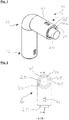
- a solid fuel hearth furnace tube 10 according to the invention is shown.
- the solid fuel furnace tube 10 has a first connection section 12, an intermediate region 13 and a second connection section 14.
- the third tube 40 forms an outer jacket of the solid fuel furnace tube 10.
- This third pipe 40 has an air intake opening 42 in the second connection section 14. Supply air can pass through the supply air intake opening 42 into the interior space 41 formed between the third tube 40 and the cooling tube 30 of the third tube 40.
- the third tube 40 is composed of three cohesively joined components.
- the third pipe 40 surrounds or sheaths the cooling pipe 30, which in turn surrounds or sheaths the exhaust pipe 20. In the second connection section 14, the exhaust pipe 20 projects beyond both the cooling pipe 30 and the third pipe 40.
- FIG. 2 a further embodiment of the invention of a solid fuel furnace tube 10 is shown, which in principle corresponds to that in FIG Figure 1 illustrated embodiment can fit.
- the solid fuel hearth furnace tube 10 has an exhaust gas tube 20 which is concentrically surrounded by the cooling tube 30.
- the cooling tube 30 is also surrounded concentrically by the third tube 40.
- the interior 41 of the third pipe 40 is pierced by a connecting line 48, which therefore creates a fluidically conductive connection between the environment and the second cooling opening 34, so that air from the environment into the interior 36 of the cooling pipe 30, which is enclosed by the cooling pipe 30 and the exhaust pipe 20 can arrive.
- the third tube 40 has a multiplicity of connecting openings 46.
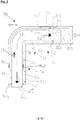
- the solid fuel furnace tube 10 has an intermediate region 13 which is arranged between the first connection section 12 and the second connection section 14 and is curved by 90 °.
- the solid fuel furnace tube 10 has an internally arranged exhaust gas pipe 20, a cooling pipe 30 surrounding it, and an external third pipe 40 which surrounds the cooling pipe 30.
- the exhaust pipe 20 has an exhaust gas intake opening 22 in the first connection section 12 and an exhaust gas outlet opening 24 in the second connection section 14.
- the exhaust gas intake opening 22 and the exhaust gas outlet opening 24 are fluidically connected to one another through the interior 28 of the exhaust gas pipe 20, so that an exhaust gas flow AB from the exhaust gas intake opening 22 can flow to the exhaust gas outlet opening 24.
- the exhaust pipe 20 has a diameter D20.
- the exhaust pipe 20 is supported by the support element 26 against the cooling pipe 30, the cooling pipe 30 concentrically surrounding the exhaust pipe 20 in the intermediate section 13, in the first connection section 12 and in the second connection section 14.
- the cooling pipe 30 has a first cooling opening 32 in the first connection section 12 and a second cooling opening 34 in the second connection section 14.
- the first cooling opening 32 and the second cooling opening 34 are each fluidically connected to the environment via a connection line 48 and connection openings 46. It is thus possible that the heat generated during operation can form a convective cooling flow between the first and second cooling openings 32, 34, so that the cooling pipe 30 is significantly cooler on its outside than the exhaust pipe 20.
- the third pipe 40 is supported with respect to the cooling pipe 30 through the connecting lines 48.
- Air from the environment can flow through the connection opening 46 in the first connection section 12 through the connection lines 48 and through the first cooling opening 32 into the interior space 36 of the cooling pipe 30 formed between the cooling pipe 30 and the exhaust pipe 20 and form a cooling air flow KU there.
- the air or the cooling air flow KU can then flow through this interior 36 of the cooling tube 30 to the second cooling opening 34 and flow through this via the connecting line 48 and the slot-like connecting openings 46 into the surroundings.
- both the exhaust pipe 20, the cooling pipe 30 and the third pipe 40 extend in the first connection direction A1.
- the exhaust pipe 20, the cooling pipe 30 and the third pipe 40 extend in the second connection direction A2.
- the first connection direction A1 is perpendicular to the second connection direction A2.
- the exhaust pipe 20 has a diameter D20
- the cooling pipe 30 has a diameter D30
- the third pipe 40 has a diameter D40.
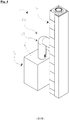
- a solid fuel fireplace system 1 is shown. This comprises on the one hand a solid fuel hearth 2 and a solid hearth furnace tube 10.
- the solid hearth furnace 2 is connected to the chimney 4 via the solid hearth furnace tube 10.
- the solid fuel furnace tube 10 is connected to the cover 6 of the solid fuel furnace 2.
- FIG. 5 a connection situation of a solid fuel hearth furnace pipe 10 to a chimney 4 is shown.
- a cover plate 70 is arranged between the chimney 4 and the third pipe 40 of the solid fuel furnace pipe 10.
- the cover plate 70 has a fixing section 78 for fixing on the chimney 4.
- a cover plate 70 according to the invention is shown.
- the cover plate 70 has a collar area 72 and a fixing section 78.
- the fixing section 78 is used to fix the cover plate relative to a chimney.
- the cantilever area 72 of the cover plate 70 has an opening 74 or forms an opening 74.
- the solid fuel fireplace adapter piece 50 comprises a first connecting section 51 and a second connecting section 52, the first connecting section 51 being designed to be attached to a chimney 4 and / or to a solid fuel fireplace 2.
- the second connecting section 52 is designed to be attached to a solid fuel hearth furnace tube 10.
- the solid fuel fireplace adapter piece 50 has an exhaust gas cross section 54 and an air intake cross section 56.
- An exhaust gas flow can be passed through the exhaust gas cross section 54 and an air intake flow through the air intake cross section 56 Flow solid hearth adapter 50.
- the exhaust gas cross section 54 is surrounded concentrically by the supply air cross section 56 over the entire length of the solid fuel fireplace adapter piece 50.
Landscapes
- Engineering & Computer Science (AREA)
- Mechanical Engineering (AREA)
- General Engineering & Computer Science (AREA)
- Heat-Exchange Devices With Radiators And Conduit Assemblies (AREA)
- Solid-Fuel Combustion (AREA)
- Waste-Gas Treatment And Other Accessory Devices For Furnaces (AREA)
Description
- Die Erfindung betrifft ein Feststofffeuerstellenofenrohr, ein Feststofffeuerstellenadapterstück, eine Abdeckplatte sowie ein Feststofffeuerstellensystem.
- Feststofffeuerstellenanschlusssysteme sind bereits aus dem Stand der Technik bekannt, diese dienen dazu, eine Feststofffeuerstelle, wie z.B. einen mit Holz befeuerten Ofen, mit einem Kamin derart zu verbinden, sodass die Verbrennungsgase von der Feuerstelle in den Kamin gelangen können. Um diesen Anschluss an die Feuerstelle und/oder den Kamin zu erreichen verfügen Anschlusssysteme zumindest über ein Ofenrohr. Darüber hinaus können solche Systeme auch noch Adapterstücke umfassen, um den Anschluss des Ofenrohrs am Kamin oder den Anschluss des Ofenrohrs an der Feuerstelle zu erreichen. Problematisch bei den bereits bekannten Feststofffeuerstellenanschlusssystemen ist, dass diese an ihrer Außenseite sehr heiß werden können, sodass unter anderem eine hohe Verletzungsgefahr für Personen besteht.
- Die
US 987,792 zeigt ein Heizungs- und Ventilationssystem, welches insbesondere für die Verwendung in Schulräumen, Hallen oder ähnlichen Räumen ausgelegt ist. Ein Kühlrohr ist konzentrisch um das Abgasrohr eines fens angeordnet. - Die
US 886,391 betrifft ein Ventilationssystem für Räume umfassend eine zylindrische Trommel, welche ein Rohr für eine Feuerstelle umgibt. - Die
DE 87 03 869 U1 betrifft einen Heizkessel, der aus einem wasserführenden Gehäuse besteht, in dem die gasführenden und abzugsseitig in einen Abgasabzugsstutzen mit Abzugsrohr einmündenden Räume angeordnet sind. - Es ist daher Aufgabe der vorliegenden Erfindung eine Anschlussmöglichkeit für eine Feststofffeuerstelle an einen Kamin bereitzustellen, welche nur eine geringe Gefahr von Verletzungen aufweist.
- Diese Aufgabe wird mit einem Feststofffeuerstellenofenrohr gemäß Anspruch 1, und mit einem Feststofffeuerstellensystem gemäß Anspruch 12 gelöst.
- Erfindungsgemäß umfasst ein Feststofffeuerstellenofenrohr einen ersten Anschlussabschnitt, einen Zwischenbereich, einen zweiten Anschlussabschnitt, ein Abgasrohr und ein Kühlrohr, wobei sich der Zwischenbereich zwischen dem ersten und dem zweiten Anschlussabschnitt erstreckt, wobei der erste Anschlussabschnitt dazu ausgelegt ist, an einer Feststofffeuerstelle mittel- und/oder unmittelbar angeschlossen zu sein, wobei der zweite Anschlussabschnitt dazu ausgelegt ist, an einem Kamin mittel- und/oder unmittelbar angeschlossen zu sein, wobei das Abgasrohr im ersten Anschlussabschnitt eine Abgasaufnahmeöffnung aufweist, welche dazu ausgelegt ist, mit einem Abgasaustritt einer Feststofffeuerstelle mittel- und/oder unmittelbar verbunden zu sein, wobei das Abgasrohr im zweiten Anschlussabschnitt eine Abgasauslassöffnung aufweist, welche dazu ausgelegt ist, mit einem Kaminabgasrohr mittel- und/oder unmittelbar verbunden zu sein, wobei das Kühlrohr im ersten Anschlussabschnitt eine erste Kühlöffnung und im zweiten Anschlussabschnitt eine zweite Kühlöffnung aufweist, wobei der vom Kühlrohr umschlossene Innenraum fluidisch mit der Umgebung durch die erste Kühlöffnung und durch die zweite Kühlöffnung verbunden ist, wobei das Kühlrohr das Abgasrohr, zumindest im Zwischenbereich, umgibt, insbesondere konzentrisch. Das Feststofffeuerstellenofenrohr dient generell dazu, eine Feststoffbrennstelle mit einem Kamin derart zu verbinden, so dass Abgase aus der Feststofffeuerstelle in den Kamin gelangen können. Eine Feststofffeuerstelle ist dabei eine Feuerstelle, welche mit Festbrennstoffen betrieben wird, wie beispielsweise Kohle, Holz oder Pellets. Die Feststofffeuerstelle kann dabei insbesondere ein Ofen sein, welcher in Wohnräumen von Einzelhäusern zu finden ist. Der Kamin, mit welchem das Feststofffeuerstellenofenrohr mittel- und/oder unmittelbar verbunden ist, kann dabei der Teil des Gebäudes sein, welcher dazu dient, das Abgas der Feststofffeuerstelle in die Umgebung/Umwelt um das Gebäude abzuleiten. Das Feststofffeuerstellenofenrohr dient in anderen Worten dazu, die Abgase aus einer Feststofffeuerstelle in den Kamin zu leiten. Hierzu kann das Feststofffeuerstellenofenrohr in einem eingebauten Zustand zumindest bereichsweise horizontal angeordnet sein. Das Feststofffeuerstellenofenrohr weist dabei einen ersten Anschlussabschnitt und einen zweiten Anschlussabschnitt auf, wobei zwischen diesen beiden Anschlussabschnitten sich der Zwischenbereich erstreckt. Der erste Anschlussabschnitt dient dabei dazu, insbesondere in einem eingebauten Zustand, an der Feststofffeuerstelle festgelegt zu werden und/oder zu sein und der zweite Anschlussabschnitt dient dazu, insbesondere in einem eingebauten Zustand, am Kamin mittel- und/oder unmittelbar angeschlossen zu sein. Das Feststofffeuerstellenofenrohr verfügt über ein Abgasrohr, welches im ersten Anschlussabschnitt eine Abgasaufnahmeöffnung aufweist, und im zweiten Anschlussabschnitt eine Abgasauslassöffnung. Das Abgasrohr dient daher dazu, die von der Feststofffeuerstelle produzierten Abgase vom ersten Anschlussabschnitt zum zweiten Anschlussabschnitt fluidisch zu leiten. Hierzu ist die Abgasauslassöffnung mit einem Kaminabgasrohr und die Abgasaufnahmeöffnung mit einem Abgasaustritt der Feuerstelle fluidisch verbunden. In anderen Worten bedeutet dies, dass das Abgasrohr die Abgasaufnahmeöffnung mit der Abgasauslassöffnung fluidisch verbindet. Fluidisch verbinden/leiten kann dabei unter anderem bedeuten, dass von der Aufnahmeöffnung zur Auslassöffnung ein Fluid, insbesondere kanalartig, strömen kann. Insbesondere ist das Abgasrohr derart gestaltet, dass dessen Innenraum lediglich über eine Abgasaufnahmeöffnung und eine Abgasauslassöffnung fluidisch verbunden ist, so dass kein Abgas an anderen Öffnungen das Abgasrohr verlassen kann. Zusätzlich zu dem Abgasrohr weist das Feststofffeuerstellenofenrohr auch ein Kühlrohr auf, welches im ersten Anschlussabschnitt eine erste Kühlöffnung und im zweiten Anschlussabschnitt eine zweite Kühlöffnung aufweist und wobei diese Kühlöffnungen dazu ausgelegt sind, dass ein Fluid in bzw. aus dem von dem Kühlrohr umschlossenen Innenraum in die Umgebung fließen kann. In anderen Worten kann dies bedeuten, dass der von dem Kühlrohr umschlossene Innenraum fluidisch über die erste Kühlöffnung und die zweite Kühlöffnung mit der Umgebung verbunden ist. Insbesondere ist das Kühlrohr derart ausgestaltet, dass der Innenraum des Kühlrohres ausschließlich über die Kühlöffnungen mit der Umgebung fluidisch verbunden ist. Insbesondere dient das Kühlrohr nicht dazu, Verbrennungsluft zu der Feststofffeuerstelle zu leiten und/oder Abgase von der Feststofffeuerstelle weg zu führen. Die Umgebung ist dabei in diesem Zusammenhang insbesondere die Raumluft, insbesondere eines Innenraumes, welche das Feststofffeuerstellenofenrohr umgibt. Vorteilhafterweise münden die Kühlöffnungen des Kühlrohres daher in einen einzigen Innenraum eines Raumes. Zweckmäßigerweise sind die Kühlöffnungen des Feststofffeuerstellenofenrohres maximal 1,2m, bevorzugt maximal 1m, besonders bevorzugt maximal 0,7m und besonders stark bevorzugt maximal 0,6m voneinander beabstandet, denn die Kühlöffnungen des Kühlrohres dienen insbesondere ausschließlich dazu, das Innere des Kühlrohrs mit der Raumlauft des umgebenden Innenraumes eines Gebäudes zu verbinden. Das Kühlrohr und das Abgasrohr sind dabei derart in dem Feststofffeuerstellenofenrohr angeordnet, so dass das Kühlrohr das Abgasrohr zumindest im Zwischenbereich umgibt. Insbesondere umgibt das Kühlrohr das Abgasrohr dabei derart, dass diese beiden Rohre zumindest im Zwischenbereich konzentrisch zueinander angeordnet sind. Vorteilhafterweise umgibt dabei das Kühlrohr das Abgasrohr nicht nur im Zwischenbereich, sondern auch zum überwiegenden Teil im ersten Anschlussabschnitt und/oder im zweiten Anschlussabschnitt. Umgeben bedeutet dabei in diesem Zusammenhang generell, dass das eine Rohr das andere Rohr in Umfangsrichtung und/oder in Längsrichtung zumindest bereichsweise, bevorzugt zum überwiegenden Teil, besonders stark bevorzugt vollständig umgibt bzw. ummantelt. Beispielsweise ist ein umgeben dann gegeben, wenn der Innenraum des Kühlrohrs ein Spalt, insbesondere ein Ringspalt, ist, dessen Volumen/Querschnitt nach außen durch das Kühlrohr und nach innen durch das Abgasrohr begrenzt ist. Alternativ oder zusätzlich bevorzugt kann umgeben auch bedeuten, dass kein Fluidfluss von dem Innenraum des einen Rohrs in das andere Rohr möglich ist, und dass darüber hinaus auch noch das eine Rohr durch das andere Rohr zumindest bereichsweise, bevorzugt zum überwiegenden Teil, ummantelt ist. Durch das Umgeben des Abgasrohres durch das Kühlrohr und dem in dem Kühlrohr durch die Erwärmung stattfindenden Fluidflusses, ist das Kühlrohr an seiner Außenhaut deutlich kühler als das Abgasrohr. Somit ist es für eine Person, zumindest im Zwischenbereich, nicht möglich oder nur schwer möglich, das heiße Abgasrohr zu berühren, sondern lediglich das deutlich kühlere Kühlrohr, so dass durch den Einsatz des Kühlrohres die Verletzungsgefahr deutlich reduziert werden kann.
- Vorteilhafterweise erstreckt sich das Abgasrohr im ersten Anschlussabschnitt entlang einer ersten Anschlussrichtung und/oder wobei sich das Abgasrohr im zweiten Anschlussabschnitt entlang einer zweiten Anschlussrichtung erstreckt. Durch diese gradlinige Ausgestaltung des ersten Anschlussabschnitts entlang einer ersten Anschlussrichtung und/oder des zweiten Anschlussabschnitts entlang einer zweiten Anschlussrichtung kann die Montage des Feststofffeuerstellenofenrohres deutlich vereinfacht werden. Darüber hinaus vereinfacht sich durch diese Maßnahme nicht nur die Montage, sondern zusätzlich kann hierdurch auch dessen Fertigung vereinfacht werden, so dass Kosten gespart werden können.
- Zweckmäßigerweise ist der Zwischenbereich gekrümmt und/oder gerade. Hierdurch kann die Montierbarkeit des Feststofffeuerstellenofenrohrs vereinfacht werden. Vorteilhafterweise ist der Zwischenbereich derart gestaltet, dass dieser um einen Winkel von 80° bis 100° gekrümmt ist. Hierdurch kann erreicht werden, dass das Feststofffeuerstellenofenrohr bereits werksbedingt an die meisten vorhandenen Einbausituationen angepasst ist, so dass Kosten bei dem endgültigen Einbau gespart werden können.
- Bevorzugt überragt das Abgasrohr im ersten Anschlussabschnitt das Kühlrohr in Richtung der ersten Anschlussrichtung und/oder wobei das Abgasrohr im zweiten Anschlussabschnitt das Kühlrohr in Richtung der zweiten Anschlussrichtung überragt. Durch dieses Überragen des Abgasrohres gegenüber dem Kühlrohr kann die Montage vereinfacht werden, denn der überragende Teil des Kühlrohrs kann als eine Art Führungseinheit verwendet werden. Überragen bedeutet dabei in diesem Zusammenhang, dass das Abgasrohr sich in die jeweilige Anschlussrichtung weiter in dem jeweiligen Anschlussabschnitt erstreckt als das Kühlrohr. Bevorzugt liegt das Verhältnis der überragenden Länge in die erste und/oder in die zweite Anschlussrichtung zum mittleren Außendurchmesser des Abgasrohres dabei in einem Bereich von 0,55 bis 0,75, denn die Anmelderin hat überraschend herausgefunden, dass bei einem solchen Verhältnis eine besonders intuitive Montage für den Monteur resultiert, so dass Kosten bei der Montage gespart werden können.
- Bevorzugt weist das Abgasrohr eine Revisionsöffnung auf. Diese Revisionsöffnung ermöglicht dabei, dass das Ofenrohr einfach gereinigt und/oder inspiziert werden kann. Um ein besonders hohes Maß an Zugänglichkeit zu schaffen, ist es bevorzugt, wenn die Revisionsöffnung im Zwischenbereich angeordnet ist, insbesondere im gekrümmten Teil des Zwischenbereichs. Die Revisionsöffnung ist dabei vorteilhafterweise derart gestaltet, dass diese einen Zugriff in den Innenraum des Abgasrohrs ermöglicht. Besonders bevorzugt ermöglicht die Revisionsöffnung jedoch keinen Zugriff in den Innenraum des Kühlrohrs. In anderen Worten kann dies bedeuten, dass durch die Revisionsöffnung der Innenraum des Abgasrohrs mit der Umgebung fluidisch temporär verbunden werden kann nicht jedoch der Innenraum des Kühlrohrs. Zweckmäßigerweise ist die Revisionsöffnung mittels eines Verschlusselements verschließbar.
- Zweckmäßigerweise ist das Abgasrohr im ersten Anschlussabschnitt konisch ausgebildet und/oder wobei das Abgasrohr im zweiten Anschlussabschnitt konisch ausgebildet ist. Hierdurch kann auf einfache Weise eine besonders hohe Dichtwirkung erreicht werden. Darüber hinaus kann durch diese Maßnahme auch noch erreicht werden, dass teure Dichtelemente eingespart werden können, so dass ein besonders kostengünstiges Feststofffeuerstellenofenrohr erreicht wird. Der konische Abschnitt des Abgasrohres ist dabei insbesondere derart gestaltet, dass dieser sich in Richtung zum distalen Ende des ersten und/oder des zweiten Anschlussabschnitts hin verjüngt oder erweitert. In anderen Worten kann dies bedeuten, dass der Konus - ähnlich eines Pfeils - vom Zwischenbereich bzw. vom jeweiligen Anschlussabschnitt weg oder zu diesem hin weist. Vorteilhafterweise liegt die Steigung des Konus dabei in einem Bereich von 0,05° bis 5°, besonders im Bereich von 0,1 bis 3° und besonders stark bevorzugt im Bereich von 0,5° bis 2,5°. Bei einer Steigung des Konus im Bereich von 0,05° bis 5° kann eine besonders hohe Dichtwirkung erreicht werden. Um eine besonders leichte Montage des Feststofffeuerstellenofenrohrs zu erreichen, sollte die Steigung des Konus in einem Bereich von 0,1° bis 3° liegen. Überraschenderweise hat die Anmelderin herausgefunden, dass der Konus besonders einfach herzustellen ist, wenn dessen Steigung im Bereich zwischen 0,5° bis 3° liegt, so dass ein besonders kostengünstiges Feststofffeuerstellenofenrohr resultiert.
- Zweckmäßigerweise umgibt das Kühlrohr das Abgasrohr im ersten Anschlussabschnitt und/oder im zweiten Anschlussabschnitt zumindest bereichsweise, bevorzugt zum überwiegenden Teil, insbesondere konzentrisch. Hierdurch kann die Verletzungsgefahr weiter reduziert werden. Insbesondere existiert zumindest ein Querschnitt, in welchem das Kühlrohr im ersten und/oder im zweiten Anschlussabschnitt das Abgasrohr vollständig umfänglich, insbesondere konzentrisch, umgibt.
- Bevorzugt besteht das Kühlrohr und/oder das Abgasrohr zumindest zum überwiegenden Teil, insbesondere vollständig, aus Edelstahl oder Schwarzblech. Hierdurch kann ein besonders hoch temperaturfestes Feststofffeuerstellenofenrohr erreicht werden.
- Vorteilhafterweise ist zwischen dem Abgasrohr und dem Kühlrohr zumindest ein Abstützelement, bevorzugt eine Vielzahl von Abstützelementen, insbesondere im Innenraum des Kühlrohrs, angeordnet. Hierdurch kann eine besonders bauraumsparende und mechanisch belastbare Abstützung des Kühlrohrs gegenüber dem Abgasrohr erreicht werden. Vorteilhafterweise ist das oder sind die Abstützelemente dabei stoffschlüssig, insbesondere mittels einer Schweißnaht, mit dem Abgasrohr und/oder mit dem Kühlrohr verbunden. Besonders zweckmäßig ist es, um eine einfache und kostengünstige Herstellung zu erreichen, wenn die Abstützelemente im ersten Anschlussabschnitt und/oder im zweiten Anschlussabschnitt angeordnet sind. Zusätzlich oder alternativ bevorzugt sind die Abstützelemente dabei gleichmäßig in Umfangsrichtung und/oder in Längsrichtung angeordnet. Die Umfangsrichtung ist dabei die Umfangsrichtung um die Längsrichtung. Unter Längsrichtung ist dabei in diesem Zusammenhang insbesondere die Verbindungsrichtung vom ersten Anschlussabschnitt zum zweiten Anschlussabschnitt zu verstehen, wobei diese Verbindungsrichtung dabei nicht unbedingt immer geradlinig sein muss. In anderen Worten kann die Längsrichtung dabei diejenige Richtung sein, welche der mittleren Strömungsrichtung in dem Querschnitt, insbesondere innerhalb des Abgasrohres, bei einer Strömung vom ersten Anschlussabschnitt zum zweiten Anschlussabschnitt entspricht.
- Vorteilhafterweise liegt das Verhältnis des Durchmessers des Abgasrohrs zu dem Durchmesser des Kühlrohrs in einem Bereich von 0,5 bis 0,95, bevorzugt in einem Bereich von 0,6 bis 0,85 und besonders stark bevorzugt in einem Bereich von 0,7 bis 0,8. Der maßgebliche Durchmesser ist dabei der Innendurchmesser oder der Außendurchmesser des jeweiligen Rohrs. Bei einem nicht kreisförmigen Querschnitt ist der Durchmesser der Durchmesser des kleinstmöglichen Kreises, welcher gerade die Innen-/Außenkontur des maßgeblichen Rohrquerschnitts umgibt. Bei einem Verhältnis des Durchmessers des Abgasrohres zu dem Durchmesser des Kühlrohres im Bereich von 0,5 bis 0,9 kann eine besonders gute Kühlwirkung erreicht werden. Um eine einfache Herstellung des Feststofffeuerstellenofenrohrs zu erreichen, liegt das Verhältnis des Durchmessers des Abgasrohres zu dem Durchmesser des Kühlrohres im Bereich von 0,6 bis 0,85. Um ein besonders kompaktes Feststofffeuerstellenofenrohr zu erreichen, sollte das Verhältnis des Durchmessers des Abgasrohres zu dem Durchmesser des Kühlrohres in einem Bereich von 0,7 bis 0,8 liegen.
- Zweckmäßigerweise weist das Abgasrohr und/oder das Kühlrohr, insbesondere im ersten Anschlussabschnitt und/oder im zweiten Anschlussabschnitt, einen runden, insbesondere kreisförmigen Querschnitt auf. Ein runder Querschnitt ist unter anderem dann gegeben, wenn die Innen- und/oder die Außenkontur des Querschnitts zumindest bereichsweise rund ausgestaltet ist. Beispielsweise ist ein runder Querschnitt unter anderem dann gegeben, wenn dieser Querschnitt eine elliptische oder kreisförmige Innen- und/oder Außenkontur aufweist. In anderen Worten kann dies bedeuten, dass das Abgasrohr und/oder das Kühlrohr zumindest im ersten Anschlussabschnitt und/oder im zweiten Anschlussabschnitt runde Rohre sein können. Durch den zumindest bereichsweise runden Querschnitt des Abgasrohres und/oder des Kühlrohres kann ein besonders vorteilhaftes Verhältnis zwischen Mantelfläche und umschlossenem Volumen bzw. umschlossener Fläche erreicht werden, so dass Material eingespart werden kann.
- Erfindungsgemäß umfasst das Feststofffeuerstellenofenrohr ein drittes Rohr, wobei das dritte Rohr eine Zuluftaufnahmeöffnung und eine Zuluftauslassöffnung aufweist, wobei die Zuluftaufnahmeöffnung im zweiten Anschlussabschnitt angeordnet ist, wobei das dritte Rohr das Kühlrohr, zumindest im zweiten Anschlussabschnitt, umgibt, insbesondere konzentrisch. Die Zuluftaufnahmeöffnung ist dazu ausgelegt das Zuluft in das dritte Rohr strömen kann und dort durch den vom dritten Rohr umschlossenen Innenbereich fluidisch zu der Zuluftauslassöffnung geleitet wird. Dieser vom dritten Rohr umschlossene Innenbereich wird dabei insbesonde durch das dritte Rohr, insbesondere nach außen, und durch das Kühlrohr, insbesondere nach innen, zumindest teilweise begrenzt bzw. umschlossen. In anderen Worten kann das Feststofffeuerstellenofenrohr nicht nur dazu ausgelegt sein, Abgase bzw. Verbrennungsabgase von der Feststofffeuerstelle zum Kamin fluidisch zu leiten, sondern zusätzlich kann das Feststofffeuerstellenofenrohr auch noch dazu dienen, Zuluft bzw. Verbrennungsluft zur Feststofffeuerstelle, insbesondere vom Kamin, zu leiten. Somit kann das Feststofffeuerstellenofenrohr auch für Raumluft unabhängige Feststofffeuerstellen eingesetzt werden. Durch das Umgeben des Kühlrohres durch das dritte Rohr kann nicht nur die Verbrennungsgefahr weiter reduziert werden, sondern zusätzlich wird hierdurch auch noch erreicht, dass die Zuluft besonders kühl ist, so dass diese eine besonders hohe Dichte aufweist. Besonders bevorzugt ist es, wenn das dritte Rohr das Kühlrohr nicht nur im zweiten Anschlussabschnitt umgibt, sondern zusätzlich das Kühlrohr auch im Zwischenbereich und/oder im ersten Anschlussabschnitt umgibt.
- Zweckmäßigerweise ist das dritte Rohr durch stoffschlüssig gefügte Komponenten gebildet. Hierdurch resultiert eine besonders einfache und kostengünstige Herstellung des dritten Rohrs bzw. des Feststofffeuerstellenofenrohrs, so dass Kosten gespart werden können. Alternativ oder zusätzlich bevorzugt können auch das Kühlrohr und/oder das Abgasrohr aus stoffschlüssig gefügten Komponenten gebildet sein. Durch die stoffschlüssigen, insbesondere durch Schweißen, gefügten Komponenten resultiert ein besonders kostengünstiges Abgasrohr und/oder Kühlrohr.
- Bevorzugt umgibt das dritte Rohr das Kühlrohr im ersten Anschlussabschnitt und/oder im Zwischenbereich. Hierdurch kann die Sicherheit des Feststofffeuerstellenofenrohrs weiter gesteigert werden.
- Bevorzugt besteht das dritte Rohr zumindest zum überwiegenden Teil, insbesondere vollständig, aus Edelstahl oder Schwarzblech. Hierdurch kann ein besonders hoch temperaturfestes drittes Rohr erreicht werden. Darüber hinaus bietet der Einsatz von Edelstahl oder Schwarzblech auch noch den Vorteil, dass das dritte Rohr hohen mechanischen Belastungen widerstehen kann.
- Bevorzugt weist das dritte Rohr zumindest eine Verbindungsöffnung auf, wobei eine Verbindungsleitung die erste Kühlöffnung oder die zweite Kühlöffnung mit der Verbindungsöffnung fluidisch verbindet. In anderen Worten kann dies bedeuten, dass sich durch den vom dritten Rohr umschlossenen Innenraum zumindest eine Verbindungsleitung, insbesondere eine Vielzahl von Verbindungsleitungen, erstreckt, welche fluidisch die erste Kühlöffnung oder die zweite Kühlöffnung mit einer Verbindungsöffnung des dritten Rohrs verbindet. Hierdurch wird erreicht, dass ein Fluid aus der Umgebung in das Kühlrohr strömen kann. Beispielsweise kann daher ein Fluid ausgehend von der Umgebung die Verbindungsöffnung, die Verbindungsleitung und anschließend die erste oder die zweite Kühlöffnung durchströmen, um so in den Innenraum des Kühlrohrs zu gelangen. Hierdurch ist in einfacher Weise ein Einströmen oder Ausströmen von Luft aus dem Innenraum des Kühlrohrs in die Umgebung möglich. Zusätzlich können diese Verbindungsleitungen auch noch dazu dienen, das dritte Rohr relativ zum Kühlrohr festzulegen bzw. zu lagern. Besonders bevorzugt ist es, wenn eine Vielzahl von Verbindungsleitungen vorhanden ist. Hierdurch kann die Kühlleistung des Feststofffeuerstellenofenrohrs weiter gesteigert werden.
- In einer bevorzugten Ausführungsform liegt das Verhältnis des Durchmessers des Abgasrohres zu dem Durchmesser des dritten Rohres in einem Bereich von 0,3 bis 0,8, bevorzugt in einem Bereich von 0,4 bis 0,7 und besonders stark bevorzugt in einem Bereich von 0,5 bis 0,65. Um eine besonders hohe Kühlwirkung zu erreichen, sollte das Verhältnis in einem Bereich von 0,3 bis 0,8 liegen. Bei einem Verhältnis im Bereich von 0,4 bis 0,7 resultiert ein besonders vorteilhaftes Verhältnis zwischen dem eingesetzten Material in Relation zur Kühlwirkung, so dass ein relativ kostengünstiges Feststofffeuerstellenofenrohr resultiert. Bei einem Verhältnis des Durchmessers des Abgasrohres zu dem Durchmesser des dritten Rohres im Bereich von 0,5 bis 0,65 resultiert ein besonders bauraumsparendes Feststofffeuerstellenofenrohr.
- Ein weiterer Aspekt der Erfindung betrifft ein Feststofffeuerstellenadapterstück, umfassend einen ersten Verbindungsabschnitt und einen zweiten Verbindungsabschnitt, wobei der erste Verbindungsabschnitt dazu ausgelegt ist, an einem Kamin und/oder an einer Feststofffeuerstelle festgelegt zu sein, wobei der zweite Verbindungsabschnitt dazu ausgelegt ist, an einem Feststofffeuerstellenofenrohr, insbesondere einem erfindungsgemäßen Feststofffeuerstellenofenrohr, festgelegt zu sein. Das Feststofffeuerstellenadapterstück dient in anderen Worten daher insbesondere dazu, zwischen dem Feststofffeuerstellenofenrohr und einem Kamin oder einer Feststofffeuerstelle und dem Feststofffeuerstellenofenrohr angeordnet zu sein. Durch das Feststofffeuerstellenadapterstück kann der Anschluss des Feststofffeuerstellenofenrohrs am Kamin und/oder an der Feuerstelle vereinfacht werden, da die für das Feststofffeuerstellenofenrohr zur Verfügung stehende Schnittstelle durch das Feststofffeuerstellenadapterstück klar definiert ist, so dass das Feststofffeuerstellenofenrohr in vielen - möglicherweise grundlegend unterschiedlichen - Einbausituationen eingesetzt werden kann. Der erste Verbindungsabschnitt des Feststofffeuerstellenadapterstücks dient dazu, eine mechanisch und/oder fluidische Verbindung zum Kamin und/oder zur Feststofffeuerstelle zu erreichen. Der zweite Verbindungsabschnitt des Feststofffeuerstellenadapterstücks hingegen dient dazu, eine mechanische und/oder eine fluidische Verbindung zwischen dem Feststofffeuerstellenadapterstück und dem Feststofffeuerstellenofenrohr herzustellen.
- In einer vorteilhaften Ausführungsform ist im ersten Verbindungsabschnitt und/oder im zweiten Verbindungsabschnitt ein Abgasquerschnitt und ein Zuluftquerschnitt vorhanden, wobei der Zuluftquerschnitt den Abgasquerschnitt, insbesondere konzentrisch, umgibt. Der Zuluftquerschnitt, insbesondere Zuluftringquerschnitt, ist dabei der in einem Betrieb von der Zuluft durchströmte Querschnitt des Feststofffeuerstellenadapterstücks. Der Abgasquerschnitt ist insbesondere der Querschnitt, durch welchen die Abgase der Feuerstätte im ersten Verbindungsabschnitt und/oder im zweiten Verbindungsabschnitt strömen. In anderen Worten ist das Feststofffeuerstellenadapterstück im ersten Verbindungsabschnitt und/oder im zweiten Verbindungsabschnitt derart gestaltet, dass - ähnlich wie das Feststofffeuerstellenofenrohr - der Querschnitt, durch den die Zuluft zur Feuerstelle fließt, den Strömungsquerschnitt, welcher die Abgase fluidisch (weg)leitet, umgibt. Durch diese Art der Ausgestaltung des Feststofffeuerstellenadapterstücks kann die Kühlleistung des Feststofffeuerstellenadapterstücks und auch dessen Sicherheit gesteigert werden.
- In einer vorteilhaften Ausführungsform weist das Feststofffeuerstellenadapterstück einen dritten Verbindungsabschnitt auf, wobei der dritte Verbindungsabschnitt vom ersten und vom zweiten Verbindungsabschnitt beabstandet ist, wobei der dritte Verbindungsabschnitt eine Strömungsöffnung aufweist, wobei die Strömungsöffnung fluidisch mit dem Zuluftquerschnitt oder mit dem Abgasquerschnitt im ersten Verbindungsabschnitt oder im zweiten Verbindungsabschnitt verbunden ist. In anderen Worten kann dies bedeuten, dass das Feststofffeuerstellenadapterstück neben den Anschlussmöglichkeiten im ersten Verbindungsabschnitt und im zweiten Verbindungsabschnitt noch einen dritten Verbindungsabschnitt aufweist, wobei der dritte Verbindungsabschnitt dazu dient, Zuluft in das Feststofffeuerstellenadapterstück zu leiten und/oder Abgase aus diesem auszuleiten. Durch das Vorsehen eines dritten Verbindungsabschnitts resultiert ein Feststofffeuerstellenadapterstück, welches eine hohe Variabilität bezüglich der möglichen Einbausituationen aufweist. Insbesondere kann hierdurch erreicht werden, dass bereits vorhandene Systeme mit einem erfindungsgemäßen Feststofffeuerstellenadapterstück und/oder einem erfindungsgemäßen Feststofffeuerstellenofenrohr nachgerüstet werden können, so dass auch bei vorhandenen Systemen die Verbrennungsgefahr reduziert werden kann.
- Ein weiterer Aspekt der Erfindung betrifft eine Abdeckplatte, wobei die Abdeckplatte einen Kragenbereich und einen Fixierabschnitt umfasst, wobei der Kragenbereich einen, insbesondere kreisrunde, Durchbruch aufweist und/oder ausbildet, wobei der Kragenbereich eine konische vom Fixierabschnitt weg ragende Außenkontur aufweist, wobei der konische Kragenbereich dazu ausgelegt ist, mit einem Feststofffeuerstellenofenrohr, insbesondere mit einem dritten Rohr eines Feststofffeuerstellenofenrohrs, oder mit einem Feststofffeuerstellenadapterstück verbunden zu sein. Der Kragenbereich der Abdeckplatte ragt dabei insbesondere von dem Fixierabschnitt weg und ist dabei auch noch konisch ausgebildet. Der Durchbruch, welcher in dem Kragenbereich angeordnet ist, dient dazu, Abgase und/oder Zuluft durch die Abdeckplatte führen zu können. Der Fixierabschnitt der Abdeckplatte hingegen dient dazu, diese an einem Kamin und/oder einer Bauwand anzuordnen. Durch den Einsatz dieser Abdeckplatte ist es besonders einfach möglich, insbesondere ein erfindungsgemäßes, Feststofffeuerstellenofenrohr oder, insbesondere ein erfindungsgemäßes, Feststofffeuerstellenadapterstück zu montieren. Um die Herstellung zu vereinfachen ist der Fixierabschnitt der Abdeckplatte bevorzugt rechteckig bzw. quarderförmig ausgebildet. Um die Montage der Abdeckplatte zu vereinfachen, sind im Fixierabschnitt vorteilhafterweise Löcher vorgesehen, um Fixiermittel einfach zu platzieren bzw. aufzunehmen.
- Ein weiterer Aspekt der Erfindung betrifft ein Feststofffeuerstellensystem umfassend eine Feststofffeuerstelle und ein, insbesondere erfindungsgemäßes, Feststofffeuerstellenofenrohr. Hierdurch ist es möglich, dass das Feststofffeuerstellensystem die Vorteile aufweist, welche durch das Feststofffeuerstellenofenrohr bewirkt werden können. Die Feststofffeuerstelle kann beispielsweise ein mit Holz, Kohle und/oder Pellets befeuerter Ofen sein.
- In einer vorteilhaften Ausführungsform umfasst das Feststofffeuerstellensystem auch ein Feststofffeuerstellenadapterstück und/oder eine Abdeckplatte.
- In einer bevorzugten Ausführungsform weist die Feststofffeuerstelle einen Boden und einen Deckel auf, wobei der Deckel ein Abgasaustritt aufweist. Der Boden der Feststofffeuerstelle ist insbesondere der Bereich, mittels welchem die Feststofffeuerstelle auf einem Untergrund aufgestellt ist. Der Deckel der Feststofffeuerstelle hingegen begrenzt die Feststofffeuerstelle distal gegenüberliegend zum Boden. Der Abgasaustritt dient insbesondere dazu, dass Abgase aus den Innenraum bzw. aus den Brennraum der Feststofffeuerstelle gelangen können. Durch die Anordnung des Abgasaustritts im Deckel und dem Einsatz eines erfindungsgemäßen Feststofffeuerstellenofenrohrs ist es möglich, die Feststofffeuerstelle - ohne aufwendige Anpassungen - variabel anzuordnen, insbesondere durch eine Rotation um die Hochachse der Feststofffeuerstelle.
- In einer bevorzugten Weiterbildung weist der Deckel eine Verbrennungsluftzufuhröffnung auf, wobei die Verbrennungsluftzufuhröffnung den Abgasaustritt, insbesondere konzentrisch, umgibt. Die Verbrennungsluftzufuhröffnung dient insbesondere dazu, dass Zuluft in den Innenraum bzw. in den Brennraum der Feststofffeuerstelle gelangen kann. Hierdurch kann auch bei einer Raumluft unabhängigen Feststofffeuerstelle ein hohes Maß an Aufstellungsvariabilität erreicht werden.
- In einer vorteilhaften Ausführungsform weist die Feststofffeuerstelle einen Korpus auf, welcher den Boden und den Deckel umfasst, wobei der Korpus zum überwiegenden Teil aus Beton gebildet ist. Hierdurch resultiert eine besonders kostengünstige und mechanisch belastbare Feststofffeuerstelle.
- Weitere Vorteile und Merkmale der vorliegenden Erfindung ergeben sich aus der nachfolgenden Beschreibung mit Bezug auf die Figuren. Einzelne Merkmale der dargestellten Ausführungsformen können dabei auch in anderen Ausführungsformen eingesetzt werden, sofern dies nicht ausdrücklich ausgeschlossen wurde.
- Es zeigen
- Fig. 1
- eine perspektivische Ansicht eines erfindungsgemäßen Feststofffeuerstellenofenrohrs;
- Fig. 2
- eine Seitenansicht einer weiteren erfindungsgemäßen Ausführungsform eines Feststofffeuerstellenofenrohrs;
- Fig. 3
- eine Schnittansicht eines erfindungsgemäßen Feststofffeuerstellenofenrohrs;
- Fig. 4
- ein erfindungsgemäßes Feststofffeuerstellensystem;
- Fig. 5
- eine erfindungsgemäße Abdeckplatte;
- Fig. 6
- eine perspektivische Ansicht einer erfindungsgemäßen Abdeckplatte und
- Fig. 7
- ein erfindungsgemäßes Feststofffeuerstellenadapterstück.
- In der
Figur 1 ist ein erfindungsgemäßes Feststofffeuerstellenofenrohr 10 dargestellt. Das Feststofffeuerstellenofenrohr 10 verfügt dabei über einen ersten Anschlussabschnitt 12, einen Zwischenbereich 13 und einen zweiten Anschlussabschnitt 14. Das dritte Rohr 40 bildet einen äußeren Mantel des Feststofffeuerstellenofenrohrs 10 aus. Dieses dritte Rohr 40 weist dabei im zweiten Anschlussabschnitt 14 eine Zuluftaufnahmeöffnung 42 auf. Durch die Zuluftaufnahmeöffnung 42 kann Zuluft in den - zwischen dem dritten Rohr 40 und dem Kühlrohr 30 gebildeten Innenraum 41 - des dritten Rohres 40 gelangen. Das dritte Rohr 40 ist dabei aus drei stoffschlüssig gefügten Bauteilen zusammengesetzt. Das dritte Rohr 40 umgibt bzw. ummantelt dabei das Kühlrohr 30, welches wiederum das Abgasrohr 20 umgibt bzw. ummantelt. Im zweiten Anschlussabschnitt 14 überragt das Abgasrohr 20 sowohl das Kühlrohr 30 als auch das dritte Rohr 40. - In der
Figur 2 ist eine weitere erfindungsgemäße Ausführungsform eines Feststofffeuerstellenofenrohrs 10 gezeigt, welches prinzipiell zu der in derFigur 1 dargestellten Ausführungsform passen kann. Das Feststofffeuerstellenofenrohr 10 weist dabei ein Abgasrohr 20 auf, welches konzentrisch durch das Kühlrohr 30 umgeben ist. Das Kühlrohr 30 ist dabei ebenfalls konzentrisch durch das dritte Rohr 40 umgeben. Den Innenraum 41 des dritten Rohres 40 durchstößt dabei eine Verbindungsleitung 48, welche daher eine fluidisch leitende Verbindung zwischen der Umgebung und der zweiten Kühlöffnung 34 erschafft, so dass Luft von der Umgebung in den vom Kühlrohr 30 und dem Abgasrohr 20 umschlossenen Innenraum 36 des Kühlrohres 30 gelangen kann. Um ein Einströmen von Luft in die Verbindungsleitung 48 zu ermöglichen, weist das dritte Rohr 40 eine Vielzahl von Verbindungsöffnungen 46 auf. - In der
Figur 3 ist ein Schnitt von A-A aus der in derFigur 2 dargestellten Ausführungsform gezeigt. - Das Feststofffeuerstellenofenrohr 10 weist einen Zwischenbereich 13 auf, welcher zwischen dem ersten Anschlussabschnitt 12 und dem zweiten Anschlussabschnitt 14 angeordnet ist und um 90° gekrümmt ist. Darüber hinaus verfügt das Feststofffeuerstellenofenrohr 10 über ein innerlich angeordnetes Abgasrohr 20, einem dieses umgebende Kühlrohr 30 und ein äußeres drittes Rohr 40, welches das Kühlrohr 30 umgibt.
- Das Abgasrohr 20 verfügt im ersten Anschlussabschnitt 12 über eine Abgasaufnahmeöffnung 22 und im zweiten Anschlussabschnitt 14 über eine Abgasauslassöffnung 24. Die Abgasaufnahmeöffnung 22 und die Abgasauslassöffnung 24 sind dabei fluidisch durch den Innenraum 28 des Abgasrohres 20 miteinander verbunden, so dass ein Abgasstrom AB von der Abgasaufnahmeöffnung 22 zu der Abgasauslassöffnung 24 strömen kann. Im zweiten Anschlussabschnitt 14 verfügt das Abgasrohr 20 über einen Durchmesser D20.
- Das Abgasrohr 20 stützt sich über das Abstützelement 26 gegenüber dem Kühlrohr 30 ab, wobei das Kühlrohr 30 das Abgasrohr 20 sowohl im Zwischenabschnitt 13, im ersten Anschlussabschnitt 12 und im zweiten Anschlussabschnitt 14 konzentrisch umgibt. Das Kühlrohr 30 weist im ersten Anschlussabschnitt 12 eine erste Kühlöffnung 32 auf, und im zweiten Anschlussabschnitt 14 eine zweite Kühlöffnung 34. Die erste Kühlöffnung 32 und die zweite Kühlöffnung 34 sind dabei jeweils über eine Verbindungsleitung 48 und Verbindungsöffnungen 46 mit der Umgebung fluidisch verbunden. Somit ist es möglich, dass durch die im Betrieb entstehende Wärme ein konvektiver Kühlfluss zwischen der ersten und der zweiten Kühlöffnung 32, 34 sich ausbilden kann, so dass das Kühlrohr 30 an seiner Au-ßenseite deutlich kühler ist als das Abgasrohr 20.
- Durch die Verbindungsleitungen 48 stützt sich das dritte Rohr 40 gegenüber dem Kühlrohr 30 ab. Durch die Verbindungsöffnung 46 im ersten Anschlussabschnitt 12 kann Luft aus der Umgebung durch die Verbindungsleitungen 48 und durch die erste Kühlöffnung 32 in den zwischen dem Kühlrohr 30 und dem Abgasrohr 20 gebildeten Innenraum 36 des Kühlrohrs 30 strömen und dort einen Kühlluftstrom KU ausbilden. Durch diesen Innenraum 36 des Kühlrohrs 30 kann die Luft bzw. der Kühlluftstrom KU dann bis zur zweiten Kühlöffnung 34 strömen und durch diese über die Verbindungsleitung 48 und die schlitzartigen Verbindungsöffnungen 46 in die Umgebung (aus)strömen.
- In dem zwischen dem dritten Rohr 40 und dem Kühlrohr 30 gebildeten Innenraum 41 des dritten Rohrs 40 strömt in einem Betriebszustand durch die Zuluftaufnahmeöffnung 42 gelangende Zuluft ZU zu der Zuluftauslassöffnung 44 hin.
- Im ersten Anschlussabschnitt 12 erstrecken sich sowohl das Abgasrohr 20, das Kühlrohr 30 als auch das dritte Rohr 40 in die erste Anschlussrichtung A1. Im zweiten Anschlussabschnitt 14 hingegen erstrecken sich das Abgasrohr 20, das Kühlrohr 30 und das dritte Rohr 40 jedoch in die zweite Anschlussrichtung A2. Die erste Anschlussrichtung A1 steht dabei senkrecht auf der zweiten Anschlussrichtung A2. Im zweiten Anschlussabschnitt 14 weist das Abgasrohr 20 einen Durchmesser D20, das Kühlrohr 30 einen Durchmesser D30 und das dritte Rohr 40 einen Durchmesser D40 auf.
- In der
Figur 4 ist ein Feststofffeuerstellensystem 1 gezeigt. Dieses umfasst zum einen eine Feststofffeuerstelle 2 sowie ein Feststofffeuerstellenofenrohr 10. Über das Feststofffeuerstellenofenrohr 10 ist die Feststofffeuerstelle 2 mit dem Kamin 4 verbunden. Das Feststofffeuerstellenofenrohr 10 ist dabei am Deckel 6 der Feststofffeuerstelle 2 angebunden. - In der
Figur 5 ist eine Anschlusssituation eines Feststofffeuerstellenofenrohrs 10 am einen Kamin 4 gezeigt. Hierzu ist in der dargestellten Einbausituation eine Abdeckplatte 70 zwischen dem Kamin 4 und dem dritten Rohr 40 des Feststofffeuerstellenofenrohrs 10 angeordnet. Die Abdeckplatte 70 weist dabei einen Fixierabschnitt 78 zur Festlegung am Kamin 4 auf. - In der
Figur 6 ist eine erfindungsgemäße Abdeckplatte 70 gezeigt. Die Abdeckplatte 70 verfügt dabei über einen Kragenbereich 72 und einen Fixierabschnitt 78. Der Fixierabschnitt 78 dient dazu, die Abdeckplatte relativ zu einem Kamin festzulegen. Der Kragbereich 72 der Abdeckplatte 70 weist dabei einen Durchbruch 74 auf bzw. bildet einen Durchbruch 74 aus. - In der
Figur 7 ist ein erfindungsgemäßes Feststofffeuerstellenadapterstück 50 gezeigt. Das Feststofffeuerstellenadapterstück 50 umfasst dabei einen ersten Verbindungsabschnitt 51 und einen zweiten Verbindungsabschnitt 52, wobei der erste Verbindungsabschnitt 51 dazu ausgelegt ist, an einem Kamin 4 und/oder an einer Feststofffeuerstelle 2 festgelegt zu sein. Der zweite Verbindungsabschnitt 52 hingegen ist dazu ausgelegt, an einem Feststofffeuerstellenofenrohr 10 festgelegt zu sein. Im ersten Verbindungsabschnitt 51 und im zweiten Verbindungsabschnitt 52 verfügt das Feststofffeuerstellenadapterstück 50 über einen Abgasquerschnitt 54 und über einen Zuluftquerschnitt 56. Durch den Abgasquerschnitt 54 kann dabei ein Abgasstrom und durch den Zuluftquerschnitt 56 ein Zuluftstrom durch das Feststofffeuerstellenadapterstück 50 strömen. Der Abgasquerschnitt 54 ist dabei in der dargestellten Ausführung konzentrisch von dem Zuluftquerschnitt 56 über die gesamte Länge des Feststofffeuerstellenadapterstücks 50 umgeben. -
- 1 - Feststofffeuerstellensystem
- 2 - Feststofffeuerstelle
- 4 - Kamin
- 5 - Boden
- 6 - Deckel
- 10 - Feststofffeuerstellenofenrohr
- 12 - erste Anschlussabschnitt
- 13 - Zwischenbereich
- 14 - zweiter Anschlussabschnitt
- 20 - Abgasrohr
- 22 - Abgasaufnahmeöffnung
- 24 - Abgasauslassöffnung
- 26 - Abstützelement
- 28 - Innenraum des Abgasrohrs
- 30 - Kühlrohr
- 32 - erste Kühlöffnung
- 34 - zweite Kühlöffnung
- 36 - Innenraum des Kühlrohrs (30)
- 40 - drittes Rohr
- 41 - Innenraum des dritten Rohrs
- 42 - Zuluftaufnahmeöffnung
- 44 - Zuluftauslassöffnung
- 46 - Verbindungsöffnung
- 48 - Verbindungsleitung
- 50 - Feststofffeuerstellenadapterstück
- 51 - erster Verbindungsabschnitt
- 52 - zweiter Verbindungsabschnitt
- 54 - Abgasquerschnitt
- 56 - Zuluftquerschnitt
- 70 - Abdeckplatte
- 72 - Kragbereich
- 74 - Durchbruch
- 78 - Fixierabschnitt
- A1 - erste Anschlussrichtung
- A2 - zweite Anschlussrichtung
- AB - Abgasstrom
- D20 - Durchmesser des Abgasrohrs
- D30 - Durchmesser des Kühlrohrs
- D40 - Durchmesser des dritten Rohrs
- KU - Kühlluftstrom
- ZU - Zuluft
Claims (14)
- Feststofffeuerstellenofenrohr (10) umfassend einen ersten Anschlussabschnitt (12), einen Zwischenbereich (13), einen zweiten Anschlussabschnitt (14), ein Abgasrohr (20) und ein Kühlrohr (30),
wobei sich der Zwischenbereich (13) zwischen dem ersten und dem zweiten Anschlussabschnitt (12, 14) erstreckt,
wobei der erste Anschlussabschnitt (12) dazu ausgelegt ist, an einer Feststofffeuerstelle (2) mittel/unmittelbar angeschlossen zu sein,
wobei der zweite Anschlussabschnitt (14) dazu ausgelegt ist, an einem Kamin (4) mittel/unmittelbar angeschlossen zu sein,
wobei das Abgasrohr (20) im ersten Anschlussabschnitt (12) eine Abgasaufnahmeöffnung (22) aufweist, welche dazu ausgelegt ist, mit einem Abgasaustritt einer Feststofffeuerstelle (2) mittelbar/unmittelbar verbunden zu sein, wobei das Abgasrohr (20) im zweiten Anschlussabschnitt (14) eine Abgasauslassöffnung (24) aufweist, welche dazu ausgelegt ist, mit einem Kaminabgasrohr mittel/unmittelbar verbunden zu sein,
wobei das Kühlrohr (30) im ersten Anschlussabschnitt (12) eine erste Kühlöffnung (32) und im zweiten Anschlussabschnitt (14) eine zweite Kühlöffnung (34) aufweist,
wobei der vom Kühlrohr (30) umschlossene Innenraum (36) fluidisch mit der Umgebung durch die erste Kühlöffnung (32) und durch die zweite Kühlöffnung (34) verbunden ist,
wobei das Kühlrohr (30) das Abgasrohr (20), zumindest im Zwischenbereich (13), umgibt, insbesondere konzentrisch,
wobei das Feststofffeuerstellenofenrohr (10) ein drittes Rohr (40) umfasst, wobei das dritte Rohr (40) eine Zuluftaufnahmeöffnung (42) und eine Zuluftauslassöffnung (44) aufweist,
wobei die Zuluftaufnahmeöffnung (42) im zweiten Anschlussabschnitt (14) angeordnet ist,
wobei das dritte Rohr (40) das Kühlrohr (30), zumindest im zweiten Anschlussabschnitt (14), umgibt, insbesondere konzentrisch. - Feststofffeuerstellenofenrohr (10) gemäß Anspruch 1,
wobei sich das Abgasrohr (20) im ersten Anschlussabschnitt (12) entlang einer ersten Anschlussrichtung (A1) erstreckt,
wobei sich das Abgasrohr (20) im zweiten Anschlussabschnitt (14) entlang einer zweiten Anschlussrichtung (A2) erstreckt. - Feststofffeuerstellenofenrohr (10) gemäß einem der vorhergehenden Ansprüche,
wobei der Zwischenbereich (13) gekrümmt und/oder gerade ist. - Feststofffeuerstellenofenrohr (10) gemäß einem der vorhergehenden Ansprüche,
wobei das Abgasrohr (20) im ersten Anschlussabschnitt (12) das Kühlrohr (30) in Richtung der ersten Anschlussrichtung (A1) überragt und/oder wobei das Abgasrohr (20) im zweiten Anschlussabschnitt (14) das Kühlrohr (30) in Richtung der zweiten Anschlussrichtung (A1) überragt. - Feststofffeuerstellenofenrohr (10) gemäß Anspruch 4,
wobei das Verhältnis der überragenden Länge in die erste und/oder in die zweite Anschlussrichtung (A1, A2) zum mittleren Außendurchmesser (D20) des Abgasrohres (20) in einem Bereich von 0,55 bis 0,75 liegt. - Feststofffeuerstellenofenrohr (10) gemäß einem der vorhergehenden Ansprüche,
wobei das Abgasrohr (20) im ersten Anschlussabschnitt (12) konisch ausgebildet ist und/oder
wobei das Abgasrohr (20) im zweiten Anschlussabschnitt (14) konisch ausgebildet ist. - Feststofffeuerstellenofenrohr (10) gemäß einem der vorhergehenden Ansprüche,
wobei das Kühlrohr (30) das Abgasrohr (20) im ersten Anschlussabschnitt (12) und/oder im zweiten Anschlussabschnitt (14) zumindest bereichsweise, bevorzugt zum überwiegenden Teil, umgibt, insbesondere konzentrisch. - Feststofffeuerstellenofenrohr (10) gemäß einem der vorhergehenden Ansprüche,
wobei das Verhältnis des Durchmessers (D20) des Abgasrohrs (20) zu dem Durchmesser (D30) des Kühlrohrs (30) in einem Bereich von 0,5 bis 0,95, bevorzugt in einem Bereich von 0,6 bis 0,85 und besonders stark bevorzugt in einem Bereich von 0,7 bis 0,8 liegt. - Feststofffeuerstellenofenrohr (10) gemäß einem der vorhergehenden Ansprüche,
wobei das Abgasrohr (20) und/oder das Kühlrohr (30), insbesondere im ersten Anschlussabschnitt (12) und/oder im zweiten Anschlussabschnitt (14), einen runden, insbesondere kreisförmigen, Querschnitt aufweisen. - Feststofffeuerstellenofenrohr (10) nach einem der vorhergehenden Ansprüche,
wobei das dritte Rohr (40) das Kühlrohr (30) im ersten Anschlussabschnitt (12) und/oder im Zwischenbereich (13) umgibt. - Feststofffeuerstellenofenrohr (10) gemäß einem der vorhergehenden Ansprüche,
wobei das Verhältnis des Durchmessers (D20) des Abgasrohrs (20) zu dem Durchmesser (D40) des dritten Rohrs (40) in einem Bereich von 0,3 bis 0,8, bevorzugt in einem Bereich von 0,4 bis 0,7 und besonders stark bevorzugt in einem Bereich von 0,5 bis 0,65 liegt. - Feststofffeuerstellensystem (1) umfassend eine Feststofffeuerstelle (2) und ein Feststofffeuerstellenofenrohr (10) gemäß einem der Ansprüche 1 bis 11.
- Feststofffeuerstellensystem (1) gemäß Anspruch 12,
umfassend ein Feststofffeuerstellenadapterstück (50),
wobei das Feststofffeuerstellenadapterstück (50) einen ersten Verbindungsabschnitt (51) und einen zweiten Verbindungsabschnitt (52) umfasst, wobei der erste Verbindungsabschnitt (51) dazu ausgelegt ist, an der Feststofffeuerstelle (2) festgelegt zu sein,
wobei der zweite Verbindungsabschnitt (52) dazu ausgelegt ist, an dem Feststofffeuerstellenofenrohr (10) festgelegt zu sein. - Feststofffeuerstellensystem (1) gemäß Anspruch 12 oder 13, umfassend eine Abdeckplatte (70),
wobei die Abdeckplatte (70) einen Kragbereich (72) und einen Fixierabschnitt (78) umfasst,
wobei der Kragbereich (72) einen, insbesondere kreisrunden, Durchbruch (74), aufweist,
wobei der Kragbereich (72) eine konische vom Fixierabschnitt (78) weg kragende Außenkontur aufweist,
wobei der konische Kragbereich (72) dazu ausgelegt ist, mit dem Feststofffeuerstellenofenrohrs (10), insbesondere mit einem Dritten Rohr (40) des Feststofffeuerstellenofenrohrs (10), oder mit dem Feststofffeuerstellenadapterstück (50) verbunden zu sein.
Priority Applications (1)
| Application Number | Priority Date | Filing Date | Title |
|---|---|---|---|
| PL19190144T PL3623702T3 (pl) | 2018-09-13 | 2019-08-06 | Rura do pieca z paleniskiem na paliwo stałe |
Applications Claiming Priority (1)
| Application Number | Priority Date | Filing Date | Title |
|---|---|---|---|
| DE102018122434.6A DE102018122434A1 (de) | 2018-09-13 | 2018-09-13 | Feststofffeuerstellenofenrohr |
Publications (2)
| Publication Number | Publication Date |
|---|---|
| EP3623702A1 EP3623702A1 (de) | 2020-03-18 |
| EP3623702B1 true EP3623702B1 (de) | 2021-05-05 |
Family
ID=67551107
Family Applications (1)
| Application Number | Title | Priority Date | Filing Date |
|---|---|---|---|
| EP19190144.6A Active EP3623702B1 (de) | 2018-09-13 | 2019-08-06 | Feststofffeuerstellenofenrohr |
Country Status (3)
| Country | Link |
|---|---|
| EP (1) | EP3623702B1 (de) |
| DE (1) | DE102018122434A1 (de) |
| PL (1) | PL3623702T3 (de) |
Family Cites Families (9)
| Publication number | Priority date | Publication date | Assignee | Title |
|---|---|---|---|---|
| US886391A (en) * | 1908-05-05 | James E Moore | Heating and ventilating system. | |
| US987792A (en) * | 1910-06-14 | 1911-03-28 | Edward Y Breck | Heating and ventilating system. |
| DE6606405U (de) * | 1967-02-02 | 1970-10-08 | Richard Edward Lawrence | Rauchfang oder ofenrohr |
| DE8703869U1 (de) * | 1987-03-14 | 1987-05-07 | Viessmann Werke GmbH & Co, 3559 Allendorf | Heizkessel |
| US5762062A (en) * | 1996-01-16 | 1998-06-09 | Hon Industries Inc. | Fireplace vent |
| US7066170B1 (en) * | 2000-10-31 | 2006-06-27 | Travis Industries, Inc. | Apparatuses and methods for balancing combustion air and exhaust gas for use with a direct-vent heater appliance |
| FR2853954B1 (fr) * | 2003-04-18 | 2006-12-15 | Arpegy | Dispositif de protection et d'habillage du raccord entre un conduit d'evacuation des gaz d'un poele et un conduit de cheminee |
| EP2615370A1 (de) * | 2012-01-11 | 2013-07-17 | Horst Wunsch | Abgasanlage für eine Heizungsanlage |
| FR2990496B1 (fr) * | 2012-05-10 | 2014-05-02 | Poujoulat | Equipement pour un conduit d'evacuation des fumees s'etendant entre une chaudiere et un boisseau maconne |
-
2018
- 2018-09-13 DE DE102018122434.6A patent/DE102018122434A1/de not_active Withdrawn
-
2019
- 2019-08-06 EP EP19190144.6A patent/EP3623702B1/de active Active
- 2019-08-06 PL PL19190144T patent/PL3623702T3/pl unknown
Also Published As
| Publication number | Publication date |
|---|---|
| DE102018122434A1 (de) | 2020-03-19 |
| PL3623702T3 (pl) | 2021-09-20 |
| EP3623702A1 (de) | 2020-03-18 |
Similar Documents
| Publication | Publication Date | Title |
|---|---|---|
| DE202011100879U1 (de) | Übergangsstück | |
| DE102007039984B4 (de) | Abgasvorrichtung für eine Brenneinrichtung und ein Heizungssystem in einem Fahrzeug | |
| EP0128463B1 (de) | Raumheizgerät für Kleinräume | |
| EP3623702A1 (de) | Feststofffeuerstellenofenrohr | |
| DE102008038763B4 (de) | Festbrennstofffeuerstätte | |
| DE102008005655B4 (de) | Verbindungsleitung zwischen Einzelfeuerstätte und Schornstein | |
| DE10303947A1 (de) | Schalldämpfer für ein Heizgerät, insbesondere Fahrzeugheizgerät | |
| DE10125177A1 (de) | Abgaskamin für eine Feuerungsanlage | |
| EP3299006B1 (de) | Heizvorrichtung und verfahren zum betrieb einer heizvorrichtung | |
| DE102014110973B4 (de) | Gasbrenner insbesondere für ein Gargerät | |
| AT523245B1 (de) | Heizgerät, insbesondere Gasbrennwertgerät | |
| CH674769A5 (de) | ||
| AT4571U1 (de) | Rauchrohranschluss | |
| EP0057831A1 (de) | Heizvorrichtung | |
| EP2775200B1 (de) | Ofen mit einem Brennraum und einer Nachbrennkammer | |
| DE202008000811U1 (de) | Anschlussrohr für den Anschluss einer Feuerstätte an einen Schornstein | |
| EP3690319B1 (de) | Ofen mit wärmetauscher | |
| AT400487B (de) | Heizkessel für feste, flüssige oder gasförmige brennstoffe | |
| DE102024107775A1 (de) | Schalldämpfereinrichtung und Anordnung mit einer Abgasvorrichtung für eine Brennereinrichtung und einer Schalldämpfereinrichtung | |
| DE102013103027A1 (de) | Warmwasserbereiter | |
| EP3324122B1 (de) | Kaminofen | |
| DE1583319C (de) | Ofenkopf für einen Tandemofen mit zwei Herden | |
| DE2947496A1 (de) | Vorrichtung zur nutzung der in den abgasen einer gebaeudeheizung enthaltenen waerme | |
| DE8604045U1 (de) | Verschließbare Sichtöffnung | |
| AT230064B (de) | Vorrichtung zur Verhinderung der Bildung eines nach unten gerichteten Zuges in einem Brenner |
Legal Events
| Date | Code | Title | Description |
|---|---|---|---|
| PUAI | Public reference made under article 153(3) epc to a published international application that has entered the european phase |
Free format text: ORIGINAL CODE: 0009012 |
|
| STAA | Information on the status of an ep patent application or granted ep patent |
Free format text: STATUS: THE APPLICATION HAS BEEN PUBLISHED |
|
| AK | Designated contracting states |
Kind code of ref document: A1 Designated state(s): AL AT BE BG CH CY CZ DE DK EE ES FI FR GB GR HR HU IE IS IT LI LT LU LV MC MK MT NL NO PL PT RO RS SE SI SK SM TR |
|
| AX | Request for extension of the european patent |
Extension state: BA ME |
|
| STAA | Information on the status of an ep patent application or granted ep patent |
Free format text: STATUS: REQUEST FOR EXAMINATION WAS MADE |
|
| 17P | Request for examination filed |
Effective date: 20200417 |
|
| RBV | Designated contracting states (corrected) |
Designated state(s): AL AT BE BG CH CY CZ DE DK EE ES FI FR GB GR HR HU IE IS IT LI LT LU LV MC MK MT NL NO PL PT RO RS SE SI SK SM TR |
|
| STAA | Information on the status of an ep patent application or granted ep patent |
Free format text: STATUS: EXAMINATION IS IN PROGRESS |
|
| 17Q | First examination report despatched |
Effective date: 20200727 |
|
| GRAP | Despatch of communication of intention to grant a patent |
Free format text: ORIGINAL CODE: EPIDOSNIGR1 |
|
| STAA | Information on the status of an ep patent application or granted ep patent |
Free format text: STATUS: GRANT OF PATENT IS INTENDED |
|
| INTG | Intention to grant announced |
Effective date: 20201222 |
|
| GRAS | Grant fee paid |
Free format text: ORIGINAL CODE: EPIDOSNIGR3 |
|
| GRAA | (expected) grant |
Free format text: ORIGINAL CODE: 0009210 |
|
| STAA | Information on the status of an ep patent application or granted ep patent |
Free format text: STATUS: THE PATENT HAS BEEN GRANTED |
|
| AK | Designated contracting states |
Kind code of ref document: B1 Designated state(s): AL AT BE BG CH CY CZ DE DK EE ES FI FR GB GR HR HU IE IS IT LI LT LU LV MC MK MT NL NO PL PT RO RS SE SI SK SM TR |
|
| REG | Reference to a national code |
Ref country code: GB Ref legal event code: FG4D Free format text: NOT ENGLISH |
|
| REG | Reference to a national code |
Ref country code: CH Ref legal event code: EP |
|
| REG | Reference to a national code |
Ref country code: AT Ref legal event code: REF Ref document number: 1390270 Country of ref document: AT Kind code of ref document: T Effective date: 20210515 |
|
| REG | Reference to a national code |
Ref country code: IE Ref legal event code: FG4D Free format text: LANGUAGE OF EP DOCUMENT: GERMAN |
|
| REG | Reference to a national code |
Ref country code: DE Ref legal event code: R096 Ref document number: 502019001359 Country of ref document: DE |
|
| REG | Reference to a national code |
Ref country code: LT Ref legal event code: MG9D |
|
| PG25 | Lapsed in a contracting state [announced via postgrant information from national office to epo] |
Ref country code: FI Free format text: LAPSE BECAUSE OF FAILURE TO SUBMIT A TRANSLATION OF THE DESCRIPTION OR TO PAY THE FEE WITHIN THE PRESCRIBED TIME-LIMIT Effective date: 20210505 Ref country code: HR Free format text: LAPSE BECAUSE OF FAILURE TO SUBMIT A TRANSLATION OF THE DESCRIPTION OR TO PAY THE FEE WITHIN THE PRESCRIBED TIME-LIMIT Effective date: 20210505 Ref country code: LT Free format text: LAPSE BECAUSE OF FAILURE TO SUBMIT A TRANSLATION OF THE DESCRIPTION OR TO PAY THE FEE WITHIN THE PRESCRIBED TIME-LIMIT Effective date: 20210505 Ref country code: BG Free format text: LAPSE BECAUSE OF FAILURE TO SUBMIT A TRANSLATION OF THE DESCRIPTION OR TO PAY THE FEE WITHIN THE PRESCRIBED TIME-LIMIT Effective date: 20210805 |
|
| PG25 | Lapsed in a contracting state [announced via postgrant information from national office to epo] |
Ref country code: LV Free format text: LAPSE BECAUSE OF FAILURE TO SUBMIT A TRANSLATION OF THE DESCRIPTION OR TO PAY THE FEE WITHIN THE PRESCRIBED TIME-LIMIT Effective date: 20210505 Ref country code: NO Free format text: LAPSE BECAUSE OF FAILURE TO SUBMIT A TRANSLATION OF THE DESCRIPTION OR TO PAY THE FEE WITHIN THE PRESCRIBED TIME-LIMIT Effective date: 20210805 Ref country code: PT Free format text: LAPSE BECAUSE OF FAILURE TO SUBMIT A TRANSLATION OF THE DESCRIPTION OR TO PAY THE FEE WITHIN THE PRESCRIBED TIME-LIMIT Effective date: 20210906 Ref country code: SE Free format text: LAPSE BECAUSE OF FAILURE TO SUBMIT A TRANSLATION OF THE DESCRIPTION OR TO PAY THE FEE WITHIN THE PRESCRIBED TIME-LIMIT Effective date: 20210505 Ref country code: RS Free format text: LAPSE BECAUSE OF FAILURE TO SUBMIT A TRANSLATION OF THE DESCRIPTION OR TO PAY THE FEE WITHIN THE PRESCRIBED TIME-LIMIT Effective date: 20210505 Ref country code: IS Free format text: LAPSE BECAUSE OF FAILURE TO SUBMIT A TRANSLATION OF THE DESCRIPTION OR TO PAY THE FEE WITHIN THE PRESCRIBED TIME-LIMIT Effective date: 20210905 Ref country code: GR Free format text: LAPSE BECAUSE OF FAILURE TO SUBMIT A TRANSLATION OF THE DESCRIPTION OR TO PAY THE FEE WITHIN THE PRESCRIBED TIME-LIMIT Effective date: 20210806 |
|
| REG | Reference to a national code |
Ref country code: NL Ref legal event code: MP Effective date: 20210505 |
|
| PG25 | Lapsed in a contracting state [announced via postgrant information from national office to epo] |
Ref country code: NL Free format text: LAPSE BECAUSE OF FAILURE TO SUBMIT A TRANSLATION OF THE DESCRIPTION OR TO PAY THE FEE WITHIN THE PRESCRIBED TIME-LIMIT Effective date: 20210505 |
|
| PG25 | Lapsed in a contracting state [announced via postgrant information from national office to epo] |
Ref country code: ES Free format text: LAPSE BECAUSE OF FAILURE TO SUBMIT A TRANSLATION OF THE DESCRIPTION OR TO PAY THE FEE WITHIN THE PRESCRIBED TIME-LIMIT Effective date: 20210505 Ref country code: EE Free format text: LAPSE BECAUSE OF FAILURE TO SUBMIT A TRANSLATION OF THE DESCRIPTION OR TO PAY THE FEE WITHIN THE PRESCRIBED TIME-LIMIT Effective date: 20210505 Ref country code: SK Free format text: LAPSE BECAUSE OF FAILURE TO SUBMIT A TRANSLATION OF THE DESCRIPTION OR TO PAY THE FEE WITHIN THE PRESCRIBED TIME-LIMIT Effective date: 20210505 Ref country code: DK Free format text: LAPSE BECAUSE OF FAILURE TO SUBMIT A TRANSLATION OF THE DESCRIPTION OR TO PAY THE FEE WITHIN THE PRESCRIBED TIME-LIMIT Effective date: 20210505 Ref country code: CZ Free format text: LAPSE BECAUSE OF FAILURE TO SUBMIT A TRANSLATION OF THE DESCRIPTION OR TO PAY THE FEE WITHIN THE PRESCRIBED TIME-LIMIT Effective date: 20210505 Ref country code: RO Free format text: LAPSE BECAUSE OF FAILURE TO SUBMIT A TRANSLATION OF THE DESCRIPTION OR TO PAY THE FEE WITHIN THE PRESCRIBED TIME-LIMIT Effective date: 20210505 Ref country code: SM Free format text: LAPSE BECAUSE OF FAILURE TO SUBMIT A TRANSLATION OF THE DESCRIPTION OR TO PAY THE FEE WITHIN THE PRESCRIBED TIME-LIMIT Effective date: 20210505 |
|
| REG | Reference to a national code |
Ref country code: DE Ref legal event code: R097 Ref document number: 502019001359 Country of ref document: DE |
|
| PLBE | No opposition filed within time limit |
Free format text: ORIGINAL CODE: 0009261 |
|
| STAA | Information on the status of an ep patent application or granted ep patent |
Free format text: STATUS: NO OPPOSITION FILED WITHIN TIME LIMIT |
|
| PG25 | Lapsed in a contracting state [announced via postgrant information from national office to epo] |
Ref country code: MC Free format text: LAPSE BECAUSE OF FAILURE TO SUBMIT A TRANSLATION OF THE DESCRIPTION OR TO PAY THE FEE WITHIN THE PRESCRIBED TIME-LIMIT Effective date: 20210505 |
|
| 26N | No opposition filed |
Effective date: 20220208 |
|
| REG | Reference to a national code |
Ref country code: BE Ref legal event code: MM Effective date: 20210831 |
|
| PG25 | Lapsed in a contracting state [announced via postgrant information from national office to epo] |
Ref country code: IS Free format text: LAPSE BECAUSE OF FAILURE TO SUBMIT A TRANSLATION OF THE DESCRIPTION OR TO PAY THE FEE WITHIN THE PRESCRIBED TIME-LIMIT Effective date: 20210905 Ref country code: LU Free format text: LAPSE BECAUSE OF NON-PAYMENT OF DUE FEES Effective date: 20210806 Ref country code: AL Free format text: LAPSE BECAUSE OF FAILURE TO SUBMIT A TRANSLATION OF THE DESCRIPTION OR TO PAY THE FEE WITHIN THE PRESCRIBED TIME-LIMIT Effective date: 20210505 |
|
| PG25 | Lapsed in a contracting state [announced via postgrant information from national office to epo] |
Ref country code: IT Free format text: LAPSE BECAUSE OF FAILURE TO SUBMIT A TRANSLATION OF THE DESCRIPTION OR TO PAY THE FEE WITHIN THE PRESCRIBED TIME-LIMIT Effective date: 20210505 Ref country code: IE Free format text: LAPSE BECAUSE OF NON-PAYMENT OF DUE FEES Effective date: 20210806 Ref country code: FR Free format text: LAPSE BECAUSE OF NON-PAYMENT OF DUE FEES Effective date: 20210831 Ref country code: BE Free format text: LAPSE BECAUSE OF NON-PAYMENT OF DUE FEES Effective date: 20210831 |
|
| REG | Reference to a national code |
Ref country code: CH Ref legal event code: PL |
|
| PG25 | Lapsed in a contracting state [announced via postgrant information from national office to epo] |
Ref country code: LI Free format text: LAPSE BECAUSE OF NON-PAYMENT OF DUE FEES Effective date: 20220831 Ref country code: CH Free format text: LAPSE BECAUSE OF NON-PAYMENT OF DUE FEES Effective date: 20220831 |
|
| P01 | Opt-out of the competence of the unified patent court (upc) registered |
Effective date: 20230516 |
|
| PG25 | Lapsed in a contracting state [announced via postgrant information from national office to epo] |
Ref country code: CY Free format text: LAPSE BECAUSE OF FAILURE TO SUBMIT A TRANSLATION OF THE DESCRIPTION OR TO PAY THE FEE WITHIN THE PRESCRIBED TIME-LIMIT Effective date: 20210505 |
|
| PG25 | Lapsed in a contracting state [announced via postgrant information from national office to epo] |
Ref country code: HU Free format text: LAPSE BECAUSE OF FAILURE TO SUBMIT A TRANSLATION OF THE DESCRIPTION OR TO PAY THE FEE WITHIN THE PRESCRIBED TIME-LIMIT; INVALID AB INITIO Effective date: 20190806 |
|
| GBPC | Gb: european patent ceased through non-payment of renewal fee |
Effective date: 20230806 |
|
| PG25 | Lapsed in a contracting state [announced via postgrant information from national office to epo] |
Ref country code: MK Free format text: LAPSE BECAUSE OF FAILURE TO SUBMIT A TRANSLATION OF THE DESCRIPTION OR TO PAY THE FEE WITHIN THE PRESCRIBED TIME-LIMIT Effective date: 20210505 |
|
| PG25 | Lapsed in a contracting state [announced via postgrant information from national office to epo] |
Ref country code: TR Free format text: LAPSE BECAUSE OF FAILURE TO SUBMIT A TRANSLATION OF THE DESCRIPTION OR TO PAY THE FEE WITHIN THE PRESCRIBED TIME-LIMIT Effective date: 20210505 |
|
| PG25 | Lapsed in a contracting state [announced via postgrant information from national office to epo] |
Ref country code: GB Free format text: LAPSE BECAUSE OF NON-PAYMENT OF DUE FEES Effective date: 20230806 |
|
| PG25 | Lapsed in a contracting state [announced via postgrant information from national office to epo] |
Ref country code: GB Free format text: LAPSE BECAUSE OF NON-PAYMENT OF DUE FEES Effective date: 20230806 |
|
| PG25 | Lapsed in a contracting state [announced via postgrant information from national office to epo] |
Ref country code: MT Free format text: LAPSE BECAUSE OF FAILURE TO SUBMIT A TRANSLATION OF THE DESCRIPTION OR TO PAY THE FEE WITHIN THE PRESCRIBED TIME-LIMIT Effective date: 20210505 |
|
| PGFP | Annual fee paid to national office [announced via postgrant information from national office to epo] |
Ref country code: DE Payment date: 20250819 Year of fee payment: 7 |
|
| PGFP | Annual fee paid to national office [announced via postgrant information from national office to epo] |
Ref country code: PL Payment date: 20250725 Year of fee payment: 7 |
|
| PGFP | Annual fee paid to national office [announced via postgrant information from national office to epo] |
Ref country code: AT Payment date: 20250819 Year of fee payment: 7 |