EP3623708B1 - Kühlmodul und kühlvorrichtung - Google Patents
Kühlmodul und kühlvorrichtung Download PDFInfo
- Publication number
- EP3623708B1 EP3623708B1 EP19192518.9A EP19192518A EP3623708B1 EP 3623708 B1 EP3623708 B1 EP 3623708B1 EP 19192518 A EP19192518 A EP 19192518A EP 3623708 B1 EP3623708 B1 EP 3623708B1
- Authority
- EP
- European Patent Office
- Prior art keywords
- cooling
- freezing
- modules
- module
- refrigerant
- Prior art date
- Legal status (The legal status is an assumption and is not a legal conclusion. Google has not performed a legal analysis and makes no representation as to the accuracy of the status listed.)
- Active
Links
Images


Classifications
-
- F—MECHANICAL ENGINEERING; LIGHTING; HEATING; WEAPONS; BLASTING
- F25—REFRIGERATION OR COOLING; COMBINED HEATING AND REFRIGERATION SYSTEMS; HEAT PUMP SYSTEMS; MANUFACTURE OR STORAGE OF ICE; LIQUEFACTION SOLIDIFICATION OF GASES
- F25D—REFRIGERATORS; COLD ROOMS; ICE-BOXES; COOLING OR FREEZING APPARATUS NOT OTHERWISE PROVIDED FOR
- F25D23/00—General constructional features
- F25D23/006—General constructional features for mounting refrigerating machinery components
-
- F—MECHANICAL ENGINEERING; LIGHTING; HEATING; WEAPONS; BLASTING
- F24—HEATING; RANGES; VENTILATING
- F24F—AIR-CONDITIONING; AIR-HUMIDIFICATION; VENTILATION; USE OF AIR CURRENTS FOR SCREENING
- F24F1/00—Room units for air-conditioning, e.g. separate or self-contained units or units receiving primary air from a central station
- F24F1/06—Separate outdoor units, e.g. outdoor unit to be linked to a separate room comprising a compressor and a heat exchanger
- F24F1/56—Casing or covers of separate outdoor units, e.g. fan guards
-
- F—MECHANICAL ENGINEERING; LIGHTING; HEATING; WEAPONS; BLASTING
- F24—HEATING; RANGES; VENTILATING
- F24F—AIR-CONDITIONING; AIR-HUMIDIFICATION; VENTILATION; USE OF AIR CURRENTS FOR SCREENING
- F24F1/00—Room units for air-conditioning, e.g. separate or self-contained units or units receiving primary air from a central station
- F24F1/06—Separate outdoor units, e.g. outdoor unit to be linked to a separate room comprising a compressor and a heat exchanger
- F24F1/08—Compressors specially adapted for separate outdoor units
- F24F1/10—Arrangement or mounting thereof
-
- F—MECHANICAL ENGINEERING; LIGHTING; HEATING; WEAPONS; BLASTING
- F24—HEATING; RANGES; VENTILATING
- F24F—AIR-CONDITIONING; AIR-HUMIDIFICATION; VENTILATION; USE OF AIR CURRENTS FOR SCREENING
- F24F1/00—Room units for air-conditioning, e.g. separate or self-contained units or units receiving primary air from a central station
- F24F1/06—Separate outdoor units, e.g. outdoor unit to be linked to a separate room comprising a compressor and a heat exchanger
- F24F1/20—Electric components for separate outdoor units
- F24F1/22—Arrangement or mounting thereof
-
- F—MECHANICAL ENGINEERING; LIGHTING; HEATING; WEAPONS; BLASTING
- F24—HEATING; RANGES; VENTILATING
- F24F—AIR-CONDITIONING; AIR-HUMIDIFICATION; VENTILATION; USE OF AIR CURRENTS FOR SCREENING
- F24F1/00—Room units for air-conditioning, e.g. separate or self-contained units or units receiving primary air from a central station
- F24F1/06—Separate outdoor units, e.g. outdoor unit to be linked to a separate room comprising a compressor and a heat exchanger
- F24F1/46—Component arrangements in separate outdoor units
- F24F1/48—Component arrangements in separate outdoor units characterised by air airflow, e.g. inlet or outlet airflow
- F24F1/50—Component arrangements in separate outdoor units characterised by air airflow, e.g. inlet or outlet airflow with outlet air in upward direction
-
- F—MECHANICAL ENGINEERING; LIGHTING; HEATING; WEAPONS; BLASTING
- F24—HEATING; RANGES; VENTILATING
- F24F—AIR-CONDITIONING; AIR-HUMIDIFICATION; VENTILATION; USE OF AIR CURRENTS FOR SCREENING
- F24F1/00—Room units for air-conditioning, e.g. separate or self-contained units or units receiving primary air from a central station
- F24F1/06—Separate outdoor units, e.g. outdoor unit to be linked to a separate room comprising a compressor and a heat exchanger
- F24F1/60—Arrangement or mounting of the outdoor unit
- F24F1/68—Arrangement of multiple separate outdoor units
-
- F—MECHANICAL ENGINEERING; LIGHTING; HEATING; WEAPONS; BLASTING
- F24—HEATING; RANGES; VENTILATING
- F24F—AIR-CONDITIONING; AIR-HUMIDIFICATION; VENTILATION; USE OF AIR CURRENTS FOR SCREENING
- F24F2221/00—Details or features not otherwise provided for
- F24F2221/36—Modules, e.g. for an easy mounting or transport
Definitions
- the present invention relates to a cooling apparatus which includes a plurality of cooling modules.
- a condensing unit is carried to an installation location with compressors and a heat exchanger for heat radiation housed in a housing.
- the number of the compressors and/or the size of the heat exchanger increases depending on the cooling capacity of the condensing unit. Accordingly, in comparison with a condensing unit with low cooling capacity, a condensing unit with high cooling capacity is larger in external size, and smaller in loadable amount in transportation (e.g., a truck or a ship).
- a refrigerant-storage vessel configuration for a multichannel heat exchanger coil of a condenser (HVAC) is known, which includes an air cooled packaged chiller and at least one air handling unit.
- the chiller can include one or more refrigerant circuits.
- PTL 3 discloses a heat sink for a condensing unit.
- the condensing unit includes a condenser having a compressor disposed in a cavity formed by the condenser, and a control module arranged on top of the compressor and inside the cavity. The control module is in heat-transferring relation with a heat sink.
- an object of the present invention is to increase the ease of maintenance of cooling apparatuses having a configuration in which cooling modules are coupled to each other.
- a cooling module as a part of the present invention as defined in claim 1 includes: a first frame member including an upper section and a lower section; a refrigerant compressor installed on a front side in the first frame member in one of the upper section and the lower section; and an electrical component box installed on the front side in the first frame member in the other of the upper section and the lower section.
- a cooling apparatus of the present invention as defined in claim 1 includes a plurality of cooling modules as defined in the previous paragraph and being arranged side by side in a lateral direction wherein the plurality of cooling modules are coupled with each other such that the refrigerant compressors of the plurality of cooling modules are arranged side by side in the lateral direction in a line and that the electrical component boxes of the plurality of cooling modules are arranged side by side in the lateral direction in a line.
- the cooling apparatus is a freezing apparatus
- the cooling module is a freezing module.
- the cooling apparatus is a concept including a freezing apparatus, a refrigeration apparatus, an ultra-low temperature freezer and a combination thereof, and the same similarly applies to the cooling module.
- the front side is the side on which refrigerant compressors 4S and 4L described later are disposed
- the rear side is opposite to the front side.
- the left and right are set with respect to the direction from the front side to the rear side.
- FIG. 1 is a perspective view illustrating a configuration of freezing module 1S.
- FIG. 2 is a perspective view illustrating a configuration of freezing module 1L of the embodiment of the present invention.
- FIG. 3 is a perspective view illustrating a configuration of heat exchanging module 1H of the embodiment of the present invention.
- FIG. 4 is a schematic view for describing adjustment of oil levels of refrigerant compressors 4S between freezing modules 1S coupled with each other.
- electrical component box 3S in which an electrical component substrate and the like are housed is disposed on the front side in upper section 2Su of frame member 2S, and one refrigerant compressor (hereinafter referred to as "compressor") 4S is installed on the front and right side in lower section 2Sd of frame member 2S.
- a refrigerant pipe connected with compressor 4S is branched into a plurality of refrigerant pipes LS so as to be arranged to upper section 2Su and connected to air-cooling heat exchanger 5H or water-cooling heat exchangers 7a and 7b as a condenser through a connector as described later.
- the height of the top surface of upper section 2Su is set to Hu
- the height of the top surface of lower section 2Sd is set to Hd.
- components are appropriately mounted in frame member 2L of two sections built-up in the vertical direction as in freezing module 1S as illustrated in FIG. 2 .
- two compressors 4L are arranged side by side in the lateral direction on the front side in lower section 2Ld of frame member 2L, and electrical component box 3L in which electrical component substrate and the like are housed is disposed on the front side in upper section 2Lu of frame member 2L.
- the refrigerant pipe connected with each compressor 4L is branched into a plurality of refrigerant pipes LL so as to be arranged to upper section 2Lu and connected to water-cooling heat exchangers 7a and 7b or air-cooling heat exchanger 5H as described later.
- the heights of the top surfaces of upper section 2Lu and lower section 2Ld are identical to the heights of the top surfaces of upper section 2Su and lower section 2Sd of freezing module 1S.
- the height of the top surface of upper section 2Lu is set to Hu
- the height of the top surface of lower section 2Ld is set to Hd.
- the height of upper section 2Su of freezing module 1S and the height of upper section 2Lu of freezing module 1L be close to each other, but may not be identical to each other.
- the height of lower section 2Sd of freezing module 1S and the height of lower section 2Ld of freezing module 1L be close to each other, but may not be identical to each other.
- each of freezing modules 1S and 1L is provided with an oil system composed of an oil level sensor, an oil separator, an oil returning valve and the like (omitted in FIG. 1 and FIG. 2 ).
- the oil system is described later.
- freezing module 1S and freezing module 1L are referred to as “freezing module 1" when they are not discriminated from each other, and compressor 4S and compressor 4L are referred to as “compressor 4" when they are not discriminated from each other.
- freezing module 1 may be used not only in a configuration in which a plurality of freezing modules 1 are coupled to each other to serve as a freezing apparatus as described later, but also in a configuration in which single freezing module 1 serves as a freezing apparatus.
- Heat exchanging module 1H illustrated in FIG. 3 includes frame member 2H, air-cooling heat exchanger 5H disposed in the rear, left and right frames of frame member 2H, and blower 6H serving as the upper wall of frame member 2H.
- Frame member 2H is configured to have a size capable of accommodating two freezing modules 1 arranged side by side in the lateral direction.
- frame member 2H can accommodate freezing modules 1S and 1L in any of the following three states: (1) a state where two freezing modules 1S are arranged side by side in the lateral direction, (2) a state where two freezing modules 1L are arranged side by side in the lateral direction, and (3) a state where freezing module 1S and freezing module 1L are arranged side by side in the lateral direction.
- the front side of frame member 2H is open, and thus freezing modules 1S and 1L may be installed from the front side.
- Blower 6H includes two air blasting apparatuses 60 arranged side by side in the lateral direction.
- air blasting apparatuses 60 When air blasting apparatuses 60 are activated, air passes through air-cooling heat exchanger 5H, and then the air is discharged from frame member 2H.
- air-cooling heat exchanger 5H When passing through air-cooling heat exchanger 5H, the air exchanges heat with refrigerant flowing in air-cooling heat exchanger 5H, and thus cools and condenses the refrigerant.
- FIG. 4 a method of adjusting the oil level of compressor 4 between a plurality of freezing modules 1 coupled with each other is described.
- a case where two freezing modules 1S are coupled with each other is described.
- the solid line indicates a refrigerant pipe and the broken line indicates an oil pipe. Note that, in FIG. 4 , illustration of the system of the refrigerant pipe is simplified for convenience of description.
- Oil level sensor 40 detects the oil level in the casing of compressor 4S.
- oil level sensor 40 is a float sensor, and detects the upper limit level and the lower limit level of the oil in the casing of compressor 4S.
- Intake pipe LS0 (refrigerant pipe LS) is connected with the intake port of each compressor 4S.
- one end of discharge pipe LS1 (refrigerant pipe LS) is connected with the discharge port of each compressor 4S, and the other end of discharge pipe LS1 is connected with an intermediate portion of oil separator 41 in the height direction.
- high-pressure pipe LS2 is fixed at an upper portion of each oil separator 41.
- Oil separator 41 captures oil contained in high-pressure refrigerant discharged from compressor 4S by separating the oil from the refrigerant.
- Oil pipe LRa is fixed at a lower portion of each oil separator 41, and oil returning pipe LR for returning the captured oil to compressor 4S is branched from oil pipe LRa.
- Oil returning valve 42 whose opening can be changed in accordance with the oil returning amount is interposed in each oil returning pipe LR.
- refrigerant intake pipes LS0 of freezing modules 1S are connected with each other with connector C1 therebetween, and refrigerant high-pressure pipes LS2 are connected with each other with connector C2 therebetween.
- communication pipe 41a communicated with the interior of oil separator 41 is fixed at an upper portion of each oil separator 41, and communication pipes 41a are connected with each other with connector C3 therebetween.
- oil returning pipes LR of freezing modules 1S are connected with each other with connector C4 therebetween.
- the flow rate of oil supplied from oil separator 41 to compressor 4S is adjusted by controlling the opening of oil returning valve 42 connected with the compressor, such that the oil surface in the compressor case is set between the upper limit and the lower limit, according to a detection result of the oil level sensor 40.
- connector C4 connecting the oil part of oil separator 41 serves as a siphon and thus the heights of the oil surfaces in oil separators 41 are substantially equalized.
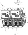
- FIG. 5 is a perspective view illustrating a configuration of freezing apparatus 10A.
- FIG. 6 is a plan view illustrating a configuration of freezing apparatus 10A.
- two freezing modules 1L are coupled with each other in the lateral direction.
- frame members 2L of freezing modules 1L are connected with each other with metal coupling fitting 20 at same height or substantially same height as those of upper section 2Lu and lower section 2Ld on the front and rear sides.
- Metal coupling fittings 20 are fixed to frame members 2L of freezing modules 1L at at least left and right both ends by a publicly known method such as a bolting or welding.
- Freezing modules 1L are coupled with each other with electrical component box 3L and compressor 4L facing forward.
- electrical component boxes 3L are arranged side by side in the lateral direction at the same height (or at substantially the same height) on the front side in freezing apparatus 10A
- compressors 4L are arranged side by side in the lateral direction at the same height (or at substantially the same height) at lower section 2Ld.
- two water-cooling heat exchangers 7a and 7b are arranged side by side in the lateral direction.
- Each of connecting parts (ends) of refrigerant pipes LL of each freezing module 1L extends upward through a rear portion of upper section 2Lu of frame member 2L.
- Refrigerant pipes LL are connected, by connector C5, C6, C7 and C8, with water-cooling heat exchangers 7a and 7b installed in the corresponding freezing module 1L.
- water-cooling heat exchangers 7a and 7b are connected with two headers H arranged in the vertical direction with branched pipe h therebetween.
- refrigerant pipe LL that outputs, to the cooling load side, refrigerant having been subjected to heat exchange at water-cooling heat exchangers 7a and 7b in each freezing module 1L is joined at the coupling part (connector C9), and refrigerant coming back from the cooling load is branched at the coupling part (connector C1) and taken by each freezing module 1L through intake-refrigerant pipe LL.
- shielding plate 8 is formed in an L-shape with an upper wall and a rear wall extending downward from the rear end of the upper wall.
- the upper and rear walls are integrally formed.
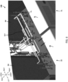
- FIG. 7 is a perspective view illustrating a configuration of freezing apparatus 10B.
- FIG. 8 is a perspective view illustrating a configuration of freezing apparatus 10B in which illustration of the upper wall of heat exchanging module 1H is omitted.
- freezing apparatus 10B includes freezing modules 1S and 1L arranged side by side in the lateral direction in heat exchanging module 1H. Freezing modules 1S and 1L are housed in heat exchanging module 1H in the state where electrical component boxes 3S and 3L and compressors 4S and 4L face forward. As a result, at the front frame where air-cooling heat exchanger 5H is not disposed, electrical component boxes 3S and 3L are arranged side by side in the lateral direction at the same height (or substantially same height) in the upper section, and compressors 4S and 4L are arranged side by side in the lateral direction at the same height (or substantially same height) in the lower section.
- a plurality of connecting parts (ends) of refrigerant pipes LS and LL of freezing modules 1S and 1L extend upward through rear portions of upper sections 2Su and 2Lu of frame members 2S and 2L.
- connecting parts of some refrigerant pipe LS and refrigerant pipe LL are connected by connectors C2, C10, C11 and C12.
- the connecting parts of the remaining refrigerant pipes LS and LL are closed with plugs.
- connector C10 connects refrigerant pipes LS and LL of the inter cooler entrance of compressors 4S and 4L.
- Connector C11 connects refrigerant pipes LS and LL of the inter cooler outlet of compressors 4S and 4L.
- Connector C12 connects refrigerant pipes LS and LL of the air-cooling heat exchanger 5H (gas cooler) outlet.
- the refrigerant pipe that is provided at the side surface, the back surface or the front surface of a lower portion of freezing modules 1S and 1L, is used as a refrigerant pipe to output refrigerant to the cooling load, and therefore refrigerant pipes LS and LL having an ejection port (connection port) on upper sections 2Su and 2Lu of freezing modules 1S and 1L are not used. For this reason, the ejection port (connection port) is closed with a plug.
Landscapes
- Engineering & Computer Science (AREA)
- Chemical & Material Sciences (AREA)
- Combustion & Propulsion (AREA)
- Mechanical Engineering (AREA)
- General Engineering & Computer Science (AREA)
- Physics & Mathematics (AREA)
- Thermal Sciences (AREA)
- Devices That Are Associated With Refrigeration Equipment (AREA)
Claims (6)
- Kühlvorrichtung, umfassend:eine Vielzahl von Kühlmodulen (1S, 1L), die nebeneinander in einer lateralen Richtung angeordnet sind;wobei jedes der Kühlmodule (1S, 1L) umfasst:ein erstes Rahmenelement (2S, 2L), das einen oberen Abschnitt (2Su, 2Lu) und einen unteren Abschnitt (2Sd, 2Ld) aufweist;einen Kältemittelverdichter (4S, 4L), der auf einer Vorderseite in das erste Rahmenelement (2S, 2L) in einem von dem oberen Abschnitt (2Su, 2Lu) und dem unteren Abschnitt (2Sd, 2Ld) eingebaut ist; undeinen Kasten elektrischer Komponenten (3S, 3L), der auf der Vorderseite in das erste Rahmenelement (2S, 2L) in dem anderen von dem oberen Abschnitt (2Su, 2Lu) und dem unteren Abschnitt (2Sd, 2Ld) eingebaut ist, undwobei die Vielzahl von Kühlmodulen (1S, 1L) derart miteinander verbunden sind, dass die Kältemittelverdichter (4S, 4L) der Vielzahl von Kühlmodulen (1S, 1L) nebeneinander in der lateralen Richtung in einer Linie angeordnet sind und dass die Kästen elektrischer Komponenten (3S, 3L) der Vielzahl von Kühlmodulen (1S, 1L) nebeneinander in der lateralen Richtung in einer Linie angeordnet sind.
- Kühlvorrichtung nach Anspruch 1,wobei der Kältemittelverdichter (4S, 4L) in den unteren Abschnitt (2Sd, 2Ld) eingebaut ist; undwobei der Kasten elektrischer Komponenten (3S, 3L) in den oberen Abschnitt (2Su, 2Lu) eingebaut ist.
- Kühlvorrichtung nach Anspruch 2, ferner umfassend ein Abschirmelement (8), das dazu ausgestaltet ist, mindestens einen Teil des Kastens elektrischer Komponenten (3S, 3L) abzuschirmen.
- Kühlvorrichtung nach Anspruch 1 oder 2, wobei eine Vielzahl der Kältemittelverdichter (4S, 4L) nebeneinander in einer lateralen Richtung angeordnet sind.
- Kühlvorrichtung nach einem der Ansprüche 1 bis 3, wobei in dem oberen Abschnitt (2Su, 2Lu) oder dem unteren Abschnitt (2Sd, 2Ld) eine Kältemittelrohrleitung (LS, LL) auf einer Rückseite des ersten Rahmenelements (2S, 2L) vorgesehen ist.
- Kühlvorrichtung nach einem der Ansprüche 1 bis 5, ferner umfassend ein Wärmetauschermodul (1H),
wobei das Wärmetauschermodul (1H) umfasst:ein zweites Rahmenelement (2H), das einen oberen Abschnitt (2Su, 2Lu) und einen unteren Abschnitt (2Sd, 2Ld) aufweist;einen Luftkühlwärmetauscher (5H), der in einem hinteren Rahmenteil, einem linken Rahmenteil und einem rechten Rahmenteil des zweiten Rahmenelements (2H) angeordnet ist, wobei der Luftkühlwärmetauscher (5H) dazu eingerichtet ist, einen Wärmeaustausch zwischen Luft und einem Kältemittel, das von dem Kältemittelverdichter (4S, 4L) zugeführt wird, zu bewirken; undein Luftgebläse (6H), das an einem oberen Teil des zweiten Rahmenelements (2H) vorgesehen und dazu eingerichtet ist, Luft zu dem Luftkühlwärmetauscher (5H) zu schicken, undwobei das Kühlmodul (1S, 1L) in dem zweiten Rahmenelement (2H) angeordnet ist.
Applications Claiming Priority (1)
| Application Number | Priority Date | Filing Date | Title |
|---|---|---|---|
| JP2018171249A JP2020041781A (ja) | 2018-09-13 | 2018-09-13 | 冷却モジュール及び冷却装置 |
Publications (2)
| Publication Number | Publication Date |
|---|---|
| EP3623708A1 EP3623708A1 (de) | 2020-03-18 |
| EP3623708B1 true EP3623708B1 (de) | 2023-05-10 |
Family
ID=67659436
Family Applications (1)
| Application Number | Title | Priority Date | Filing Date |
|---|---|---|---|
| EP19192518.9A Active EP3623708B1 (de) | 2018-09-13 | 2019-08-20 | Kühlmodul und kühlvorrichtung |
Country Status (3)
| Country | Link |
|---|---|
| EP (1) | EP3623708B1 (de) |
| JP (1) | JP2020041781A (de) |
| CN (1) | CN110895080A (de) |
Family Cites Families (13)
| Publication number | Priority date | Publication date | Assignee | Title |
|---|---|---|---|---|
| JPS5710381Y2 (de) * | 1977-03-04 | 1982-02-27 | ||
| JPH03255827A (ja) * | 1990-03-07 | 1991-11-14 | Hitachi Ltd | 空気調和機用室外ユニット |
| CN1309280A (zh) * | 2000-02-17 | 2001-08-22 | 三洋电机株式会社 | 制冷机单元 |
| JP4454595B2 (ja) * | 2006-03-24 | 2010-04-21 | 三洋電機株式会社 | 冷凍装置 |
| KR20100015374A (ko) * | 2007-04-05 | 2010-02-12 | 존슨 컨트롤스 테크놀러지 컴퍼니 | 열교환기 |
| JP4835585B2 (ja) * | 2007-11-28 | 2011-12-14 | 株式会社富士通ゼネラル | 空気調和機の室外機 |
| JP5496182B2 (ja) * | 2009-03-26 | 2014-05-21 | 三菱電機株式会社 | 冷凍機 |
| EP3270068B1 (de) * | 2009-07-28 | 2025-04-16 | Carrier Japan Corporation | Wärmequelleneinheit |
| US20130255932A1 (en) * | 2012-03-30 | 2013-10-03 | Emerson Climate Technologies, Inc. | Heat sink for a condensing unit and method of using same |
| KR20140033728A (ko) * | 2012-09-10 | 2014-03-19 | 대영이앤비 주식회사 | 저온저장고의 실외유니트 |
| JP5805598B2 (ja) * | 2012-09-12 | 2015-11-04 | 三菱電機株式会社 | 冷凍サイクル装置 |
| EP2971982B1 (de) * | 2013-03-15 | 2019-08-14 | Carrier Corporation | Modulare spule für luftgekühlte kühler |
| JP2016125773A (ja) | 2015-01-05 | 2016-07-11 | 三菱重工業株式会社 | 液化ガス用冷却装置 |
-
2018
- 2018-09-13 JP JP2018171249A patent/JP2020041781A/ja active Pending
-
2019
- 2019-08-20 EP EP19192518.9A patent/EP3623708B1/de active Active
- 2019-08-26 CN CN201910788614.3A patent/CN110895080A/zh not_active Withdrawn
Also Published As
| Publication number | Publication date |
|---|---|
| CN110895080A (zh) | 2020-03-20 |
| JP2020041781A (ja) | 2020-03-19 |
| EP3623708A1 (de) | 2020-03-18 |
Similar Documents
| Publication | Publication Date | Title |
|---|---|---|
| EP2740338B1 (de) | Mobile rechenzentrumseinheit mit effizientem kühlmittel | |
| US8944152B2 (en) | Compact evaporator for chillers | |
| US10893633B2 (en) | Method of cooling an electronics cabinet | |
| US7654109B2 (en) | Refrigerating system with economizing cycle | |
| US9459031B2 (en) | Cooling apparatus and cooling system | |
| EP3073813B1 (de) | Gehäuse für eine elektronische vorrichtung und kühlsystem für die elektronische vorrichtung | |
| EP2787291B1 (de) | Ausseneinheit einer klimaanlage | |
| US20110011115A1 (en) | Evaporator air management system for trailer refrigeration | |
| EP3623708B1 (de) | Kühlmodul und kühlvorrichtung | |
| JP2009299993A (ja) | 冷凍装置 | |
| EP3650785B1 (de) | Verkaufskühlvitrine | |
| CN117514921B (zh) | 空调及压缩机 | |
| CN215113331U (zh) | 多冷凝器热泵机组 | |
| CN116916625A (zh) | 热管理系统的电控盒、热管理系统和储能设备 | |
| EP4141354B1 (de) | Relaisvorrichtung und damit ausgestattete klimaanlage | |
| US9939179B2 (en) | Cascading oil distribution system | |
| CN217507471U (zh) | 一种汽车的热管理系统 | |
| CN222507754U (zh) | 一种直冷储能柜 | |
| JP2025523499A (ja) | スイッチギアキャビネットの空調用の冷却装置および対応するスイッチギアキャビネット装置 | |
| CN115773540A (zh) | 一种空调室外机和空调系统 | |
| CN118438848A (zh) | 热管理模块 | |
| CN115751483A (zh) | 一种空调室外机和空调系统 | |
| JP2016080272A (ja) | 冷凍装置 |
Legal Events
| Date | Code | Title | Description |
|---|---|---|---|
| PUAI | Public reference made under article 153(3) epc to a published international application that has entered the european phase |
Free format text: ORIGINAL CODE: 0009012 |
|
| STAA | Information on the status of an ep patent application or granted ep patent |
Free format text: STATUS: THE APPLICATION HAS BEEN PUBLISHED |
|
| AK | Designated contracting states |
Kind code of ref document: A1 Designated state(s): AL AT BE BG CH CY CZ DE DK EE ES FI FR GB GR HR HU IE IS IT LI LT LU LV MC MK MT NL NO PL PT RO RS SE SI SK SM TR |
|
| AX | Request for extension of the european patent |
Extension state: BA ME |
|
| STAA | Information on the status of an ep patent application or granted ep patent |
Free format text: STATUS: REQUEST FOR EXAMINATION WAS MADE |
|
| 17P | Request for examination filed |
Effective date: 20200918 |
|
| RBV | Designated contracting states (corrected) |
Designated state(s): AL AT BE BG CH CY CZ DE DK EE ES FI FR GB GR HR HU IE IS IT LI LT LU LV MC MK MT NL NO PL PT RO RS SE SI SK SM TR |
|
| GRAP | Despatch of communication of intention to grant a patent |
Free format text: ORIGINAL CODE: EPIDOSNIGR1 |
|
| STAA | Information on the status of an ep patent application or granted ep patent |
Free format text: STATUS: GRANT OF PATENT IS INTENDED |
|
| INTG | Intention to grant announced |
Effective date: 20221122 |
|
| GRAS | Grant fee paid |
Free format text: ORIGINAL CODE: EPIDOSNIGR3 |
|
| GRAA | (expected) grant |
Free format text: ORIGINAL CODE: 0009210 |
|
| STAA | Information on the status of an ep patent application or granted ep patent |
Free format text: STATUS: THE PATENT HAS BEEN GRANTED |
|
| AK | Designated contracting states |
Kind code of ref document: B1 Designated state(s): AL AT BE BG CH CY CZ DE DK EE ES FI FR GB GR HR HU IE IS IT LI LT LU LV MC MK MT NL NO PL PT RO RS SE SI SK SM TR |
|
| REG | Reference to a national code |
Ref country code: GB Ref legal event code: FG4D |
|
| REG | Reference to a national code |
Ref country code: AT Ref legal event code: REF Ref document number: 1567003 Country of ref document: AT Kind code of ref document: T Effective date: 20230515 Ref country code: CH Ref legal event code: EP |
|
| REG | Reference to a national code |
Ref country code: DE Ref legal event code: R096 Ref document number: 602019028628 Country of ref document: DE |
|
| REG | Reference to a national code |
Ref country code: IE Ref legal event code: FG4D |
|
| REG | Reference to a national code |
Ref country code: LT Ref legal event code: MG9D |
|
| REG | Reference to a national code |
Ref country code: NL Ref legal event code: MP Effective date: 20230510 |
|
| REG | Reference to a national code |
Ref country code: AT Ref legal event code: MK05 Ref document number: 1567003 Country of ref document: AT Kind code of ref document: T Effective date: 20230510 |
|
| PG25 | Lapsed in a contracting state [announced via postgrant information from national office to epo] |
Ref country code: SE Free format text: LAPSE BECAUSE OF FAILURE TO SUBMIT A TRANSLATION OF THE DESCRIPTION OR TO PAY THE FEE WITHIN THE PRESCRIBED TIME-LIMIT Effective date: 20230510 Ref country code: PT Free format text: LAPSE BECAUSE OF FAILURE TO SUBMIT A TRANSLATION OF THE DESCRIPTION OR TO PAY THE FEE WITHIN THE PRESCRIBED TIME-LIMIT Effective date: 20230911 Ref country code: NO Free format text: LAPSE BECAUSE OF FAILURE TO SUBMIT A TRANSLATION OF THE DESCRIPTION OR TO PAY THE FEE WITHIN THE PRESCRIBED TIME-LIMIT Effective date: 20230810 Ref country code: NL Free format text: LAPSE BECAUSE OF FAILURE TO SUBMIT A TRANSLATION OF THE DESCRIPTION OR TO PAY THE FEE WITHIN THE PRESCRIBED TIME-LIMIT Effective date: 20230510 Ref country code: ES Free format text: LAPSE BECAUSE OF FAILURE TO SUBMIT A TRANSLATION OF THE DESCRIPTION OR TO PAY THE FEE WITHIN THE PRESCRIBED TIME-LIMIT Effective date: 20230510 Ref country code: AT Free format text: LAPSE BECAUSE OF FAILURE TO SUBMIT A TRANSLATION OF THE DESCRIPTION OR TO PAY THE FEE WITHIN THE PRESCRIBED TIME-LIMIT Effective date: 20230510 |
|
| PG25 | Lapsed in a contracting state [announced via postgrant information from national office to epo] |
Ref country code: RS Free format text: LAPSE BECAUSE OF FAILURE TO SUBMIT A TRANSLATION OF THE DESCRIPTION OR TO PAY THE FEE WITHIN THE PRESCRIBED TIME-LIMIT Effective date: 20230510 Ref country code: PL Free format text: LAPSE BECAUSE OF FAILURE TO SUBMIT A TRANSLATION OF THE DESCRIPTION OR TO PAY THE FEE WITHIN THE PRESCRIBED TIME-LIMIT Effective date: 20230510 Ref country code: LV Free format text: LAPSE BECAUSE OF FAILURE TO SUBMIT A TRANSLATION OF THE DESCRIPTION OR TO PAY THE FEE WITHIN THE PRESCRIBED TIME-LIMIT Effective date: 20230510 Ref country code: LT Free format text: LAPSE BECAUSE OF FAILURE TO SUBMIT A TRANSLATION OF THE DESCRIPTION OR TO PAY THE FEE WITHIN THE PRESCRIBED TIME-LIMIT Effective date: 20230510 Ref country code: IS Free format text: LAPSE BECAUSE OF FAILURE TO SUBMIT A TRANSLATION OF THE DESCRIPTION OR TO PAY THE FEE WITHIN THE PRESCRIBED TIME-LIMIT Effective date: 20230910 Ref country code: HR Free format text: LAPSE BECAUSE OF FAILURE TO SUBMIT A TRANSLATION OF THE DESCRIPTION OR TO PAY THE FEE WITHIN THE PRESCRIBED TIME-LIMIT Effective date: 20230510 Ref country code: GR Free format text: LAPSE BECAUSE OF FAILURE TO SUBMIT A TRANSLATION OF THE DESCRIPTION OR TO PAY THE FEE WITHIN THE PRESCRIBED TIME-LIMIT Effective date: 20230811 |
|
| PG25 | Lapsed in a contracting state [announced via postgrant information from national office to epo] |
Ref country code: FI Free format text: LAPSE BECAUSE OF FAILURE TO SUBMIT A TRANSLATION OF THE DESCRIPTION OR TO PAY THE FEE WITHIN THE PRESCRIBED TIME-LIMIT Effective date: 20230510 |
|
| PG25 | Lapsed in a contracting state [announced via postgrant information from national office to epo] |
Ref country code: SK Free format text: LAPSE BECAUSE OF FAILURE TO SUBMIT A TRANSLATION OF THE DESCRIPTION OR TO PAY THE FEE WITHIN THE PRESCRIBED TIME-LIMIT Effective date: 20230510 |
|
| PG25 | Lapsed in a contracting state [announced via postgrant information from national office to epo] |
Ref country code: SM Free format text: LAPSE BECAUSE OF FAILURE TO SUBMIT A TRANSLATION OF THE DESCRIPTION OR TO PAY THE FEE WITHIN THE PRESCRIBED TIME-LIMIT Effective date: 20230510 Ref country code: SK Free format text: LAPSE BECAUSE OF FAILURE TO SUBMIT A TRANSLATION OF THE DESCRIPTION OR TO PAY THE FEE WITHIN THE PRESCRIBED TIME-LIMIT Effective date: 20230510 Ref country code: RO Free format text: LAPSE BECAUSE OF FAILURE TO SUBMIT A TRANSLATION OF THE DESCRIPTION OR TO PAY THE FEE WITHIN THE PRESCRIBED TIME-LIMIT Effective date: 20230510 Ref country code: EE Free format text: LAPSE BECAUSE OF FAILURE TO SUBMIT A TRANSLATION OF THE DESCRIPTION OR TO PAY THE FEE WITHIN THE PRESCRIBED TIME-LIMIT Effective date: 20230510 Ref country code: DK Free format text: LAPSE BECAUSE OF FAILURE TO SUBMIT A TRANSLATION OF THE DESCRIPTION OR TO PAY THE FEE WITHIN THE PRESCRIBED TIME-LIMIT Effective date: 20230510 Ref country code: CZ Free format text: LAPSE BECAUSE OF FAILURE TO SUBMIT A TRANSLATION OF THE DESCRIPTION OR TO PAY THE FEE WITHIN THE PRESCRIBED TIME-LIMIT Effective date: 20230510 |
|
| REG | Reference to a national code |
Ref country code: DE Ref legal event code: R097 Ref document number: 602019028628 Country of ref document: DE |
|
| PG25 | Lapsed in a contracting state [announced via postgrant information from national office to epo] |
Ref country code: MC Free format text: LAPSE BECAUSE OF FAILURE TO SUBMIT A TRANSLATION OF THE DESCRIPTION OR TO PAY THE FEE WITHIN THE PRESCRIBED TIME-LIMIT Effective date: 20230510 |
|
| PLBE | No opposition filed within time limit |
Free format text: ORIGINAL CODE: 0009261 |
|
| STAA | Information on the status of an ep patent application or granted ep patent |
Free format text: STATUS: NO OPPOSITION FILED WITHIN TIME LIMIT |
|
| REG | Reference to a national code |
Ref country code: CH Ref legal event code: PL |
|
| PG25 | Lapsed in a contracting state [announced via postgrant information from national office to epo] |
Ref country code: MC Free format text: LAPSE BECAUSE OF FAILURE TO SUBMIT A TRANSLATION OF THE DESCRIPTION OR TO PAY THE FEE WITHIN THE PRESCRIBED TIME-LIMIT Effective date: 20230510 |
|
| PG25 | Lapsed in a contracting state [announced via postgrant information from national office to epo] |
Ref country code: LU Free format text: LAPSE BECAUSE OF NON-PAYMENT OF DUE FEES Effective date: 20230820 |
|
| 26N | No opposition filed |
Effective date: 20240213 |
|
| PG25 | Lapsed in a contracting state [announced via postgrant information from national office to epo] |
Ref country code: LU Free format text: LAPSE BECAUSE OF NON-PAYMENT OF DUE FEES Effective date: 20230820 Ref country code: CH Free format text: LAPSE BECAUSE OF NON-PAYMENT OF DUE FEES Effective date: 20230831 |
|
| PG25 | Lapsed in a contracting state [announced via postgrant information from national office to epo] |
Ref country code: SI Free format text: LAPSE BECAUSE OF FAILURE TO SUBMIT A TRANSLATION OF THE DESCRIPTION OR TO PAY THE FEE WITHIN THE PRESCRIBED TIME-LIMIT Effective date: 20230510 |
|
| REG | Reference to a national code |
Ref country code: BE Ref legal event code: MM Effective date: 20230831 |
|
| REG | Reference to a national code |
Ref country code: IE Ref legal event code: MM4A |
|
| PG25 | Lapsed in a contracting state [announced via postgrant information from national office to epo] |
Ref country code: SI Free format text: LAPSE BECAUSE OF FAILURE TO SUBMIT A TRANSLATION OF THE DESCRIPTION OR TO PAY THE FEE WITHIN THE PRESCRIBED TIME-LIMIT Effective date: 20230510 Ref country code: IT Free format text: LAPSE BECAUSE OF FAILURE TO SUBMIT A TRANSLATION OF THE DESCRIPTION OR TO PAY THE FEE WITHIN THE PRESCRIBED TIME-LIMIT Effective date: 20230510 |
|
| PG25 | Lapsed in a contracting state [announced via postgrant information from national office to epo] |
Ref country code: IE Free format text: LAPSE BECAUSE OF NON-PAYMENT OF DUE FEES Effective date: 20230820 |
|
| PG25 | Lapsed in a contracting state [announced via postgrant information from national office to epo] |
Ref country code: IE Free format text: LAPSE BECAUSE OF NON-PAYMENT OF DUE FEES Effective date: 20230820 |
|
| PG25 | Lapsed in a contracting state [announced via postgrant information from national office to epo] |
Ref country code: BE Free format text: LAPSE BECAUSE OF NON-PAYMENT OF DUE FEES Effective date: 20230831 |
|
| PG25 | Lapsed in a contracting state [announced via postgrant information from national office to epo] |
Ref country code: BG Free format text: LAPSE BECAUSE OF FAILURE TO SUBMIT A TRANSLATION OF THE DESCRIPTION OR TO PAY THE FEE WITHIN THE PRESCRIBED TIME-LIMIT Effective date: 20230510 |
|
| PG25 | Lapsed in a contracting state [announced via postgrant information from national office to epo] |
Ref country code: BG Free format text: LAPSE BECAUSE OF FAILURE TO SUBMIT A TRANSLATION OF THE DESCRIPTION OR TO PAY THE FEE WITHIN THE PRESCRIBED TIME-LIMIT Effective date: 20230510 |
|
| PG25 | Lapsed in a contracting state [announced via postgrant information from national office to epo] |
Ref country code: CY Free format text: LAPSE BECAUSE OF FAILURE TO SUBMIT A TRANSLATION OF THE DESCRIPTION OR TO PAY THE FEE WITHIN THE PRESCRIBED TIME-LIMIT; INVALID AB INITIO Effective date: 20190820 |
|
| PG25 | Lapsed in a contracting state [announced via postgrant information from national office to epo] |
Ref country code: HU Free format text: LAPSE BECAUSE OF FAILURE TO SUBMIT A TRANSLATION OF THE DESCRIPTION OR TO PAY THE FEE WITHIN THE PRESCRIBED TIME-LIMIT; INVALID AB INITIO Effective date: 20190820 |
|
| PGFP | Annual fee paid to national office [announced via postgrant information from national office to epo] |
Ref country code: DE Payment date: 20250820 Year of fee payment: 7 |
|
| PGFP | Annual fee paid to national office [announced via postgrant information from national office to epo] |
Ref country code: GB Payment date: 20250820 Year of fee payment: 7 |
|
| PGFP | Annual fee paid to national office [announced via postgrant information from national office to epo] |
Ref country code: FR Payment date: 20250828 Year of fee payment: 7 |
|
| PG25 | Lapsed in a contracting state [announced via postgrant information from national office to epo] |
Ref country code: TR Free format text: LAPSE BECAUSE OF FAILURE TO SUBMIT A TRANSLATION OF THE DESCRIPTION OR TO PAY THE FEE WITHIN THE PRESCRIBED TIME-LIMIT Effective date: 20230510 |