EP3623727A1 - Pompe à chaleur - Google Patents
Pompe à chaleur Download PDFInfo
- Publication number
- EP3623727A1 EP3623727A1 EP19196374.3A EP19196374A EP3623727A1 EP 3623727 A1 EP3623727 A1 EP 3623727A1 EP 19196374 A EP19196374 A EP 19196374A EP 3623727 A1 EP3623727 A1 EP 3623727A1
- Authority
- EP
- European Patent Office
- Prior art keywords
- vapour
- pressure
- booster
- compressor
- temperature
- Prior art date
- Legal status (The legal status is an assumption and is not a legal conclusion. Google has not performed a legal analysis and makes no representation as to the accuracy of the status listed.)
- Withdrawn
Links
- 238000012804 iterative process Methods 0.000 claims abstract description 8
- 238000012546 transfer Methods 0.000 claims description 12
- 238000010438 heat treatment Methods 0.000 claims description 10
- 238000009434 installation Methods 0.000 claims description 7
- 239000007788 liquid Substances 0.000 description 7
- 238000001816 cooling Methods 0.000 description 6
- 238000012549 training Methods 0.000 description 4
- XLYOFNOQVPJJNP-UHFFFAOYSA-N water Substances O XLYOFNOQVPJJNP-UHFFFAOYSA-N 0.000 description 4
- 238000010586 diagram Methods 0.000 description 2
- 238000002347 injection Methods 0.000 description 2
- 239000007924 injection Substances 0.000 description 2
- 238000000034 method Methods 0.000 description 2
- 241001465754 Metazoa Species 0.000 description 1
- 239000003570 air Substances 0.000 description 1
- 239000012080 ambient air Substances 0.000 description 1
- 230000003247 decreasing effect Effects 0.000 description 1
- 230000001419 dependent effect Effects 0.000 description 1
- 230000000694 effects Effects 0.000 description 1
- 230000007613 environmental effect Effects 0.000 description 1
- 238000013021 overheating Methods 0.000 description 1
- 239000008399 tap water Substances 0.000 description 1
- 235000020679 tap water Nutrition 0.000 description 1
- 238000012360 testing method Methods 0.000 description 1
Images


Classifications
-
- F—MECHANICAL ENGINEERING; LIGHTING; HEATING; WEAPONS; BLASTING
- F25—REFRIGERATION OR COOLING; COMBINED HEATING AND REFRIGERATION SYSTEMS; HEAT PUMP SYSTEMS; MANUFACTURE OR STORAGE OF ICE; LIQUEFACTION SOLIDIFICATION OF GASES
- F25B—REFRIGERATION MACHINES, PLANTS OR SYSTEMS; COMBINED HEATING AND REFRIGERATION SYSTEMS; HEAT PUMP SYSTEMS
- F25B49/00—Arrangement or mounting of control or safety devices
- F25B49/02—Arrangement or mounting of control or safety devices for compression type machines, plants or systems
- F25B49/027—Condenser control arrangements
-
- F—MECHANICAL ENGINEERING; LIGHTING; HEATING; WEAPONS; BLASTING
- F25—REFRIGERATION OR COOLING; COMBINED HEATING AND REFRIGERATION SYSTEMS; HEAT PUMP SYSTEMS; MANUFACTURE OR STORAGE OF ICE; LIQUEFACTION SOLIDIFICATION OF GASES
- F25B—REFRIGERATION MACHINES, PLANTS OR SYSTEMS; COMBINED HEATING AND REFRIGERATION SYSTEMS; HEAT PUMP SYSTEMS
- F25B2339/00—Details of evaporators; Details of condensers
- F25B2339/04—Details of condensers
- F25B2339/047—Water-cooled condensers
-
- F—MECHANICAL ENGINEERING; LIGHTING; HEATING; WEAPONS; BLASTING
- F25—REFRIGERATION OR COOLING; COMBINED HEATING AND REFRIGERATION SYSTEMS; HEAT PUMP SYSTEMS; MANUFACTURE OR STORAGE OF ICE; LIQUEFACTION SOLIDIFICATION OF GASES
- F25B—REFRIGERATION MACHINES, PLANTS OR SYSTEMS; COMBINED HEATING AND REFRIGERATION SYSTEMS; HEAT PUMP SYSTEMS
- F25B2400/00—General features or devices for refrigeration machines, plants or systems, combined heating and refrigeration systems or heat-pump systems, i.e. not limited to a particular subgroup of F25B
- F25B2400/13—Economisers
-
- F—MECHANICAL ENGINEERING; LIGHTING; HEATING; WEAPONS; BLASTING
- F25—REFRIGERATION OR COOLING; COMBINED HEATING AND REFRIGERATION SYSTEMS; HEAT PUMP SYSTEMS; MANUFACTURE OR STORAGE OF ICE; LIQUEFACTION SOLIDIFICATION OF GASES
- F25B—REFRIGERATION MACHINES, PLANTS OR SYSTEMS; COMBINED HEATING AND REFRIGERATION SYSTEMS; HEAT PUMP SYSTEMS
- F25B2600/00—Control issues
- F25B2600/25—Control of valves
- F25B2600/2509—Economiser valves
-
- F—MECHANICAL ENGINEERING; LIGHTING; HEATING; WEAPONS; BLASTING
- F25—REFRIGERATION OR COOLING; COMBINED HEATING AND REFRIGERATION SYSTEMS; HEAT PUMP SYSTEMS; MANUFACTURE OR STORAGE OF ICE; LIQUEFACTION SOLIDIFICATION OF GASES
- F25B—REFRIGERATION MACHINES, PLANTS OR SYSTEMS; COMBINED HEATING AND REFRIGERATION SYSTEMS; HEAT PUMP SYSTEMS
- F25B2700/00—Sensing or detecting of parameters; Sensors therefor
- F25B2700/19—Pressures
- F25B2700/193—Pressures of the compressor
- F25B2700/1931—Discharge pressures
-
- F—MECHANICAL ENGINEERING; LIGHTING; HEATING; WEAPONS; BLASTING
- F25—REFRIGERATION OR COOLING; COMBINED HEATING AND REFRIGERATION SYSTEMS; HEAT PUMP SYSTEMS; MANUFACTURE OR STORAGE OF ICE; LIQUEFACTION SOLIDIFICATION OF GASES
- F25B—REFRIGERATION MACHINES, PLANTS OR SYSTEMS; COMBINED HEATING AND REFRIGERATION SYSTEMS; HEAT PUMP SYSTEMS
- F25B2700/00—Sensing or detecting of parameters; Sensors therefor
- F25B2700/21—Temperatures
- F25B2700/2115—Temperatures of a compressor or the drive means therefor
- F25B2700/21152—Temperatures of a compressor or the drive means therefor at the discharge side of the compressor
Definitions
- the invention relates to a device which is intended and arranged as a heat pump system as a heat source for, for example, a central heating system or other installation.
- Heat pump systems are generally known (see, for example, https://en.wikipedia.org/wiki/Heat_pump). There is now a renewed interest in heat pump systems due to environmental requirements and energy needs.
- the object of the present invention is to provide a heat pump system in which substantially higher temperatures can be achieved than up till now are customary.
- the present invention is based on the insight that in particular the vapour compressor of the installation can be loaded considerably more heavily than when the installation is started. But also during operation, the load capacity of the compressor can be trained, as it were, or "stretched” if, like physical training for humans or animals, the load is increased, for example, stepwise, by applying "stretch/relax" control of the system, whereby the system is able to deliver a substantially higher output, resulting in a higher efficiency and a higher water temperature when the heat pump system is used as a heat source for a central heating system.
- a device intended and arranged as a heat pump system serving as a heat source for, for example, a central heating system or other installation, comprising a circulation channel of which a supply section is arranged for transporting a heat transfer medium in vapour form, hereinafter referred to as vapour, from the outlet of an evaporator to the inlet of a condenser, by means of a vapour compressor, which is adapted to draw in the vapour from the evaporator through a low-pressure portion of the supply section of the circulation channel and through a low-pressure inlet, and to compress the vapour from a low to a high pressure, and to supply the pressurized vapour to the condenser through a high-pressure portion of the supply section of the circulation channel.
- vapour a heat transfer medium in vapour form
- the circulation channel also comprises a return section, which is adapted for transporting the heat medium from the outlet of the condenser to the inlet of the evaporator through an expansion member (e.g. an expansion valve, throttle valve, optionally turbine), which is arranged to reduce the pressure of the heat transfer medium originating from the condenser outlet and thereby to flash/expand the heat medium.
- an expansion member e.g. an expansion valve, throttle valve, optionally turbine
- a primary circuit of a booster heat exchanger comprising a primary and a secondary circuit is included in the return section of the circulation channel, preferably in the high-pressure section of the return section of the circulation channel, i.e. between the outlet of the condenser and the expansion member.
- the secondary circuit of the booster heat exchanger is included in a booster circuit between the return section of the circulation channel, on the side of the inlet or outlet of the primary circuit (i.e. in cocurrent or counter-current configuration), and a booster vapour inlet of either the aforementioned vapour compressor or another vapour compressor, which (in both cases) is connected with its high-pressure side to the high-pressure portion of the supply section of the circulation channel.
- a control member is provided, such as a microprocessor or microcontroller, and a temperature and/or pressure sensor for measuring the temperature or pressure in the aforementioned vapour compressor, and a control valve controllable by the control member and included in the booster circuit. During operation, the sensors transmit the measured temperature and pressure to the control member.
- the control member is arranged or programmed in such a way that, in an iterative process, the supply of vapour through the booster circuit to the booster vapour inlet is stopped or reduced by means of the control valve as soon as the temperature and/or the pressure in the vapour compressor reaches an extreme limit value for the temperature value or the pressure value in the vapour compressor, after which the control member, after a time t determined by the control member, by means of the control valve, restores the supply of vapour through the booster circuit to the booster vapour inlet, after which the iterative process is repeated as long as required by the heat demand of the device.
- the aforementioned vapour compressor is of the spiral compressor type (scroll compressor), comprising a low-pressure inlet, a high-pressure outlet and a booster connection, wherein the outlet of the secondary circuit of the booster heat exchanger is connected to the booster connection of the scroll compressor, which is connected with its high-pressure side to the high-pressure portion of the supply section of the circulation channel.
- spiral compressor spiral compressor
- the vapour compressor is of a type without a booster connection, wherein the outlet of the secondary circuit of the booster heat exchanger is connected to an (additional) auxiliary or booster compressor which, like the aforementioned vapour compressor, is connected at its high-pressure side to the high-pressure portion of the supply section of the circulation channel.
- the compressor used is of the scroll compressor type, which has an (additional) connection for the injection of a vapour (vapour or gaseous heat transfer medium) having an already elevated temperature.
- a vapour vapour or gaseous heat transfer medium
- the high-temperature vapour obtained by converting the high-pressure liquid recirculated from the condenser back to vapour by means of an expansion valve, is injected into the secondary circuit of the booster heat exchanger (also called "economizer").
- the booster heat exchanger also called "economizer”
- a vapour with a high temperature is obtained, which subsequently if necessary (depending on the heat demand) is injected into the compressor through the (additional) booster connection on the compressor, whereby an extra high outlet temperature can be achieved on the high-pressure side of the compressor.
- the supply of hot vapour to the booster connection of the compressor is carefully controlled by the microcomputer, which accurately controls the temperature in the compressor by means of data obtained by the various sensors.
- the temperature sensor records the (head) temperature of the compressor
- the pressure sensor of the compressor records the pressure values prevailing within the compressor, and sends the values to the microcomputer. With these values, the microcomputer calculates if and when cooling is required. If the temperature in the compressor becomes too high or if the pressure dependent on this temperature becomes too high, the microcomputer will close the control valve (solenoid valve) in the booster circuit.
- the high-pressure liquid is sent directly and in full to the evaporator, so that only a low-pressure vapour having a low temperature is injected into the compressor.
- the compressor never gets too hot and never operates with a too high pressure.
- the pressure will become correspondingly higher.
- the high temperature vapour in the compressor, and consequently the compressor itself is cooled back (just) in time (by interrupting or reducing the booster flow at the booster inlet of the compressor).
- the temperature in the condenser is gradually increased until, as tests at working conditions have shown, a temperature of 115 °C instead of about 55 °C, as has been common practice until now, without using the training process according to the invention.
- the high temperatures in the condenser can only be achieved by operating at high pressures and by injecting hot vapour.
- high vapour temperatures result in high temperatures and high pressures in the compressor.
- a compressor is able to temporarily handle very high pressures but not for a long time. So, in order to be able to reach high temperatures in a condenser, the time during which the compressor operates under high pressure will have to be monitored, taking the temperature into account. The higher the pressure and temperature in the compressor, the shorter the compressor will be able to perform before the compressor will fail due to (too) long operation at high pressure.
- the microcomputer calculates very accurately the length of time that can be used to achieve a high condenser temperature, and switches to the cooling mode for the compressor just in time (shutting down or reducing the hot booster stream through the booster circuit). It is important to provide the cooling mode with a time period, that is just long enough to allow the compressor to cool down sufficiently, but that simultaneously ensures that the temperature in the system is kept high, namely by choosing the compressor's cooling time as short as possible.
- the following operating conditions are essential and crucial: the higher the temperature in the system, the more often the compressor will have to cool down. During operation, this is also observed, because the steps are getting shorter, while the temperature in the system is going up.
- the compressor when the system is at the desired temperature, the compressor will switch off completely. But to save energy, if there is still a heat demand, the microcomputer will continue to monitor the temperature of the system and when this temperature drops to a temperature difference with a delta T of more than 10 °C (of the central heating system water temperature) with respect to the set desired temperature, the compressor will restart to compensate for the decreased temperature and restore the desired temperature.
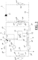
- Figures 1 and 2 both show a schematic representation of an exemplary embodiment of a device 1 according to the invention, which is intended and arranged as a heat pump system, serving as a heat source for, for example, a central heating system 2 or other installation.
- the device i.e. the actual heat pump system, comprises a circulation channel 3 of which a supply section 3a-b (see also flow direction arrows 4) is adapted for transporting a heat transfer medium in vapour form, hereinafter referred to as vapour, from the outlet 5b of an evaporator 5 to the inlet 6a of a condenser 6, by means of a vapour compressor 7, which is adapted to draw in a vapour from a low-pressure portion 3a of the supply section 3a-b of the circulation channel 3 through a low-pressure inlet 7a, and to compress the vapour from a low to a high pressure, and to press (pump) the high-pressure vapour through a high-pressure portion 3b of the supply section of the circulation channel 3 to the inlet 6a of the condenser 6.
- vapour a heat transfer medium in vapour form
- the circulation channel 3 comprises a return section 3c-d, which is adapted to transport the heat transfer medium from the outlet 6b of the condenser 6 to the inlet 5a of the evaporator 5 through an expansion member 8, which is adapted to reduce the pressure of the heat transfer medium from outlet 6b of the condenser 6 by means of expansion of the heat transfer medium.
- the secondary circuit 9b is included in a booster circuit 10 between on the one hand the high-pressure portion 3c of the return section 3c-d of the circulation channel 3 and, on the other hand, a booster vapour inlet 7c, 19a of either the aforementioned vapour compressor 7, as represented in figure 1 , or another (auxiliary or booster) vapour compressor 19, as represented in figure 2 , which (in both embodiments) are connected with their high-pressure side 7b, 19b to the high-pressure portion 3b of the supply section 3a-b of the circulation channel 3.
- the secondary circuit 9b of the booster heat exchanger 9 is connected with the high-pressure portion 3b of the supply section 3a-b of the circulation channel 3 through an expansion/control valve 12, hereinafter referred to as control valve, which is controllable from a control member 11.
- control member 11 for example a microprocessor or microcontroller
- control valve 12 which is included in the booster circuit 10 and is controlled by the control member 11
- a temperature sensor 13 and a pressure sensor 14 are provided for measuring the temperature and the pressure within the vapour compressor 7.
- the sensors transmit the measured temperature and pressure to the control member 11 during operation of the device.
- the control member 11 is arranged or programmed in such a way that, in an iterative process (see Figure 3 ), the supply of the vapour through the booster circuit 10 to the booster vapour inlet 7c by means of the control valve 12 is stopped or reduced as soon as the temperature and/or the pressure within the vapour compressor reaches an extreme limit value T max or p max for the temperature or pressure value within the vapour compressor.
- T max or p max for the temperature or pressure value within the vapour compressor.
- Heat transport therefore takes place in and by means of device 1 from a heat source with a low temperature, for example ambient air, which is supplied to the evaporator 5; for example by a fan (not shown) (the evaporator 5 thus forms an air/liquid heat exchanger).
- a heat source with a low temperature, for example ambient air
- the evaporator 5 thus forms an air/liquid heat exchanger.
- the condenser 6 forms the primary circuit of (for example) a liquid/liquid heat exchanger, of which the secondary circuit 6c is included as a heat source (with a high temperature) in the circulation circuit 16 of the aforementioned central heating system 2, in which the heat transfer medium (usually water) is circulated through radiators 18 by means of a circulation pump 17, whereby the heat 15c is transferred to the environment of the radiators.
- the secondary circuit 6c of the liquid/liquid heat exchanger as is usual in every modern heating installation/system, is used for heating tap water, for example by means of a switch valve (not shown).
- FIG. 1 shows, as stated, an exemplary embodiment in which the vapour compressor 7 is of the spiral compressor type (scroll compressor), comprising a low-pressure inlet 7a, a high-pressure outlet 7b and a booster connection (booster vapour inlet 7c), wherein the secondary circuit 9b of the booster heat exchanger 9 has its outlet 9c connected to the booster connection 7c of the spiral compressor 7, which is connected with its high-pressure side 7b to the high-pressure portion 3b of the supply section 3a-b of the circulation channel 3.
- the vapour compressor 7 is of the spiral compressor type (scroll compressor), comprising a low-pressure inlet 7a, a high-pressure outlet 7b and a booster connection (booster vapour inlet 7c), wherein the secondary circuit 9b of the booster heat exchanger 9 has its outlet 9c connected to the booster connection 7c of the spiral compressor 7, which is connected with its high-pressure side 7b to the high-pressure portion 3b of the supply section 3a-b of the circulation channel 3.
- FIG. 2 shows an exemplary embodiment wherein the vapour compressor 7' is of a type without booster connection (booster vapour inlet), wherein the secondary circuit 9b of the booster heat exchanger 9 at its outlet 9c is connected to the booster vapour inlet 19a of an auxiliary or booster compressor 19 which, like the vapour compressor 7', has its high-pressure side 19b connected to the high-pressure portion 3b of the supply section 3a-b of the circulation channel 3.
- booster vapour inlet booster connection
- both compressors 7' and 19 can be jointly assembled if desired, so that both compressors will assume/adopt approximately the same temperature by means of their joint housing. Therefore, both compressors are cooled by means of the inflow, through the low-pressure compressor inlet 7a, of the relatively cold heat transfer medium from the outlet 5b of the evaporator 5.
- FIG 3 shows an example of a "step diagram", in which the temperature line curve 20 of the compressor 7 is plotted as a function of time for a device according to the invention with a substantial heat demand. Furthermore, the associated temperature line curve 21 is shown of the heat transfer medium (usually water) within the central heating system 2.
- the heat transfer medium usually water
Landscapes
- Engineering & Computer Science (AREA)
- Physics & Mathematics (AREA)
- Mechanical Engineering (AREA)
- Thermal Sciences (AREA)
- General Engineering & Computer Science (AREA)
- Heat-Pump Type And Storage Water Heaters (AREA)
Applications Claiming Priority (1)
| Application Number | Priority Date | Filing Date | Title |
|---|---|---|---|
| NL1042999A NL1042999B9 (nl) | 2018-09-14 | 2018-09-14 | Inrichting, bestemd en ingericht als warmtepompsysteem met boostercircuit als warmtebron voor bijvoorbeeld een cv- of andere installatie |
Publications (1)
| Publication Number | Publication Date |
|---|---|
| EP3623727A1 true EP3623727A1 (fr) | 2020-03-18 |
Family
ID=64172541
Family Applications (1)
| Application Number | Title | Priority Date | Filing Date |
|---|---|---|---|
| EP19196374.3A Withdrawn EP3623727A1 (fr) | 2018-09-14 | 2019-09-10 | Pompe à chaleur |
Country Status (2)
| Country | Link |
|---|---|
| EP (1) | EP3623727A1 (fr) |
| NL (1) | NL1042999B9 (fr) |
Cited By (1)
| Publication number | Priority date | Publication date | Assignee | Title |
|---|---|---|---|---|
| CN114484935A (zh) * | 2021-12-31 | 2022-05-13 | 青岛海尔空调电子有限公司 | 热泵机组及其控制方法和控制装置 |
Citations (6)
| Publication number | Priority date | Publication date | Assignee | Title |
|---|---|---|---|---|
| JPS5777863U (fr) * | 1981-10-15 | 1982-05-14 | ||
| JPS61165555A (ja) * | 1985-01-11 | 1986-07-26 | 株式会社デンソー | 冷凍冷房装置 |
| US20080098754A1 (en) * | 2006-10-26 | 2008-05-01 | Johnson Controls Technology Company | Economized refrigeration system |
| US20080184733A1 (en) * | 2007-02-05 | 2008-08-07 | Tecumseh Products Company | Scroll compressor with refrigerant injection system |
| US20100095700A1 (en) * | 2006-12-29 | 2010-04-22 | Carrier Corporation | Economizer Heat Exchanger |
| WO2011045522A1 (fr) * | 2009-10-13 | 2011-04-21 | Danfoss Commercial Compressors | Système de réfrigération et unité de pompe à chaleur comprenant un tel système |
-
2018
- 2018-09-14 NL NL1042999A patent/NL1042999B9/nl not_active IP Right Cessation
-
2019
- 2019-09-10 EP EP19196374.3A patent/EP3623727A1/fr not_active Withdrawn
Patent Citations (6)
| Publication number | Priority date | Publication date | Assignee | Title |
|---|---|---|---|---|
| JPS5777863U (fr) * | 1981-10-15 | 1982-05-14 | ||
| JPS61165555A (ja) * | 1985-01-11 | 1986-07-26 | 株式会社デンソー | 冷凍冷房装置 |
| US20080098754A1 (en) * | 2006-10-26 | 2008-05-01 | Johnson Controls Technology Company | Economized refrigeration system |
| US20100095700A1 (en) * | 2006-12-29 | 2010-04-22 | Carrier Corporation | Economizer Heat Exchanger |
| US20080184733A1 (en) * | 2007-02-05 | 2008-08-07 | Tecumseh Products Company | Scroll compressor with refrigerant injection system |
| WO2011045522A1 (fr) * | 2009-10-13 | 2011-04-21 | Danfoss Commercial Compressors | Système de réfrigération et unité de pompe à chaleur comprenant un tel système |
Cited By (2)
| Publication number | Priority date | Publication date | Assignee | Title |
|---|---|---|---|---|
| CN114484935A (zh) * | 2021-12-31 | 2022-05-13 | 青岛海尔空调电子有限公司 | 热泵机组及其控制方法和控制装置 |
| CN114484935B (zh) * | 2021-12-31 | 2023-09-26 | 青岛海尔空调电子有限公司 | 热泵机组及其控制方法和控制装置 |
Also Published As
| Publication number | Publication date |
|---|---|
| NL1042999B9 (nl) | 2020-07-23 |
| NL1042999B1 (nl) | 2020-05-29 |
Similar Documents
| Publication | Publication Date | Title |
|---|---|---|
| US11279205B2 (en) | Method for operating a coolant circuit and vehicle air-conditioning system | |
| US9157667B2 (en) | Heat pump-type heating device | |
| US20130019617A1 (en) | Defrost for transcritical vapor compression system | |
| TW522212B (en) | Method and system for defrost control on reversible heat pumps | |
| US20190360731A1 (en) | Refrigerant transfer control in multi mode air conditioner with hot water generator | |
| US7127905B2 (en) | Vapor compression system startup method | |
| EP3575712B1 (fr) | Système de refroidissement | |
| JP4337880B2 (ja) | ヒートポンプ式給湯器 | |
| US20150052917A1 (en) | Constant temperature liquid circulation apparatus and temperature adjustment method for constant temperature liquid | |
| CN110044005A (zh) | 一种空调控制方法、装置及空调 | |
| EP3623727A1 (fr) | Pompe à chaleur | |
| CN111595586A (zh) | 一种航空发动机燃油泵低温试验系统及实验方法 | |
| CN111854203A (zh) | 一种冷柜设备、制冷系统及其控制方法 | |
| CN211740627U (zh) | 一种航空发动机燃油泵低温试验系统 | |
| EP3564600B1 (fr) | Système de refroidissement et procédé d'operation | |
| US11708981B2 (en) | High-pressure re-start control algorithm for microchannel condenser with reheat coil | |
| TWI576549B (zh) | Thermostatic liquid circulation device and temperature adjustment method of constant temperature liquid | |
| CN111854206B (zh) | 一种冷柜设备、制冷系统及其控制方法 | |
| JP2011257094A (ja) | 冷凍サイクル装置 | |
| JP2637304B2 (ja) | 多室形空気調和装置 | |
| CN119512268B (zh) | 一种温度控制系统及温度控制方法 | |
| JPWO2021156964A5 (fr) | ||
| EP3850280B1 (fr) | Unité frigorifique de transport faisant appel à la chaleur perdue du moteur pour le dégivrage | |
| US20250237411A1 (en) | Expansion system and heat pump incorporating the same | |
| CN117366665A (zh) | 空调系统及其控制方法 |
Legal Events
| Date | Code | Title | Description |
|---|---|---|---|
| PUAI | Public reference made under article 153(3) epc to a published international application that has entered the european phase |
Free format text: ORIGINAL CODE: 0009012 |
|
| STAA | Information on the status of an ep patent application or granted ep patent |
Free format text: STATUS: THE APPLICATION HAS BEEN PUBLISHED |
|
| AK | Designated contracting states |
Kind code of ref document: A1 Designated state(s): AL AT BE BG CH CY CZ DE DK EE ES FI FR GB GR HR HU IE IS IT LI LT LU LV MC MK MT NL NO PL PT RO RS SE SI SK SM TR |
|
| AX | Request for extension of the european patent |
Extension state: BA ME |
|
| STAA | Information on the status of an ep patent application or granted ep patent |
Free format text: STATUS: REQUEST FOR EXAMINATION WAS MADE |
|
| 17P | Request for examination filed |
Effective date: 20200918 |
|
| RBV | Designated contracting states (corrected) |
Designated state(s): AL AT BE BG CH CY CZ DE DK EE ES FI FR GB GR HR HU IE IS IT LI LT LU LV MC MK MT NL NO PL PT RO RS SE SI SK SM TR |
|
| STAA | Information on the status of an ep patent application or granted ep patent |
Free format text: STATUS: EXAMINATION IS IN PROGRESS |
|
| RIC1 | Information provided on ipc code assigned before grant |
Ipc: F25B 49/02 20060101AFI20210330BHEP |
|
| 17Q | First examination report despatched |
Effective date: 20210426 |
|
| STAA | Information on the status of an ep patent application or granted ep patent |
Free format text: STATUS: THE APPLICATION IS DEEMED TO BE WITHDRAWN |
|
| 18D | Application deemed to be withdrawn |
Effective date: 20210707 |