EP3623767A1 - Arbre et procédé de fabrication d'un arbre, rotor et machine électrique - Google Patents
Arbre et procédé de fabrication d'un arbre, rotor et machine électrique Download PDFInfo
- Publication number
- EP3623767A1 EP3623767A1 EP18194806.8A EP18194806A EP3623767A1 EP 3623767 A1 EP3623767 A1 EP 3623767A1 EP 18194806 A EP18194806 A EP 18194806A EP 3623767 A1 EP3623767 A1 EP 3623767A1
- Authority
- EP
- European Patent Office
- Prior art keywords
- shaft
- layer
- base body
- buffer layer
- measuring
- Prior art date
- Legal status (The legal status is an assumption and is not a legal conclusion. Google has not performed a legal analysis and makes no representation as to the accuracy of the status listed.)
- Withdrawn
Links
- 238000004519 manufacturing process Methods 0.000 title claims description 6
- 238000000034 method Methods 0.000 claims abstract description 39
- 238000003466 welding Methods 0.000 claims abstract description 39
- 239000000463 material Substances 0.000 claims abstract description 29
- 230000005291 magnetic effect Effects 0.000 claims abstract description 21
- 229910000831 Steel Inorganic materials 0.000 claims description 19
- 239000010959 steel Substances 0.000 claims description 19
- VNNRSPGTAMTISX-UHFFFAOYSA-N chromium nickel Chemical compound [Cr].[Ni] VNNRSPGTAMTISX-UHFFFAOYSA-N 0.000 claims description 10
- 238000003754 machining Methods 0.000 claims description 9
- 238000005259 measurement Methods 0.000 claims description 4
- 230000005294 ferromagnetic effect Effects 0.000 claims description 3
- 238000012545 processing Methods 0.000 claims description 3
- PXHVJJICTQNCMI-UHFFFAOYSA-N Nickel Chemical compound [Ni] PXHVJJICTQNCMI-UHFFFAOYSA-N 0.000 description 11
- 229910052799 carbon Inorganic materials 0.000 description 8
- OKTJSMMVPCPJKN-UHFFFAOYSA-N Carbon Chemical compound [C] OKTJSMMVPCPJKN-UHFFFAOYSA-N 0.000 description 7
- 229910052759 nickel Inorganic materials 0.000 description 7
- 238000005476 soldering Methods 0.000 description 5
- 239000007788 liquid Substances 0.000 description 4
- VYZAMTAEIAYCRO-UHFFFAOYSA-N Chromium Chemical compound [Cr] VYZAMTAEIAYCRO-UHFFFAOYSA-N 0.000 description 3
- PWHULOQIROXLJO-UHFFFAOYSA-N Manganese Chemical compound [Mn] PWHULOQIROXLJO-UHFFFAOYSA-N 0.000 description 3
- 229910045601 alloy Inorganic materials 0.000 description 3
- 239000000956 alloy Substances 0.000 description 3
- 229910052748 manganese Inorganic materials 0.000 description 3
- 239000011572 manganese Substances 0.000 description 3
- XKRFYHLGVUSROY-UHFFFAOYSA-N Argon Chemical compound [Ar] XKRFYHLGVUSROY-UHFFFAOYSA-N 0.000 description 2
- IJGRMHOSHXDMSA-UHFFFAOYSA-N Atomic nitrogen Chemical compound N#N IJGRMHOSHXDMSA-UHFFFAOYSA-N 0.000 description 2
- RYGMFSIKBFXOCR-UHFFFAOYSA-N Copper Chemical compound [Cu] RYGMFSIKBFXOCR-UHFFFAOYSA-N 0.000 description 2
- 229910052782 aluminium Inorganic materials 0.000 description 2
- XAGFODPZIPBFFR-UHFFFAOYSA-N aluminium Chemical compound [Al] XAGFODPZIPBFFR-UHFFFAOYSA-N 0.000 description 2
- 238000000137 annealing Methods 0.000 description 2
- 229910052802 copper Inorganic materials 0.000 description 2
- 239000010949 copper Substances 0.000 description 2
- 238000006073 displacement reaction Methods 0.000 description 2
- 239000007789 gas Substances 0.000 description 2
- 229910052751 metal Inorganic materials 0.000 description 2
- 239000002184 metal Substances 0.000 description 2
- 239000000843 powder Substances 0.000 description 2
- 229910052710 silicon Inorganic materials 0.000 description 2
- 239000010703 silicon Substances 0.000 description 2
- 238000012360 testing method Methods 0.000 description 2
- 229910000851 Alloy steel Inorganic materials 0.000 description 1
- 229910001369 Brass Inorganic materials 0.000 description 1
- 229910000906 Bronze Inorganic materials 0.000 description 1
- 229910000640 Fe alloy Inorganic materials 0.000 description 1
- ZOKXTWBITQBERF-UHFFFAOYSA-N Molybdenum Chemical compound [Mo] ZOKXTWBITQBERF-UHFFFAOYSA-N 0.000 description 1
- 101000701286 Pseudomonas aeruginosa (strain ATCC 15692 / DSM 22644 / CIP 104116 / JCM 14847 / LMG 12228 / 1C / PRS 101 / PAO1) Alkanesulfonate monooxygenase Proteins 0.000 description 1
- BQCADISMDOOEFD-UHFFFAOYSA-N Silver Chemical compound [Ag] BQCADISMDOOEFD-UHFFFAOYSA-N 0.000 description 1
- 101000983349 Solanum commersonii Osmotin-like protein OSML13 Proteins 0.000 description 1
- 230000002411 adverse Effects 0.000 description 1
- 229910052786 argon Inorganic materials 0.000 description 1
- 229910000963 austenitic stainless steel Inorganic materials 0.000 description 1
- 239000010951 brass Substances 0.000 description 1
- 239000010974 bronze Substances 0.000 description 1
- 229910052804 chromium Inorganic materials 0.000 description 1
- 239000011651 chromium Substances 0.000 description 1
- KUNSUQLRTQLHQQ-UHFFFAOYSA-N copper tin Chemical compound [Cu].[Sn] KUNSUQLRTQLHQQ-UHFFFAOYSA-N 0.000 description 1
- 230000001419 dependent effect Effects 0.000 description 1
- 230000008021 deposition Effects 0.000 description 1
- 238000013461 design Methods 0.000 description 1
- 238000001514 detection method Methods 0.000 description 1
- 238000011161 development Methods 0.000 description 1
- 230000018109 developmental process Effects 0.000 description 1
- 230000000694 effects Effects 0.000 description 1
- 239000003302 ferromagnetic material Substances 0.000 description 1
- 230000001939 inductive effect Effects 0.000 description 1
- 239000011261 inert gas Substances 0.000 description 1
- 229910052750 molybdenum Inorganic materials 0.000 description 1
- 239000011733 molybdenum Substances 0.000 description 1
- 229910052758 niobium Inorganic materials 0.000 description 1
- 239000010955 niobium Substances 0.000 description 1
- GUCVJGMIXFAOAE-UHFFFAOYSA-N niobium atom Chemical compound [Nb] GUCVJGMIXFAOAE-UHFFFAOYSA-N 0.000 description 1
- 229910052757 nitrogen Inorganic materials 0.000 description 1
- 230000035699 permeability Effects 0.000 description 1
- 230000001681 protective effect Effects 0.000 description 1
- 230000001105 regulatory effect Effects 0.000 description 1
- 229910052709 silver Inorganic materials 0.000 description 1
- 239000004332 silver Substances 0.000 description 1
- 238000010583 slow cooling Methods 0.000 description 1
- 229910001220 stainless steel Inorganic materials 0.000 description 1
- 239000010935 stainless steel Substances 0.000 description 1
- 239000000758 substrate Substances 0.000 description 1
- 238000002604 ultrasonography Methods 0.000 description 1
Images



Classifications
-
- G—PHYSICS
- G01—MEASURING; TESTING
- G01D—MEASURING NOT SPECIALLY ADAPTED FOR A SPECIFIC VARIABLE; ARRANGEMENTS FOR MEASURING TWO OR MORE VARIABLES NOT COVERED IN A SINGLE OTHER SUBCLASS; TARIFF METERING APPARATUS; MEASURING OR TESTING NOT OTHERWISE PROVIDED FOR
- G01D5/00—Mechanical means for transferring the output of a sensing member; Means for converting the output of a sensing member to another variable where the form or nature of the sensing member does not constrain the means for converting; Transducers not specially adapted for a specific variable
- G01D5/12—Mechanical means for transferring the output of a sensing member; Means for converting the output of a sensing member to another variable where the form or nature of the sensing member does not constrain the means for converting; Transducers not specially adapted for a specific variable using electric or magnetic means
- G01D5/14—Mechanical means for transferring the output of a sensing member; Means for converting the output of a sensing member to another variable where the form or nature of the sensing member does not constrain the means for converting; Transducers not specially adapted for a specific variable using electric or magnetic means influencing the magnitude of a current or voltage
- G01D5/20—Mechanical means for transferring the output of a sensing member; Means for converting the output of a sensing member to another variable where the form or nature of the sensing member does not constrain the means for converting; Transducers not specially adapted for a specific variable using electric or magnetic means influencing the magnitude of a current or voltage by varying inductance, e.g. by a movable armature
-
- G—PHYSICS
- G01—MEASURING; TESTING
- G01D—MEASURING NOT SPECIALLY ADAPTED FOR A SPECIFIC VARIABLE; ARRANGEMENTS FOR MEASURING TWO OR MORE VARIABLES NOT COVERED IN A SINGLE OTHER SUBCLASS; TARIFF METERING APPARATUS; MEASURING OR TESTING NOT OTHERWISE PROVIDED FOR
- G01D2205/00—Indexing scheme relating to details of means for transferring or converting the output of a sensing member
- G01D2205/80—Manufacturing details of magnetic targets for magnetic encoders
Definitions
- the invention relates to a shaft and a method for producing a shaft.
- the invention relates to a rotor of an electrical machine and an electrical machine.
- a magnetic bearing holds a shaft as part of a rotor of the electrical machine in a contactless position and orientation.
- the shaft is held in an opening, the inside diameter of which is only slightly larger than the outside diameter of the shaft.
- the alignment of the body Due to the small distance between the inside of the opening and the lateral surface of the body, the alignment of the body in particular has to be very well regulated.
- the position and / or the orientation are measured with the aid of at least one sensor.
- the sensors scan the surface of the body in a scanning area of the body.
- the scanning area is designed as a region of the lateral surface of the shaft.
- EP 3 203 191 A1 relates to a sensor for a magnetic bearing, wherein the sensor scans a shaft with a sensor target.
- Tensions in the material or an inhomogeneous material structure in the area of the scanning area can have an adverse effect on the measuring accuracy of the sensors.
- the object is achieved by a shaft according to claim 1.
- the object is further achieved by a method according to claim 9.
- the object is further achieved by a rotor of an electrical machine according to claim 12 and by an electrical machine according to claim 13.
- the invention is based on the idea of providing a particularly smooth and homogeneous area on a shaft.
- the area is referred to here as the scanning area because the position and / or the orientation of the shaft are determined in this area with the aid of at least one sensor.
- a disadvantage of the prior art was that materials which are suitable for scanning can only be connected to a shaft with insufficient strength. At very high shaft speeds, however, a firm connection of the materials is important.
- the term layer is used for the measuring layer and / or the buffer layer.
- the shaft also encompasses the base body, the base body with the layers advantageously forming the shaft.
- the invention therefore proposes to apply a buffer layer to a surface of a base body and to apply a measuring layer which can be scanned particularly well to the buffer layer.
- Application is preferably carried out by means of a welding process.
- the welding process advantageously creates a particularly strong connection between the layers and the layers with the base body of the shaft.
- a recess can be made in a base body of the shaft, preferably with the aid of a lathe.
- the buffer layer preferably combines particularly well with the material of the base body of the shaft and with the material of the measuring layer.
- the buffer layer is preferably welded on.
- An alloy with the designation 1.4332 is preferably used as the welding material.
- a layer having two layers is particularly suitable for a buffer layer.
- the layers are preferably applied in succession to the base body.
- a first layer serves to form a firm connection with the material of the base body, in particular the shaft.
- the first layer of the buffer layer is advantageously applied to the base body, in particular to the inner surface of a recess in the base body.
- the second layer is advantageously applied to the first layer.
- the second layer preferably covers the first layer.
- a second layer is preferably used to shield the base body.
- the second layer advantageously serves to soften the surface of the first layer.
- the respective layer is preferably applied with a cored wire.
- the cored wire used advantageously has a small diameter.
- a small diameter is preferably marked below 2.4 millimeters, preferably below 1.6 millimeters.
- An iron alloy in particular a chromium-nickel steel (CrNi steel) with a low carbon content, is suitable for the buffer layer both for the first layer and for the second layer.
- CrNi steel chromium-nickel steel
- Such a CrNi steel preferably comprises 0.3% carbon; 0.7% silicon; 1.4% manganese; 23% chrome and 12.5% nickel.
- the surface of the base body is particularly advantageously preheated in the region of the layer to be applied.
- the measuring layer is preferably designed as an austenitic layer.
- the measuring layer is preferably applied to the buffer layer using a welding process.
- the measuring layer is preferably welded on with the aid of a submerged arc method.
- machining is preferably turning with a lathe.
- the scanning area is also called the measuring area.
- the following steels are suitable as material for the body, especially for the base body: S335J2; S420N, S460Q, S460NL, S690Q, S890Q, 26NiCrMoV 14-5, and 42CrMo4;
- a ferrite-free or austenitic welding wire is suitable for the welding process.
- a welding wire with the designation: 1.3954 is suitable as the material for the welding wire.
- a MAG welding process is particularly suitable for applying the buffer layer.
- the area on which the buffer layer is applied is preferably preheated.
- the shaft is in particular a shaft of a rotor of an electrical machine.
- the shaft has a basic body, a buffer layer and a measuring layer, the shaft having a scanning area, the buffer layer and the measuring layer being arranged in the scanning area, the buffer layer being arranged between the basic body and the measuring layer, the measuring layer being an austenitic material , in particular a non-ferromagnetic chromium-nickel steel, the scanning area being provided for scanning by a sensor.
- the scanning area is preferably arranged such that a sensor of a magnetic bearing can detect the scanning area.
- the basis for the production of the shaft is preferably the base body, the layers being applied to the base body and the shaft being produced from this.
- the buffer layer is preferably used for the firm connection of the measuring layer to the base body.
- the buffer layer is preferably connected to the base body of the shaft by means of a welding process, a soldering process or a mechanical connection.
- the buffer layer preferably serves to improve the hold of the measuring layer on the surface of the base body.
- the buffer layer can accordingly be a metal or an alloy which can form a firm connection with the base body and the material of the measuring layer.
- the buffer layer preferably covers the surface of the base body in the scanning area.
- the scanning area is preferably an annular section of the lateral surface of the shaft or of the base body.
- a material with a low permeability can be selected for the measuring layer.
- the electrical conductivity of the material of the measuring layer is preferably higher than the electrical conductivity of the material of the base body and / or the buffer layer.
- the material of the measuring layer is preferably a stainless steel, in particular an austenitic stainless steel, aluminum, copper, brass or bronze.
- a soldering method soldering
- a welding method or another method is particularly suitable, in which at least part of the material of the buffer layer has a liquid or plastically deformable (kneadable) consistency around the surface of the base body is applied.
- the buffer layer can be inserted particularly easily into the recess.
- a soldering method, a welding method or another method in which the material of the measuring layer is applied to the buffer layer in a liquid or plastically deformable consistency is particularly suitable for applying the measuring layer to the buffer layer.
- the measuring layer which enables particularly good scanning of the lateral surface of the shaft in the scanning area, can be firmly connected to the base body of the shaft.
- Such a shaft is advantageously suitable for particularly high speeds, since the connection of the layers to the base body is particularly strong.
- the base body has a recess which extends around the base body in a tangential direction, the measurement layer and / or the buffer layer being positioned in the recess.
- the diameter of the shaft in the scanning area can be kept small by positioning the buffer layer and optionally the measuring layer in the recess.
- the measurement layer can be designed to be flush with the lateral surface of the base body or the shaft.
- the radius of the shaft can be machined particularly precisely in the scanning area.
- the dimensions of a cross-sectional area of the cutout and / or the thickness of the measuring layer are advantageously chosen such that the radius of the shaft inside and outside the scanning layer can be chosen to be the same.
- a flush lateral surface of the shaft in the scanning area and beyond can be produced particularly easily.
- the surface between the buffer layer and the surface of the base body is enlarged by the recess in the scanning area.
- An enlarged surface leads to an increased adhesion of the surface of the base body to the buffer layer and the measuring layer.
- the buffer layer is welded onto the Base body applied, the measuring layer being applied to the buffer layer using a welding process.
- Welding processes enable a particularly firm connection between the surface of the base body and the buffer layer. Furthermore, applying the measuring layer to the buffer layer by means of welding is particularly simple. Due to the liquid state of the material of the buffer layer and / or the measuring layer, a particularly uniform material deposition is possible.
- a particularly stable connection of the materials can be made possible by mixing the metal in the area of the connection as a liquid during welding.
- the buffer layer is preferably welded onto the surface of the base body using a MAG welding process.
- Other inert gas welding processes are also suitable for this.
- the measuring layer is preferably welded on by means of a submerged arc method.
- a stress relieving annealing is advantageously carried out after the measuring layer has been welded on.
- the shaft is preferably heated to a temperature of 500 to 650 degrees Celsius, so that the structure in the measuring layer, the buffer layer and / or in the base body can relax.
- Such stress relieving annealing is preferably carried out before further processing of the shaft.
- An austenitic chrome-nickel steel with 0.02% carbon is suitable for the measuring layer; 22% chromium, 17% nickel; 8% manganese and 4% molybdenum. Such a steel can preferably also contain nitrogen and / or niobium.
- a welding wire with the designation 1.3954 is particularly suitable as material for the measuring layer. The measuring layer is preferably applied using the powder welding method.
- the measuring layer is preferably non-porous.
- the measuring layer is advantageously not ferromagnetic.
- the respective layer can be introduced into the recess in a particularly simple manner.
- an outer surface of the measuring layer is formed flush with the outer surface of the base body or the shaft.
- the flush design enables a particularly simple detection of the position and / or the view of the shaft with the sensor.
- the flush surface of the shaft is preferably provided by machining, in particular by so-called turning (with a lathe) of the shaft. Even with an axial displacement of the shaft, an at least largely constant radius of the lateral surface does not directly lead to failure of the magnetic bearing, in that the shaft is advantageously rotatably mounted.
- the cutout has a trapezoidal, circular segment-shaped or rectangular cross section.
- the recess is preferably machined circumferentially into the circumferential surface of the base body.
- the shape of the recess is preferably selected depending on the requirements of the measuring layer, in particular its uniformity or the necessary thickness of the measuring layer.
- a recess with a trapezoidal or rectangular cross-sectional area is particularly easy to produce by turning.
- a lathe is preferably used to provide the recess in the base body.
- the outer surface of the measuring layer has a smaller radius than the outer surface of the base body.
- the shaft can be made particularly light in weight.
- the distance between the lateral surface of the measuring layer can thus be increased in the scanning area.
- the outer surface of the measuring layer has a larger radius than the base body.
- the distance between the sensor and the outer surface of the measuring layer can be made smaller by an increased radius of the outer surface of the measuring layer.
- the buffer layer has a chromium-nickel steel.
- the buffer layer preferably consists at least largely of a chromium-nickel steel (CrNi steel).
- Such a CrNi steel preferably comprises 0.3% carbon; 0.7% silicon; 1.4% manganese; 23% chrome and 12.5% nickel.
- the chromium-nickel steel is preferably applied to the surface of the base body by welding.
- Another low-carbon chromium-nickel steel can preferably also be used.
- Such a chromium-nickel steel advantageously has up to 1% by weight of carbon, preferably less than 0.5% by weight of carbon.
- a chrome-nickel steel advantageously combines to form a firm connection with most materials suitable for a shaft.
- chrome-nickel steel is easy to weld.
- the surface and / or the buffer layer are preferably heated before the covering layer is applied. After application of the measuring layer, there is preferably slow cooling and / or stress relieving.
- the buffer layer and / or the measuring layer can in particular be applied to the respective substrate by soldering or preferably by welding.
- connection can also support the strength of the connection of the layers to one another and / or to the base body.
- a low-alloy steel, copper, silver, aluminum or a copper- or nickel-containing alloy can be used as materials for the buffer layer and / or the measuring layer.
- the recess is preferably made in the base body of the shaft by means of a machining process, preferably turning.
- the outer surface is preferably turned to a constant radius by means of a lathe.
- a welding method is used for each application.
- a MAG welding process is particularly suitable as the welding process for applying the buffer layer.
- a powder welding method is particularly suitable as the welding method for applying the measuring layer.
- the welding process is preferably carried out under a suitable non-reactive protective gas such as argon. Alternatively, the welding process is carried out using another suitable mixed gas.
- the buffer layer is preferably applied in several layers.
- a first layer is advantageously first welded onto the base body, in particular on the inside of the recess in the base body. Then a second layer can be welded onto the first layer. The second layer advantageously covers the first layer.
- the measuring layer can then be welded onto the second layer.
- the measuring layer is preferably also welded on in several layers.
- a particularly strong connection can be provided by applying the buffer layer and / or the measuring layer using a welding process.
- a measuring layer that has been provided by welding is particularly homogeneous.
- a recess is made in the base body, in particular by means of machining, the recess being positioned in the scanning area.
- the buffer layer and / or the measuring layer can be applied to the outer surface of a base body with a constant radius. In this case, the buffer layer and the measuring layer in the scanning area over the outer surface.
- the buffer layer and / or the measuring layer can each be positioned in the recess.
- the lateral surface in the scanning area is preferably formed flush with the lateral surface of the base body outside the scanning area.
- the outer surface of the measuring layer in the scanning area can also be formed with a smaller diameter than the outer surface of the base body outside the base body.
- the recess can be made before the further machining if the shaft is turned. This means that the shaft does not have to be clamped several times in a lathe.
- This embodiment of the invention enables a shaft to be produced with a particularly smooth outer surface.
- a preferred application of the invention is a rotor of an electrical machine.
- the rotor comprises a shaft described here.
- the shaft is preferably loaded with a laminated core according to the manufacturing process described above.
- the rotor therefore comprises at least the laminated core and the shaft.
- the shaft can also be provided as the basis for a rotating body in a centrifuge, a turbine, or a (turbo) pump.
- the electrical machine has at least one magnetic bearing, the magnetic bearing having a sensor, the magnetic bearing being designed to receive the shaft described above, the sensor being used to determine the Position and / or the orientation of the shaft is provided, the sensor being arranged in the region of the scanning range of the shaft.
- the shaft can be the basis for the rotor of an electrical machine.
- the electrical machine preferably has two magnetic bearings for the rotor or for the shaft.
- the respective magnetic bearing can hold the shaft or the rotor particularly well in a middle position and orientation due to the particularly uniform and firm measuring layer.
- An eddy current sensor is preferably used as the sensor of the magnetic bearing.
- the sensor preferably has an inductive element.
- Such a sensor is preferably designed to measure a change in the impedance in order to be able to determine a change in the displacement of the measuring layer and thus of the wave.
- FIG. 1 shows a shaft 1.
- the shaft 1 is cylindrical.
- the basis for the shaft is a basic body 1a.
- the base body 1a and the layers 9, 11 form the shaft 1.
- the shaft 1 has a scanning area 3.
- the scanning area 3 is used to scan the shaft 1 with a sensor 12 (only in FIG 7 shown).
- the scanning area 3 can preferably be scanned with a sensor 12 such that the orientation and the position of the shaft 1 can be determined.
- the scanning area 3 protrudes in regions over the lateral surface of the shaft 1.
- the figure shows the shaft before a last "turning off" of the measuring layer 11 projecting in some areas.
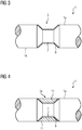
- FIG 2 shows an exemplary shaft 1.
- the shaft 1 comprises a base body 1a, the base body 1a having a recess 5.
- the shaft 1 here corresponds to the main body 1a and both are rotationally symmetrical.
- the recess 5 is preferably made in the base body 1a with the aid of a lathe, that is to say by machining.
- the recess 5 is trapezoidal here.
- the recess 5 can also have a rectangular cross section or a semicircular cross section.
- the recess 5 has a surface 7.
- the surface 7 and the recess 5 are arranged in the scanning area of the shaft 1.
- the recess 5 is arranged in the scanning area 3.
- FIG 3 shows a shaft 1 with a buffer layer 9.
- the buffer layer 9 is applied to the surface 7 in the recess 5.
- the buffer layer 9 is preferably applied to the surface 7 using a welding process.
- the buffer layer 9 is preferably applied to the surface 7 in the recess 5 of the base body 1a after it has been heated at least in the scanning area 3.
- the buffer layer 9 advantageously comprises at least two layers (not shown in the FIG).
- the first layer covers the surface 7 of the recess 5.
- the second layer advantageously covers the first layer.
- the buffer layer 9 is preferably applied in such a way that the surface 7 is completely covered by the buffer layer 9.
- FIG 4 shows a shaft 1 with a measuring layer 11.
- the measuring layer 11 is preferably applied to the buffer layer 9 with the aid of a welding process.
- the buffer layer 9 serves for the firm connection between the surface 5 of the base body 1a and the measuring layer 11.
- the measuring layer 11 is preferably made of a non-ferromagnetic material, preferably of an austenitic material.
- An example of a suitable material for the measuring layer 11 is an austenitic chromium-nickel steel with a low carbon content.
- FIG 5 shows a shaft 1 with a protruding measuring layer 11.
- the measuring layer 11 is applied with a buffer layer 7 on the base body 1a.
- the buffer layer and the measuring layer 11 are applied to the outer surface of a cylinder-shaped base body 1a.
- the buffer layer 9 serves to firmly connect the surface 7 of the body 1 to the measuring layer 11.
- the outer surface of the measuring layer 11 forms the scanning area 3.
- the outer surface of the measuring layer 11 in the shaft 1 has a larger radius than the shaft 1 itself.
- FIG 6 shows a shaft 1 with recess 5 and measuring layer 11.
- the measuring layer 11 is above the buffer layer 9 with the surface the recess 5 connected.
- the recess 5 has a rectangular cross section. The cross section is introduced rotationally symmetrically in the scanning area 3 of the base body 1a of the shaft 1.
- the radius of a lateral surface of the measuring layer 11 is smaller than the radius of the lateral surface of the further base body 1a of the shaft 1.
- FIG 7 shows an electrical machine 13 with a magnetic bearing 14.
- the magnetic bearing 14 is used for the rotatable mounting of the shaft 1.
- the magnetic bearing comprises a sensor 12, the sensor 12 being provided for determining the position and / or the orientation of the shaft 1.
- the magnetic bearing 14 is positioned in the encircled area of the housing of the electrical machine 13.
- the shaft 1 is part of a rotor 13a of the electrical machine 13.
- the sensor 12 is positioned such that the sensor 12 detects the scanning area 3 of the shaft 1.
- the invention relates to a shaft 1 with a scanning area 3.
- the shaft 1 is advantageously part of an electrical machine 13 with a magnetic bearing 14.
- the scanning area 3 of the shaft 1 is designed as a lateral surface of a measuring layer 11.
- the measuring layer 11 is connected to the surface 7 of a base body 1a of the shaft 1 via a buffer layer 9.
- the buffer layer 9 and the measuring layer 11 are preferably applied to the surface 7 of the base body 1a or to the buffer layer 9 with the aid of a welding process.
- the measuring layer 11 is preferably formed from an austenitic material.
- the buffer layer 9 and the measuring layer 11 are preferably positioned in a cutout 5 of the main body 1a of the shaft, so that the shaft 1 has an outer surface with a constant radius and a flush surface.
Landscapes
- Physics & Mathematics (AREA)
- General Physics & Mathematics (AREA)
- Measurement Of Length, Angles, Or The Like Using Electric Or Magnetic Means (AREA)
- Shafts, Cranks, Connecting Bars, And Related Bearings (AREA)
- Transmission And Conversion Of Sensor Element Output (AREA)
Priority Applications (2)
| Application Number | Priority Date | Filing Date | Title |
|---|---|---|---|
| EP18194806.8A EP3623767A1 (fr) | 2018-09-17 | 2018-09-17 | Arbre et procédé de fabrication d'un arbre, rotor et machine électrique |
| PCT/EP2019/074167 WO2020058047A1 (fr) | 2018-09-17 | 2019-09-11 | Arbre et procédé de fabrication d'un arbre, rotor et machine électrique |
Applications Claiming Priority (1)
| Application Number | Priority Date | Filing Date | Title |
|---|---|---|---|
| EP18194806.8A EP3623767A1 (fr) | 2018-09-17 | 2018-09-17 | Arbre et procédé de fabrication d'un arbre, rotor et machine électrique |
Publications (1)
| Publication Number | Publication Date |
|---|---|
| EP3623767A1 true EP3623767A1 (fr) | 2020-03-18 |
Family
ID=63637730
Family Applications (1)
| Application Number | Title | Priority Date | Filing Date |
|---|---|---|---|
| EP18194806.8A Withdrawn EP3623767A1 (fr) | 2018-09-17 | 2018-09-17 | Arbre et procédé de fabrication d'un arbre, rotor et machine électrique |
Country Status (2)
| Country | Link |
|---|---|
| EP (1) | EP3623767A1 (fr) |
| WO (1) | WO2020058047A1 (fr) |
Citations (7)
| Publication number | Priority date | Publication date | Assignee | Title |
|---|---|---|---|---|
| EP0212662A2 (fr) * | 1985-08-27 | 1987-03-04 | Kabushiki Kaisha S.G. | Dispositif de détection de position rotationnelle absolue |
| DE4431649A1 (de) * | 1994-09-06 | 1995-08-17 | Bosch Gmbh Robert | Sensoranordnung zur Bestimmung der Drehzahl eines sich bewegenden Bauteils |
| EP0866304A1 (fr) * | 1997-03-18 | 1998-09-23 | CARL ZEISS JENA GmbH | Système de mesure de longueurs |
| EP0984247A2 (fr) * | 1998-09-05 | 2000-03-08 | Oechsler Aktiengesellschaft | Capteur inductif |
| EP1052480A1 (fr) * | 1999-05-14 | 2000-11-15 | Rexroth Star GmbH | Dispositif de détection de la position relative de deux corps |
| WO2009059656A2 (fr) * | 2007-11-09 | 2009-05-14 | Vogt Electronic Components Gmbh | Capteur de position à corps en matière plastique |
| EP3203191A1 (fr) | 2016-02-03 | 2017-08-09 | Siemens Aktiengesellschaft | Capteur de palier magnetique |
-
2018
- 2018-09-17 EP EP18194806.8A patent/EP3623767A1/fr not_active Withdrawn
-
2019
- 2019-09-11 WO PCT/EP2019/074167 patent/WO2020058047A1/fr not_active Ceased
Patent Citations (7)
| Publication number | Priority date | Publication date | Assignee | Title |
|---|---|---|---|---|
| EP0212662A2 (fr) * | 1985-08-27 | 1987-03-04 | Kabushiki Kaisha S.G. | Dispositif de détection de position rotationnelle absolue |
| DE4431649A1 (de) * | 1994-09-06 | 1995-08-17 | Bosch Gmbh Robert | Sensoranordnung zur Bestimmung der Drehzahl eines sich bewegenden Bauteils |
| EP0866304A1 (fr) * | 1997-03-18 | 1998-09-23 | CARL ZEISS JENA GmbH | Système de mesure de longueurs |
| EP0984247A2 (fr) * | 1998-09-05 | 2000-03-08 | Oechsler Aktiengesellschaft | Capteur inductif |
| EP1052480A1 (fr) * | 1999-05-14 | 2000-11-15 | Rexroth Star GmbH | Dispositif de détection de la position relative de deux corps |
| WO2009059656A2 (fr) * | 2007-11-09 | 2009-05-14 | Vogt Electronic Components Gmbh | Capteur de position à corps en matière plastique |
| EP3203191A1 (fr) | 2016-02-03 | 2017-08-09 | Siemens Aktiengesellschaft | Capteur de palier magnetique |
Also Published As
| Publication number | Publication date |
|---|---|
| WO2020058047A1 (fr) | 2020-03-26 |
Similar Documents
| Publication | Publication Date | Title |
|---|---|---|
| DE3704049C2 (fr) | ||
| EP2753838B1 (fr) | Procédé de fabrication d'un palier de roulement | |
| DE102007017705A1 (de) | Wellenanordnung mit einem Wälzlager | |
| DE3423873A1 (de) | Rheometer | |
| DE102017105148A1 (de) | Drehwinkeldetektionseinrichtung und Drehmaschineneinrichtung | |
| DE4011766A1 (de) | Spannungsmessfuehler | |
| DE102016205495B4 (de) | Messvorrichtung und Verfahren zur Schichtdickenbestimmung sowie zugehöriger Referenzkörper und Kalibrierkörper | |
| EP3371553B1 (fr) | Capteur de palier magnetique | |
| DE3240480A1 (de) | Vorrichtung und verfahren zur zerstoerungsfreien materialpruefung mittels magnetischer streuflussmessung unter anwendung einer diagonal-quer-magnetisierung | |
| EP4031839A1 (fr) | Dispositif de mesure | |
| DE102014203517A1 (de) | Wälzlager mit einer integrierten Winkelmesseinrichtung | |
| DE10027095B4 (de) | Drehmomentdetektoranordnung | |
| DE2556340A1 (de) | Endstueck fuer messtaster | |
| EP3623767A1 (fr) | Arbre et procédé de fabrication d'un arbre, rotor et machine électrique | |
| WO2004031712A1 (fr) | Capteur de force servant a mesurer des forces d'arbre | |
| DE102015203119A1 (de) | Verfahren zum Detektieren von Fehlstellen in einem Kolben für eine Brennkraftmaschine | |
| DE102016122515A1 (de) | Prüf- und/oder Kalibriernormal | |
| WO2009124657A1 (fr) | Palier magnétique et procédé de fabrication d'une bague de palier adaptée | |
| DE4013429C2 (de) | Spannungsdetektor | |
| DE19702519A1 (de) | Magnetostriktionstyp- Drehmomenterfassungsvorrichtung | |
| EP0618445B1 (fr) | Procédé de contrôle non-déstructif des surfaces des matériaux électro-conducteurs | |
| DE3401140C1 (de) | Vorrichtung zur kontinuierlichen Messung der Dicke | |
| DE202016101583U1 (de) | Prüf- und/oder Kalibriernormal | |
| DE2445111B2 (fr) | ||
| EP4548087A1 (fr) | Procédé et dispositif de test de flux parasite de matériau de test ferromagnétique avec normalisation de signal |
Legal Events
| Date | Code | Title | Description |
|---|---|---|---|
| PUAI | Public reference made under article 153(3) epc to a published international application that has entered the european phase |
Free format text: ORIGINAL CODE: 0009012 |
|
| AK | Designated contracting states |
Kind code of ref document: A1 Designated state(s): AL AT BE BG CH CY CZ DE DK EE ES FI FR GB GR HR HU IE IS IT LI LT LU LV MC MK MT NL NO PL PT RO RS SE SI SK SM TR |
|
| AX | Request for extension of the european patent |
Extension state: BA ME |
|
| STAA | Information on the status of an ep patent application or granted ep patent |
Free format text: STATUS: THE APPLICATION IS DEEMED TO BE WITHDRAWN |
|
| 18D | Application deemed to be withdrawn |
Effective date: 20200919 |