EP3623825A1 - Dispositif électronique de commande - Google Patents
Dispositif électronique de commande Download PDFInfo
- Publication number
- EP3623825A1 EP3623825A1 EP17908774.7A EP17908774A EP3623825A1 EP 3623825 A1 EP3623825 A1 EP 3623825A1 EP 17908774 A EP17908774 A EP 17908774A EP 3623825 A1 EP3623825 A1 EP 3623825A1
- Authority
- EP
- European Patent Office
- Prior art keywords
- grounding
- current
- electronic control
- control device
- ground
- Prior art date
- Legal status (The legal status is an assumption and is not a legal conclusion. Google has not performed a legal analysis and makes no representation as to the accuracy of the status listed.)
- Granted
Links
Images





Classifications
-
- G—PHYSICS
- G01—MEASURING; TESTING
- G01R—MEASURING ELECTRIC VARIABLES; MEASURING MAGNETIC VARIABLES
- G01R31/00—Arrangements for testing electric properties; Arrangements for locating electric faults; Arrangements for electrical testing characterised by what is being tested not provided for elsewhere
- G01R31/50—Testing of electric apparatus, lines, cables or components for short-circuits, continuity, leakage current or incorrect line connections
- G01R31/54—Testing for continuity
-
- B—PERFORMING OPERATIONS; TRANSPORTING
- B60—VEHICLES IN GENERAL
- B60L—PROPULSION OF ELECTRICALLY-PROPELLED VEHICLES; SUPPLYING ELECTRIC POWER FOR AUXILIARY EQUIPMENT OF ELECTRICALLY-PROPELLED VEHICLES; ELECTRODYNAMIC BRAKE SYSTEMS FOR VEHICLES IN GENERAL; MAGNETIC SUSPENSION OR LEVITATION FOR VEHICLES; MONITORING OPERATING VARIABLES OF ELECTRICALLY-PROPELLED VEHICLES; ELECTRIC SAFETY DEVICES FOR ELECTRICALLY-PROPELLED VEHICLES
- B60L3/00—Electric devices on electrically-propelled vehicles for safety purposes; Monitoring operating variables, e.g. speed, deceleration or energy consumption
- B60L3/0023—Detecting, eliminating, remedying or compensating for drive train abnormalities, e.g. failures within the drive train
- B60L3/0046—Detecting, eliminating, remedying or compensating for drive train abnormalities, e.g. failures within the drive train relating to electric energy storage systems, e.g. batteries or capacitors
-
- G—PHYSICS
- G01—MEASURING; TESTING
- G01R—MEASURING ELECTRIC VARIABLES; MEASURING MAGNETIC VARIABLES
- G01R1/00—Details of instruments or arrangements of the types included in groups G01R5/00 - G01R13/00 and G01R31/00
- G01R1/20—Modifications of basic electric elements for use in electric measuring instruments; Structural combinations of such elements with such instruments
- G01R1/203—Resistors used for electric measuring, e.g. decade resistors standards, resistors for comparators, series resistors, shunts
-
- G—PHYSICS
- G01—MEASURING; TESTING
- G01R—MEASURING ELECTRIC VARIABLES; MEASURING MAGNETIC VARIABLES
- G01R31/00—Arrangements for testing electric properties; Arrangements for locating electric faults; Arrangements for electrical testing characterised by what is being tested not provided for elsewhere
- G01R31/36—Arrangements for testing, measuring or monitoring the electrical condition of accumulators or electric batteries, e.g. capacity or state of charge [SoC]
- G01R31/364—Battery terminal connectors with integrated measuring arrangements
-
- G—PHYSICS
- G01—MEASURING; TESTING
- G01R—MEASURING ELECTRIC VARIABLES; MEASURING MAGNETIC VARIABLES
- G01R31/00—Arrangements for testing electric properties; Arrangements for locating electric faults; Arrangements for electrical testing characterised by what is being tested not provided for elsewhere
- G01R31/005—Testing of electric installations on transport means
- G01R31/006—Testing of electric installations on transport means on road vehicles, e.g. automobiles or trucks
Definitions
- the present invention relates to an electronic control device including a configuration capable of detecting a ground open condition.
- each drive control system includes the control circuit including a microcomputer.
- the control circuits are connected to each other by a communication line, and have grounds isolated from each other.
- Patent Literature 2 includes a power supply system ground and a signal system ground, and is configured so that those grounds are isolated from each other.
- a ground open condition is detected for each ground by an openness detector formed of a comparator.
- one input of the comparator is connected to the ground, and a voltage to be used as a reference is input to the other input.
- a break occurs in a ground line
- the ground becomes open
- the voltage of ground input is pulled up to an internal power supply voltage by a pull-up resistor. This causes a change in output signal voltage level of the comparator, which allows a ground open condition to be detected as a failure.
- the present invention has been made in order to solve such problems as described above, and has an object to obtain an electronic control device capable of detecting a ground open condition even when employing a configuration that achieves the commonality of a plurality of grounds in the device by connecting the grounds to each other.
- an electronic control device including: a plurality of grounding terminals provided to a plurality of grounds in the device individually on a one-to-one basis; a grounding common portion for connecting a plurality of grounding points provided to the plurality of grounds individually on a one-to-one basis; a current detection unit configured to detect each of currents flowing between the plurality of grounding points and the plurality of grounding terminals provided for the plurality of grounding points individually on a one-to-one basis or a current flowing through the grounding common portion; and a controller configured to detect a ground open condition for each of the plurality of grounds by comparing a detection result obtained by the current detection unit with a determination value for determining the ground open condition.
- an electronic control device capable of detecting a ground open condition even when employing a configuration that achieves the commonality of a plurality of grounds in the device by connecting the grounds to each other can be obtained.
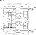
- FIG. 1 is a circuit diagram of an electronic control device 1 according to a first embodiment of the present invention.
- Connector terminals for power supply of the electronic control device 1 illustrated in FIG. 1 are electrically connected to batteries 3a and 3b being power sources mounted to a vehicle.
- a power supply terminal Ta+ is connected to a positive terminal of the battery 3a
- a grounding terminal Ta- is connected to a negative terminal of the battery 3a.
- a power supply terminal Tb+ is connected to a positive terminal of the battery 3b
- a grounding terminal Tb- is connected to a negative terminal of the battery 3b.
- the electronic control device 1 includes: the plurality of grounding terminals Ta- and Tb- provided to the plurality of grounds Ga and Gb in the device individually on a one-to-one basis; and a grounding common portion C for connection between a plurality of grounding points Pa and Pb provided to the plurality of grounds Ga and Gb individually on a one-to-one basis.
- the grounding common portion C achieves the commonality of the grounds Ga and Gb.
- the plurality of grounding terminals Ta- and Tb- are individually connected to the negative terminals of the plurality of batteries 3a and 3b, and the commonality of the grounds is achieved at some midpoint of each path involving the connection.
- the electronic control device 1 includes a circuit group 1a and a circuit group 1b having the same circuit configuration.
- the circuit groups 1a and 1b are supplied with electric power from the batteries 3a and 3b, respectively.
- the circuit groups 1a and 1b are electrically connected to actuators 2a and 2b serving as target devices to be controlled, respectively.
- a group of the circuit group 1a, the actuator 2a, and the battery 3a is set as a "first system”
- a group of the circuit group 1b, the actuator 2b, and the battery 3b is set as a "second system”.
- the first system operates with the electric power supplied from the battery 3a
- the second system operates with the electric power supplied from the battery 3b.
- Each embodiment is described by taking as an example the electronic control device 1 having two systems of the first system and the second system, but the electronic control device 1 may have three or more systems.
- "a” is appended to a reference symbol of each of components forming the first system
- "b” is appended to a reference symbol of each of components forming the second system.
- the circuit group 1a includes a drive unit 11a, a microcomputer 12a, a differential amplifier 13a, and a resistor 14a.
- the circuit group 1b includes a drive unit 11b, a microcomputer 12b, a differential amplifier 13b, and a resistor 14b.
- the drive units 11a and 11b are electrically connected to the actuators 2a and 2b, respectively.
- the microcomputers 12a and 12b output control signals to the drive units 11a and 11b electrically connected thereto, respectively.
- the microcomputers 12a and 12b output the control signals to the drive units 11a and 11b, to thereby operate the actuators 2a and 2b through the intermediation of the drive units 11a and 11b.
- large currents flow to the drive units 11a and 11b.
- the plurality of circuit groups 1a and 1b are provided for the plurality of grounding terminals Ta- and Tb- individually on a one-to-one basis.
- the circuit groups 1a and 1b also include the drive units 11a and 11b, which are connected to the microcomputers 12a and 12b and the grounds Ga and Gb, and is configured to drive the actuators 2a and 2b serving as the target devices under control of the microcomputers 12a and 12b, respectively.
- the grounds Ga and Gb are grounds of the circuit groups 1a and 1b electrically connected to the grounding terminals Ta- and Tb-.
- the resistors 14a and 14b serving as current detectors for detecting currents flowing through the grounds Ga and Gb are provided in the vicinities of the grounding terminals Ta- and Tb-, respectively.
- the differential amplifiers 13a and 13b output voltages obtained by amplifying potential differences between both ends of the resistors 14a and 14b.
- the output voltages output from the differential amplifiers 13a and 13b are input to the microcomputers 12a and 12b, respectively.
- the microcomputers 12a and 12b can acquire ground currents Ia and Ib flowing through the grounding terminals Ta- and Tb- by, for example, measuring the output voltages from the differential amplifiers 13a and 13b by built-in A/D converters.
- ground Ga and the ground Gb are connected to each other by the grounding common portion C.
- the grounding point Pa between the ground Ga and the grounding common portion C is located on the drive unit 11a side of nodes connecting the differential amplifier 13a and the resistor 14a.
- the grounding point Pb between the ground Gb and the grounding common portion C is located on the drive unit 11b side of nodes connecting the differential amplifier 13b and the resistor 14b.
- the plurality of current detectors (namely, plurality of resistors 14a and 14b) provided for the plurality of grounds Ga and Gb individually on a one-to-one basis function as current detection units configured to detect the currents (namely, ground currents Ia and Ib) flowing between the plurality of grounding points Pa and Pb and the plurality of grounding terminals Ta- and Tb- provided for the plurality of grounding points Pa and Pb individually on a one-to-one basis.
- the plurality of resistors 14a and 14b detect the ground currents Ia and Ib flowing between the corresponding grounding points Pa and Pb and the corresponding grounding terminals Ta- and Tb-, respectively.
- the microcomputers 12a and 12b of the plurality of circuit groups 1a and 1b each function as a controller configured to detect a ground open condition for each of the grounds Ga and Gb by comparing a detection result obtained by the current detection unit with a determination value for determining a ground open condition.
- the microcomputers 12a and 12b are connected to each other by a communication line L.
- the microcomputer 12a and the microcomputer 12b exchange data between the microcomputers 12a and 12b inside the electronic control device 1 in order to mutually monitor a failure and perform a coordinated operation.
- the data may possibly fail to be exchanged appropriately to exert influences on, for example, the determination and operations performed by the microcomputers 12a and 12b. Therefore, in such a configuration, the circuit groups 1a and 1b are expected to have a single ground level.
- FIG. 2 is a perspective view of a bus bar 4 in the first embodiment of the present invention.
- FIG. 3 is a bottom view of FIG. 2.
- FIG. 2 and FIG. 3 are diagrams with a focus on the resistors 14a and 14b each having a U-shape.
- the resistors 14a and 14b are formed as parts of the bus bar 4, and each have a U-shape.
- the shape of each of the resistors 14a and 14b is possible to reduce an inductance component in the resistor, and as a result, improve accuracy in detection of a current.
- a pair of bus bar terminal portions 43a are caused to extend from both the ends of the resistor 14a in close proximity to each other.
- the bus bar terminal portions 43a By causing the bus bar terminal portions 43a to extend from both the ends of the resistor 14a in close proximity to each other, it is possible to reduce electromagnetic field noise and other such influences from the outside, and as a result, improve the accuracy in detection of a current.
- the resistors 14a and 14b are formed as parts of the bus bar 4, for example, a resistor component for the current detector and an assembly process for the resistor component are no longer required, and as a result, the effects of manufacturing cost reduction and downsizing of the electronic control device 1 are produced.
- grounding common portion C is also formed to the bus bar 4, and a pair of bus bar terminal portions 42 are caused to extend from the grounding common portion C.
- the bus bar terminal portions 42, 43a, and 43b are electrically connected to a circuit board 5 on which electronic components forming the circuits of the microcomputers 12a and 12b and the differential amplifiers 13a and 13b, which are illustrated in FIG. 1 , are packaged.
- the bus bar terminal portions 43a and 43b are electrically connected to the differential amplifiers 13a and 13b (not shown) .
- bus bar terminal portions 41a and 41b which are caused to extend from one of the resistors 14a and 14b to form parts of the bus bar 4, are electrically connected to the grounding terminals Ta- and Tb- (not shown).
- power supply lines (not shown) connecting the drive units 11a and 11b to the power supply terminals Ta+ and Tb+ and the grounding terminals Ta- and Tb-, which are illustrated in FIG. 1 , are formed separately from the circuit board 5, and ground lines of the power supply lines are connected to the bus bar 4.
- impedances between the grounding terminals Ta- and Tb- and the grounding points Pa and Pb are matched. Between the grounding terminals Ta- and Tb- and the grounding points Pa and Pb, the impedances can be matched by, for example, using the same material, length, width, and thickness of circuit wiring or using the same components.
- the impedances between the plurality of grounding points Pa and Pb and the plurality of grounding terminals Ta- and Tb- provided for the plurality of grounding points Pa and Pb individually on a one-to-one basis, respectively, are matched with each other.
- the bus bar 4 is formed between the grounding terminals Ta- and Tb- and the grounding points Pa and Pb as illustrated in FIG. 2 and FIG. 3 , and therefore the impedances are matched by, for example, using the same material, length, width, thickness, and shape of the bus bar 4.
- the ground current Ia passes through the resistor 14a and the grounding terminal Ta- to flow to the negative terminal of the battery 3a.
- the circuit group 1b the current Ia flows through the resistor 14a, and the current Ib flows through the resistor 14b.
- FIG. 4 is a circuit diagram for illustrating a condition in which the grounding terminal Tb- becomes open in the electronic control device 1 illustrated in FIG. 1 .
- a case in which the grounding terminal Tb- becomes open is considered as a specific example in which a ground open condition has occurred.
- the circuit group 1b when a break occurs in a wire between the grounding terminal Tb- of the circuit group 1b and the negative terminal of the battery 3b, the circuit group 1b is brought to a ground open condition. In this case, the ground current Ib is inhibited from flowing to the negative terminal of the battery 3b through the grounding terminal Tb-.
- the negative terminals of the batteries 3a and 3b are often grounded to the body of the vehicle.
- the ground current Ib passes from the grounding common portion C through the resistor 14a and the grounding terminal Ta-, and then passes from the negative terminal of the battery 3a grounded to the body through the negative terminal of the battery 3b grounded to the body, to thereby flow to the battery 3b.
- the circuit group 1b continues the operation even after a ground open condition has occurred, which leads to a potential failure condition.
- a current flowing through the resistor 14b of the circuit group 1b in which the ground open condition has occurred is zero.
- a current flowing through the resistor 14a of the circuit group 1a in which no ground open condition has occurred is Ia+Ib.
- the electronic control device 1 is configured to detect the currents by the resistors 14a and 14b, to thereby be able to detect a ground open condition for each of the grounds Ga and Gb.
- the microcomputers 12a and 12b of the electronic control device 1 are configured to determine a ground open condition by, for example, the following method.
- the microcomputer 12a acquires a current value detected by the resistor 14a, and when the acquired current value is equal to or smaller than a determination value THa, determines that a ground open condition has occurred in the circuit group 1a, namely, the ground Ga.
- the microcomputer 12b acquires a current value detected by the resistor 14b, and when the acquired current value is equal to or smaller than a determination value THb, determines that a ground open condition has occurred in the circuit group 1b, namely, the ground Gb.
- a ground current flowing through the resistor of a circuit group in which a ground open condition has occurred is zero, but a difference between the ground current and each of the ground currents Ia and Ib flowing when the actuators 2a and 2b are not in operation is too small to be detected by the resistors 14a and 14b.
- the determination values THa and THb to be used for determining a ground open condition are described. Under normal conditions, that is, when the grounds are not open, the ground currents Ia and Ib flow through the resistors 14a and 14b, respectively.
- the determination value THa is a value set in advance, and is set so as to be smaller than, for example, the ground current Ia flowing when the actuator 2a is in operation.
- the determination value THb is a value set in advance, and is set so as to be smaller than, for example, the ground current Ib flowing when the actuator 2b is in operation.
- the microcomputer 12a can detect a ground open condition by the following method in the same manner as described above.
- the circuit group 1a includes the resistor 14a, and hence when, for example, the grounding terminal Ta- becomes open, the microcomputer 12a can detect a ground open condition in the above-mentioned manner. That is, the microcomputer 12a acquires the current value detected by the resistor 14a, and when the acquired current value is equal to or smaller than a determination value TH1, determines that a ground open condition has occurred in the circuit group 1a.
- the microcomputer 12a acquires the current value detected by the resistor 14a, and when the acquired current value is equal to or larger than a determination value TH2, determines that a ground open condition has occurred in the circuit group 1b.
- the determination value TH1 is a value set in advance, and is set so as to be smaller than, for example, the ground current Ia flowing when the actuator 2a is in operation.
- the determination value TH2 is a value set in advance to be larger than the determination value TH1, and is set so as to be smaller than, for example, a sum of the ground current Ia flowing when the actuator 2a is in operation and the ground current Ib flowing when the actuator 2b is in operation.
- the microcomputer 12a determines that a ground open condition has occurred in the circuit group 1a.
- the microcomputer 12a determines that the circuit group 1a and the circuit group 1b are under normal conditions.
- the microcomputer 12a determines that a ground open condition has occurred in the circuit group 1b.
- one current detector (namely, resistor 14a) provided for any one of the plurality of grounds Ga and Gb on a one-to-one basis functions as a current detection unit configured to detect any one (namely, ground current Ia) of the currents (namely, ground currents Ia and Ib) flowing between the plurality of grounding points Pa and Pb and the plurality of grounding terminals Ta- and Tb- provided for the plurality of grounding points Pa and Pb individually on a one-to-one basis.
- the electronic control device is configured to cause the current detection units to detect the currents flowing between a plurality of grounding points connected to each other by a grounding common portion and a plurality of grounding terminals provided for the plurality of grounding points individually on a one-to-one basis, and compare the detection results obtained by the current detection units with the determination values for determining a ground open condition, to thereby detect a ground open condition for each ground.
- the electronic control device can cause, for example, a microcomputer of a circuit group in which a ground open condition has been detected to notify a microcomputer of the other circuit group of a failure condition.
- the electronic control device can cause the microcomputer of the circuit group in which a ground open condition has been detected to notify the external device of a failure condition.
- the electronic control device can suppress the current flowing to the grounding terminal that is not open by, for example, stopping driving the actuator connected to the circuit group in which a ground open condition has been detected.
- the electronic control device is configured to be able to detect a ground open condition that can occur in each circuit group, and therefore contributes to the achievement of the electronic control device having high reliability.
- the first embodiment has been described by taking an exemplary case in which the resistors 14a and 14b are configured as parts of the bus bar 4, but the present invention is not limited thereto, and the resistors 14a and 14b may be, for example, shunt resistors.
- the negative terminal of the battery is grounded by the body of the vehicle
- the grounding terminals of the electronic control device mounted to the vehicle are often grounded to the body of the vehicle as well.
- the grounding terminals Ta- and Tb- of the electronic control device 1 may be grounded to the body together with the ground terminals of another electronic control device.
- the grounding terminals Ta- and Tb- are open to the batteries, but are connected to the grounding terminals of the other electronic control device.
- a ground current of the other electronic control device flows from the grounding terminal Tb- in the same manner as in FIG. 4 , and passes through the grounding common portion C and the grounding terminal Ta- to flow to the battery 3b from the negative terminal of the battery 3a grounded to the body through the negative terminal of the battery 3b grounded to the body.
- a current that is, negative current value
- a current flowing in a direction reverse to that of a current flowing under normal conditions that is, when the ground is not open
- the resistor 14b detects such a ground open condition that a current flows from another electronic control device to the electronic control device 1 as well.
- the grounding common portion C is provided with a relay, a fuse, or other such cut-off circuit, to thereby be able to cut off the current flowing into the grounding terminal Ta- as well.
- the first embodiment presupposes that a plurality of batteries are provided with the negative terminals of the batteries being grounded to the body of the vehicle, but it is to be understood that the same effects can be produced when, for example, one battery is provided with the negative terminal of the battery being connected to a plurality of grounding terminals.
- a determination method for a ground open condition a method of determining a ground open condition by comparing the current values detected by the resistors 14a and 14b during the operations of the actuators 2a and 2b with a determination value set in advance is employed.
- the microcomputers 12a and 12b learn the current values detected by the resistors 14a and 14b when the actuators 2a and 2b are not in operation, and values obtained by adding a value set in advance to the learned current values are set as the determination values THa and THb.
- the determination values THa and THb can easily be obtained irrespective of the variations of the detected current values.
- the microcomputers 12a and 12b learn the current values detected by the resistors 14a and 14b when the actuators 2a and 2b are not in operation, and change the determination values THa and THb based on the learned current values .
- the microcomputers 12a and 12b may be configured to learn the current values detected by the resistors 14a and 14b when the actuators 2a and 2b are in operation but the currents flowing through the resistors 14a and 14b are sufficiently small.
- the second embodiment there is provided a configuration of learning the currents detected by the current detection units when the target devices are not in operation or when the target devices are in operation but the currents flowing through the current detection units are sufficiently small, and changing the determination values based on the learned current values.
- this configuration it is possible to set the determination values in consideration of the variations of the detected current values, and to achieve improvement of accuracy in determination.
- a description is given of the electronic control device 1 including current detectors each having a configuration different from that of the first embodiment.
- a description is omitted for the same points as those of the first embodiment, and is mainly given of points different from the first embodiment.
- FIG. 5 is a circuit diagram of the electronic control device 1 according to the third embodiment of the present invention.
- the current detectors for detecting the currents flowing in the grounds Ga and Gb are formed of the resistors 14a and 14b provided to the grounds Ga and Gb, respectively, as illustrated in FIG. 1 .
- the current detectors in the third embodiment each have a configuration different from that of the first embodiment.
- the circuit groups 1a and 1b include, as the current detectors, Hall current sensors 15a and 15b each configured to detect a current value from a magnetic field generated by the current.
- the Hall current sensors 15a and 15b serving as the current detectors for detecting the currents flowing through the grounds Ga and Gb are provided in the vicinities of the grounds Ga and Gb and in the vicinities of the grounding terminals Ta- and Tb-, respectively.
- Output from the Hall current sensors 15a and 15b is input to the microcomputers 12a and 12b.
- the microcomputers 12a and 12b can acquire ground currents Ia and Ib flowing through the grounding terminals Ta- and Tb- by, for example, measuring the output voltages from the Hall current sensors 15a and 15b by built-in A/D converters.
- a current detected by the Hall current sensor 15a is Ia
- a current detected by the Hall current sensor 15b is Ib.
- FIG. 6 is a circuit diagram for illustrating a condition in which the grounding terminal Tb- becomes open in the electronic control device 1 illustrated in FIG. 5 .
- a case in which the grounding terminal Tb- becomes open is considered as a specific example in which a ground open condition has occurred.
- the electronic control device 1 can also be configured to learn the current values detected by the Hall current sensors 15a and 15b when the actuators 2a and 2b are not in operation, and set values obtained by adding a value set in advance to the learned current values as the determination values THa and THb.
- a Hall current sensor is used as the current detector in place of the resistor. Even with this configuration, the same effects as those of the first and second embodiments can be produced.
- the Hall current sensor is provided as an example of the current detector configured to detect a current from the magnetic field generated by the current, but the present invention is not limited thereto. That is, as such a current detector, instead of the Hall current sensor, for example, a giant magneto resistance (GMR), a tunnel magneto resistance (TMR), or other such magneto-resistive current sensor may be used, or another current sensor of a magnetic field detection method may be used.
- GMR giant magneto resistance
- TMR tunnel magneto resistance
- a description is omitted for the same points as those of the first embodiment, and is mainly given of points different from the first embodiment.
- FIG. 7 is a circuit diagram of the electronic control device 1 according to the fourth embodiment of the present invention.
- the current detectors for detecting the currents flowing in the grounds Ga and Gb are formed of the resistors 14a and 14b provided to the grounds Ga and Gb, respectively, as illustrated in FIG. 1 .
- the current detectors in the fourth embodiment each have a configuration different from that of the first embodiment. That is, one current detector provided to the grounding common portion C, which is configured to detect the current flowing through the grounding common portion C, functions as a current detection unit configured to detect the current flowing through the grounding common portion C.
- the current detector in the fourth embodiment is formed of a resistor 16 provided to the grounding common portion C.
- the differential amplifiers 13a and 13b are each configured to output a voltage obtained by amplifying a potential difference between both ends of the resistor 16.
- the built-in A/D converters of the microcomputers 12a and 12b have an input voltage range from 0 V to 5 V and measure the output voltages from the differential amplifiers 13a and 13b by the built-in A/D converters.
- the differential amplifiers 13a and 13b each output 2.5 V being a median value of the input voltage range of the A/D converter.
- the differential amplifiers 13a and 13b each output a voltage larger than 2.5 V.
- the microcomputers 12a and 12b each measure the output value (>2.5 V), to thereby acquire the current value of the current flowing through the resistor 16 as a positive value.
- the differential amplifiers 13a and 13b each output a voltage smaller than 2.5 V.
- the microcomputers 12a and 12b each measure the output value ( ⁇ 2.5 V), to thereby acquire the current value of the current flowing through the resistor 16 as a negative value.
- the ground currents Ia and Ib of the circuit groups 1a and 1b flow to the negative terminals of the batteries 3a and 3b through the grounding terminals Ta- and Tb-, respectively.
- impedances between the grounding terminals Ta- and Tb- and the grounding points Pa and Pb are matched with each other, and an impedance between the grounding points Pa and Pb is matched therewith. Therefore, as normal conditions, the potential difference between the grounding points Pa and Pb, that is, the potential difference between both the ends of the resistor 16 is small, and the current flowing through the resistor 16 is also small.
- FIG. 8 is a circuit diagram for illustrating a condition in which the grounding terminal Tb- becomes open in the electronic control device 1 illustrated in FIG. 7 .
- a case in which the grounding terminal Tb- becomes open is considered as a specific example in which a ground open condition has occurred.
- ground currents Ia and Ib flow along the same paths as those of the first embodiment.
- the ground current Ib flows through the resistor 16 in a direction from the circuit group 1b side to the circuit group 1a side.
- a current value detected by the resistor 16 is -Ib (namely, negative value).
- the current value detected by the resistor 16 is Ia (namely, positive value). In this manner, the current value becomes positive or negative depending on the direction in which the current flows.
- the microcomputers 12a and 12b of the electronic control device 1 are configured to determine a ground open condition by, for example, the following method. Under normal conditions, that is, when the grounds are not open, the current value detected by the resistor 16 is zero.
- the microcomputers 12a and 12b acquire the current value detected by the resistor 16 during the operations of the actuators 2a and 2b, and when the acquired current value is equal to or larger than a determination value TH3, determine that a ground open condition has occurred in the circuit group 1a.
- the microcomputers 12a and 12b acquire the current value detected by the resistor 16 during the operations of the actuators 2a and 2b, and when the acquired current value is equal to or smaller than a determination value TH4, determine that a ground open condition has occurred in the circuit group 1b.
- the determination value TH3 is a positive value set in advance, and is set so as to be smaller than, for example, the ground current Ia flowing when the actuator 2a is in operation.
- the determination value TH4 is a negative value set in advance, and is set so that an absolute value of the determination value TH4 is smaller than, for example, the ground current Ib flowing when the actuator 2b is in operation.
- the resistor 16 may be formed as a part of the bus bar 4 as illustrated in FIG. 2 and FIG. 3 , or may be a shunt resistor.
- the resistor 16 may have a U-shape as illustrated in FIG. 2 and FIG. 3 .
- the Hall current sensor may be used as the current detector in place of the resistor 16.
- the electronic control device 1 may also learn the current value detected by the resistor 16 when the actuators 2a and 2b are not in operation, and set the determination value TH3 and the determination value TH4 based on the learned current value (learned value).
- the determination value TH3 is set to a value larger than the learned current value
- the determination value TH4 is set to a value smaller than the learned current value.
- the learned current value is not always zero, and hence the determination value TH3 and the determination value TH4 may be positive values, negative values, or zero without question, which satisfies the following relational expression.
- the microcomputers 12a and 12b learn the current value detected by the resistor 16 when the actuators 2a and 2b are not in operation, and change the determination values TH3 and TH4 based on the learned current value.
- the electronic control device is configured to cause the current detection unit to detect the current flowing through the grounding common portion for connecting a plurality of grounding points provided to a plurality of grounds in the device individually on a one-to-one basis, and compare the detection result obtained by the current detection unit with the determination values for determining a ground open condition, to thereby detect a ground open condition for each ground.
- 1 electronic control device 1a, 1b circuit group, 11a, 11b drive unit, 12a, 12b microcomputer, 13a, 13b differential amplifier, 14a, 14b resistor, 15a, 15b Hall current sensor, 16 resistor, 2a, 2b actuator, 3a, 3b battery, 4 bus bar, 41a, 41b bus bar terminal portion, 42 bus bar terminal portion, 43a, 43b bus bar terminal portion, 5 circuit board, Ta+, Tb+ power supply terminal, Ta-, Tb- grounding terminal, Ga, Gb ground, Pa, Pb grounding point, C grounding common portion, L communication line
Landscapes
- Engineering & Computer Science (AREA)
- Physics & Mathematics (AREA)
- General Physics & Mathematics (AREA)
- Power Engineering (AREA)
- Life Sciences & Earth Sciences (AREA)
- Sustainable Development (AREA)
- Sustainable Energy (AREA)
- Transportation (AREA)
- Mechanical Engineering (AREA)
- Testing Of Short-Circuits, Discontinuities, Leakage, Or Incorrect Line Connections (AREA)
Applications Claiming Priority (1)
| Application Number | Priority Date | Filing Date | Title |
|---|---|---|---|
| PCT/JP2017/017892 WO2018207319A1 (fr) | 2017-05-11 | 2017-05-11 | Dispositif électronique de commande |
Publications (3)
| Publication Number | Publication Date |
|---|---|
| EP3623825A1 true EP3623825A1 (fr) | 2020-03-18 |
| EP3623825A4 EP3623825A4 (fr) | 2020-05-27 |
| EP3623825B1 EP3623825B1 (fr) | 2023-03-22 |
Family
ID=64105298
Family Applications (1)
| Application Number | Title | Priority Date | Filing Date |
|---|---|---|---|
| EP17908774.7A Active EP3623825B1 (fr) | 2017-05-11 | 2017-05-11 | Dispositif électronique de commande |
Country Status (5)
| Country | Link |
|---|---|
| US (1) | US11131720B2 (fr) |
| EP (1) | EP3623825B1 (fr) |
| JP (1) | JP6789387B2 (fr) |
| CN (1) | CN110603451B (fr) |
| WO (1) | WO2018207319A1 (fr) |
Cited By (1)
| Publication number | Priority date | Publication date | Assignee | Title |
|---|---|---|---|---|
| WO2022253648A1 (fr) * | 2021-06-01 | 2022-12-08 | Robert Bosch Gmbh | Ensemble, véhicule automobile et procédé de surveillance d'un ensemble |
Families Citing this family (5)
| Publication number | Priority date | Publication date | Assignee | Title |
|---|---|---|---|---|
| JP7319857B2 (ja) * | 2019-08-06 | 2023-08-02 | 日立Astemo株式会社 | 電子制御装置及びその故障検知方法 |
| DE102019126953B3 (de) * | 2019-10-08 | 2020-10-08 | Eberspächer Controls Landau Gmbh & Co. Kg | Steuergerät für ein Fahrzeug |
| DE102021214955A1 (de) * | 2021-12-22 | 2023-06-22 | Continental Automotive Technologies GmbH | Verfahren zur Detektion eines Masseanbindungsverlust, Steuergerät und Bremssystem |
| CN119013862A (zh) * | 2022-01-17 | 2024-11-22 | 邦奇动力有限责任公司 | 安全电路、功率转换器和功率系统 |
| CN119561454A (zh) * | 2023-08-23 | 2025-03-04 | 深圳引望智能技术有限公司 | 电机控制电路及相关装置 |
Family Cites Families (36)
| Publication number | Priority date | Publication date | Assignee | Title |
|---|---|---|---|---|
| US3158806A (en) * | 1960-10-03 | 1964-11-24 | Consolidation Coal Co | Apparatus for performing a ground line continuity test at reduced voltage |
| US3729653A (en) * | 1971-11-08 | 1973-04-24 | Gen Electric | Ground conductor continuity checking circuit |
| US4649454A (en) * | 1984-10-09 | 1987-03-10 | Winterton Arvin O | Apparatus and method for detecting an open ground connection |
| JPH04134080U (ja) * | 1991-06-03 | 1992-12-14 | 多摩川精機株式会社 | グランドラインの断線検出装置 |
| JP3338587B2 (ja) * | 1995-07-19 | 2002-10-28 | 日本信号株式会社 | 漏電検出器 |
| JP3010422B2 (ja) * | 1995-09-20 | 2000-02-21 | 矢崎総業株式会社 | 電気接続箱のバスバー構造 |
| DE19723928A1 (de) * | 1997-06-06 | 1998-12-10 | Bosch Gmbh Robert | Vorrichtung zur Anbindung von Referenzmassen an integrierte Schaltungen |
| US6278596B1 (en) * | 1999-06-17 | 2001-08-21 | Tektronix, Inc. | Active ground fault disconnect |
| IT1320013B1 (it) * | 2000-04-04 | 2003-11-12 | Magneti Marelli Spa | Diagnosi del cablaggio di massa in moduli circuitali con connessionemultipla a massa, particolarmente per unita' elettroniche a bordo di |
| US6552885B1 (en) * | 2000-09-06 | 2003-04-22 | Ipc Resistors Inc. | Ground fault circuit having circuit failure sensor, and method |
| US6583975B2 (en) * | 2001-02-01 | 2003-06-24 | Hydro-Aire, Inc. | Aircraft applicable ground fault circuit interrupter |
| US7312964B2 (en) * | 2004-02-17 | 2007-12-25 | Tchernobrivets Serguei Borissovitch | Ground-fault monitor for multiple circuits |
| JP4680042B2 (ja) * | 2005-05-16 | 2011-05-11 | 本田技研工業株式会社 | 制御回路装置 |
| JP2008158916A (ja) | 2006-12-26 | 2008-07-10 | Rohm Co Ltd | 監視カメラ装置及びこれを用いた監視カメラシステム |
| DE102008037400A1 (de) * | 2007-10-30 | 2009-05-07 | Denso Corporation, Kariya | Lasttreiber mit Drahtbruch-Erfassungsschaltung |
| CN201156662Y (zh) * | 2008-01-27 | 2008-11-26 | 陈校波 | 单片机控制的接地检测保护电路 |
| JP5334500B2 (ja) * | 2008-08-29 | 2013-11-06 | 三洋電機株式会社 | 車両用の電源装置 |
| EP2416435B1 (fr) | 2009-03-31 | 2018-08-29 | Sanyo Electric Co., Ltd. | Module de batterie, système de batterie et véhicule électrique |
| JP2011164008A (ja) * | 2010-02-12 | 2011-08-25 | Denso Corp | 電流検出装置 |
| JP5617278B2 (ja) * | 2010-02-26 | 2014-11-05 | 株式会社デンソー | 電流検出装置 |
| US9662987B2 (en) * | 2011-02-18 | 2017-05-30 | Lear Corporation | Method and apparatus for detecting the existence of a safety ground |
| JP5730161B2 (ja) * | 2011-09-02 | 2015-06-03 | ルネサスエレクトロニクス株式会社 | 電圧監視回路及びそのテスト方法、電圧監視システム |
| JP5944507B2 (ja) * | 2012-12-27 | 2016-07-05 | 新電元工業株式会社 | 充電装置、および、アース確認方法 |
| US9851392B2 (en) * | 2013-01-10 | 2017-12-26 | Nxp Usa, Inc. | Ground-loss detection circuit |
| JP5595551B1 (ja) * | 2013-04-01 | 2014-09-24 | 三菱電機株式会社 | モータ制御装置、およびモータ制御装置を備えた電動パワーステアリング装置 |
| JP2015021815A (ja) * | 2013-07-18 | 2015-02-02 | 矢崎総業株式会社 | シャント抵抗式電流センサ |
| US9541596B2 (en) * | 2013-08-29 | 2017-01-10 | Intermountain Electronics, Inc. | Multi-frequency ground monitor current sensing without a DC component |
| FR3011989B1 (fr) * | 2013-10-10 | 2019-04-05 | Valeo Systemes Thermiques | Dispositif electrique ou electronique a deux tensions d'alimentation |
| DE102014210290A1 (de) * | 2014-05-30 | 2015-12-03 | Bender Gmbh & Co. Kg | Verfahren und vorrichtung zur überwachung einer schutzleiterverbindung |
| DE102014211107A1 (de) * | 2014-06-11 | 2015-12-17 | Robert Bosch Gmbh | Konfigurierbare integrierte Schaltung, Steuergerät und Verfahren zum Konfigurieren |
| US10374444B2 (en) * | 2014-08-26 | 2019-08-06 | Elite Power Innovations, Llc. | Method and system for battery management |
| JP6427443B2 (ja) | 2015-03-12 | 2018-11-21 | 日立オートモティブシステムズ株式会社 | モータの駆動制御ユニット |
| KR101647438B1 (ko) * | 2015-04-06 | 2016-08-11 | 주식회사 지니틱스 | 유도성 부하 검출장치 |
| CN109416382B (zh) | 2015-07-08 | 2020-12-01 | 凯尔西-海耶斯公司 | 接地损耗检测电路 |
| DE112017005122T5 (de) * | 2016-12-16 | 2019-06-27 | Hitachi Automotive Systems, Ltd. | Fahrzeugseitige Steuerung |
| DE102017222659A1 (de) * | 2017-12-13 | 2019-06-13 | Bayerische Motoren Werke Aktiengesellschaft | Kraftfahrzeugsteuergerät sowie Energiebordnetz |
-
2017
- 2017-05-11 CN CN201780090463.3A patent/CN110603451B/zh active Active
- 2017-05-11 JP JP2019516824A patent/JP6789387B2/ja active Active
- 2017-05-11 US US16/604,449 patent/US11131720B2/en active Active
- 2017-05-11 WO PCT/JP2017/017892 patent/WO2018207319A1/fr not_active Ceased
- 2017-05-11 EP EP17908774.7A patent/EP3623825B1/fr active Active
Cited By (1)
| Publication number | Priority date | Publication date | Assignee | Title |
|---|---|---|---|---|
| WO2022253648A1 (fr) * | 2021-06-01 | 2022-12-08 | Robert Bosch Gmbh | Ensemble, véhicule automobile et procédé de surveillance d'un ensemble |
Also Published As
| Publication number | Publication date |
|---|---|
| WO2018207319A1 (fr) | 2018-11-15 |
| JPWO2018207319A1 (ja) | 2019-07-25 |
| CN110603451A (zh) | 2019-12-20 |
| EP3623825A4 (fr) | 2020-05-27 |
| US11131720B2 (en) | 2021-09-28 |
| US20200158788A1 (en) | 2020-05-21 |
| EP3623825B1 (fr) | 2023-03-22 |
| CN110603451B (zh) | 2022-02-22 |
| JP6789387B2 (ja) | 2020-11-25 |
Similar Documents
| Publication | Publication Date | Title |
|---|---|---|
| EP3623825B1 (fr) | Dispositif électronique de commande | |
| US9291666B2 (en) | Detecting device and current sensor | |
| US10794947B2 (en) | Ground loss detection circuit | |
| JP4929189B2 (ja) | レゾルバ異常検出回路 | |
| US20100033163A1 (en) | Device for sensing a fault current in a field bus system | |
| CN105445525B (zh) | 在具有霍尔传感器的电流传感器中的过电流识别 | |
| EP2988136A1 (fr) | Circuits d'interface de capteur | |
| EP2916111A1 (fr) | Débitmètre thermique | |
| US20100289499A1 (en) | Monitoring device for monitoring a terminal of a terminal component | |
| US10850618B2 (en) | Connection module for an electrical energy storage device, and power supply system | |
| US11124138B2 (en) | Device for supplying power to a control unit and method for monitoring a power supply | |
| JP2010181259A (ja) | センサ装置 | |
| JP4743135B2 (ja) | 検出システム | |
| JP2014119315A (ja) | 電流センサ及び電流センサユニット | |
| JP7549027B2 (ja) | 電流センサ | |
| JP2010181393A (ja) | センサ装置 | |
| WO2010100754A1 (fr) | Système de détection et système électrique | |
| CN113246875B (zh) | 系统、机动车辆 | |
| CN107407697A (zh) | 利用各向异性磁阻效应测量直流电路电流强度的电气组件 | |
| EP1143254A1 (fr) | Diagnostic de câblage de mise à la terre dans des modules de circuit avec connexion multiple de terre, en particulier pour les unités électroniques à bord de véhicules à moteur | |
| JP5989171B1 (ja) | 電流検出回路、及びその回路を備えた車両用電子制御装置 | |
| CN118922725A (zh) | 异常检测装置 | |
| KR102086132B1 (ko) | 모터 제어기 및 그것의 단락 진단 방법 | |
| KR102055991B1 (ko) | 아날로그 배터리 단자 센서 | |
| CN114252676A (zh) | 电流传感器 |
Legal Events
| Date | Code | Title | Description |
|---|---|---|---|
| STAA | Information on the status of an ep patent application or granted ep patent |
Free format text: STATUS: THE INTERNATIONAL PUBLICATION HAS BEEN MADE |
|
| PUAI | Public reference made under article 153(3) epc to a published international application that has entered the european phase |
Free format text: ORIGINAL CODE: 0009012 |
|
| STAA | Information on the status of an ep patent application or granted ep patent |
Free format text: STATUS: REQUEST FOR EXAMINATION WAS MADE |
|
| 17P | Request for examination filed |
Effective date: 20190911 |
|
| AK | Designated contracting states |
Kind code of ref document: A1 Designated state(s): AL AT BE BG CH CY CZ DE DK EE ES FI FR GB GR HR HU IE IS IT LI LT LU LV MC MK MT NL NO PL PT RO RS SE SI SK SM TR |
|
| AX | Request for extension of the european patent |
Extension state: BA ME |
|
| REG | Reference to a national code |
Ref country code: DE Ref legal event code: R079 Ref document number: 602017067116 Country of ref document: DE Free format text: PREVIOUS MAIN CLASS: G01R0031020000 Ipc: G01R0031540000 |
|
| A4 | Supplementary search report drawn up and despatched |
Effective date: 20200423 |
|
| RIC1 | Information provided on ipc code assigned before grant |
Ipc: G01R 31/00 20060101ALI20200417BHEP Ipc: G01R 31/54 20200101AFI20200417BHEP |
|
| DAV | Request for validation of the european patent (deleted) | ||
| DAX | Request for extension of the european patent (deleted) | ||
| GRAP | Despatch of communication of intention to grant a patent |
Free format text: ORIGINAL CODE: EPIDOSNIGR1 |
|
| STAA | Information on the status of an ep patent application or granted ep patent |
Free format text: STATUS: GRANT OF PATENT IS INTENDED |
|
| INTG | Intention to grant announced |
Effective date: 20221121 |
|
| GRAS | Grant fee paid |
Free format text: ORIGINAL CODE: EPIDOSNIGR3 |
|
| GRAA | (expected) grant |
Free format text: ORIGINAL CODE: 0009210 |
|
| STAA | Information on the status of an ep patent application or granted ep patent |
Free format text: STATUS: THE PATENT HAS BEEN GRANTED |
|
| AK | Designated contracting states |
Kind code of ref document: B1 Designated state(s): AL AT BE BG CH CY CZ DE DK EE ES FI FR GB GR HR HU IE IS IT LI LT LU LV MC MK MT NL NO PL PT RO RS SE SI SK SM TR |
|
| REG | Reference to a national code |
Ref country code: GB Ref legal event code: FG4D |
|
| REG | Reference to a national code |
Ref country code: CH Ref legal event code: EP |
|
| REG | Reference to a national code |
Ref country code: DE Ref legal event code: R096 Ref document number: 602017067116 Country of ref document: DE |
|
| REG | Reference to a national code |
Ref country code: IE Ref legal event code: FG4D |
|
| REG | Reference to a national code |
Ref country code: AT Ref legal event code: REF Ref document number: 1555630 Country of ref document: AT Kind code of ref document: T Effective date: 20230415 |
|
| P01 | Opt-out of the competence of the unified patent court (upc) registered |
Effective date: 20230327 |
|
| REG | Reference to a national code |
Ref country code: LT Ref legal event code: MG9D |
|
| REG | Reference to a national code |
Ref country code: NL Ref legal event code: MP Effective date: 20230322 |
|
| PG25 | Lapsed in a contracting state [announced via postgrant information from national office to epo] |
Ref country code: RS Free format text: LAPSE BECAUSE OF FAILURE TO SUBMIT A TRANSLATION OF THE DESCRIPTION OR TO PAY THE FEE WITHIN THE PRESCRIBED TIME-LIMIT Effective date: 20230322 Ref country code: NO Free format text: LAPSE BECAUSE OF FAILURE TO SUBMIT A TRANSLATION OF THE DESCRIPTION OR TO PAY THE FEE WITHIN THE PRESCRIBED TIME-LIMIT Effective date: 20230622 Ref country code: LV Free format text: LAPSE BECAUSE OF FAILURE TO SUBMIT A TRANSLATION OF THE DESCRIPTION OR TO PAY THE FEE WITHIN THE PRESCRIBED TIME-LIMIT Effective date: 20230322 Ref country code: LT Free format text: LAPSE BECAUSE OF FAILURE TO SUBMIT A TRANSLATION OF THE DESCRIPTION OR TO PAY THE FEE WITHIN THE PRESCRIBED TIME-LIMIT Effective date: 20230322 Ref country code: HR Free format text: LAPSE BECAUSE OF FAILURE TO SUBMIT A TRANSLATION OF THE DESCRIPTION OR TO PAY THE FEE WITHIN THE PRESCRIBED TIME-LIMIT Effective date: 20230322 |
|
| REG | Reference to a national code |
Ref country code: AT Ref legal event code: MK05 Ref document number: 1555630 Country of ref document: AT Kind code of ref document: T Effective date: 20230322 |
|
| PG25 | Lapsed in a contracting state [announced via postgrant information from national office to epo] |
Ref country code: SE Free format text: LAPSE BECAUSE OF FAILURE TO SUBMIT A TRANSLATION OF THE DESCRIPTION OR TO PAY THE FEE WITHIN THE PRESCRIBED TIME-LIMIT Effective date: 20230322 Ref country code: NL Free format text: LAPSE BECAUSE OF FAILURE TO SUBMIT A TRANSLATION OF THE DESCRIPTION OR TO PAY THE FEE WITHIN THE PRESCRIBED TIME-LIMIT Effective date: 20230322 Ref country code: GR Free format text: LAPSE BECAUSE OF FAILURE TO SUBMIT A TRANSLATION OF THE DESCRIPTION OR TO PAY THE FEE WITHIN THE PRESCRIBED TIME-LIMIT Effective date: 20230623 Ref country code: FI Free format text: LAPSE BECAUSE OF FAILURE TO SUBMIT A TRANSLATION OF THE DESCRIPTION OR TO PAY THE FEE WITHIN THE PRESCRIBED TIME-LIMIT Effective date: 20230322 |
|
| PG25 | Lapsed in a contracting state [announced via postgrant information from national office to epo] |
Ref country code: SM Free format text: LAPSE BECAUSE OF FAILURE TO SUBMIT A TRANSLATION OF THE DESCRIPTION OR TO PAY THE FEE WITHIN THE PRESCRIBED TIME-LIMIT Effective date: 20230322 Ref country code: RO Free format text: LAPSE BECAUSE OF FAILURE TO SUBMIT A TRANSLATION OF THE DESCRIPTION OR TO PAY THE FEE WITHIN THE PRESCRIBED TIME-LIMIT Effective date: 20230322 Ref country code: PT Free format text: LAPSE BECAUSE OF FAILURE TO SUBMIT A TRANSLATION OF THE DESCRIPTION OR TO PAY THE FEE WITHIN THE PRESCRIBED TIME-LIMIT Effective date: 20230724 Ref country code: ES Free format text: LAPSE BECAUSE OF FAILURE TO SUBMIT A TRANSLATION OF THE DESCRIPTION OR TO PAY THE FEE WITHIN THE PRESCRIBED TIME-LIMIT Effective date: 20230322 Ref country code: EE Free format text: LAPSE BECAUSE OF FAILURE TO SUBMIT A TRANSLATION OF THE DESCRIPTION OR TO PAY THE FEE WITHIN THE PRESCRIBED TIME-LIMIT Effective date: 20230322 Ref country code: AT Free format text: LAPSE BECAUSE OF FAILURE TO SUBMIT A TRANSLATION OF THE DESCRIPTION OR TO PAY THE FEE WITHIN THE PRESCRIBED TIME-LIMIT Effective date: 20230322 |
|
| PG25 | Lapsed in a contracting state [announced via postgrant information from national office to epo] |
Ref country code: SK Free format text: LAPSE BECAUSE OF FAILURE TO SUBMIT A TRANSLATION OF THE DESCRIPTION OR TO PAY THE FEE WITHIN THE PRESCRIBED TIME-LIMIT Effective date: 20230322 Ref country code: PL Free format text: LAPSE BECAUSE OF FAILURE TO SUBMIT A TRANSLATION OF THE DESCRIPTION OR TO PAY THE FEE WITHIN THE PRESCRIBED TIME-LIMIT Effective date: 20230322 Ref country code: IS Free format text: LAPSE BECAUSE OF FAILURE TO SUBMIT A TRANSLATION OF THE DESCRIPTION OR TO PAY THE FEE WITHIN THE PRESCRIBED TIME-LIMIT Effective date: 20230722 |
|
| REG | Reference to a national code |
Ref country code: CH Ref legal event code: PL |
|
| REG | Reference to a national code |
Ref country code: DE Ref legal event code: R097 Ref document number: 602017067116 Country of ref document: DE |
|
| PG25 | Lapsed in a contracting state [announced via postgrant information from national office to epo] |
Ref country code: MC Free format text: LAPSE BECAUSE OF FAILURE TO SUBMIT A TRANSLATION OF THE DESCRIPTION OR TO PAY THE FEE WITHIN THE PRESCRIBED TIME-LIMIT Effective date: 20230322 |
|
| PLBE | No opposition filed within time limit |
Free format text: ORIGINAL CODE: 0009261 |
|
| STAA | Information on the status of an ep patent application or granted ep patent |
Free format text: STATUS: NO OPPOSITION FILED WITHIN TIME LIMIT |
|
| REG | Reference to a national code |
Ref country code: BE Ref legal event code: MM Effective date: 20230531 |
|
| PG25 | Lapsed in a contracting state [announced via postgrant information from national office to epo] |
Ref country code: SI Free format text: LAPSE BECAUSE OF FAILURE TO SUBMIT A TRANSLATION OF THE DESCRIPTION OR TO PAY THE FEE WITHIN THE PRESCRIBED TIME-LIMIT Effective date: 20230322 Ref country code: MC Free format text: LAPSE BECAUSE OF FAILURE TO SUBMIT A TRANSLATION OF THE DESCRIPTION OR TO PAY THE FEE WITHIN THE PRESCRIBED TIME-LIMIT Effective date: 20230322 Ref country code: LU Free format text: LAPSE BECAUSE OF NON-PAYMENT OF DUE FEES Effective date: 20230511 Ref country code: LI Free format text: LAPSE BECAUSE OF NON-PAYMENT OF DUE FEES Effective date: 20230531 Ref country code: DK Free format text: LAPSE BECAUSE OF FAILURE TO SUBMIT A TRANSLATION OF THE DESCRIPTION OR TO PAY THE FEE WITHIN THE PRESCRIBED TIME-LIMIT Effective date: 20230322 Ref country code: CZ Free format text: LAPSE BECAUSE OF FAILURE TO SUBMIT A TRANSLATION OF THE DESCRIPTION OR TO PAY THE FEE WITHIN THE PRESCRIBED TIME-LIMIT Effective date: 20230322 Ref country code: CH Free format text: LAPSE BECAUSE OF NON-PAYMENT OF DUE FEES Effective date: 20230531 |
|
| 26N | No opposition filed |
Effective date: 20240102 |
|
| GBPC | Gb: european patent ceased through non-payment of renewal fee |
Effective date: 20230622 |
|
| REG | Reference to a national code |
Ref country code: IE Ref legal event code: MM4A |
|
| PG25 | Lapsed in a contracting state [announced via postgrant information from national office to epo] |
Ref country code: IE Free format text: LAPSE BECAUSE OF NON-PAYMENT OF DUE FEES Effective date: 20230511 |
|
| PG25 | Lapsed in a contracting state [announced via postgrant information from national office to epo] |
Ref country code: IE Free format text: LAPSE BECAUSE OF NON-PAYMENT OF DUE FEES Effective date: 20230511 Ref country code: GB Free format text: LAPSE BECAUSE OF NON-PAYMENT OF DUE FEES Effective date: 20230622 |
|
| PG25 | Lapsed in a contracting state [announced via postgrant information from national office to epo] |
Ref country code: IT Free format text: LAPSE BECAUSE OF FAILURE TO SUBMIT A TRANSLATION OF THE DESCRIPTION OR TO PAY THE FEE WITHIN THE PRESCRIBED TIME-LIMIT Effective date: 20230322 Ref country code: BE Free format text: LAPSE BECAUSE OF NON-PAYMENT OF DUE FEES Effective date: 20230531 |
|
| PG25 | Lapsed in a contracting state [announced via postgrant information from national office to epo] |
Ref country code: BG Free format text: LAPSE BECAUSE OF FAILURE TO SUBMIT A TRANSLATION OF THE DESCRIPTION OR TO PAY THE FEE WITHIN THE PRESCRIBED TIME-LIMIT Effective date: 20230322 |
|
| PG25 | Lapsed in a contracting state [announced via postgrant information from national office to epo] |
Ref country code: BG Free format text: LAPSE BECAUSE OF FAILURE TO SUBMIT A TRANSLATION OF THE DESCRIPTION OR TO PAY THE FEE WITHIN THE PRESCRIBED TIME-LIMIT Effective date: 20230322 |
|
| REG | Reference to a national code |
Ref country code: DE Ref legal event code: R081 Ref document number: 602017067116 Country of ref document: DE Owner name: MITSUBISHI ELECTRIC MOBILITY CORPORATION, JP Free format text: FORMER OWNER: MITSUBISHI ELECTRIC CORPORATION, TOKYO, JP |
|
| REG | Reference to a national code |
Ref country code: DE Ref legal event code: R084 Ref document number: 602017067116 Country of ref document: DE |
|
| PGFP | Annual fee paid to national office [announced via postgrant information from national office to epo] |
Ref country code: DE Payment date: 20250402 Year of fee payment: 9 |
|
| PGFP | Annual fee paid to national office [announced via postgrant information from national office to epo] |
Ref country code: FR Payment date: 20250401 Year of fee payment: 9 |
|
| PG25 | Lapsed in a contracting state [announced via postgrant information from national office to epo] |
Ref country code: CY Free format text: LAPSE BECAUSE OF FAILURE TO SUBMIT A TRANSLATION OF THE DESCRIPTION OR TO PAY THE FEE WITHIN THE PRESCRIBED TIME-LIMIT; INVALID AB INITIO Effective date: 20170511 |
|
| PG25 | Lapsed in a contracting state [announced via postgrant information from national office to epo] |
Ref country code: HU Free format text: LAPSE BECAUSE OF FAILURE TO SUBMIT A TRANSLATION OF THE DESCRIPTION OR TO PAY THE FEE WITHIN THE PRESCRIBED TIME-LIMIT; INVALID AB INITIO Effective date: 20170511 |
|
| PG25 | Lapsed in a contracting state [announced via postgrant information from national office to epo] |
Ref country code: TR Free format text: LAPSE BECAUSE OF FAILURE TO SUBMIT A TRANSLATION OF THE DESCRIPTION OR TO PAY THE FEE WITHIN THE PRESCRIBED TIME-LIMIT Effective date: 20230322 |