EP3624154A1 - Motorvorrichtung für hochspannungsschaltvorrichtung - Google Patents
Motorvorrichtung für hochspannungsschaltvorrichtung Download PDFInfo
- Publication number
- EP3624154A1 EP3624154A1 EP17909561.7A EP17909561A EP3624154A1 EP 3624154 A1 EP3624154 A1 EP 3624154A1 EP 17909561 A EP17909561 A EP 17909561A EP 3624154 A1 EP3624154 A1 EP 3624154A1
- Authority
- EP
- European Patent Office
- Prior art keywords
- motor
- voltage switchgear
- signal
- drive
- brushless motor
- Prior art date
- Legal status (The legal status is an assumption and is not a legal conclusion. Google has not performed a legal analysis and makes no representation as to the accuracy of the status listed.)
- Granted
Links
Images




Classifications
-
- H—ELECTRICITY
- H01—ELECTRIC ELEMENTS
- H01H—ELECTRIC SWITCHES; RELAYS; SELECTORS; EMERGENCY PROTECTIVE DEVICES
- H01H71/00—Details of the protective switches or relays covered by groups H01H73/00 - H01H83/00
- H01H71/10—Operating or release mechanisms
- H01H71/66—Power reset mechanisms
- H01H71/70—Power reset mechanisms actuated by electric motor
-
- H—ELECTRICITY
- H01—ELECTRIC ELEMENTS
- H01H—ELECTRIC SWITCHES; RELAYS; SELECTORS; EMERGENCY PROTECTIVE DEVICES
- H01H3/00—Mechanisms for operating contacts
- H01H3/22—Power arrangements internal to the switch for operating the driving mechanism
- H01H3/26—Power arrangements internal to the switch for operating the driving mechanism using dynamo-electric motor
Definitions
- the present disclosure relates to the technical field of mechanical and electrical products, specifically to the technical field of high-voltage switchgear.
- the present disclosure particularly relates to the technical field of motor equipment acting with a circuit breaker, which is used for operating the circuit breaker and a chassis cart thereof, and storing energy of a spring operating mechanism before operation and so on.
- the current field of power switches which involves motor operations, usually uses conventional brush motors, such as DC permanent magnet motors or series-excited motors. Based on the technical characteristics of traditional motors, if it is necessary to control the motor, i.e., start, stop or forwardly or reversely rotate the motor, it is usually necessary to use auxiliary electronic and electrical devices, such as relays, rectifier bridges, position switches, and the like. With developing trend of intelligent power grid equipment, it is often necessary to add sensors and communication devices.
- a typical intelligent circuit breaker structurally includes: a serially-excited motor, a decelerator and a clutch, an electrical limit switch, a Hall current sensor, a Hall voltage sensor and a communication device.
- a typical intelligent remotely-operable circuit breaker structurally includes: a permanent magnet DC motor, a decelerator, a clutch, an electrical limit switch, a Hall current sensor, a Hall voltage sensor and a motor control and communication device.
- the motor is a traditional permanent magnet DC or serially-excited motor, since it has a mechanical commutation carbon brush, it might have problems such as the service life of the carbon brush, electrical sparks and inflammability. Furthermore, the motor has problems such as excessive noise and low motor efficiency. If the forward and reverse rotation of the motor, such as in a permanent magnet DC motor, needs to be controlled, the control is achieved with a complex relay control loop to switch the positive and negative polarity of the input of the motor. The control device is complicated structurally and costly.
- the present disclosure provides a motor device for a high-voltage switchgear, comprising a DC brushless motor, a drive and control device and a decelerator device;
- the DC brushless motor includes a rotor and a stator; the rotor is sleeved in the stator and mounted in a motor housing; both ends of the rotor are respectively sleeved with a rolling bearing, and the bearing is sleeved on a motor drive shaft;
- the drive and control device comprises a microprocessor, a semiconductor switch and a power supply module for supplying power to the microprocessor; the microprocessor controls the start, stop, and forward rotation and reverse rotation of the DC brushless motor via the semiconductor switch;
- the decelerator comprises a gear transmission system composed of a plurality of mutually meshing gears as well as an output shaft, and the gear transmission system transmits motion of the motor drive shaft to the output shaft.
- the motor device further includes a clutch for controlling coupling and decoupling of the DC brushless motor to and from a motor load.
- the clutch includes a pin shaft; when the motor device for the high-voltage switchgear is fully stored with energy, the pin shaft disengages from a snap-fitting position with the gear transmission system of the decelerator, thereby causing the output shaft of the decelerator to disengage from transmission engagement with the clutch transmission system.
- the motor device further includes a power supply cutoff device for cutting off the power supply to the DC brushless motor when the motor device for the high-voltage switchgear is fully stored with energy.
- the clutch further includes an output cam sleeved on the output shaft and being rotatable along with the output shaft; the output cam is provided with an open notch; when the motor device for the high-voltage switchgear is fully stored with energy, and when the cam rotates to the open notch and aligns with a contact wheel of a microswitch, the contact wheel of the microswitch disengages from the output cam at the position of the open notch, thereby cutting off the power supply to the DC brushless motor.
- the motor device further includes a motor input signal controller for inputting a start signal, a stop signal, a forward rotation signal and a reverse rotation signal to the DC brushless motor.
- the motor input signal controller is connected to an external power supply to supply power to the drive and control device; the drive and control device generates a motor control signal of the DC brushless motor based on an external command signal input by the motor input signal controller, and based on a position signal for the circuit breaker, the opened/closed state information for the circuit breaker and an opening/closing signal for a ground knife switch.
- the drive and control device further includes a communication module for transmitting parameters of the DC brushless motor to an upper-layer receiving unit.
- the communication module transmits the parameters of the DC brushless motor by serial communication or controller LAN bus communication.
- the drive and control device includes a power supply module adapted to transform a 24V-250V AC and provide a low voltage DC power supply
- the drive and control device includes a control module for controlling the semiconductor switch to cut off the power supply to the DC brushless motor when the DC brushless motor is overloaded.
- the drive and control device includes a monitoring module configured to detect an external command signal input by the motor input signal controller and a position signal for the circuit breaker, the opened/closed state signal for the circuit breaker and a opening/closing signal for the ground knife switch.
- the monitoring module constantly scans the opening/closing signal for the knife switch and the opening/closing signal for the circuit breaker during the operation of the motor device of the high-voltage switchgear.
- the control module immediately stops the motor and locks the signal, thereby locking the system.
- the microprocessor judges whether conditions for executing the external command signal action are satisfied; if the conditions are satisfied, the motor executes the corresponding external command signal; if any condition is not satisfied, the motor does not execute the external command signal.
- the drive and control device stops the DC brushless motor and the system is locked; if a rotation angle of the DC brushless motor is not varied within a specified period of time, the drive and control device stops the DC brushless motor and the system is blocked; after the signal is locked, the system is in the locked state, and the motor device cannot continue to run and start before being manually unlocked or before being powered on again.
- the motor device for the high-voltage switchgear not only can integrate the drive control and communication module with the body of the motor, but also employs electronic commutation without open flames.
- the DC brushless motor has a long lifetime and can usually run continuously for more than 5,000 hours. At the same time, the efficiency of the DC brushless motor is very high, usually up to 70%, whereas the traditional motor can only reach 30%-50%.
- the DC brushless motor has very low vibration and noise and can achieve smooth operation. In terms of speed regulation, the DC brushless motor has natural advantages: the speed may be regulated via voltage as well as frequency.
- FIG. 1 is a structural exploded view showing a motor device of a high-voltage switchgear being applied to an electric chassis cart according to a preferred embodiment of the present disclosure.
- the motor device of the high-voltage switchgear includes a DC brushless motor 20, a drive and control unit 30 and a decelerator device 40.
- FIG. 2 is a structural schematic diagram of a DC brushless motor of a motor device for a high-voltage switchgear.
- the DC brushless motor 20 includes a rotor 202 and a stator 203.
- the rotor 202 is sleeved in the stator 203 and mounted in a motor housing 201. Both ends of the rotor 202 are respectively sleeved with a rolling bearing 204, and the bearing 204 is sleeved on a motor drive shaft 208.
- An end cover 206 is used to secure the drive and control device 30.
- FIG. 3 is a structural block diagram showing a drive and control device of a motor device for a high-voltage switchgear for use in an electric chassis cart.
- the drive and control device 30 includes a microprocessor 301, a semiconductor switch 302, and a power supply module 303 for supplying power to the microprocessor 301.
- the microprocessor 301 controls the start, stop, forward rotation and reverse rotation of the DC brushless motor 20 through the semiconductor switch 302.
- the semiconductor switch here is a series of semiconductor switches, and one semiconductor switch is illustrated in the figure as an example only.
- Power supply is the basis for the reliable operation of intelligent modules. Power supply must meet the EMC requirements such as surge, fast transient, radiated electromagnetic field, etc. At the same time, power supply should fully consider different voltage levels, AC and DC conditions, to meet the use under different operating conditions.
- FIG. 4 is a schematic view of a decelerator device of a motor device of a high-voltage switchgear for use in an electric chassis cart.
- the decelerator 40 includes a gear transmission system 401 comprised of a plurality of intermeshing gears, and an output shaft 402.
- the gear transmission system 401 transmits motion of the motor drive shaft 208 to the output shaft 402.
- the decelerator end cover 407 has an internal gear and a fixed frame; the gear transmission system 401 is a differential planetary gear train with a three-stage planetary gear transmission stroke, and finally transmits a rotation speed and torque required to the output shaft 402.
- a cam 403 is mated to the output shaft 402 and is rotatable with the rotation of the output shaft 402.
- the output shaft 402 has a key groove and a flat key 408 as a mechanical interface for the next stage of transmission.
- FIG. 5 is a schematic diagram of input ports of a motor input signal controller of a motor device of a high-voltage switchgear for use in an electric chassis cart according to a preferred embodiment of the present disclosure, wherein ports 3-5 are for transmitting command signals, ports 6-10 are for transmitting position signals.
- FIG. 6 is a circuit diagram of any path of ports 3-10.
- FIG. 6 is a schematic diagram of a circuit of a drive and control device of a motor device of a high-voltage switchgear for use in an electric chassis cart.
- SK is a passive mechanical contact for a position signal and an operation command. When the position signal changes or the operation command is applied, SK is closed or opened.
- U1 is an optocoupler, and functions to isolate strong electricity from weak electricity, and at the same time, converts a voltage signal of the strong electricity into a weak electricity level signal recognizable by the microcontroller;
- R1 is a current limiting resistor, and provides a turn-on current of about 1mA to the optocoupler when the SK is closed, so a value of R1 should be determined according to a rated voltage of the DC;
- C1 and R1 form an RC filter circuit, which can filter out an SK jitter or a differential mode interference signal received on an input conductor wire;
- D1 functions to protect a diode inside the optocoupler.
- the circuit logic table is shown in the following table: wherein 1 indicates that the position or command signal is valid, 0 indicates that the position or command signal is invalid, and X indicates no requirement.
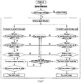
- FIG. 7 is a logical block diagram in which a motor device of a high-voltage switchgear for use in an electric chassis cart judges how the motor operates according to an input external command signal and a collected position signal for the circuit breaker, a opened/closed state signal for the circuit breaker and an opening/closing signal for the ground knife according to a preferred embodiment of the present disclosure.
- the system initialization and overvoltage detection are first performed. If the overvoltage is detected and exceeds a certain threshold, the system is in a locked state. Before the unlocking, the motor cannot start normally whatever conditions are satisfied; if the system overvoltage detection passes, the motor is in a standby state, and it is detected in real time whether there is an external command signal input.
- the motor After the motor is started, during the movement (before reaching a corresponding stop position), the motor still constantly scans its condition signal (the ground knife switch opening signal and the circuit breaker opening signal). So long as one of the conditions is not satisfied, the motor will stop immediately and the signal is locked; when the signal is locked, the system is in a locked state, and no matter what conditions are met before manual unlocking, the motor cannot continue to operate and start normally;
- condition signal the ground knife switch opening signal and the circuit breaker opening signal
- a reset signal is an unlocking signal; after the motor starts, when the motor reaches a corresponding position, namely, the signal conditions satisfy the normal in-position stop, the motor stops and continues to wait for the next command.
- FIG. 8 is a schematic structural view of a motor device of a high-voltage switchgear serving as an energy storage motor of a spring operating mechanism according to a further preferred embodiment of the present disclosure.
- the motor device for the high-voltage switchgear includes a DC brushless motor 20, a drive and control device 30, and a decelerator gear 40.
- the DC brushless motor 20 and the drive and control device 30 are not shown in the figure, and their specific structures may be found from the aforesaid preferred embodiment of the motor device for the high-voltage switchgear for use in an electric chassis cart.
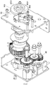
- FIG. 9 is a schematic diagram of overall transmission of a decelerator device of a motor device of a high-voltage switchgear serving as an energy storage motor of a spring operating mechanism according to this embodiment of the present disclosure.
- the energy storage motor employs four-stage transmission, wherein the first stage is through engagement of a worm gear and a worm, and the rotation of the output shaft 208 of the motor is transmitted to a gear transmission system 402; according to an embodiment of the present disclosure, for example, the transmission ratio R1 of the worm gear to the worm in the first stage is 40; at the second stage, the transmission ratio R2 of deceleration transmission is 3.3; at the third stage, the transmission ratio R3 of deceleration transmission is 4; at the fourth stage, the transmission ratio R4 of deceleration transmission is 4.23.
- the deceleration at the second to fourth stages is standard spur gear engagement.
- the desired rotation speed and torque are transmitted via the output shaft to a corresponding load, namely, a spring operating mechanism.
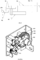
- FIGS. 10A-10B are structural schematic diagrams of a decelerator device of a motor device of a high-voltage switchgear serving as an energy storage motor according to this preferred embodiment of the present disclosure, wherein FIG. 10A is a perspective view, and FIG. 10B is a cross-sectional view;
- the motor device for the high-voltage switchgear further includes a clutch 50 for controlling the coupling and decoupling of the DC brushless motor 20 and the motor load.
- the motor load may vary depending on different application situations.
- the motor load is a circuit breaker chassis cart in the first preferred embodiment.
- the motor load is a spring operating mechanism.
- FIG. 10A further shows a position where the motor device for the high-voltage switchgear is not fully stored with energy.
- the motor drive shaft 208 of the DC brushless motor transmits via the gear drive system 401, and the final output is the output shaft 402.
- the output shaft 402 rotates less than 360° every time the energy storage device performs an operation.
- the force and torque are transmitted to the output shaft 402 by the cooperation of a pin shaft 502 with an output wheel 406 and then through the output wheel.
- FIG. 11 is a schematic diagram showing structures and state switching of a clutch device of a motor device of a high-voltage switchgear serving as an energy storage motor according to this preferred embodiment of the present disclosure.
- the clutch 50 includes a pin shaft 502 and a compression spring 5023.
- the output shaft 402 cannot continue to rotate because the load of the motor device is fully stored with energy; if the motor 20 drives the output wheel 406 to rotate due to inertia or since it is powered off simultaneously, the pin shaft 502 slides along an inner arcuate slot 409.
- the arcuate slot 409 snap-fits the pin shaft 502 into a pin shaft catching slot 4061 on the output wheel 406 and compresses the spring 5023.
- the pin shaft 502 breaks away from the position where the pin shaft 502 snap-fits with the gear transmission system 401 of the decelerator 40, so that the output shaft 402 of the decelerator 40 breaks away from the transmission engagement with the clutch transmission system 401.
- the transmission of the DC brushless motor is no longer transmitted to the output shaft 402.
- the pin shaft 502 When the motor 20 is started again to perform the next energy storage operation, the pin shaft 502 will gradually reset along the inner arc groove 409 under the action of the spring 5023 as the output wheel 406 rotates, until the pin shaft 502 re-snap-fits into the arcuate slot 409, and further drives the output shaft 402 to transmit the corresponding force and torque.
- the motor device of the circuit breaker further includes a power cutoff device for cutting off the power supply to the DC brushless motor 20 when the motor device for the high-voltage switchgear is fully stored with energy.
- FIGS. 12A-12B are comparative schematic diagrams of a clutch device of a motor device of a high-voltage switchgear serving as an energy storage motor before and after the motor is fully stored with energy according to a preferred embodiment of the present disclosure, wherein FIG. 12A is a schematic diagram of normal operation of the motor before the motor is fully stored with energy.
- FIG. 12B is a schematic diagram showing the power supply to the motor being cut off after the motor is fully stored with energy.
- the clutch 50 includes an output cam 503 that fits over the output shaft 402 and rotates with the output shaft 402.
- the output cam 503 is provided with an open notch 5031.
- the motor device for the high-voltage switchgear further includes a motor input signal controller 60 for inputting a start signal, a stop signal, a forward rotation signal and a reverse rotation signal to the DC brushless motor 20.
- the motor input signal controller 60 is connected to an external power supply to supply power to the drive and control device 30; the drive and control device 30 generates the motor control signal of the DC brushless motor 20 based on an external command signal input by the motor input signal controller 60, and based on the position signal for the circuit breaker, the opened/closed state information for the circuit breaker and the opening/closing signal for the ground knife switch.
- the drive and control device 30 further includes a communication module 305 for transmitting parameters of the DC brushless motor 20 to an upper-layer receiving unit.
- the communication module 305 transmits the parameters of the DC brushless motor 20 by serial communication or controller LAN bus communication.
- the communication module 305 adopts a galvanic isolated RS485 mode or CAN field bus mode at the physical layer, and the communication protocol supports Modbus to transmit motor operation data and curves.
- the drive and control device 30 further includes a power supply module 303 adapted to transform a 24V-250V AC and provide a low voltage DC power supply.
- the drive and control device 30 further includes a control module 307 for controlling the semiconductor switch 302 to cut off the power supply to the DC brushless motor 20 when the DC brushless motor 20 is overloaded.
- a monitoring module 308 is configured to detect the external command signal input by the motor input signal controller 60 and the position signal for the circuit breaker, the opened/closed state signal for the circuit breaker and the opening/closing signal for the ground knife switch.
- the monitoring module 308 constantly scans the opening/closing signal for the ground knife switch and the opening/closing signal for the circuit breaker during the operation of the motor device for the high-voltage switchgear.
- the control module 307 When either of the knife switch and the circuit breaker is not in the open state, the control module 307 immediately stops the motor and locks the signal, thereby locking the system.
- the monitoring module 308 detects the external command signal input by the motor input signal controller 60, the handcart is pushed in or pushed out, and the microprocessor 301 judges whether conditions for executing the external command signal action are satisfied. If the conditions are satisfied, the motor executes the corresponding external command signal; if any of the conditions is not satisfied, the motor does not execute the external command signal.
- the control module 307 employs an MCU with strong anti-interference performance and a control current to perform closed-loop motor control.
- the command given by the user is that the handcart is pushed in, at this time it is detected whether the circuit breaker is opened, whether the knife switch is opened and whether the circuit breaker is at a service position. If the three conditions are satisfied at the same time, the motor performs the operation of pushing in the handcart. Otherwise, if any of the conditions is not satisfied, the motor will not perform the operation.
- the command given by the user is that the handcart is pulled out, at this time it is detected whether the circuit breaker is opened, whether the knife switch is opened and whether the circuit breaker is at a test position. If the three conditions are satisfied at the same time, the motor performs the operation of pulling out the handcart. Otherwise, if any of the conditions is not satisfied, the motor will not perform the operation
- the monitoring module 308 also constantly monitors the operating state of the DC brushless motor during operation of the motor. If the current of the DC brushless motor exceeds a specified threshold, e.g., the motor operates at a 24V DC and the current exceeds 2.5A, the drive and control device 30 stops the motor and the system is locked.
- a specified threshold e.g., the motor operates at a 24V DC and the current exceeds 2.5A
- the drive and control device 30 stops the motor and the system is locked.
- a specified threshold e.g., the motor operates at a 24V DC and the current exceeds 2.5A
- the drive and control device 30 stops the motor and the system is locked.
- a specified threshold e.g., the motor operates at a 24V DC and the current exceeds 2.5A
- the drive and control device 30 stops the motor and the system is locked.
- the system After the signal is locked, the system is in the locked state, and it cannot continue to run and start before being manually unlocked or before being powered on again. At this time, the motor cannot operate regardless of pressing operation buttons such as a push-in button and a push-out button.
- the motor device of the present disclosure is free from the complexity of the traditional motor intelligent system.
- the motor device not only can integrate the drive control and communication module with the body of the motor, but also employs electronic commutation without open flames.
- the DC brushless motor has a long lifetime and can usually run continuously for more than 5,000 hours. At the same time, the efficiency of the DC brushless motor is very high, usually up to 70%, whereas the traditional motor can only reach 30%-50%.
- the DC brushless motor has very low vibration and noise and can achieve smooth operation.
- the DC brushless motor has natural advantages: the speed may be regulated via voltage as well as frequency.
- the motor for the intelligent circuit breaker based on the DC brushless motor not only naturally inherits various advantages of the brushless motor, but also has a simple and compact structure, is easy to maintain, and greatly reduces the costs of the whole system while improving the reliability of the overall system, as compared with the motor intelligent system used in the conventional breaker.
- the motor device for the high-voltage switchgear provided by the present disclosure first introduces a DC brushless motor, and secondly, employs an integrated drive and control device, and integrates various functions such as driving, protection, communication, power supply control and power supply. Furthermore, the motor device for the high-voltage switchgear provided by the present disclosure has a decelerator device which is novel and reasonable in design and simple in structure.
- the design of the clutch is also different from a conventional one, it may not only control engagement and disengagement of the drive of the DC brushless motor, but also have a load. When the motor device is fully stored with energy, it may automatically disengage from the transmission system.
- the further optimized design of the clutch may also enable automatic cutoff of the power supply of the DC brushless motor as needed.
Landscapes
- Control Of Motors That Do Not Use Commutators (AREA)
Applications Claiming Priority (1)
| Application Number | Priority Date | Filing Date | Title |
|---|---|---|---|
| PCT/CN2017/083483 WO2018205101A1 (zh) | 2017-05-08 | 2017-05-08 | 高压开关设备的电机装置 |
Publications (3)
| Publication Number | Publication Date |
|---|---|
| EP3624154A1 true EP3624154A1 (de) | 2020-03-18 |
| EP3624154A4 EP3624154A4 (de) | 2020-11-25 |
| EP3624154B1 EP3624154B1 (de) | 2024-07-31 |
Family
ID=64104229
Family Applications (1)
| Application Number | Title | Priority Date | Filing Date |
|---|---|---|---|
| EP17909561.7A Active EP3624154B1 (de) | 2017-05-08 | 2017-05-08 | Motorvorrichtung für hochspannungsschaltvorrichtung |
Country Status (3)
| Country | Link |
|---|---|
| EP (1) | EP3624154B1 (de) |
| CN (1) | CN110574133B (de) |
| WO (1) | WO2018205101A1 (de) |
Families Citing this family (4)
| Publication number | Priority date | Publication date | Assignee | Title |
|---|---|---|---|---|
| DE102018221667A1 (de) | 2018-12-13 | 2020-06-18 | Siemens Aktiengesellschaft | Motorvorrichtung für einen Schalterantrieb eines elektrischen Schalters |
| CN112038195A (zh) * | 2020-10-16 | 2020-12-04 | 无锡伊之维电动科技有限公司 | 具有离合功能的断路器电动操作机构 |
| CN114199589B (zh) * | 2021-12-10 | 2025-01-07 | 江苏现代电力科技股份有限公司 | 一种电动底盘车模拟装置 |
| CN119581284A (zh) * | 2025-02-06 | 2025-03-07 | 浙江阿尔斯通电气有限公司 | 一种采用双向离合的重合闸断路器及操作方法 |
Family Cites Families (19)
| Publication number | Priority date | Publication date | Assignee | Title |
|---|---|---|---|---|
| EP0464644B2 (de) * | 1990-07-06 | 2000-01-05 | Hitachi, Ltd. | Bürstenloser Motor mit eingebautem integriertem Schaltkreis, welcher einen peripheren Schaltkreis mit einem Chip beinhaltet |
| US6107702A (en) * | 1999-03-29 | 2000-08-22 | Siemens Energy & Automation, Inc. | Electrical control module for a circuit breaker stored energy operator assembly |
| CN101145454B (zh) * | 2007-07-26 | 2010-05-19 | 方云祥 | 双电源自动切换开关的机械联锁传动装置 |
| CN101534020B (zh) * | 2009-04-10 | 2011-01-26 | 沈阳工业大学 | 断路器电机操动机构控制装置及控制方法 |
| JP5402310B2 (ja) * | 2009-06-26 | 2014-01-29 | パナソニック株式会社 | モータ駆動装置および圧縮機および冷蔵庫 |
| CN201498912U (zh) * | 2009-08-06 | 2010-06-02 | 范爱平 | 中置式开关柜电动操作装置 |
| CN101794673A (zh) * | 2010-02-24 | 2010-08-04 | 无锡市凯旋电机有限公司 | 一种带热保护器的电动操作机构 |
| CN201655702U (zh) * | 2010-02-24 | 2010-11-24 | 无锡市凯旋电机有限公司 | 一种带热保护器的电动操作机构 |
| CN102543500B (zh) * | 2011-12-31 | 2014-06-11 | 江苏省电力公司苏州供电公司 | 基于无刷直流电机的刀闸控制装置 |
| CN102646541B (zh) * | 2012-04-23 | 2015-12-02 | 陕西得瑞电力设备有限责任公司 | 一种三工位电动弹簧操动机构 |
| CN103247494A (zh) * | 2013-06-01 | 2013-08-14 | 丁云广 | 基于智能开关的槽轮式电动或手动合闸器 |
| DE202014004732U1 (de) * | 2014-06-12 | 2014-07-04 | Brose Fahrzeugteile GmbH & Co. Kommanditgesellschaft, Würzburg | Elektromotor mit Thermosicherung |
| CN104517752A (zh) * | 2014-09-21 | 2015-04-15 | 赵尉宾 | 开关柜用电动、手动一体化操作机构 |
| CN104505275B (zh) * | 2014-12-23 | 2017-09-29 | 苏州未来电器股份有限公司 | 一种开关机构的控制装置 |
| CN104916504B (zh) * | 2015-05-18 | 2017-03-08 | 贵州泰永长征技术股份有限公司 | 一种万能式断路器操作机构用电机储能装置 |
| CN204906000U (zh) * | 2015-08-07 | 2015-12-23 | 江苏力源电气科技有限公司 | 电动底盘车电动接地刀控制装置 |
| CN106531486B (zh) * | 2015-09-15 | 2018-07-27 | 李程程 | 大功率单电机三工位操动机构 |
| CN205385429U (zh) * | 2016-03-03 | 2016-07-13 | 浙江豪顿电气有限公司 | 变压器分接开关输出电压自动调节器的机械装置 |
| CN106340410B (zh) * | 2016-08-16 | 2018-08-17 | 厦门宏发电力电器有限公司 | 一种能够实现触点快速闭合的电机继电器 |
-
2017
- 2017-05-08 CN CN201780090064.7A patent/CN110574133B/zh active Active
- 2017-05-08 EP EP17909561.7A patent/EP3624154B1/de active Active
- 2017-05-08 WO PCT/CN2017/083483 patent/WO2018205101A1/zh not_active Ceased
Also Published As
| Publication number | Publication date |
|---|---|
| EP3624154A4 (de) | 2020-11-25 |
| WO2018205101A1 (zh) | 2018-11-15 |
| EP3624154B1 (de) | 2024-07-31 |
| CN110574133B (zh) | 2022-01-25 |
| CN110574133A (zh) | 2019-12-13 |
Similar Documents
| Publication | Publication Date | Title |
|---|---|---|
| EP3624154B1 (de) | Motorvorrichtung für hochspannungsschaltvorrichtung | |
| CN110211356B (zh) | 一种电器设备的无线遥控智能控制系统 | |
| WO2011097773A1 (zh) | 电子式高压断路器和高压隔离开关互锁的装置 | |
| CN205529536U (zh) | 洗衣机 | |
| CN208890687U (zh) | 电机驱动电路及电器设备 | |
| CN213768275U (zh) | 一种急停控制电路、装置及充电机 | |
| CN103166538B (zh) | 通用型电力驱动多回转式执行机构可逆磁力启动器 | |
| CN202840801U (zh) | 管状直线电机 | |
| CN203588955U (zh) | 一种单相自动重合闸断路器 | |
| CN101334646A (zh) | 一种具有调速和互锁功能的观光缆车应急自动门控制装置 | |
| CN111555663B (zh) | 基于微电机动作的电机启停系统及方法 | |
| CN201178297Y (zh) | 用于家电的电机驱动保护电路 | |
| CN205901644U (zh) | 一种低能耗防来电的保护装置 | |
| CN111769767A (zh) | 一种控制装置 | |
| CN203151406U (zh) | 一种电动帘体的驱动电路和电动帘体 | |
| CN106253765A (zh) | 一种低能耗防来电的保护装置 | |
| CN222088507U (zh) | 电动操作机构和断路器 | |
| CN224232622U (zh) | 断路器以及电力系统 | |
| CN207768236U (zh) | 一种料理机及料理机的电机控制电路 | |
| CN218631878U (zh) | 一种带自我保护断路器的直流分励脱扣器 | |
| CN221854041U (zh) | 一种可交直流转换的电动环链葫芦 | |
| CN206961778U (zh) | 一种通过拨动断路器脱扣杆实现快速脱扣的机构 | |
| CN115083852B (zh) | 断路器传动机构的控制装置及控制方法 | |
| CN223770569U (zh) | 真空垃圾处理机组控制系统 | |
| CN214755512U (zh) | 一种变压器直流偏磁监测与隔离接地装置 |
Legal Events
| Date | Code | Title | Description |
|---|---|---|---|
| STAA | Information on the status of an ep patent application or granted ep patent |
Free format text: STATUS: THE INTERNATIONAL PUBLICATION HAS BEEN MADE |
|
| PUAI | Public reference made under article 153(3) epc to a published international application that has entered the european phase |
Free format text: ORIGINAL CODE: 0009012 |
|
| STAA | Information on the status of an ep patent application or granted ep patent |
Free format text: STATUS: REQUEST FOR EXAMINATION WAS MADE |
|
| 17P | Request for examination filed |
Effective date: 20191108 |
|
| AK | Designated contracting states |
Kind code of ref document: A1 Designated state(s): AL AT BE BG CH CY CZ DE DK EE ES FI FR GB GR HR HU IE IS IT LI LT LU LV MC MK MT NL NO PL PT RO RS SE SI SK SM TR |
|
| AX | Request for extension of the european patent |
Extension state: BA ME |
|
| DAV | Request for validation of the european patent (deleted) | ||
| DAX | Request for extension of the european patent (deleted) | ||
| A4 | Supplementary search report drawn up and despatched |
Effective date: 20201022 |
|
| RIC1 | Information provided on ipc code assigned before grant |
Ipc: H01H 71/70 20060101ALI20201016BHEP Ipc: H01H 3/26 20060101AFI20201016BHEP |
|
| STAA | Information on the status of an ep patent application or granted ep patent |
Free format text: STATUS: EXAMINATION IS IN PROGRESS |
|
| 17Q | First examination report despatched |
Effective date: 20220524 |
|
| GRAP | Despatch of communication of intention to grant a patent |
Free format text: ORIGINAL CODE: EPIDOSNIGR1 |
|
| STAA | Information on the status of an ep patent application or granted ep patent |
Free format text: STATUS: GRANT OF PATENT IS INTENDED |
|
| INTG | Intention to grant announced |
Effective date: 20240228 |
|
| GRAS | Grant fee paid |
Free format text: ORIGINAL CODE: EPIDOSNIGR3 |
|
| GRAA | (expected) grant |
Free format text: ORIGINAL CODE: 0009210 |
|
| STAA | Information on the status of an ep patent application or granted ep patent |
Free format text: STATUS: THE PATENT HAS BEEN GRANTED |
|
| RAP3 | Party data changed (applicant data changed or rights of an application transferred) |
Owner name: ABB SCHWEIZ AG |
|
| AK | Designated contracting states |
Kind code of ref document: B1 Designated state(s): AL AT BE BG CH CY CZ DE DK EE ES FI FR GB GR HR HU IE IS IT LI LT LU LV MC MK MT NL NO PL PT RO RS SE SI SK SM TR |
|
| REG | Reference to a national code |
Ref country code: CH Ref legal event code: EP Ref country code: GB Ref legal event code: FG4D |
|
| REG | Reference to a national code |
Ref country code: DE Ref legal event code: R096 Ref document number: 602017083782 Country of ref document: DE |
|
| REG | Reference to a national code |
Ref country code: IE Ref legal event code: FG4D |
|
| REG | Reference to a national code |
Ref country code: LT Ref legal event code: MG9D |
|
| REG | Reference to a national code |
Ref country code: NL Ref legal event code: MP Effective date: 20240731 |
|
| PG25 | Lapsed in a contracting state [announced via postgrant information from national office to epo] |
Ref country code: PT Free format text: LAPSE BECAUSE OF FAILURE TO SUBMIT A TRANSLATION OF THE DESCRIPTION OR TO PAY THE FEE WITHIN THE PRESCRIBED TIME-LIMIT Effective date: 20241202 |
|
| REG | Reference to a national code |
Ref country code: AT Ref legal event code: MK05 Ref document number: 1709289 Country of ref document: AT Kind code of ref document: T Effective date: 20240731 |
|
| PG25 | Lapsed in a contracting state [announced via postgrant information from national office to epo] |
Ref country code: PT Free format text: LAPSE BECAUSE OF FAILURE TO SUBMIT A TRANSLATION OF THE DESCRIPTION OR TO PAY THE FEE WITHIN THE PRESCRIBED TIME-LIMIT Effective date: 20241202 |
|
| PG25 | Lapsed in a contracting state [announced via postgrant information from national office to epo] |
Ref country code: NO Free format text: LAPSE BECAUSE OF FAILURE TO SUBMIT A TRANSLATION OF THE DESCRIPTION OR TO PAY THE FEE WITHIN THE PRESCRIBED TIME-LIMIT Effective date: 20241031 |
|
| PG25 | Lapsed in a contracting state [announced via postgrant information from national office to epo] |
Ref country code: FI Free format text: LAPSE BECAUSE OF FAILURE TO SUBMIT A TRANSLATION OF THE DESCRIPTION OR TO PAY THE FEE WITHIN THE PRESCRIBED TIME-LIMIT Effective date: 20240731 Ref country code: GR Free format text: LAPSE BECAUSE OF FAILURE TO SUBMIT A TRANSLATION OF THE DESCRIPTION OR TO PAY THE FEE WITHIN THE PRESCRIBED TIME-LIMIT Effective date: 20241101 Ref country code: NL Free format text: LAPSE BECAUSE OF FAILURE TO SUBMIT A TRANSLATION OF THE DESCRIPTION OR TO PAY THE FEE WITHIN THE PRESCRIBED TIME-LIMIT Effective date: 20240731 Ref country code: PL Free format text: LAPSE BECAUSE OF FAILURE TO SUBMIT A TRANSLATION OF THE DESCRIPTION OR TO PAY THE FEE WITHIN THE PRESCRIBED TIME-LIMIT Effective date: 20240731 |
|
| PG25 | Lapsed in a contracting state [announced via postgrant information from national office to epo] |
Ref country code: BG Free format text: LAPSE BECAUSE OF FAILURE TO SUBMIT A TRANSLATION OF THE DESCRIPTION OR TO PAY THE FEE WITHIN THE PRESCRIBED TIME-LIMIT Effective date: 20240731 |
|
| PG25 | Lapsed in a contracting state [announced via postgrant information from national office to epo] |
Ref country code: LV Free format text: LAPSE BECAUSE OF FAILURE TO SUBMIT A TRANSLATION OF THE DESCRIPTION OR TO PAY THE FEE WITHIN THE PRESCRIBED TIME-LIMIT Effective date: 20240731 |
|
| PG25 | Lapsed in a contracting state [announced via postgrant information from national office to epo] |
Ref country code: AT Free format text: LAPSE BECAUSE OF FAILURE TO SUBMIT A TRANSLATION OF THE DESCRIPTION OR TO PAY THE FEE WITHIN THE PRESCRIBED TIME-LIMIT Effective date: 20240731 Ref country code: IS Free format text: LAPSE BECAUSE OF FAILURE TO SUBMIT A TRANSLATION OF THE DESCRIPTION OR TO PAY THE FEE WITHIN THE PRESCRIBED TIME-LIMIT Effective date: 20241130 |
|
| PG25 | Lapsed in a contracting state [announced via postgrant information from national office to epo] |
Ref country code: HR Free format text: LAPSE BECAUSE OF FAILURE TO SUBMIT A TRANSLATION OF THE DESCRIPTION OR TO PAY THE FEE WITHIN THE PRESCRIBED TIME-LIMIT Effective date: 20240731 |
|
| PG25 | Lapsed in a contracting state [announced via postgrant information from national office to epo] |
Ref country code: RS Free format text: LAPSE BECAUSE OF FAILURE TO SUBMIT A TRANSLATION OF THE DESCRIPTION OR TO PAY THE FEE WITHIN THE PRESCRIBED TIME-LIMIT Effective date: 20241031 Ref country code: ES Free format text: LAPSE BECAUSE OF FAILURE TO SUBMIT A TRANSLATION OF THE DESCRIPTION OR TO PAY THE FEE WITHIN THE PRESCRIBED TIME-LIMIT Effective date: 20240731 |
|
| PG25 | Lapsed in a contracting state [announced via postgrant information from national office to epo] |
Ref country code: RS Free format text: LAPSE BECAUSE OF FAILURE TO SUBMIT A TRANSLATION OF THE DESCRIPTION OR TO PAY THE FEE WITHIN THE PRESCRIBED TIME-LIMIT Effective date: 20241031 Ref country code: PL Free format text: LAPSE BECAUSE OF FAILURE TO SUBMIT A TRANSLATION OF THE DESCRIPTION OR TO PAY THE FEE WITHIN THE PRESCRIBED TIME-LIMIT Effective date: 20240731 Ref country code: NO Free format text: LAPSE BECAUSE OF FAILURE TO SUBMIT A TRANSLATION OF THE DESCRIPTION OR TO PAY THE FEE WITHIN THE PRESCRIBED TIME-LIMIT Effective date: 20241031 Ref country code: NL Free format text: LAPSE BECAUSE OF FAILURE TO SUBMIT A TRANSLATION OF THE DESCRIPTION OR TO PAY THE FEE WITHIN THE PRESCRIBED TIME-LIMIT Effective date: 20240731 Ref country code: LV Free format text: LAPSE BECAUSE OF FAILURE TO SUBMIT A TRANSLATION OF THE DESCRIPTION OR TO PAY THE FEE WITHIN THE PRESCRIBED TIME-LIMIT Effective date: 20240731 Ref country code: IS Free format text: LAPSE BECAUSE OF FAILURE TO SUBMIT A TRANSLATION OF THE DESCRIPTION OR TO PAY THE FEE WITHIN THE PRESCRIBED TIME-LIMIT Effective date: 20241130 Ref country code: HR Free format text: LAPSE BECAUSE OF FAILURE TO SUBMIT A TRANSLATION OF THE DESCRIPTION OR TO PAY THE FEE WITHIN THE PRESCRIBED TIME-LIMIT Effective date: 20240731 Ref country code: GR Free format text: LAPSE BECAUSE OF FAILURE TO SUBMIT A TRANSLATION OF THE DESCRIPTION OR TO PAY THE FEE WITHIN THE PRESCRIBED TIME-LIMIT Effective date: 20241101 Ref country code: FI Free format text: LAPSE BECAUSE OF FAILURE TO SUBMIT A TRANSLATION OF THE DESCRIPTION OR TO PAY THE FEE WITHIN THE PRESCRIBED TIME-LIMIT Effective date: 20240731 Ref country code: ES Free format text: LAPSE BECAUSE OF FAILURE TO SUBMIT A TRANSLATION OF THE DESCRIPTION OR TO PAY THE FEE WITHIN THE PRESCRIBED TIME-LIMIT Effective date: 20240731 Ref country code: BG Free format text: LAPSE BECAUSE OF FAILURE TO SUBMIT A TRANSLATION OF THE DESCRIPTION OR TO PAY THE FEE WITHIN THE PRESCRIBED TIME-LIMIT Effective date: 20240731 Ref country code: AT Free format text: LAPSE BECAUSE OF FAILURE TO SUBMIT A TRANSLATION OF THE DESCRIPTION OR TO PAY THE FEE WITHIN THE PRESCRIBED TIME-LIMIT Effective date: 20240731 |
|
| PG25 | Lapsed in a contracting state [announced via postgrant information from national office to epo] |
Ref country code: SM Free format text: LAPSE BECAUSE OF FAILURE TO SUBMIT A TRANSLATION OF THE DESCRIPTION OR TO PAY THE FEE WITHIN THE PRESCRIBED TIME-LIMIT Effective date: 20240731 Ref country code: DK Free format text: LAPSE BECAUSE OF FAILURE TO SUBMIT A TRANSLATION OF THE DESCRIPTION OR TO PAY THE FEE WITHIN THE PRESCRIBED TIME-LIMIT Effective date: 20240731 Ref country code: RO Free format text: LAPSE BECAUSE OF FAILURE TO SUBMIT A TRANSLATION OF THE DESCRIPTION OR TO PAY THE FEE WITHIN THE PRESCRIBED TIME-LIMIT Effective date: 20240731 |
|
| PG25 | Lapsed in a contracting state [announced via postgrant information from national office to epo] |
Ref country code: EE Free format text: LAPSE BECAUSE OF FAILURE TO SUBMIT A TRANSLATION OF THE DESCRIPTION OR TO PAY THE FEE WITHIN THE PRESCRIBED TIME-LIMIT Effective date: 20240731 |
|
| PG25 | Lapsed in a contracting state [announced via postgrant information from national office to epo] |
Ref country code: CZ Free format text: LAPSE BECAUSE OF FAILURE TO SUBMIT A TRANSLATION OF THE DESCRIPTION OR TO PAY THE FEE WITHIN THE PRESCRIBED TIME-LIMIT Effective date: 20240731 |
|
| PG25 | Lapsed in a contracting state [announced via postgrant information from national office to epo] |
Ref country code: IT Free format text: LAPSE BECAUSE OF FAILURE TO SUBMIT A TRANSLATION OF THE DESCRIPTION OR TO PAY THE FEE WITHIN THE PRESCRIBED TIME-LIMIT Effective date: 20240731 Ref country code: SK Free format text: LAPSE BECAUSE OF FAILURE TO SUBMIT A TRANSLATION OF THE DESCRIPTION OR TO PAY THE FEE WITHIN THE PRESCRIBED TIME-LIMIT Effective date: 20240731 |
|
| REG | Reference to a national code |
Ref country code: DE Ref legal event code: R097 Ref document number: 602017083782 Country of ref document: DE |
|
| PLBE | No opposition filed within time limit |
Free format text: ORIGINAL CODE: 0009261 |
|
| STAA | Information on the status of an ep patent application or granted ep patent |
Free format text: STATUS: NO OPPOSITION FILED WITHIN TIME LIMIT |
|
| 26N | No opposition filed |
Effective date: 20250501 |
|
| PGFP | Annual fee paid to national office [announced via postgrant information from national office to epo] |
Ref country code: DE Payment date: 20250521 Year of fee payment: 9 |
|
| PG25 | Lapsed in a contracting state [announced via postgrant information from national office to epo] |
Ref country code: SE Free format text: LAPSE BECAUSE OF FAILURE TO SUBMIT A TRANSLATION OF THE DESCRIPTION OR TO PAY THE FEE WITHIN THE PRESCRIBED TIME-LIMIT Effective date: 20240731 |
|
| REG | Reference to a national code |
Ref country code: CH Ref legal event code: H13 Free format text: ST27 STATUS EVENT CODE: U-0-0-H10-H13 (AS PROVIDED BY THE NATIONAL OFFICE) Effective date: 20251223 |
|
| PG25 | Lapsed in a contracting state [announced via postgrant information from national office to epo] |
Ref country code: LU Free format text: LAPSE BECAUSE OF NON-PAYMENT OF DUE FEES Effective date: 20250508 |
|
| PG25 | Lapsed in a contracting state [announced via postgrant information from national office to epo] |
Ref country code: CH Free format text: LAPSE BECAUSE OF NON-PAYMENT OF DUE FEES Effective date: 20250531 |
|
| GBPC | Gb: european patent ceased through non-payment of renewal fee |
Effective date: 20250508 |
|
| REG | Reference to a national code |
Ref country code: BE Ref legal event code: MM Effective date: 20250531 |
|
| PG25 | Lapsed in a contracting state [announced via postgrant information from national office to epo] |
Ref country code: MC Free format text: LAPSE BECAUSE OF FAILURE TO SUBMIT A TRANSLATION OF THE DESCRIPTION OR TO PAY THE FEE WITHIN THE PRESCRIBED TIME-LIMIT Effective date: 20240731 |
|
| PG25 | Lapsed in a contracting state [announced via postgrant information from national office to epo] |
Ref country code: GB Free format text: LAPSE BECAUSE OF NON-PAYMENT OF DUE FEES Effective date: 20250508 |
|
| PG25 | Lapsed in a contracting state [announced via postgrant information from national office to epo] |
Ref country code: IE Free format text: LAPSE BECAUSE OF NON-PAYMENT OF DUE FEES Effective date: 20250508 |
|
| PG25 | Lapsed in a contracting state [announced via postgrant information from national office to epo] |
Ref country code: BE Free format text: LAPSE BECAUSE OF NON-PAYMENT OF DUE FEES Effective date: 20250531 |
|
| PG25 | Lapsed in a contracting state [announced via postgrant information from national office to epo] |
Ref country code: FR Free format text: LAPSE BECAUSE OF NON-PAYMENT OF DUE FEES Effective date: 20250531 |