EP3624241A1 - Herstellungsverfahren einer ablaufführung eines elektrochemischen reaktors - Google Patents
Herstellungsverfahren einer ablaufführung eines elektrochemischen reaktors Download PDFInfo
- Publication number
- EP3624241A1 EP3624241A1 EP19195407.2A EP19195407A EP3624241A1 EP 3624241 A1 EP3624241 A1 EP 3624241A1 EP 19195407 A EP19195407 A EP 19195407A EP 3624241 A1 EP3624241 A1 EP 3624241A1
- Authority
- EP
- European Patent Office
- Prior art keywords
- ink
- manufacturing
- layer
- shear
- ribs
- Prior art date
- Legal status (The legal status is an assumption and is not a legal conclusion. Google has not performed a legal analysis and makes no representation as to the accuracy of the status listed.)
- Granted
Links
Images



Classifications
-
- H—ELECTRICITY
- H01—ELECTRIC ELEMENTS
- H01M—PROCESSES OR MEANS, e.g. BATTERIES, FOR THE DIRECT CONVERSION OF CHEMICAL ENERGY INTO ELECTRICAL ENERGY
- H01M8/00—Fuel cells; Manufacture thereof
- H01M8/06—Combination of fuel cells with means for production of reactants or for treatment of residues
- H01M8/0606—Combination of fuel cells with means for production of reactants or for treatment of residues with means for production of gaseous reactants
- H01M8/0656—Combination of fuel cells with means for production of reactants or for treatment of residues with means for production of gaseous reactants by electrochemical means
-
- H—ELECTRICITY
- H01—ELECTRIC ELEMENTS
- H01M—PROCESSES OR MEANS, e.g. BATTERIES, FOR THE DIRECT CONVERSION OF CHEMICAL ENERGY INTO ELECTRICAL ENERGY
- H01M8/00—Fuel cells; Manufacture thereof
- H01M8/02—Details
- H01M8/0202—Collectors; Separators, e.g. bipolar separators; Interconnectors
-
- H—ELECTRICITY
- H01—ELECTRIC ELEMENTS
- H01M—PROCESSES OR MEANS, e.g. BATTERIES, FOR THE DIRECT CONVERSION OF CHEMICAL ENERGY INTO ELECTRICAL ENERGY
- H01M8/00—Fuel cells; Manufacture thereof
- H01M8/02—Details
- H01M8/0202—Collectors; Separators, e.g. bipolar separators; Interconnectors
- H01M8/0258—Collectors; Separators, e.g. bipolar separators; Interconnectors characterised by the configuration of channels, e.g. by the flow field of the reactant or coolant
-
- B—PERFORMING OPERATIONS; TRANSPORTING
- B41—PRINTING; LINING MACHINES; TYPEWRITERS; STAMPS
- B41M—PRINTING, DUPLICATING, MARKING, OR COPYING PROCESSES; COLOUR PRINTING
- B41M1/00—Inking and printing with a printer's forme
- B41M1/12—Stencil printing; Silk-screen printing
-
- C—CHEMISTRY; METALLURGY
- C09—DYES; PAINTS; POLISHES; NATURAL RESINS; ADHESIVES; COMPOSITIONS NOT OTHERWISE PROVIDED FOR; APPLICATIONS OF MATERIALS NOT OTHERWISE PROVIDED FOR
- C09D—COATING COMPOSITIONS, e.g. PAINTS, VARNISHES OR LACQUERS; FILLING PASTES; CHEMICAL PAINT OR INK REMOVERS; INKS; CORRECTING FLUIDS; WOODSTAINS; PASTES OR SOLIDS FOR COLOURING OR PRINTING; USE OF MATERIALS THEREFOR
- C09D11/00—Inks
- C09D11/02—Printing inks
- C09D11/03—Printing inks characterised by features other than the chemical nature of the binder
-
- C—CHEMISTRY; METALLURGY
- C09—DYES; PAINTS; POLISHES; NATURAL RESINS; ADHESIVES; COMPOSITIONS NOT OTHERWISE PROVIDED FOR; APPLICATIONS OF MATERIALS NOT OTHERWISE PROVIDED FOR
- C09D—COATING COMPOSITIONS, e.g. PAINTS, VARNISHES OR LACQUERS; FILLING PASTES; CHEMICAL PAINT OR INK REMOVERS; INKS; CORRECTING FLUIDS; WOODSTAINS; PASTES OR SOLIDS FOR COLOURING OR PRINTING; USE OF MATERIALS THEREFOR
- C09D11/00—Inks
- C09D11/02—Printing inks
- C09D11/10—Printing inks based on artificial resins
- C09D11/102—Printing inks based on artificial resins containing macromolecular compounds obtained by reactions other than those only involving unsaturated carbon-to-carbon bonds
-
- C—CHEMISTRY; METALLURGY
- C09—DYES; PAINTS; POLISHES; NATURAL RESINS; ADHESIVES; COMPOSITIONS NOT OTHERWISE PROVIDED FOR; APPLICATIONS OF MATERIALS NOT OTHERWISE PROVIDED FOR
- C09D—COATING COMPOSITIONS, e.g. PAINTS, VARNISHES OR LACQUERS; FILLING PASTES; CHEMICAL PAINT OR INK REMOVERS; INKS; CORRECTING FLUIDS; WOODSTAINS; PASTES OR SOLIDS FOR COLOURING OR PRINTING; USE OF MATERIALS THEREFOR
- C09D11/00—Inks
- C09D11/52—Electrically conductive inks
-
- H—ELECTRICITY
- H01—ELECTRIC ELEMENTS
- H01M—PROCESSES OR MEANS, e.g. BATTERIES, FOR THE DIRECT CONVERSION OF CHEMICAL ENERGY INTO ELECTRICAL ENERGY
- H01M4/00—Electrodes
- H01M4/86—Inert electrodes with catalytic activity, e.g. for fuel cells
- H01M4/88—Processes of manufacture
-
- H—ELECTRICITY
- H01—ELECTRIC ELEMENTS
- H01M—PROCESSES OR MEANS, e.g. BATTERIES, FOR THE DIRECT CONVERSION OF CHEMICAL ENERGY INTO ELECTRICAL ENERGY
- H01M8/00—Fuel cells; Manufacture thereof
- H01M8/02—Details
- H01M8/0202—Collectors; Separators, e.g. bipolar separators; Interconnectors
- H01M8/0258—Collectors; Separators, e.g. bipolar separators; Interconnectors characterised by the configuration of channels, e.g. by the flow field of the reactant or coolant
- H01M8/026—Collectors; Separators, e.g. bipolar separators; Interconnectors characterised by the configuration of channels, e.g. by the flow field of the reactant or coolant characterised by grooves, e.g. their pitch or depth
-
- H—ELECTRICITY
- H01—ELECTRIC ELEMENTS
- H01M—PROCESSES OR MEANS, e.g. BATTERIES, FOR THE DIRECT CONVERSION OF CHEMICAL ENERGY INTO ELECTRICAL ENERGY
- H01M8/00—Fuel cells; Manufacture thereof
- H01M8/02—Details
- H01M8/0202—Collectors; Separators, e.g. bipolar separators; Interconnectors
- H01M8/0267—Collectors; Separators, e.g. bipolar separators; Interconnectors having heating or cooling means, e.g. heaters or coolant flow channels
-
- H—ELECTRICITY
- H01—ELECTRIC ELEMENTS
- H01M—PROCESSES OR MEANS, e.g. BATTERIES, FOR THE DIRECT CONVERSION OF CHEMICAL ENERGY INTO ELECTRICAL ENERGY
- H01M8/00—Fuel cells; Manufacture thereof
- H01M8/10—Fuel cells with solid electrolytes
- H01M8/1016—Fuel cells with solid electrolytes characterised by the electrolyte material
- H01M8/1018—Polymeric electrolyte materials
- H01M8/1067—Polymeric electrolyte materials characterised by their physical properties, e.g. porosity, ionic conductivity or thickness
-
- H—ELECTRICITY
- H01—ELECTRIC ELEMENTS
- H01M—PROCESSES OR MEANS, e.g. BATTERIES, FOR THE DIRECT CONVERSION OF CHEMICAL ENERGY INTO ELECTRICAL ENERGY
- H01M8/00—Fuel cells; Manufacture thereof
- H01M8/10—Fuel cells with solid electrolytes
- H01M8/1016—Fuel cells with solid electrolytes characterised by the electrolyte material
- H01M8/1018—Polymeric electrolyte materials
- H01M8/1069—Polymeric electrolyte materials characterised by the manufacturing processes
-
- H—ELECTRICITY
- H01—ELECTRIC ELEMENTS
- H01M—PROCESSES OR MEANS, e.g. BATTERIES, FOR THE DIRECT CONVERSION OF CHEMICAL ENERGY INTO ELECTRICAL ENERGY
- H01M8/00—Fuel cells; Manufacture thereof
- H01M8/10—Fuel cells with solid electrolytes
- H01M2008/1095—Fuel cells with polymeric electrolytes
-
- H—ELECTRICITY
- H01—ELECTRIC ELEMENTS
- H01M—PROCESSES OR MEANS, e.g. BATTERIES, FOR THE DIRECT CONVERSION OF CHEMICAL ENERGY INTO ELECTRICAL ENERGY
- H01M8/00—Fuel cells; Manufacture thereof
- H01M8/002—Shape, form of a fuel cell
-
- Y—GENERAL TAGGING OF NEW TECHNOLOGICAL DEVELOPMENTS; GENERAL TAGGING OF CROSS-SECTIONAL TECHNOLOGIES SPANNING OVER SEVERAL SECTIONS OF THE IPC; TECHNICAL SUBJECTS COVERED BY FORMER USPC CROSS-REFERENCE ART COLLECTIONS [XRACs] AND DIGESTS
- Y02—TECHNOLOGIES OR APPLICATIONS FOR MITIGATION OR ADAPTATION AGAINST CLIMATE CHANGE
- Y02E—REDUCTION OF GREENHOUSE GAS [GHG] EMISSIONS, RELATED TO ENERGY GENERATION, TRANSMISSION OR DISTRIBUTION
- Y02E60/00—Enabling technologies; Technologies with a potential or indirect contribution to GHG emissions mitigation
- Y02E60/30—Hydrogen technology
- Y02E60/50—Fuel cells
Definitions
- the invention relates to electrochemical reactors with membrane-electrode assemblies, such as fuel cells with a proton exchange membrane.
- the invention relates in particular to optimizing the process for manufacturing components of a fuel cell and reducing the weight of these components.
- Fuel cells are for example envisaged as an electrical power system for motor vehicles produced on a large scale in the future, as well as for a large number of applications.
- a fuel cell is an electrochemical device that converts chemical energy directly into electrical energy.
- a fuel such as dihydrogen or methanol is used as fuel for the fuel cell.
- Proton exchange membrane fuel cells operate at low temperature, typically below 250 ° C. and have particularly advantageous compactness properties.
- Each cell includes an electrolytic membrane allowing only the passage of protons and not the passage of electrons.
- the membrane comprises an anode on a first face and a cathode on a second face to form a membrane / electrode assembly called AME.
- the hydrogen is ionized to produce protons crossing the membrane.
- the electrons produced by this reaction migrate towards an anodic plate, electronic conductor, then cross an electric circuit external to the cell to form an electric current.
- oxygen is reduced and reacts with the protons to form water and close the electrical circuit with the other so-called cathode plate.
- Each electrode must be supplied with reagents continuously and as homogeneously as possible.
- flow channels are conventionally present on the anode and cathode plates.
- porous electronic conductive materials are usually placed between the flow channels of the plates and each of the electrodes to produce a gas diffusion layer also called GDL typically produced by a network of carbon fibers.
- this generally includes several stacked electrochemical cells electrically connected in series.
- the fuel cell can then comprise several plates provided with flow channels, for example made of metal, stacked on one another.
- the membrane is arranged between at least one anode plate and at least one cathode plate.
- the flow plates may include flow channels and orifices for guiding the reagents and products to / from the membrane, for guiding coolant depending on the power of the fuel cell, and for separating different compartments.
- the plates provided with flow channels continuously supply the reactive surfaces of the electrodes with reagents, as they are consumed.
- the plates comprise networks of flow channels ensuring the distribution of the reagents in the reactive zones.
- the networks of flow channels are connected between inlet and outlet collectors, generally passing through the stack right through. Each collector is surrounded by a seal to avoid mixing of the various fluids circulating in the stack.
- the plates are also electrically conductive to form collectors of the electrons generated at the anode.
- the plates also have a mechanical function for transmitting the tightening forces of the stack, necessary for the quality of the electrical contact, and a mechanical holding function for the electrochemical core.
- An electronic conduction is produced through the plates, an ionic conduction being obtained through the membrane.
- a plate provided with flow channels can be produced by machining a solid block in order to define these flow channels.
- the machined block is generally made of graphite.
- a set of plates is formed from two metal sheets assembled by welding and generally providing between them channels for the flow of a coolant.
- the shape of the flow channels is then defined by forming or deformation of the sheets, for example by stamping the metal sheets.
- Such a design is generally favored in order to reduce the cost and the bulk of the plates while maintaining good performance.
- the sheets used generally have a thickness of between 0.1 and 4mm, depending on whether the channels are stamped or machined.
- the flow channels produced by stamping a sheet with a typical thickness of 0.1 mm usually have a width of between 0.4 and 2 mm, for a depth of between 0.2 and 0.4 mm.
- anode and cathode plate sheets prove to be both complex and relatively expensive. This strongly impacts the cost price of the fuel cell, of which the set of plates constitutes one of the main costs.
- the stamping operations induce losses of flatness, which make the deposition of gasket complicated.
- the set of plates thus obtained proves to be relatively heavy and bulky, which is particularly troublesome for on-board applications of the fuel cell.
- the thin sheets used remain flexible enough to allow the assembly of generally non-planar shapes.
- the document CN107394228 proposes to deposit one or more layers of an ink including carbon on a flat metal sheet, so as to form ribs, flow channels being delimited between these ribs.
- the document US2003 / 198860 describes the application of an electrode in the form of a paste having a non-Newtonian behavior on a membrane or on a gaseous diffusion layer of support.
- the problem here is to apply the paste with the right viscosity with a nozzle, so as not to have too fluid a flow at the level of this nozzle, and so as to maintain a good distribution of the paste on the support.
- viscosity and shear rate quantities will correspond to a temperature of 20 ° C.
- the invention also relates to the following variants. Those skilled in the art will understand that each of the characteristics of the following variants can be combined independently with the above characteristics, without however constituting an intermediate generalization.
- the step of printing the ink layer on the first face of the substrate is carried out by screen printing.
- said step of printing by screen printing comprises depositing the ink on a screen of the stencil type and applying a doctor blade on the screen so as to apply a shear on the ink for the print on the first side of the substrate.
- the method further comprises a drying step to solidify the ink layer of the pattern formed.
- said step of printing the ink layer comprises the application of a shear stress on this layer with a shear speed of between 10 s -1 and 80 s -1 .
- said layer of printed ink has a thickness at least equal to 150 ⁇ m.
- the ribs formed have a height at least equal to half their width.
- said printed ink includes graphite particles in a proportion of between 90 and 99% of the dry extract.
- the dry extract represents between 50 and 75% by weight of the ink on which the shear is applied.
- said ink includes particles having a diameter between 1 and 6 ⁇ m D50 in a proportion between 1 and 35% by weight dry extract of graphite mixture, said ink further including particles having a diameter between 10 and 25 ⁇ m D50 in a proportion of at least 25% by weight of the dry extract of graphite mixture.
- said ink on which the shear is applied includes a polymeric binder.
- said ink to which the shear is applied includes polyvinylidene fluoride.
- the ink on which the shear is applied has a conservation modulus greater than the viscous modulus for a deformation amplitude of 1% at a frequency less than 0.1 Hz,
- the ink on which the shear is applied has a conservation modulus lower than the viscous modulus for a deformation amplitude of 1% at a frequency greater than 2 Hz.
- said supplied substrate is free of relief at the level of the printed ink.
- said supplied substrate is an electrically conductive plate, a gas diffusion layer or an electrode layer.
- the invention also relates to a method for manufacturing a bipolar plate, comprising the production of first to third flow guides by a manufacturing method as defined above, said supplied substrate being an electrically conductive plate for each of the first to third flow guides, a layer of electrically conductive ink being printed only on the first face of the first to third flow guides, a bipolar plate being formed by joining second faces of the first and second flow guides and by joining the ribs of the pattern formed on the second flow guide against a second face of the third flow guide, so as to delimit flow channels between the second and third flow guides.
- said supplied substrate is an electrically conductive plate
- a layer of electrically conductive ink is printed by applying a shear of this layer on a second face of said conductive plate, the viscosity of the printed ink being between 70 and 500 Pa.s for a shear rate of 0.1 s -1 , and the viscosity of the printed ink being between 2.5 and 7 Pa. s for a shear speed of 100 s -1 , the ink layer being printed to form a pattern including ribs delimiting flow channels.
- a flow guide in a method of manufacturing a bipolar plate, can be produced by a manufacturing method as defined above, and comprising the application of one face of another electrically conductive plate against ribs of a pattern formed on the support of the flow guide.
- each of said ribs of the patterns formed consists of a single layer of printed ink.
- the plate is produced by a method according to any one of the preceding claims.
- orientation or positioning 'center', 'top', 'bottom', 'front', 'rear', 'left', 'right', 'vertical', 'horizontal', 'top', 'bottom', 'inside' or 'outside' is based on that which can be seen from the attached drawings. These terms are used to facilitate understanding of the description of the invention, rather than to induce that an element described with a particular orientation or position must necessarily be produced or implemented with this specific orientation or position.
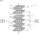
- the figure 1 is a schematic exploded perspective view of a stack of cells 1 of a fuel cell 4.
- the fuel cell 4 comprises several cells 1 superimposed.
- Cells 1 are of the proton exchange membrane or polymer electrolyte membrane type.
- the invention will be detailed here for the manufacture of a flow guide for reagents, products or heat transfer fluids for a fuel cell, but may also be used for the manufacture of flow guides for other types of electrochemical reactors. , for example an electrolyser.
- the fuel cell 4 comprises a fuel source 40.
- the fuel source 40 here supplies dihydrogen to an inlet of each cell 1.
- the fuel cell 4 also includes a fuel source 42.
- the fuel source 42 here supplies air an inlet to each cell 1, the oxygen in the air being used as an oxidant.
- Each cell 1 also includes exhaust channels.
- One or more cells 1 also have a cooling circuit for the reactive zone.
- Each cell 1 comprises a membrane / electrodes 110 or AME 110 assembly.
- a membrane / electrodes 110 assembly comprises a solid electrolyte 113, a cathode (not shown) and an anode 111 placed on either side of the electrolyte and fixed on this electrolyte 113.
- the electrolyte layer 113 forms a semi-permeable membrane allowing proton conduction while being impermeable to the gases present in the cell.
- the electrolyte layer also prevents passage of electrons between the anode 111 and the cathode.
- the electrolyte 113 is for example made of polybenzimidazole (PBI) doped with phosphoric acid or of a proton conducting ionomer.
- a set of anode and cathode plates 5 is arranged.
- a set of plates provided with channels 5 forms a reagent flow guide.
- Each set of plates 5 here defines anode flow channels and cathode flow channels on opposite external faces.
- Flow plate assemblies 5 also advantageously define coolant flow channels between two successive membrane / electrode assemblies.
- the plate assemblies 5 can each be formed in a manner known per se from two assembled conductive metal sheets, for example stainless steel, titanium alloy, aluminum alloy, nickel alloy or tantalum alloy. Each sheet then defines a respective external face.
- the plate assemblies 5 can also be obtained by any other method, for example molding or injection from carbon-polymer composites.
- Each membrane / electrode assembly 110 may further include a gas diffusion layer (not shown) disposed between the anode and fuel flow channels, and another gas diffusion layer disposed between the cathode and other oxidizer flow channels.
- the membrane / electrode 110 assemblies may include reinforcements, not illustrated here. In this embodiment, the envisaged channels are produced on the plates.
- a cell 1 of the fuel cell 4 usually generates a DC voltage between the anode and the cathode between 0.5 and 1V, depending on the gas flow conditions.
- the oxidant source 42 typically comprises a compressor for introducing air at a given pressure at the inlet of the cells 1.
- a compressor receives for example an air pressure setpoint, the air pressure being able to be regulated by a variable compressor speed.
- the stack of plate assemblies 5 and membrane / electrode assemblies 110 is intended to form a plurality of flow collectors. To this end, respective orifices are formed through the plate assemblies 5 and through the membrane / electrode assemblies 110. The orifices of the plate assemblies 5 and membrane / electrode assemblies 110 are arranged opposite so as to form the different flow collectors.
- the figure 2 is a top view of an example of a flow guide plate 2.
- the figure 2 illustrates a face of the guide plate 2, intended to guide a reagent in a reactive zone positioned in its middle part.
- the guide plate 2 thus comprises a reactive zone 21 in its middle part, comprising flow channels 211.
- the guide plate 2 also comprises an inlet manifold 24 of the reagent and an outlet manifold 25 of the reagent, positioned on either side of hot spot 21.
- a zone homogenization 22 is formed between the reactive zone 21 and the inlet manifold 24.
- the homogenization zone 22 here comprises homogenization channels 221.
- a connection zone 241, including for example injectors, is formed between the inlet manifold 24 and the homogenization zone 22.
- a homogenization zone 23 is provided between the reactive zone 21 and the outlet collector 25.
- the homogenization zone 23 here comprises homogenization channels 231.
- a zone connection, including for example injectors, is formed between the outlet manifold 25 and the
- Such a manufacturing process makes it possible to produce relatively high ribs in a single printing step, with good control over their final geometry.
- Such a manufacturing process makes it possible for example to produce ribs delimiting the final height of the flow channels in a single printing step.
- an ink comprising such shear-thinning properties makes it possible to make this ink very fluid during the application of the shear in order to conform to the face of the conductive plate and follow the desired printing pattern, then to find this very viscous ink afterwards. stopping the application of shear to maintain good geometric control of the ribs formed during printing. In particular, the risks of creep phenomena are limited before the ribs formed harden.
- the figure 3 illustrates a particular case of printing a layer of conductive ink by a screen printing process.
- the method is illustrated here in its application to the example of a conductive plate but could also be applied to a gas diffusion layer or to an electrode.
- the figure 3 is a schematic representation in side section of a screen printing step for the formation of a guide plate according to an embodiment of the invention.
- Screen printing is advantageous because it allows a high production rate, for example with a screen printing speed of between 15 and 25 meters / minute for a screen printing technique by rotation.
- An electrically conductive plate 20 is here positioned and held in position on a support 91, such as a conveyor plate.
- a frame 92 is positioned above the plate 20.
- the mask 93 is arranged vertically of the plate 20 at the level of this middle opening of the frame 92.
- the mask 93 can have a structure known per se for implementing a screen printing step.
- the mask 93 may for example be in the form of a mesh screen (designated by mesh in English) or be in the form of a stencil screen (designated by stencil in English).
- a stencil-type screen may be favored for depositing a greater quantity or a greater thickness of ink 30.
- An ink layer 30 having the shear thinning properties detailed above is deposited on the mask 93, vertically the plate 20.
- the ink layer 30 deposited is then in a very viscous and frozen state.
- a doctor blade 94 is then pressed against the ink 30 until the mask 93 is brought into contact with the plate 20.
- the doctor blade 94 then traverses the surface of the plate 20, to apply a shear stress on the ink 30.
- the shear speed applied by the doctor blade 94 on the ink 30 may for example reach 50 s -1 .
- the application of the shear on the ink 30 thins it, which allows it to pass through the pattern of the mask 93 by matching the shape of the latter, to be transferred to the plate 20.
- the ink transferred to the plate 20 forms a pattern including ribs 31, delimiting flow channels 32 therebetween.
- the ribs 31 in particular have lateral faces extending along a dimension of the plate 20, to form flow channels 32.
- the ribs 31 formed may be continuous or discontinuous, of the same size or not all along the flow .
- a step of drying the ink is advantageously carried out, in order to remove the solvent present in the ink 30. Drying can be carried out by natural evaporation or accelerated by artificial irradiation. Accelerated drying can promote better control geometric of the ribs 31 formed. Accelerated drying can for example be carried out in a continuous oven or in a static oven. Drying can be carried out simultaneously on several sheets after having assembled them.
- a calendering of the ribs 31 can for example be carried out after drying, either to limit the flatness defects of the top of the ribs, or to densify their structure and increase their electronic conductivity.
- the formation of the ribs 31 on a plate 20 makes it possible to use a particularly thin plate 20.
- a thin plate makes it possible both to increase the density of electrical power generated for a given mass of the fuel cell 4 and to reduce the manufacturing cost of the fuel cell 4.
- a radius of curvature can be applied to the plate 20 to have a fuel cell 4 of non-planar shape.
- the printing area of the ink layer is advantageously devoid of relief.
- the ribs 31 formed define flow channels 32 in order to be able to form, for example, one of the modes of circulation of reagents mentioned above.
- the ribs 31 can also be formed to delimit flow channels in homogenization zones.
- the formulation of the ink 30 deposited on which the shear is applied is even more advantageously configured to exhibit the properties following: an ink viscosity between 200 and 400 Pa.s for a shear speed of 0.1 s -1 , and the ink viscosity being between 4.5 and 6 Pa.s for a speed 100 s -1 shear.
- an ink having the following properties makes it possible in particular to promote good fluidity during the application of the shear, and good stability after the formation of the pattern of ribs 31.
- the ink advantageously has a preservation module G '(or elastic module according to a common name) greater than the loss module G "(or viscous module according to the current name) to low frequencies, typically less than 0.1 Hz. This property indicates that the ink is stable and remains frozen at rest and therefore presents a reduced risk of sedimentation or creep.
- this ink advantageously has a conservation module G ′ lower than the loss module G ′′ at higher frequencies, typically greater than 2 Hz.
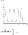
- the diagram of the figure 10 illustrates the values G 'and G "for an ink exhibiting such behavior, with the frequency of deformation on the abscissa and the value of the module on the ordinate.
- the values of the conservation module G' and of the loss module G" are preferably included between 1 and 200 Pa, more favorably between 10 and 100 Pa, at a frequency of 0.1 Hz.
- the ink deposited 30, for example in the form of an electron-conducting paste, here includes a conductive material, a polymeric binder and a solvent.
- the proportions of conductive material, binder and solvent make it possible to adjust the rheology of the ink 30.
- the conductive material of the ink 30 is for example graphite.
- the use of graphite proves to be advantageous because of its hydrophobic properties, suitable for operation in a very humid environment such as that of a fuel cell.
- the ink includes for example graphite with more than 50% by weight of dry extract.
- the graphite included in the ink 30 to be printed is for example natural or synthetic graphite, surface modified graphite, shaped graphite spherical or patatoid (or "flake" in English).
- the graphite included in the ink 30 to be printed has for example a particle size distribution of between 1 and 30 ⁇ m for the D50, and more favorably between 3 and 15 ⁇ m for the D50.
- the ink 30 advantageously includes particles of graphite of at least two different sizes, in order to improve the mechanical strength and the conductivity of the ribs 31.
- the geometric dispersions of the ribs 31 (and therefore of the flow channels 32) are formed also reduced.
- the ink 30 advantageously includes particles of graphite having a diameter of between 1 and 6 ⁇ m D50 in a proportion of between 1 and 35% by weight of the dry extract of graphite mixture (preferably between 15 and 27%, advantageously of 25%), the ink 30 further including graphite particles having a diameter between 10 and 25 ⁇ m D50 in a proportion of at least 25% by weight of the dry extract of graphite mixture.
- the percentage of dry extract of the ink 30 is preferably between 50 and 75%, more favorably between 58 and 62%.
- the ink 30 advantageously includes a mass proportion of graphite of between 90 and 99% of the solid mass of the dry extract, preferably a mass proportion of between 96 and 98% of the dry extract. With such proportions, a reduced shrinkage of the ribs 31 is obtained on drying and excellent geometric stability after printing.
- Additives can be added to the ink to improve its electronic conductivity: for example electronic conductors such as carbon black, carbon fibers or carbon nanotubes or else metallic fibers such as silver nanowires, copper nanowires , or nanowires of any other conductive metal.
- electronic conductors such as carbon black, carbon fibers or carbon nanotubes or else metallic fibers such as silver nanowires, copper nanowires , or nanowires of any other conductive metal.
- PVdF polyvinylidene fluoride
- PMMA polymethyl methacrylate
- POE polyoxyethylene
- PET polyethylene terephthalate
- polyacrylics or their derivatives polyimides or their derivatives
- polyetheretherketones or their derivatives polyethersulfone or their derivatives
- polyolefins polyethylene, celluloses such as, inter alia, carboxymethylcellulose or cellulose fibers, copolymers such as inter alia PVdF-HFP (hexafluoropropylene) or PVdF-POE, acrylic latexes or Latex type SBR (for stryrene butadiene rubber in English for styrene-butadiene rubber) or NBR (for nitrile butadiene rubber in English for butadiene nitride nitride
- SBR for stryrene butadiene rubber in English for styrene-butadiene rubber
- NBR for nitrile buta
- the polymeric binder of the ink used is PVdF.
- PVdF is insoluble in water, which is of great interest for operation in a fuel cell, in which water is produced in large quantities.
- PVdF is hydrophobic and therefore contributes to the evacuation of the water produced towards the outside of the fuel cell to unclog the flow channels of the reactive zone.
- the percentage of solvent is preferably between 30 and 50% of the total mass of the ink 30, more favorably between 38 and 42% of the total mass of the ink 30.
- NMP N-methyl-2-pyrrolidone
- cyclic ethers such as dioxane or tetrahydrofuran (THF), N, N-dimethylformamide (DMF) , N, N-dimethylacetamide (DMAc), dimethyl sulfoxide (DMSO), metacresol, ketones such as acetone, methyl ethyl ketone (MEK) or its derivatives, water or aqueous bases.
- NMP N-methyl-2-pyrrolidone
- THF N, N-dimethylformamide
- DMAc N, N-dimethylacetamide
- MEK dimethyl sulfoxide
- MEK dimethyl sulfoxide
- MEK methyl ethyl ketone
- additives can be used to homogenize the ink, also called colloidal suspension, such as surfactants, dispersants or deflocculating agents.
- the plate 20 can for example be made of metal covered with carbon or of a composite loaded with metal.
- the plate 20 can for example include stainless steel, aluminum, or titanium.
- the metal may for example be protected by a carbon or metallized deposit or an electron-conducting composite polymer including a metallization layer, to protect the plate 20 against corrosion or to reduce contact resistances.
- the plate 20 can be flexible or rigid and preferably have a thickness between 0.01 and 1 mm, more favorably between 0.02 and 0.1 mm.
- the manufacturing process proves to be particularly suitable for the formation of ribs 31 with a height at least equal to 120 ⁇ m, or even a height at least equal to 200 ⁇ m, or even at least 250 ⁇ m, in a single layer of ink. printed.
- the height of the ribs 31 formed in a single layer of printed ink may for example be between 140 and 200 ⁇ m.
- the invention proves to be particularly advantageous for the formation of ribs 31 of a height at least equal to half their width, and even more advantageous when their height is at least equal to their width.
- the spacing between the ribs 31, which defines the width of the flow channels 32 has for example a value between 200 and 400 ⁇ m, preferably between 250 and 300 ⁇ m (spacing measured at mid-height of the ribs 31).
- the figure 11 illustrates in a comparative manner polarization curves of a fuel cell including flow guide plates produced by the manufacturing method of the invention and of a fuel cell including flow guide plates produced by machining of a graphite block. There is a very great similarity of performance between these fuel cells, which shows that a flow guide plate manufactured by a method according to the invention does not degrade the operation of the fuel cell.
- the figure 12 illustrates an example of profile of ribs 31 and homogenization channels 32, measured for a flow guide plate 2 produced according to a manufacturing method of the invention.
- the ribs 31 thus obtained have a fairly homogeneous structure and have reduced geometric dispersions therebetween.
- the parameters of the process which allowed the formation of such ribs are the following: a screen printing machine sold by the company DEK under the reference model 248 was used.
- a flat plate of golden stainless steel with a thickness of 0.05 mm thick was used.
- the print motif is made up of 0.4mm wide by 50mm long openings spaced 0.4mm apart.
- the stencil screen used has a thickness of 0.2mm.
- the shear was applied at a speed of 50mm / s at a force of 4kg.
- the printed pattern was then dried for one hour at a temperature of 80 ° C in a ventilated study.
- the ink used comprises 56.6% by mass of a mixture of graphite particles having two different diameters (75% of the graphite having a diameter of 13 ⁇ m D50, 25% of the graphite having a diameter of 4 ⁇ m D50), 2 , 4% by mass of PVdF, and 41% by mass of NMP.
- the manufacturing process can be implemented on an opposite face of the plate 20, with the same ink and printing parameters.
- the figures 4 to 6 illustrate (schematic sectional views) different configurations of guide plates 2, for which ribs have been formed by printing on two opposite faces.
- ribs 31 are formed on an upper face 201 of the plate 20 and other ribs 31 are formed on a lower face 202 of the plate 20.
- Flow channels 32 are formed between the ribs 31.
- the ribs 31 of the two opposite faces extend in parallel.
- the ribs of the two faces 201 and 202 have the same dimensions and are superimposed: the ribs of the two faces are symmetrical to each other with respect to the plate 20.
- ribs 31 are formed on an upper face 201 of the plate 20 and other ribs 31 are formed on a lower face 202 of the plate 20.
- Flow channels 32 are formed between the ribs 31.
- the ribs 31 of the two opposite faces extend in parallel, in a longitudinal direction.
- the ribs of the two faces 201 and 202 have the same dimensions and are offset in a transverse direction.
- ribs 31 are formed on an upper face 201 of the plate 20 and other ribs 33 are formed on a underside 202 of the plate 20.
- Flow channels 32 are formed between the ribs 31.
- Non-illustrated flow channels are also formed between the ribs 33.
- the ribs 31 and the ribs 33 extend in perpendicular directions.
- the figure 7 illustrates a bipolar plate, formed by the superposition of flow guide plates obtained by a manufacturing method according to the invention.
- three flow guide plates are superimposed. These three flow guide plates have ribs 31 on a single face.
- the upper guide plate has ribs 31 projecting from its upper face.
- the intermediate guide plate and the lower guide plate have ribs 31 projecting from their underside.
- flow channels 32 of a reagent are formed between the ribs of the upper plate
- flow channels 34 of a heat transfer liquid are formed between the ribs of the guide plate intermediate
- flow channels 35 of another reagent are provided between the ribs of the bottom plate.
- the figure 8 illustrates a bipolar plate, formed by the superposition of flow guide plates obtained by a manufacturing method according to the invention.
- the upper guide plate corresponds to the configuration illustrated in figure 4 .
- This guide plate therefore has ribs 31 projecting from its two faces.
- the flow guide plate has ribs 31 projecting from a single face.
- the lower guide plate has ribs 31 projecting from its lower face.
- the figure 13 is a schematic sectional view of a guide plate according to a second embodiment of the invention.
- the substrate on which the conductive ink layer is printed by screen printing is here a gas diffusion layer 60.
- the ink can be printed on one face 601 of the gas diffusion layer 60, with parameters similar to those described for the first embodiment.
- the impression then arrives at the formation of ribs 31 delimiting flow channels 32 therebetween.
- the figure 14 is a schematic sectional view of such a guide plate, associated with other components of an electrochemical reactor.
- a flat conductive plate 20, such as that detailed in the first embodiment, can be pressed against the top of the ribs 31.
- a membrane-electrode assembly, including a membrane 113, an anode 111 and a cathode 112, is pressed against a face 602 of the gas diffusion layer.
- the figure 15 is a schematic sectional view of a guide plate according to a third embodiment of the invention.
- the substrate on which the conductive ink layer is printed by screen printing is here an electrode 111.
- the electrode 111 is in this case an anode but the printing could also be carried out on a cathode.
- the printing is carried out on an electrode 111 secured beforehand to a proton exchange membrane 113 of a membrane-electrode assembly.
- the ink can be printed on one face of the electrode 111, with parameters similar to those described for the first embodiment. The impression then arrives at the formation of ribs 31 delimiting flow channels 32 therebetween.
- the figure 16 is a schematic sectional view of such a guide plate, associated with other components of an electrochemical reactor.
- a flat conductive plate 20, such as that detailed in the first embodiment, can be pressed against the top of the ribs 31.
Landscapes
- Chemical & Material Sciences (AREA)
- Engineering & Computer Science (AREA)
- Life Sciences & Earth Sciences (AREA)
- Chemical Kinetics & Catalysis (AREA)
- Manufacturing & Machinery (AREA)
- General Chemical & Material Sciences (AREA)
- Electrochemistry (AREA)
- Sustainable Development (AREA)
- Sustainable Energy (AREA)
- Materials Engineering (AREA)
- Wood Science & Technology (AREA)
- Organic Chemistry (AREA)
- Fuel Cell (AREA)
- Physical Or Chemical Processes And Apparatus (AREA)
Applications Claiming Priority (1)
| Application Number | Priority Date | Filing Date | Title |
|---|---|---|---|
| FR1871024A FR3085800B1 (fr) | 2018-09-12 | 2018-09-12 | Procede de fabrication d’un guide d’ecoulement de reacteur electrochimique |
Publications (2)
| Publication Number | Publication Date |
|---|---|
| EP3624241A1 true EP3624241A1 (de) | 2020-03-18 |
| EP3624241B1 EP3624241B1 (de) | 2021-07-14 |
Family
ID=65494424
Family Applications (1)
| Application Number | Title | Priority Date | Filing Date |
|---|---|---|---|
| EP19195407.2A Active EP3624241B1 (de) | 2018-09-12 | 2019-09-04 | Herstellungsverfahren einer ablaufführung eines elektrochemischen reaktors |
Country Status (6)
| Country | Link |
|---|---|
| US (1) | US11437638B2 (de) |
| EP (1) | EP3624241B1 (de) |
| JP (1) | JP7486931B2 (de) |
| KR (1) | KR20200030470A (de) |
| CN (1) | CN110896146A (de) |
| FR (1) | FR3085800B1 (de) |
Cited By (2)
| Publication number | Priority date | Publication date | Assignee | Title |
|---|---|---|---|---|
| EP4016678A1 (de) * | 2020-12-21 | 2022-06-22 | Commissariat à l'Energie Atomique et aux Energies Alternatives | Verfahren zur herstellung einer ablaufführung mit strukturiertem kanal für elektrochemischen reaktor |
| FR3118319A1 (fr) * | 2020-12-21 | 2022-06-24 | Commissariat A L'energie Atomique Et Aux Energies Alternatives | Procédé de fabrication d’un guide d’écoulement pour réacteur électrochimique |
Families Citing this family (7)
| Publication number | Priority date | Publication date | Assignee | Title |
|---|---|---|---|---|
| FR3117275B1 (fr) | 2020-12-08 | 2023-06-09 | Commissariat Energie Atomique | Plaque bipolaire imprimé pour réacteur électrochimique |
| KR102485280B1 (ko) * | 2021-07-13 | 2023-01-09 | 한국생산기술연구원 | 화학반응기 유닛, 이를 포함하는 조립식 화학반응기 및 이의 제조방법 |
| FR3129786A1 (fr) | 2021-11-30 | 2023-06-02 | Commissariat A L'energie Atomique Et Aux Energies Alternatives | Procédé de fabrication d’un guide d’écoulement pour réacteur électrochimique, et guide d’écoulement associé |
| FR3131458B1 (fr) * | 2021-12-23 | 2023-12-22 | Commissariat Energie Atomique | Procédé de fabrication d’un guide d’écoulement pour réacteur électrochimique |
| FR3131459B1 (fr) * | 2021-12-23 | 2024-02-16 | Commissariat Energie Atomique | Procédé de fabrication d’un guide d’écoulement pour réacteur électrochimique |
| DE202024103284U1 (de) * | 2024-06-18 | 2025-09-25 | Exentis Knowledge Gmbh | Druckpaste |
| DE202024103283U1 (de) * | 2024-06-18 | 2025-09-25 | Exentis Knowledge Gmbh | Druckpaste |
Citations (3)
| Publication number | Priority date | Publication date | Assignee | Title |
|---|---|---|---|---|
| US20030198860A1 (en) | 2001-03-07 | 2003-10-23 | Matsushita Electric Industrial Co., Ltd. | Polymer electrolyte fuel cell and production method of the same |
| CN107394228A (zh) | 2017-08-25 | 2017-11-24 | 新奥科技发展有限公司 | 一种双极板及其制备方法 |
| US20180190998A1 (en) | 2014-12-19 | 2018-07-05 | Zeon Corporation | Electrically conductive ink |
Family Cites Families (8)
| Publication number | Priority date | Publication date | Assignee | Title |
|---|---|---|---|---|
| GB9808524D0 (en) * | 1998-04-23 | 1998-06-17 | British Gas Plc | Fuel cell flow-field structure formed by layer deposition |
| JP2002270189A (ja) * | 2001-03-07 | 2002-09-20 | Matsushita Electric Ind Co Ltd | 高分子電解質型燃料電池の製造方法とこれを用いた高分子電解質型燃料電池 |
| US20040107869A1 (en) * | 2002-12-10 | 2004-06-10 | 3M Innovative Properties Company | Catalyst ink |
| JP2005263859A (ja) * | 2004-03-16 | 2005-09-29 | Sumitomo Rubber Ind Ltd | 導電性インキペースト |
| JP2007026934A (ja) * | 2005-07-19 | 2007-02-01 | Kyocera Corp | 導電性ペースト及びそれを用いて作製される太陽電池素子 |
| JP2008135274A (ja) * | 2006-11-28 | 2008-06-12 | Toyota Motor Corp | 燃料電池の製造方法 |
| US20100099026A1 (en) * | 2008-10-20 | 2010-04-22 | Samsung Electronics Co., Ltd. | Electrode ink composition for ink-jet printing, and electrode and secondary battery manufactured by using the same |
| JP6074978B2 (ja) * | 2012-09-25 | 2017-02-08 | 凸版印刷株式会社 | 燃料電池用膜電極接合体の製造方法および固体高分子形燃料電池の製造方法 |
-
2018
- 2018-09-12 FR FR1871024A patent/FR3085800B1/fr not_active Expired - Fee Related
-
2019
- 2019-09-04 EP EP19195407.2A patent/EP3624241B1/de active Active
- 2019-09-11 US US16/567,108 patent/US11437638B2/en active Active
- 2019-09-11 KR KR1020190112599A patent/KR20200030470A/ko not_active Ceased
- 2019-09-11 CN CN201910857404.5A patent/CN110896146A/zh active Pending
- 2019-09-11 JP JP2019165460A patent/JP7486931B2/ja active Active
Patent Citations (3)
| Publication number | Priority date | Publication date | Assignee | Title |
|---|---|---|---|---|
| US20030198860A1 (en) | 2001-03-07 | 2003-10-23 | Matsushita Electric Industrial Co., Ltd. | Polymer electrolyte fuel cell and production method of the same |
| US20180190998A1 (en) | 2014-12-19 | 2018-07-05 | Zeon Corporation | Electrically conductive ink |
| CN107394228A (zh) | 2017-08-25 | 2017-11-24 | 新奥科技发展有限公司 | 一种双极板及其制备方法 |
Cited By (4)
| Publication number | Priority date | Publication date | Assignee | Title |
|---|---|---|---|---|
| EP4016678A1 (de) * | 2020-12-21 | 2022-06-22 | Commissariat à l'Energie Atomique et aux Energies Alternatives | Verfahren zur herstellung einer ablaufführung mit strukturiertem kanal für elektrochemischen reaktor |
| FR3118319A1 (fr) * | 2020-12-21 | 2022-06-24 | Commissariat A L'energie Atomique Et Aux Energies Alternatives | Procédé de fabrication d’un guide d’écoulement pour réacteur électrochimique |
| FR3118320A1 (fr) * | 2020-12-21 | 2022-06-24 | Commissariat A L'energie Atomique Et Aux Energies Alternatives | Procédé de fabrication d’un guide d’écoulement à canal structuré pour réacteur électrochimique |
| US12500247B2 (en) | 2020-12-21 | 2025-12-16 | Commissariat A L'energie Atomique Et Aux Energies Alternatives | Method of manufacturing a flow guide for an electrochemical reactor |
Also Published As
| Publication number | Publication date |
|---|---|
| CN110896146A (zh) | 2020-03-20 |
| FR3085800A1 (fr) | 2020-03-13 |
| US20200083551A1 (en) | 2020-03-12 |
| JP7486931B2 (ja) | 2024-05-20 |
| EP3624241B1 (de) | 2021-07-14 |
| FR3085800B1 (fr) | 2021-06-04 |
| US11437638B2 (en) | 2022-09-06 |
| KR20200030470A (ko) | 2020-03-20 |
| JP2020057600A (ja) | 2020-04-09 |
Similar Documents
| Publication | Publication Date | Title |
|---|---|---|
| EP3624241B1 (de) | Herstellungsverfahren einer ablaufführung eines elektrochemischen reaktors | |
| US8481185B2 (en) | Catalyst layers to enhance uniformity of current density in membrane electrode assemblies | |
| EP2704241B1 (de) | Verfahren zur Herstellung einer Brennstoffzelle mit Elektroden/Membran-Einheit | |
| EP2768055B1 (de) | Bipolare metallplatte für brennstoffzelle mit protonenaustauschmembran | |
| EP3170220B1 (de) | Bipolare platte für elektrochemischen reaktor mit kompaktem homogenisierungsbereich und geringer druckdifferenz | |
| FR3079675A1 (fr) | Plaque collectrice ayant un revetement anticorrosion | |
| US11283082B2 (en) | Gas diffusion electrode and production method therefor | |
| EP3175502B1 (de) | Elektrochemischer reaktor, der den ladungsverlust der homogeneisierenden zonen der kathode/ der anode ausgleicht | |
| WO2023187103A1 (fr) | Procédé de fabrication d'une plaque bipolaire en fibres de carbone | |
| EP3195391B1 (de) | Brennstoffzelle zur erkennung eines schadstoffes | |
| EP2800825B1 (de) | Poröse elektrode für protonenaustauschmembran | |
| JP2010282975A (ja) | 燃料電池及び燃料電池を製造する方法 | |
| EP3686976A1 (de) | Bipolarplatte zum homogenisieren der temperaturen von kühlflüssigkeit | |
| Wang et al. | Enabling fast-charging of lithium-ion batteries through printed electrodes | |
| EP2867947B1 (de) | Verfahren zur herstellung einer elektroden-/protonenaustauschmembrananordnung | |
| FR3117275A1 (fr) | Plaque bipolaire imprimé pour réacteur électrochimique | |
| WO2014033283A1 (fr) | Pile a combustible limitant le phenomene de corrosion | |
| EP4016677A1 (de) | Verfahren zur herstellung einer ablaufführung für elektrochemischen reaktor | |
| EP3127179B1 (de) | Brennstoffzelle mit optimiertem betrieb | |
| EP4187652A1 (de) | Verfahren zur herstellung eines strömungsleiters für einen elektrochemischen reaktor und strömungsführung dafür | |
| CN117501481A (zh) | 用于受控地引导反应流体的电池复合体 | |
| FR3019685A1 (fr) | Plaque d'ecoulement metallique pour pile a combustible, et son procede de preparation | |
| FR2973580A1 (fr) | Pile a combustible a membrane d'echange de protons presentant une duree de vie accrue | |
| FR3012681A1 (fr) | Pile a combustible a fonctionnement optimise le long du canal d'ecoulement d'air |
Legal Events
| Date | Code | Title | Description |
|---|---|---|---|
| PUAI | Public reference made under article 153(3) epc to a published international application that has entered the european phase |
Free format text: ORIGINAL CODE: 0009012 |
|
| STAA | Information on the status of an ep patent application or granted ep patent |
Free format text: STATUS: REQUEST FOR EXAMINATION WAS MADE |
|
| 17P | Request for examination filed |
Effective date: 20190904 |
|
| AK | Designated contracting states |
Kind code of ref document: A1 Designated state(s): AL AT BE BG CH CY CZ DE DK EE ES FI FR GB GR HR HU IE IS IT LI LT LU LV MC MK MT NL NO PL PT RO RS SE SI SK SM TR |
|
| AX | Request for extension of the european patent |
Extension state: BA ME |
|
| GRAP | Despatch of communication of intention to grant a patent |
Free format text: ORIGINAL CODE: EPIDOSNIGR1 |
|
| STAA | Information on the status of an ep patent application or granted ep patent |
Free format text: STATUS: GRANT OF PATENT IS INTENDED |
|
| INTG | Intention to grant announced |
Effective date: 20210209 |
|
| GRAS | Grant fee paid |
Free format text: ORIGINAL CODE: EPIDOSNIGR3 |
|
| GRAA | (expected) grant |
Free format text: ORIGINAL CODE: 0009210 |
|
| STAA | Information on the status of an ep patent application or granted ep patent |
Free format text: STATUS: THE PATENT HAS BEEN GRANTED |
|
| AK | Designated contracting states |
Kind code of ref document: B1 Designated state(s): AL AT BE BG CH CY CZ DE DK EE ES FI FR GB GR HR HU IE IS IT LI LT LU LV MC MK MT NL NO PL PT RO RS SE SI SK SM TR |
|
| REG | Reference to a national code |
Ref country code: GB Ref legal event code: FG4D Free format text: NOT ENGLISH |
|
| REG | Reference to a national code |
Ref country code: IE Ref legal event code: FG4D Free format text: LANGUAGE OF EP DOCUMENT: FRENCH |
|
| REG | Reference to a national code |
Ref country code: DE Ref legal event code: R096 Ref document number: 602019006080 Country of ref document: DE |
|
| REG | Reference to a national code |
Ref country code: AT Ref legal event code: REF Ref document number: 1411349 Country of ref document: AT Kind code of ref document: T Effective date: 20210815 |
|
| REG | Reference to a national code |
Ref country code: LT Ref legal event code: MG9D |
|
| REG | Reference to a national code |
Ref country code: NL Ref legal event code: MP Effective date: 20210714 |
|
| REG | Reference to a national code |
Ref country code: AT Ref legal event code: MK05 Ref document number: 1411349 Country of ref document: AT Kind code of ref document: T Effective date: 20210714 |
|
| PG25 | Lapsed in a contracting state [announced via postgrant information from national office to epo] |
Ref country code: RS Free format text: LAPSE BECAUSE OF FAILURE TO SUBMIT A TRANSLATION OF THE DESCRIPTION OR TO PAY THE FEE WITHIN THE PRESCRIBED TIME-LIMIT Effective date: 20210714 Ref country code: SE Free format text: LAPSE BECAUSE OF FAILURE TO SUBMIT A TRANSLATION OF THE DESCRIPTION OR TO PAY THE FEE WITHIN THE PRESCRIBED TIME-LIMIT Effective date: 20210714 Ref country code: ES Free format text: LAPSE BECAUSE OF FAILURE TO SUBMIT A TRANSLATION OF THE DESCRIPTION OR TO PAY THE FEE WITHIN THE PRESCRIBED TIME-LIMIT Effective date: 20210714 Ref country code: FI Free format text: LAPSE BECAUSE OF FAILURE TO SUBMIT A TRANSLATION OF THE DESCRIPTION OR TO PAY THE FEE WITHIN THE PRESCRIBED TIME-LIMIT Effective date: 20210714 Ref country code: AT Free format text: LAPSE BECAUSE OF FAILURE TO SUBMIT A TRANSLATION OF THE DESCRIPTION OR TO PAY THE FEE WITHIN THE PRESCRIBED TIME-LIMIT Effective date: 20210714 Ref country code: BG Free format text: LAPSE BECAUSE OF FAILURE TO SUBMIT A TRANSLATION OF THE DESCRIPTION OR TO PAY THE FEE WITHIN THE PRESCRIBED TIME-LIMIT Effective date: 20211014 Ref country code: LT Free format text: LAPSE BECAUSE OF FAILURE TO SUBMIT A TRANSLATION OF THE DESCRIPTION OR TO PAY THE FEE WITHIN THE PRESCRIBED TIME-LIMIT Effective date: 20210714 Ref country code: HR Free format text: LAPSE BECAUSE OF FAILURE TO SUBMIT A TRANSLATION OF THE DESCRIPTION OR TO PAY THE FEE WITHIN THE PRESCRIBED TIME-LIMIT Effective date: 20210714 Ref country code: NO Free format text: LAPSE BECAUSE OF FAILURE TO SUBMIT A TRANSLATION OF THE DESCRIPTION OR TO PAY THE FEE WITHIN THE PRESCRIBED TIME-LIMIT Effective date: 20211014 Ref country code: NL Free format text: LAPSE BECAUSE OF FAILURE TO SUBMIT A TRANSLATION OF THE DESCRIPTION OR TO PAY THE FEE WITHIN THE PRESCRIBED TIME-LIMIT Effective date: 20210714 Ref country code: PT Free format text: LAPSE BECAUSE OF FAILURE TO SUBMIT A TRANSLATION OF THE DESCRIPTION OR TO PAY THE FEE WITHIN THE PRESCRIBED TIME-LIMIT Effective date: 20211115 |
|
| PG25 | Lapsed in a contracting state [announced via postgrant information from national office to epo] |
Ref country code: PL Free format text: LAPSE BECAUSE OF FAILURE TO SUBMIT A TRANSLATION OF THE DESCRIPTION OR TO PAY THE FEE WITHIN THE PRESCRIBED TIME-LIMIT Effective date: 20210714 Ref country code: LV Free format text: LAPSE BECAUSE OF FAILURE TO SUBMIT A TRANSLATION OF THE DESCRIPTION OR TO PAY THE FEE WITHIN THE PRESCRIBED TIME-LIMIT Effective date: 20210714 Ref country code: GR Free format text: LAPSE BECAUSE OF FAILURE TO SUBMIT A TRANSLATION OF THE DESCRIPTION OR TO PAY THE FEE WITHIN THE PRESCRIBED TIME-LIMIT Effective date: 20211015 |
|
| REG | Reference to a national code |
Ref country code: DE Ref legal event code: R097 Ref document number: 602019006080 Country of ref document: DE |
|
| PG25 | Lapsed in a contracting state [announced via postgrant information from national office to epo] |
Ref country code: DK Free format text: LAPSE BECAUSE OF FAILURE TO SUBMIT A TRANSLATION OF THE DESCRIPTION OR TO PAY THE FEE WITHIN THE PRESCRIBED TIME-LIMIT Effective date: 20210714 |
|
| PLBE | No opposition filed within time limit |
Free format text: ORIGINAL CODE: 0009261 |
|
| REG | Reference to a national code |
Ref country code: BE Ref legal event code: MM Effective date: 20210930 |
|
| STAA | Information on the status of an ep patent application or granted ep patent |
Free format text: STATUS: NO OPPOSITION FILED WITHIN TIME LIMIT |
|
| PG25 | Lapsed in a contracting state [announced via postgrant information from national office to epo] |
Ref country code: SM Free format text: LAPSE BECAUSE OF FAILURE TO SUBMIT A TRANSLATION OF THE DESCRIPTION OR TO PAY THE FEE WITHIN THE PRESCRIBED TIME-LIMIT Effective date: 20210714 Ref country code: SK Free format text: LAPSE BECAUSE OF FAILURE TO SUBMIT A TRANSLATION OF THE DESCRIPTION OR TO PAY THE FEE WITHIN THE PRESCRIBED TIME-LIMIT Effective date: 20210714 Ref country code: RO Free format text: LAPSE BECAUSE OF FAILURE TO SUBMIT A TRANSLATION OF THE DESCRIPTION OR TO PAY THE FEE WITHIN THE PRESCRIBED TIME-LIMIT Effective date: 20210714 Ref country code: MC Free format text: LAPSE BECAUSE OF FAILURE TO SUBMIT A TRANSLATION OF THE DESCRIPTION OR TO PAY THE FEE WITHIN THE PRESCRIBED TIME-LIMIT Effective date: 20210714 Ref country code: EE Free format text: LAPSE BECAUSE OF FAILURE TO SUBMIT A TRANSLATION OF THE DESCRIPTION OR TO PAY THE FEE WITHIN THE PRESCRIBED TIME-LIMIT Effective date: 20210714 Ref country code: CZ Free format text: LAPSE BECAUSE OF FAILURE TO SUBMIT A TRANSLATION OF THE DESCRIPTION OR TO PAY THE FEE WITHIN THE PRESCRIBED TIME-LIMIT Effective date: 20210714 Ref country code: AL Free format text: LAPSE BECAUSE OF FAILURE TO SUBMIT A TRANSLATION OF THE DESCRIPTION OR TO PAY THE FEE WITHIN THE PRESCRIBED TIME-LIMIT Effective date: 20210714 |
|
| 26N | No opposition filed |
Effective date: 20220419 |
|
| PG25 | Lapsed in a contracting state [announced via postgrant information from national office to epo] |
Ref country code: LU Free format text: LAPSE BECAUSE OF NON-PAYMENT OF DUE FEES Effective date: 20210904 Ref country code: IT Free format text: LAPSE BECAUSE OF FAILURE TO SUBMIT A TRANSLATION OF THE DESCRIPTION OR TO PAY THE FEE WITHIN THE PRESCRIBED TIME-LIMIT Effective date: 20210714 Ref country code: IE Free format text: LAPSE BECAUSE OF NON-PAYMENT OF DUE FEES Effective date: 20210904 Ref country code: BE Free format text: LAPSE BECAUSE OF NON-PAYMENT OF DUE FEES Effective date: 20210930 |
|
| REG | Reference to a national code |
Ref country code: CH Ref legal event code: PL |
|
| PG25 | Lapsed in a contracting state [announced via postgrant information from national office to epo] |
Ref country code: CY Free format text: LAPSE BECAUSE OF FAILURE TO SUBMIT A TRANSLATION OF THE DESCRIPTION OR TO PAY THE FEE WITHIN THE PRESCRIBED TIME-LIMIT Effective date: 20210714 |
|
| PG25 | Lapsed in a contracting state [announced via postgrant information from national office to epo] |
Ref country code: LI Free format text: LAPSE BECAUSE OF NON-PAYMENT OF DUE FEES Effective date: 20220930 Ref country code: HU Free format text: LAPSE BECAUSE OF FAILURE TO SUBMIT A TRANSLATION OF THE DESCRIPTION OR TO PAY THE FEE WITHIN THE PRESCRIBED TIME-LIMIT; INVALID AB INITIO Effective date: 20190904 Ref country code: CH Free format text: LAPSE BECAUSE OF NON-PAYMENT OF DUE FEES Effective date: 20220930 |
|
| PG25 | Lapsed in a contracting state [announced via postgrant information from national office to epo] |
Ref country code: MK Free format text: LAPSE BECAUSE OF FAILURE TO SUBMIT A TRANSLATION OF THE DESCRIPTION OR TO PAY THE FEE WITHIN THE PRESCRIBED TIME-LIMIT Effective date: 20210714 |
|
| PG25 | Lapsed in a contracting state [announced via postgrant information from national office to epo] |
Ref country code: MT Free format text: LAPSE BECAUSE OF FAILURE TO SUBMIT A TRANSLATION OF THE DESCRIPTION OR TO PAY THE FEE WITHIN THE PRESCRIBED TIME-LIMIT Effective date: 20210714 |
|
| PGFP | Annual fee paid to national office [announced via postgrant information from national office to epo] |
Ref country code: DE Payment date: 20250919 Year of fee payment: 7 |
|
| PGFP | Annual fee paid to national office [announced via postgrant information from national office to epo] |
Ref country code: GB Payment date: 20250923 Year of fee payment: 7 |
|
| PGFP | Annual fee paid to national office [announced via postgrant information from national office to epo] |
Ref country code: FR Payment date: 20250924 Year of fee payment: 7 |
|
| PG25 | Lapsed in a contracting state [announced via postgrant information from national office to epo] |
Ref country code: TR Free format text: LAPSE BECAUSE OF FAILURE TO SUBMIT A TRANSLATION OF THE DESCRIPTION OR TO PAY THE FEE WITHIN THE PRESCRIBED TIME-LIMIT Effective date: 20210714 |