EP3624275B1 - Borne de connexion - Google Patents
Borne de connexion Download PDFInfo
- Publication number
- EP3624275B1 EP3624275B1 EP19196214.1A EP19196214A EP3624275B1 EP 3624275 B1 EP3624275 B1 EP 3624275B1 EP 19196214 A EP19196214 A EP 19196214A EP 3624275 B1 EP3624275 B1 EP 3624275B1
- Authority
- EP
- European Patent Office
- Prior art keywords
- connection body
- male connection
- wall surface
- side protruding
- inlet
- Prior art date
- Legal status (The legal status is an assumption and is not a legal conclusion. Google has not performed a legal analysis and makes no representation as to the accuracy of the status listed.)
- Active
Links
Images




Classifications
-
- H—ELECTRICITY
- H01—ELECTRIC ELEMENTS
- H01R—ELECTRICALLY-CONDUCTIVE CONNECTIONS; STRUCTURAL ASSOCIATIONS OF A PLURALITY OF MUTUALLY-INSULATED ELECTRICAL CONNECTING ELEMENTS; COUPLING DEVICES; CURRENT COLLECTORS
- H01R13/00—Details of coupling devices of the kinds covered by groups H01R12/70 or H01R24/00 - H01R33/00
- H01R13/02—Contact members
- H01R13/15—Pins, blades or sockets having separate spring member for producing or increasing contact pressure
- H01R13/187—Pins, blades or sockets having separate spring member for producing or increasing contact pressure with spring member in the socket
-
- H—ELECTRICITY
- H01—ELECTRIC ELEMENTS
- H01R—ELECTRICALLY-CONDUCTIVE CONNECTIONS; STRUCTURAL ASSOCIATIONS OF A PLURALITY OF MUTUALLY-INSULATED ELECTRICAL CONNECTING ELEMENTS; COUPLING DEVICES; CURRENT COLLECTORS
- H01R13/00—Details of coupling devices of the kinds covered by groups H01R12/70 or H01R24/00 - H01R33/00
- H01R13/40—Securing contact members in or to a base or case; Insulating of contact members
- H01R13/42—Securing in a demountable manner
-
- H—ELECTRICITY
- H01—ELECTRIC ELEMENTS
- H01R—ELECTRICALLY-CONDUCTIVE CONNECTIONS; STRUCTURAL ASSOCIATIONS OF A PLURALITY OF MUTUALLY-INSULATED ELECTRICAL CONNECTING ELEMENTS; COUPLING DEVICES; CURRENT COLLECTORS
- H01R13/00—Details of coupling devices of the kinds covered by groups H01R12/70 or H01R24/00 - H01R33/00
- H01R13/02—Contact members
- H01R13/193—Means for increasing contact pressure at the end of engagement of coupling part, e.g. zero insertion force or no friction
-
- H—ELECTRICITY
- H01—ELECTRIC ELEMENTS
- H01R—ELECTRICALLY-CONDUCTIVE CONNECTIONS; STRUCTURAL ASSOCIATIONS OF A PLURALITY OF MUTUALLY-INSULATED ELECTRICAL CONNECTING ELEMENTS; COUPLING DEVICES; CURRENT COLLECTORS
- H01R13/00—Details of coupling devices of the kinds covered by groups H01R12/70 or H01R24/00 - H01R33/00
- H01R13/62—Means for facilitating engagement or disengagement of coupling parts or for holding them in engagement
-
- H—ELECTRICITY
- H01—ELECTRIC ELEMENTS
- H01R—ELECTRICALLY-CONDUCTIVE CONNECTIONS; STRUCTURAL ASSOCIATIONS OF A PLURALITY OF MUTUALLY-INSULATED ELECTRICAL CONNECTING ELEMENTS; COUPLING DEVICES; CURRENT COLLECTORS
- H01R13/00—Details of coupling devices of the kinds covered by groups H01R12/70 or H01R24/00 - H01R33/00
- H01R13/02—Contact members
- H01R13/04—Pins or blades for co-operation with sockets
- H01R13/05—Resilient pins or blades
- H01R13/052—Resilient pins or blades co-operating with sockets having a circular transverse section
-
- H—ELECTRICITY
- H01—ELECTRIC ELEMENTS
- H01R—ELECTRICALLY-CONDUCTIVE CONNECTIONS; STRUCTURAL ASSOCIATIONS OF A PLURALITY OF MUTUALLY-INSULATED ELECTRICAL CONNECTING ELEMENTS; COUPLING DEVICES; CURRENT COLLECTORS
- H01R13/00—Details of coupling devices of the kinds covered by groups H01R12/70 or H01R24/00 - H01R33/00
- H01R13/02—Contact members
- H01R13/10—Sockets for co-operation with pins or blades
- H01R13/11—Resilient sockets
- H01R13/111—Resilient sockets co-operating with pins having a circular transverse section
Definitions
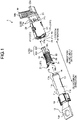
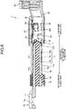
- the male connection body 11 is formed in such a manner that the periphery of an insulating portion 10a extending in the axial direction is covered with a conductive tubular member 10b (see FIG. 6 ).
- the male connection body 11 has a tip end portion 14 on a front end side (a front side in the insertion direction).
- the tip end portion 14 of the embodiment is formed by a portion of the insulating portion 10a exposed through a front end side end portion of the tubular member 10b.
- the tip end portion 14 is formed in a tapered shape, and is formed such that the diameter thereof increases from the front end side to a back end side (a back side in the insertion direction).
- the inlet-side protruding portions 25 are guided into the first recessed portions 13 along the first inclined surfaces 13a of the first recessed portions 13.
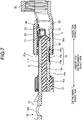
- the outer wall surface 11d of the male connection body 11 starts contacting the first contact point portion 30a.
- FIG. 10 is a perspective view illustrating a male terminal of the variation of the embodiment.
- FIG. 11 is a sectional view illustrating the process of inserting the male connection body into the housing space in the variation of the embodiment.
- FIG. 12 is a sectional view illustrating the process of inserting the male connection body into the housing space in the variation of the embodiment.
- FIG. 13 is a sectional view illustrating the process of inserting the male connection body into the housing space in the variation of the embodiment.
- FIGS. 11 to 13 are the sectional views each corresponding to FIGS. 6 to 8 in the above-described embodiment.
Landscapes
- Details Of Connecting Devices For Male And Female Coupling (AREA)
- Connector Housings Or Holding Contact Members (AREA)
Claims (4)
- Borne de connexion (1) comprenant :un corps de connexion femelle tubulaire (21) présentant une conductivité et comportant un espace de logement (HS) qui s'étend en direction axiale ;un corps de connexion mâle (11) présentant une conductivité et configuré pour être inséré dans l'espace de logement (HS) à une position de réalisation de raccord en direction axiale ; eten élément élastique (30) supporté par une surface de paroi interne (21c) du corps de connexion femelle (21) entourant l'espace de logement (HS), ayant une portion de point de contact (30a) configurée pour entrer en contact avec une surface de paroi externe (11d) du corps de connexion mâle (11) et pour compresser le corps de connexion mâle (11),dans laquellele corps de connexion femelle (21) comporte une portion saillante côté éloigné (24) qui ressort depuis une position de la surface de paroi interne (21c) sur un côté éloigné en direction d'insertion par rapport à la portion de point de contact (30a), et une portion saillante côté entrée (25) qui ressort depuis une position de la surface de paroi interne (21c) sur un côté d'entrée en direction d'insertion par rapport à la portion de point de contact (30a),la portion saillante côté éloigné (24) et la portion saillante côté entrée (25) sont configurées pour supporter la surface de paroi externe (11d) du corps de connexion mâle (11) à la position de réalisation de raccord contre la force de compression de l'élément élastique (30), etla surface de paroi externe (11d) du corps de connexion mâle (11) comporte une première portion renfoncée (13) formée dans une portion qui fait face à la portion saillante côté entrée (25) de telle sorte que quand le corps de connexion mâle (11) est inséré dans l'espace de logement (HS), la portion saillante côté entrée (25) dépasse la première portion renfoncée (13),caractérisée en ce que la première portion renfoncée (13), sur la surface de paroi externe (11d) du corps de connexion mâle (11), est formée en direction d'insertion à une portion intermédiaire (11c) entre une portion d'extrémité avant (11a) et une portion d'extrémité arrière (11b) du corps de connexion mâle (11) par rapport à une position qui fait face à la portion saillante côté entrée (25) et à un côté arrière en direction d'insertion par rapport à une position qui fait face à la portion saillante côté éloigné (24) à la position de réalisation de raccord, de telle sorte que la première portion renfoncée (13) est agencée entre la portion saillante côté entrée (25) et la portion saillante côté éloigné (24) à la position de réalisation de raccord.
- Borne de connexion (1) selon la revendication 1, dans laquelle
la première portion renfoncée (13) est formée selon une forme de rainure en direction d'insertion. - Borne de connexion (1) selon la revendication 1 ou 2, dans laquelle
une zone de la surface de paroi externe (11d) du corps de connexion mâle (11) où la première portion renfoncée (13) est formée comprend une position qui fait face à la portion saillante côté entrée (25) quand la portion du point de contact (30a) commence à entrer en contact avec la surface de paroi externe (11d) du corps de connexion mâle (11) inséré dans l'espace de logement (HS). - Borne de connexion (1) selon l'une quelconque des revendications 1 à 3, dans laquellele corps de connexion mâle (11) comporte une deuxième portion renfoncée (16) formée dans une portion qui fait face à la portion de point de contact (30a) quand le corps de connexion mâle (11) est inséré dans l'espace de logement (HS), etla deuxième portion renfoncée (16), sur la surface de paroi externe (11d) du corps de connexion mâle (11), est formée en direction d'insertion sur le côté avant en direction d'insertion par rapport à la position qui fait face à la portion de point de contact (30a) à la position de réalisation de raccord, et est formée à une extrémité avant de la surface de paroi externe (11d) du corps de connexion mâle (11) en direction d'insertion.
Applications Claiming Priority (1)
| Application Number | Priority Date | Filing Date | Title |
|---|---|---|---|
| JP2018172817A JP6802227B2 (ja) | 2018-09-14 | 2018-09-14 | 接続端子 |
Publications (2)
| Publication Number | Publication Date |
|---|---|
| EP3624275A1 EP3624275A1 (fr) | 2020-03-18 |
| EP3624275B1 true EP3624275B1 (fr) | 2023-01-25 |
Family
ID=67902399
Family Applications (1)
| Application Number | Title | Priority Date | Filing Date |
|---|---|---|---|
| EP19196214.1A Active EP3624275B1 (fr) | 2018-09-14 | 2019-09-09 | Borne de connexion |
Country Status (4)
| Country | Link |
|---|---|
| US (1) | US10756473B2 (fr) |
| EP (1) | EP3624275B1 (fr) |
| JP (1) | JP6802227B2 (fr) |
| CN (1) | CN110911873B (fr) |
Families Citing this family (2)
| Publication number | Priority date | Publication date | Assignee | Title |
|---|---|---|---|---|
| FR3087955B1 (fr) * | 2018-10-26 | 2023-04-28 | Aptiv Tech Ltd | Ensemble de connexion, contact femelle et procede de connexion |
| JP7314012B2 (ja) * | 2019-10-07 | 2023-07-25 | 日本航空電子工業株式会社 | ソケットコンタクト及びコネクタ |
Citations (2)
| Publication number | Priority date | Publication date | Assignee | Title |
|---|---|---|---|---|
| JP2011119109A (ja) * | 2009-12-02 | 2011-06-16 | Sumitomo Wiring Syst Ltd | 端子金具 |
| JP2016136542A (ja) * | 2016-04-28 | 2016-07-28 | 矢崎総業株式会社 | 雌端子構造 |
Family Cites Families (16)
| Publication number | Priority date | Publication date | Assignee | Title |
|---|---|---|---|---|
| US3120989A (en) * | 1961-04-10 | 1964-02-11 | Burndy Corp | Electrical socket contact |
| JP4231229B2 (ja) | 1997-10-02 | 2009-02-25 | パナソニック株式会社 | 半導体パッケージ |
| JP2002015803A (ja) | 2000-06-30 | 2002-01-18 | Sumitomo Wiring Syst Ltd | 端子金具の接続構造 |
| US7249983B2 (en) * | 2005-05-19 | 2007-07-31 | Deutsch Engineered Connecting Devices | Sleeveless stamped and formed socket contact |
| JP5148894B2 (ja) * | 2007-02-23 | 2013-02-20 | 日本圧着端子製造株式会社 | コネクタ用雌端子、コネクタ及び電気的接続装置 |
| JP2009176617A (ja) | 2008-01-25 | 2009-08-06 | Sumitomo Wiring Syst Ltd | 端子および端子の接続構造 |
| JP2012079505A (ja) * | 2010-09-30 | 2012-04-19 | Japan Aviation Electronics Industry Ltd | コネクタ組立体 |
| JP5397447B2 (ja) | 2011-10-13 | 2014-01-22 | 第一精工株式会社 | コネクタ雄端子 |
| JP2013098088A (ja) | 2011-11-02 | 2013-05-20 | Sumitomo Wiring Syst Ltd | 雌型端子金具 |
| JP6086244B2 (ja) * | 2013-11-19 | 2017-03-01 | 住友電装株式会社 | 多接点型端子 |
| JP6445270B2 (ja) * | 2014-07-17 | 2018-12-26 | 矢崎総業株式会社 | 端子 |
| JP6080821B2 (ja) | 2014-09-17 | 2017-02-15 | 矢崎総業株式会社 | 端子 |
| JP6278024B2 (ja) | 2014-12-17 | 2018-02-14 | トヨタ自動車株式会社 | コネクタ |
| US9673549B2 (en) * | 2014-12-17 | 2017-06-06 | Toyota Jidosha Kabushiki Kaisha | Connector with movement suppression function during excessive vibration |
| JP6564810B2 (ja) * | 2017-05-18 | 2019-08-21 | 矢崎総業株式会社 | 接続端子 |
| JP6725562B2 (ja) * | 2018-03-01 | 2020-07-22 | 矢崎総業株式会社 | 接続端子 |
-
2018
- 2018-09-14 JP JP2018172817A patent/JP6802227B2/ja active Active
-
2019
- 2019-09-04 US US16/560,991 patent/US10756473B2/en active Active
- 2019-09-09 EP EP19196214.1A patent/EP3624275B1/fr active Active
- 2019-09-12 CN CN201910864523.3A patent/CN110911873B/zh active Active
Patent Citations (2)
| Publication number | Priority date | Publication date | Assignee | Title |
|---|---|---|---|---|
| JP2011119109A (ja) * | 2009-12-02 | 2011-06-16 | Sumitomo Wiring Syst Ltd | 端子金具 |
| JP2016136542A (ja) * | 2016-04-28 | 2016-07-28 | 矢崎総業株式会社 | 雌端子構造 |
Also Published As
| Publication number | Publication date |
|---|---|
| US10756473B2 (en) | 2020-08-25 |
| EP3624275A1 (fr) | 2020-03-18 |
| CN110911873A (zh) | 2020-03-24 |
| JP2020047384A (ja) | 2020-03-26 |
| US20200091645A1 (en) | 2020-03-19 |
| JP6802227B2 (ja) | 2020-12-16 |
| CN110911873B (zh) | 2021-07-20 |
Similar Documents
| Publication | Publication Date | Title |
|---|---|---|
| JP4770983B2 (ja) | 同軸コネクタ | |
| US8414330B2 (en) | Connector | |
| US10141688B2 (en) | Plug connector with resilient engagement element and seal | |
| US9450323B2 (en) | Terminal fitting connection structure and rotary fitting-type connector | |
| KR20010102914A (ko) | 전기콘택트 및 전기콘택트를 전선에 압착하는 방법 | |
| JP2018195488A (ja) | 接続端子 | |
| US10122109B1 (en) | Connection terminal | |
| EP3624275B1 (fr) | Borne de connexion | |
| US10236596B2 (en) | Connection terminal | |
| JP5999440B2 (ja) | コネクタ | |
| WO2024024452A1 (fr) | Connecteur | |
| US10985489B2 (en) | Connector | |
| KR102871391B1 (ko) | 접속 단자 | |
| US20250300382A1 (en) | Connector | |
| JP2016219097A (ja) | 接点接続構造 | |
| US20200169010A1 (en) | Conductive member | |
| JP2018022643A (ja) | 端子接続構造 | |
| JP2016076401A (ja) | コネクタ | |
| JP2020061220A (ja) | 同軸線用の端子ユニット、及び、同軸線用の端子ユニットの製造方法 | |
| US12418139B2 (en) | Rubber plug unit and connector | |
| JP7152207B2 (ja) | 同軸線用の端子ユニット、及び、同軸線用の端子ユニットの製造方法 | |
| JP2019185961A (ja) | Bncコネクタプラグ及びbncコネクタ | |
| JP2019050091A (ja) | 同軸コネクタ及び同軸コネクタセット | |
| JP2025041481A (ja) | 端子の接続構造 | |
| JP2025034117A (ja) | 回転電機のステータ |
Legal Events
| Date | Code | Title | Description |
|---|---|---|---|
| PUAI | Public reference made under article 153(3) epc to a published international application that has entered the european phase |
Free format text: ORIGINAL CODE: 0009012 |
|
| STAA | Information on the status of an ep patent application or granted ep patent |
Free format text: STATUS: REQUEST FOR EXAMINATION WAS MADE |
|
| 17P | Request for examination filed |
Effective date: 20190909 |
|
| AK | Designated contracting states |
Kind code of ref document: A1 Designated state(s): AL AT BE BG CH CY CZ DE DK EE ES FI FR GB GR HR HU IE IS IT LI LT LU LV MC MK MT NL NO PL PT RO RS SE SI SK SM TR |
|
| AX | Request for extension of the european patent |
Extension state: BA ME |
|
| STAA | Information on the status of an ep patent application or granted ep patent |
Free format text: STATUS: EXAMINATION IS IN PROGRESS |
|
| 17Q | First examination report despatched |
Effective date: 20210712 |
|
| GRAP | Despatch of communication of intention to grant a patent |
Free format text: ORIGINAL CODE: EPIDOSNIGR1 |
|
| STAA | Information on the status of an ep patent application or granted ep patent |
Free format text: STATUS: GRANT OF PATENT IS INTENDED |
|
| INTG | Intention to grant announced |
Effective date: 20221115 |
|
| GRAS | Grant fee paid |
Free format text: ORIGINAL CODE: EPIDOSNIGR3 |
|
| GRAA | (expected) grant |
Free format text: ORIGINAL CODE: 0009210 |
|
| STAA | Information on the status of an ep patent application or granted ep patent |
Free format text: STATUS: THE PATENT HAS BEEN GRANTED |
|
| AK | Designated contracting states |
Kind code of ref document: B1 Designated state(s): AL AT BE BG CH CY CZ DE DK EE ES FI FR GB GR HR HU IE IS IT LI LT LU LV MC MK MT NL NO PL PT RO RS SE SI SK SM TR |
|
| REG | Reference to a national code |
Ref country code: GB Ref legal event code: FG4D |
|
| REG | Reference to a national code |
Ref country code: CH Ref legal event code: EP |
|
| REG | Reference to a national code |
Ref country code: DE Ref legal event code: R096 Ref document number: 602019024724 Country of ref document: DE |
|
| REG | Reference to a national code |
Ref country code: AT Ref legal event code: REF Ref document number: 1546470 Country of ref document: AT Kind code of ref document: T Effective date: 20230215 Ref country code: IE Ref legal event code: FG4D |
|
| REG | Reference to a national code |
Ref country code: LT Ref legal event code: MG9D |
|
| REG | Reference to a national code |
Ref country code: NL Ref legal event code: MP Effective date: 20230125 |
|
| RAP4 | Party data changed (patent owner data changed or rights of a patent transferred) |
Owner name: YAZAKI CORPORATION |
|
| REG | Reference to a national code |
Ref country code: AT Ref legal event code: MK05 Ref document number: 1546470 Country of ref document: AT Kind code of ref document: T Effective date: 20230125 |
|
| PG25 | Lapsed in a contracting state [announced via postgrant information from national office to epo] |
Ref country code: NL Free format text: LAPSE BECAUSE OF FAILURE TO SUBMIT A TRANSLATION OF THE DESCRIPTION OR TO PAY THE FEE WITHIN THE PRESCRIBED TIME-LIMIT Effective date: 20230125 |
|
| PG25 | Lapsed in a contracting state [announced via postgrant information from national office to epo] |
Ref country code: RS Free format text: LAPSE BECAUSE OF FAILURE TO SUBMIT A TRANSLATION OF THE DESCRIPTION OR TO PAY THE FEE WITHIN THE PRESCRIBED TIME-LIMIT Effective date: 20230125 Ref country code: PT Free format text: LAPSE BECAUSE OF FAILURE TO SUBMIT A TRANSLATION OF THE DESCRIPTION OR TO PAY THE FEE WITHIN THE PRESCRIBED TIME-LIMIT Effective date: 20230525 Ref country code: NO Free format text: LAPSE BECAUSE OF FAILURE TO SUBMIT A TRANSLATION OF THE DESCRIPTION OR TO PAY THE FEE WITHIN THE PRESCRIBED TIME-LIMIT Effective date: 20230425 Ref country code: LV Free format text: LAPSE BECAUSE OF FAILURE TO SUBMIT A TRANSLATION OF THE DESCRIPTION OR TO PAY THE FEE WITHIN THE PRESCRIBED TIME-LIMIT Effective date: 20230125 Ref country code: LT Free format text: LAPSE BECAUSE OF FAILURE TO SUBMIT A TRANSLATION OF THE DESCRIPTION OR TO PAY THE FEE WITHIN THE PRESCRIBED TIME-LIMIT Effective date: 20230125 Ref country code: HR Free format text: LAPSE BECAUSE OF FAILURE TO SUBMIT A TRANSLATION OF THE DESCRIPTION OR TO PAY THE FEE WITHIN THE PRESCRIBED TIME-LIMIT Effective date: 20230125 Ref country code: ES Free format text: LAPSE BECAUSE OF FAILURE TO SUBMIT A TRANSLATION OF THE DESCRIPTION OR TO PAY THE FEE WITHIN THE PRESCRIBED TIME-LIMIT Effective date: 20230125 Ref country code: AT Free format text: LAPSE BECAUSE OF FAILURE TO SUBMIT A TRANSLATION OF THE DESCRIPTION OR TO PAY THE FEE WITHIN THE PRESCRIBED TIME-LIMIT Effective date: 20230125 |
|
| PG25 | Lapsed in a contracting state [announced via postgrant information from national office to epo] |
Ref country code: SE Free format text: LAPSE BECAUSE OF FAILURE TO SUBMIT A TRANSLATION OF THE DESCRIPTION OR TO PAY THE FEE WITHIN THE PRESCRIBED TIME-LIMIT Effective date: 20230125 Ref country code: PL Free format text: LAPSE BECAUSE OF FAILURE TO SUBMIT A TRANSLATION OF THE DESCRIPTION OR TO PAY THE FEE WITHIN THE PRESCRIBED TIME-LIMIT Effective date: 20230125 Ref country code: IS Free format text: LAPSE BECAUSE OF FAILURE TO SUBMIT A TRANSLATION OF THE DESCRIPTION OR TO PAY THE FEE WITHIN THE PRESCRIBED TIME-LIMIT Effective date: 20230525 Ref country code: GR Free format text: LAPSE BECAUSE OF FAILURE TO SUBMIT A TRANSLATION OF THE DESCRIPTION OR TO PAY THE FEE WITHIN THE PRESCRIBED TIME-LIMIT Effective date: 20230426 Ref country code: FI Free format text: LAPSE BECAUSE OF FAILURE TO SUBMIT A TRANSLATION OF THE DESCRIPTION OR TO PAY THE FEE WITHIN THE PRESCRIBED TIME-LIMIT Effective date: 20230125 |
|
| REG | Reference to a national code |
Ref country code: DE Ref legal event code: R097 Ref document number: 602019024724 Country of ref document: DE |
|
| PG25 | Lapsed in a contracting state [announced via postgrant information from national office to epo] |
Ref country code: SM Free format text: LAPSE BECAUSE OF FAILURE TO SUBMIT A TRANSLATION OF THE DESCRIPTION OR TO PAY THE FEE WITHIN THE PRESCRIBED TIME-LIMIT Effective date: 20230125 Ref country code: RO Free format text: LAPSE BECAUSE OF FAILURE TO SUBMIT A TRANSLATION OF THE DESCRIPTION OR TO PAY THE FEE WITHIN THE PRESCRIBED TIME-LIMIT Effective date: 20230125 Ref country code: EE Free format text: LAPSE BECAUSE OF FAILURE TO SUBMIT A TRANSLATION OF THE DESCRIPTION OR TO PAY THE FEE WITHIN THE PRESCRIBED TIME-LIMIT Effective date: 20230125 Ref country code: DK Free format text: LAPSE BECAUSE OF FAILURE TO SUBMIT A TRANSLATION OF THE DESCRIPTION OR TO PAY THE FEE WITHIN THE PRESCRIBED TIME-LIMIT Effective date: 20230125 Ref country code: CZ Free format text: LAPSE BECAUSE OF FAILURE TO SUBMIT A TRANSLATION OF THE DESCRIPTION OR TO PAY THE FEE WITHIN THE PRESCRIBED TIME-LIMIT Effective date: 20230125 |
|
| PG25 | Lapsed in a contracting state [announced via postgrant information from national office to epo] |
Ref country code: SK Free format text: LAPSE BECAUSE OF FAILURE TO SUBMIT A TRANSLATION OF THE DESCRIPTION OR TO PAY THE FEE WITHIN THE PRESCRIBED TIME-LIMIT Effective date: 20230125 |
|
| PLBE | No opposition filed within time limit |
Free format text: ORIGINAL CODE: 0009261 |
|
| STAA | Information on the status of an ep patent application or granted ep patent |
Free format text: STATUS: NO OPPOSITION FILED WITHIN TIME LIMIT |
|
| 26N | No opposition filed |
Effective date: 20231026 |
|
| PG25 | Lapsed in a contracting state [announced via postgrant information from national office to epo] |
Ref country code: SI Free format text: LAPSE BECAUSE OF FAILURE TO SUBMIT A TRANSLATION OF THE DESCRIPTION OR TO PAY THE FEE WITHIN THE PRESCRIBED TIME-LIMIT Effective date: 20230125 |
|
| REG | Reference to a national code |
Ref country code: CH Ref legal event code: PL |
|
| PG25 | Lapsed in a contracting state [announced via postgrant information from national office to epo] |
Ref country code: LU Free format text: LAPSE BECAUSE OF NON-PAYMENT OF DUE FEES Effective date: 20230909 |
|
| REG | Reference to a national code |
Ref country code: BE Ref legal event code: MM Effective date: 20230930 |
|
| GBPC | Gb: european patent ceased through non-payment of renewal fee |
Effective date: 20230909 |
|
| PG25 | Lapsed in a contracting state [announced via postgrant information from national office to epo] |
Ref country code: LU Free format text: LAPSE BECAUSE OF NON-PAYMENT OF DUE FEES Effective date: 20230909 Ref country code: IT Free format text: LAPSE BECAUSE OF FAILURE TO SUBMIT A TRANSLATION OF THE DESCRIPTION OR TO PAY THE FEE WITHIN THE PRESCRIBED TIME-LIMIT Effective date: 20230125 Ref country code: MC Free format text: LAPSE BECAUSE OF FAILURE TO SUBMIT A TRANSLATION OF THE DESCRIPTION OR TO PAY THE FEE WITHIN THE PRESCRIBED TIME-LIMIT Effective date: 20230125 |
|
| REG | Reference to a national code |
Ref country code: IE Ref legal event code: MM4A |
|
| PG25 | Lapsed in a contracting state [announced via postgrant information from national office to epo] |
Ref country code: IE Free format text: LAPSE BECAUSE OF NON-PAYMENT OF DUE FEES Effective date: 20230909 |
|
| PG25 | Lapsed in a contracting state [announced via postgrant information from national office to epo] |
Ref country code: GB Free format text: LAPSE BECAUSE OF NON-PAYMENT OF DUE FEES Effective date: 20230909 |
|
| PG25 | Lapsed in a contracting state [announced via postgrant information from national office to epo] |
Ref country code: CH Free format text: LAPSE BECAUSE OF NON-PAYMENT OF DUE FEES Effective date: 20230930 |
|
| PG25 | Lapsed in a contracting state [announced via postgrant information from national office to epo] |
Ref country code: IE Free format text: LAPSE BECAUSE OF NON-PAYMENT OF DUE FEES Effective date: 20230909 Ref country code: GB Free format text: LAPSE BECAUSE OF NON-PAYMENT OF DUE FEES Effective date: 20230909 Ref country code: FR Free format text: LAPSE BECAUSE OF NON-PAYMENT OF DUE FEES Effective date: 20230930 Ref country code: CH Free format text: LAPSE BECAUSE OF NON-PAYMENT OF DUE FEES Effective date: 20230930 |
|
| PG25 | Lapsed in a contracting state [announced via postgrant information from national office to epo] |
Ref country code: BE Free format text: LAPSE BECAUSE OF NON-PAYMENT OF DUE FEES Effective date: 20230930 |
|
| PG25 | Lapsed in a contracting state [announced via postgrant information from national office to epo] |
Ref country code: BG Free format text: LAPSE BECAUSE OF FAILURE TO SUBMIT A TRANSLATION OF THE DESCRIPTION OR TO PAY THE FEE WITHIN THE PRESCRIBED TIME-LIMIT Effective date: 20230125 |
|
| PG25 | Lapsed in a contracting state [announced via postgrant information from national office to epo] |
Ref country code: BG Free format text: LAPSE BECAUSE OF FAILURE TO SUBMIT A TRANSLATION OF THE DESCRIPTION OR TO PAY THE FEE WITHIN THE PRESCRIBED TIME-LIMIT Effective date: 20230125 |
|
| PG25 | Lapsed in a contracting state [announced via postgrant information from national office to epo] |
Ref country code: CY Free format text: LAPSE BECAUSE OF FAILURE TO SUBMIT A TRANSLATION OF THE DESCRIPTION OR TO PAY THE FEE WITHIN THE PRESCRIBED TIME-LIMIT; INVALID AB INITIO Effective date: 20190909 |
|
| PG25 | Lapsed in a contracting state [announced via postgrant information from national office to epo] |
Ref country code: HU Free format text: LAPSE BECAUSE OF FAILURE TO SUBMIT A TRANSLATION OF THE DESCRIPTION OR TO PAY THE FEE WITHIN THE PRESCRIBED TIME-LIMIT; INVALID AB INITIO Effective date: 20190909 |
|
| PGFP | Annual fee paid to national office [announced via postgrant information from national office to epo] |
Ref country code: DE Payment date: 20250730 Year of fee payment: 7 |
|
| PG25 | Lapsed in a contracting state [announced via postgrant information from national office to epo] |
Ref country code: TR Free format text: LAPSE BECAUSE OF FAILURE TO SUBMIT A TRANSLATION OF THE DESCRIPTION OR TO PAY THE FEE WITHIN THE PRESCRIBED TIME-LIMIT Effective date: 20230125 |