EP3624372B1 - Übertragungsmodusauswahl - Google Patents
Übertragungsmodusauswahl Download PDFInfo
- Publication number
- EP3624372B1 EP3624372B1 EP19192212.9A EP19192212A EP3624372B1 EP 3624372 B1 EP3624372 B1 EP 3624372B1 EP 19192212 A EP19192212 A EP 19192212A EP 3624372 B1 EP3624372 B1 EP 3624372B1
- Authority
- EP
- European Patent Office
- Prior art keywords
- transmission mode
- enodeb
- broadcast channel
- primary broadcast
- user terminal
- Prior art date
- Legal status (The legal status is an assumption and is not a legal conclusion. Google has not performed a legal analysis and makes no representation as to the accuracy of the status listed.)
- Active
Links
Images




Classifications
-
- H—ELECTRICITY
- H04—ELECTRIC COMMUNICATION TECHNIQUE
- H04B—TRANSMISSION
- H04B7/00—Radio transmission systems, i.e. using radiation field
- H04B7/02—Diversity systems; Multi-antenna system, i.e. transmission or reception using multiple antennas
- H04B7/04—Diversity systems; Multi-antenna system, i.e. transmission or reception using multiple antennas using two or more spaced independent antennas
- H04B7/06—Diversity systems; Multi-antenna system, i.e. transmission or reception using multiple antennas using two or more spaced independent antennas at the transmitting station
- H04B7/0686—Hybrid systems, i.e. switching and simultaneous transmission
- H04B7/0689—Hybrid systems, i.e. switching and simultaneous transmission using different transmission schemes, at least one of them being a diversity transmission scheme
-
- H—ELECTRICITY
- H04—ELECTRIC COMMUNICATION TECHNIQUE
- H04L—TRANSMISSION OF DIGITAL INFORMATION, e.g. TELEGRAPHIC COMMUNICATION
- H04L1/00—Arrangements for detecting or preventing errors in the information received
- H04L1/0001—Systems modifying transmission characteristics according to link quality, e.g. power backoff
- H04L1/0002—Systems modifying transmission characteristics according to link quality, e.g. power backoff by adapting the transmission rate
- H04L1/0003—Systems modifying transmission characteristics according to link quality, e.g. power backoff by adapting the transmission rate by switching between different modulation schemes
-
- H—ELECTRICITY
- H04—ELECTRIC COMMUNICATION TECHNIQUE
- H04L—TRANSMISSION OF DIGITAL INFORMATION, e.g. TELEGRAPHIC COMMUNICATION
- H04L1/00—Arrangements for detecting or preventing errors in the information received
- H04L1/12—Arrangements for detecting or preventing errors in the information received by using return channel
- H04L1/16—Arrangements for detecting or preventing errors in the information received by using return channel in which the return channel carries supervisory signals, e.g. repetition request signals
- H04L1/18—Automatic repetition systems, e.g. Van Duuren systems
- H04L1/1812—Hybrid protocols; Hybrid automatic repeat request [HARQ]
-
- H—ELECTRICITY
- H04—ELECTRIC COMMUNICATION TECHNIQUE
- H04L—TRANSMISSION OF DIGITAL INFORMATION, e.g. TELEGRAPHIC COMMUNICATION
- H04L5/00—Arrangements affording multiple use of the transmission path
- H04L5/0001—Arrangements for dividing the transmission path
- H04L5/0003—Two-dimensional division
- H04L5/0005—Time-frequency
- H04L5/0007—Time-frequency the frequencies being orthogonal, e.g. OFDM(A) or DMT
Definitions
- the present invention generally relates to radio communication systems, devices, software and methods and, more particularly, to mechanisms and techniques for selecting a transmission mode of a base station.
- LTE Long Term Evolution
- FIG. 1 shows a base station 10 having four antennas 12 and a user terminal 14 having two antennas 12.
- the number of antennas shown in Figure 1 is exemplary and not intended to limit the actual number of antennas used at the base station or at the user terminal in the exemplary embodiments to be discussed latter.
- base station is used in the following as a generic term.
- a NodeB may correspond to the base station.
- a base station is a possible implementation of the NodeB.
- the NodeB is broader than the conventional base station.
- the NodeB refers in general to a logical node.
- a NodeB in WCDMA is handling transmission and reception in one or several cells, as shown for example in Figure 2.
- Figure 2 shows two NodeB 10 and one user terminal 14.
- the user terminal 14 uses dedicated channels 16 to communicate with the NodeB 10.
- the two NodeBs 10 are wired to corresponding Radio Network Controllers (RNC) 18.
- RNC Radio Network Controllers
- One RNC 18 may control more than one NodeB 10.
- the RNCs 18 are connected to a Core Network 20.
- the eNodeB there is a single node, the eNodeB.
- the eNodeB 22 may include a physical layer PHY 24, a medium access control MAC 26, a radio link control RLC 28, and a packet data convergence protocol PDCP 30.
- base station is narrower than the NodeB of the WCDMA architecture or the eNodeB of the LTE architecture
- the term “base station” is used in the following embodiments as defining the NodeB, eNodeB or other nodes specific for other architectures.
- the term “base station” defined and used in the present disclosure is not limited to the conventional base station unit of a network.
- LTE was designed to support a number of antennas, for example 1, 2 or 4 antennas.
- the user terminal needs estimates of the downlink channel.
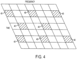
- One way to enable channel estimation in case of orthogonal frequency-division multiplexing (OFDM) transmission that is used in LTE systems, is to insert known reference symbols into the OFDM time-frequency grid, as shown for example in Figure 4 .
- downlink reference symbols 40 are inserted within predetermined OFDM symbols of each slot and with a frequency-domain spacing of, for example, six subcarriers (the downlink reference symbols are not shown to scale in Figure 4 ).
- the user terminal may perform interpolation/averaging over multiple reference symbols.
- the user terminal may not only use the reference symbols within that resource block but also, in the frequency domain, use neighbor resource blocks, as well as reference symbols of previously received slots/frames.
- the extent to which the user terminal can average over multiple resource blocks in the frequency and/or time domain depends on the channel characteristics. In case of high channel frequency selectivity, the possibility for averaging in the frequency domain is limited.
- the possibility of time-domain averaging that is the possibility to use reference symbols in previously received slots/subframes, is limited in case of fast channel variations, for example, due to high user terminal velocity.
- each transmit antenna of a transmitting unit there is one downlink reference signal transmitted from each antenna.
- the reference symbols of the second antenna are frequency multiplexed with the reference symbols of the first antenna, as shown for example in Figure 6a .
- the reference symbols for the third and fourth antennas are frequency multiplexed within the second OFDM symbol of each slot as shown in Figure 6b .
- the reference symbols for antennas three and four may only be transmitted within one OFDM symbol of each slot.
- a resource element carrying a reference symbol for a certain antenna carries no information about the other antennas.
- the time-domain reference-symbol density of the third and fourth antennas is reduced compared to the first and second antennas.
- This arrangement is used to limit the reference-signal overhead in case of four transmit antennas. At the same time, this arrangement has a negative impact on the possibility to track very fast channel variations.
- This arrangement in LTE systems is maintained because four-antenna spatial multiplexing is applied mainly to scenarios involving low mobility of the user terminal.
- the reason for retaining the higher reference-symbol density for the first and second antennas in case of four transmit antennas is that it is assumed in LTE systems that these reference signals will be used as part of the initial cell search during which the user terminal has not yet acquired full information about the number of transmit antennas within the cell.
- the configuration of the reference signals of the first and second antennas are the same regardless of the number of antennas.
- the reference signals and other information initially needed by the user terminal to connect and exchange data with the base station may be achieved via a primary broadcast channel (BCH).
- BCH primary broadcast channel
- the user terminal may decode the primary broadcast channel to obtain at least the minimum system information needed to decode the other channels, including a secondary broadcast channel and/or L1/L2 control channels.
- Both the synch channel and primary broadcast channel may be transmitted, in one exemplary embodiment, from the base station at regular intervals.
- the primary broadcast channel has a predetermined number of bits allocated for each frame and each bit may be used to communicate pre-established information about the system. However, it is expensive and difficult to allocate a bit of the primary broadcast channel to include information about the number of antennas used by the base station, information that is need as will be discussed next.
- the user terminal will need to support at least two different transmit diversity modes, for two and four antennas, respectively. To decode these modes, accurate channel estimates are needed.
- common reference symbols are used as training data for computing such estimates.
- the reference symbols are distributed on all transmit antennas of the base station to allow estimation of the channels of all the antennas. As discussed above, the reference symbols density is lower on transmit antenna three and four to keep the signaling overhead low. This fact reduces the performance of the user terminal at high speed scenarios.
- the existing techniques used for high speed scenarios employ transmission modes which utilize only two antennas at the base station, wasting the transmission capabilities of the remaining two antennas.
- FIG. 7 shows a generic structure of the user terminal 14 according to an exemplary embodiment.
- the user terminal 14 includes one or more antennas 70 connected to processor 72.
- the processor 72 is configured to analyze and process signals received via the antennas 70.
- the processor 72 is connected to a memory 74 via a bus 76.
- the user terminal 14 may also include a switching unit 78 configured to switch from a transmission mode to another transmission mode.
- Other units and/or elements are, for example, an input/output unit 80 that allows a user to input commands to the processor 72 or a communication port 82 that allows the user terminal 14 to receive data from another communication system.
- the synch channel may provide the user terminal, in addition to synchronization information, with information about whether the transmission of data on the primary broadcast channel relies on one or several antenna ports (or antennas).
- the LTE specifications consider that an antenna port is defined by the presence of an antenna-port-specific reference signal. Thus, if identical reference signals are transmitted from several physical antennas, these antennas cannot be resolved from a user terminal point-of-view and the antennas can be jointly seen as a single antenna port. However, if each antenna uses a reference signal not used by the remaining antennas, there is a one to one mapping between the physical antennas and the antenna ports. To simplify the description of the exemplary embodiments, the term "antenna" will be used in the following.
- the user terminal Prior to decoding the primary BCH, when the user terminal receives signals from the base station (e.g., the synch channel) and the user terminal detects that multiple antenna ports are used by the base station to communicate data over the primary broadcast channel, a distinction between two and four antenna ports is not made and thus, the user terminal is not aware of the exact number of antenna ports. In some embodiments, the user terminal cannot even distinguish between single and multiple antenna ports. Hence, if the base station uses a non-transparent multi-antenna transmission scheme for the primary broadcast channel, the user terminal has to blindly detect the transmission scheme for the communication channels.
- the base station e.g., the synch channel
- the blind decoding also provides information about the number of antenna ports at the base station, and the same number is also used for the other control channels.
- this is not the case in all the exemplary embodiments and thus, this simple mapping between the diversity mode and the number of transmit antennas fails for specific cases.
- the number of transmit modes (two) does not correspond to the number of antenna ports (four), i.e., the control channels are not necessarily transmitted with the same number of antennas as there are antenna ports in the system. Therefore, the number of antennas for the data channels may differ from the number of antennas used for the control channels. Under this scenario, there is however a need to signal to the user terminal the actual number of antenna ports.
- This signaling may be performed on the primary broadcast channel in order to make it possible to decode the remaining channels (control channels) by avoiding blind detection for these channels, which may be complex or even unreliable.
- the LTE specifications reference a secondary broadcast channel, which also contains system information.
- This channel may vary in size depending on the payload and information along this channel may be transmitted at a lower rate than the primary broadcast channel.
- This added flexibility of the secondary broadcast channel offers therefore, in one exemplary embodiment, the possibility to introduce in the secondary broadcast signal additional information bits rather than in the primary broadcast channel, in which each bit is already used and where the fixed number of bits means the primary broadcast channel needs to be designed to handle the worst case in terms of, for example, coverage.
- the secondary broadcast channel to signal to the user terminal, for example, the number of antenna ports used by the base station, the signaling overhead incurred by the primary broadcast channel may be maintained to a minimum.
- the signaling of the number of antenna ports is not performed via the primary broadcast channel but is deferred to one/some of the control channels decoded after decoding the primary broadcast channel.
- signaling the number of antenna ports on the primary broadcast channel is avoided while still being able to use either 2 Tx or 4 Tx transmission modes for common control and L1/L2 control channels.
- the common control and L1/L2 control channels may be decoded without the need of the blind detection of the transmit diversity mode used for these channels.
- the number of antenna ports used for transmitting the control channels in LTE e.g., secondary broadcast channel and physical downlink control channels (PDCCH)) decoded after decoding the primary broadcast channel is a known deterministic function of the number of antenna ports used for the primary broadcast channel. For example, it may be decided that the base station emits the primary broadcast channel using a first transmission mode and emits the control channels using a second transmission mode or vice versa or the base station uses the same transmission mode for both the primary broadcast channel and the control channels. Thus, by blindly detecting the transmission mode of the primary broadcast channel, the transmission mode for the control channels is known.
- LTE e.g., secondary broadcast channel and physical downlink control channels (PDCCH)
- the transmission mode used for the primary broadcast channel is blindly detected. Examples of blindly detecting the transmission mode for the primary broadcast channel include trying to decode the received signals assuming different transmission modes. For each assumed transmission mode, the cyclic redundancy check (CRC) for the primary broadcast channel is performed and when detected to be in a predetermined range, that assumed transmission mode is considered as the detected transmission mode.
- the user terminal uses the transmission mode of the primary broadcast channel to determine which transmission mode to assume for the later decoded common and L1/L2 control channels, thus facilitating decoding of these control channels. This mechanism works because the number of antennas used for the primary broadcast channel also determines how many antennas are used for transmitting the later decoded control channels.
- a process for determining the transmit mode of the base station is discussed with reference to Figure 8 . It is assumed in this embodiment that the common control and L1/L2 control channels may use either 2 Tx transmit diversity or 4 Tx transmit diversity.
- the user terminal is initially informed via the synch channel in step 80 that one or several antenna ports are used at least for the primary broadcast channel. Alternatively, the synch channel gives no information about the number of antennas and the present exemplary embodiment can be straightforwardly modified to encompass also this case. As discussed above, the synch channel does not inform the user terminal about the exact number of antenna ports when more than one antenna port is used by the base station.
- the user terminal receives in step 82 the primary broadcast channel and blindly detects which of the two transmit diversity schemes is used.
- the user terminal may perform the blind detection by decoding the primary broadcast channel under the assumption of both hypotheses (i.e., two antenna ports and four antenna ports) and determining which hypothesis gives the best CRC.
- the cyclic redundancy check is one approach to handle transmission errors as disclosed in Dahlman et al., 3G Evolution HSBA and LTE for Mobile Broadband, page 121, Elsevier, (2007 ), the entire content of which is incorporated here by reference.
- the user terminal knows that there are four antenna ports at the base station and the user terminal also knows that the same transmit diversity scheme is used for the L1/L2 control and/or the secondary broadcast channel.
- the user terminal then may start decoding these channels. Once these channels are decoded, the base station may transmit the exact number of antenna ports on these channels in step 86, instead of transmitting the same data on the primary broadcast channel.
- the explicitly signaled number of antenna ports may then be applicable to other channels (all or a subset of them), e.g. physical shared data channels such as PDSCH in LTE. Having the exact number of antenna ports used by the base station, the user terminal may start to receive data on the physical shared data channels in step 88.
- the physical shared data channels convey the user specific data on the logical data channels. But they may also be used to send the information corresponding to the secondary broadcast channel.
- the user terminal is not aware whether two or four antenna ports are present at the base station.
- the user terminal knows that the L1/L2 control and/or the secondary broadcast channel also uses the 2 Tx transmit diversity since the system is designed so that L1/L2 control and the secondary broadcast channel is using the same number of transmit antennas as the primary broadcast channel.
- the user terminal may decode in step 86 the L1/L2 control and/or the secondary broadcast channel without knowing the exact number of antenna ports configured in the cell.
- the number of antenna ports may then be signaled on one of these control channels, e.g., the secondary broadcast channel, in step 86 and the user terminal may start receiving data via the shared data channels in step 88, where these data channels are then using the number of transmit antennas signaled on the secondary broadcast channel.
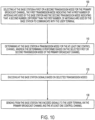
- the steps of a method, according to an exemplary embodiment, for selecting reception and decoding of a first and second transmission modes at a user terminal are shown in Figure 9 .
- the user terminal receives via plural channels communicated information from a base station having multiple antennas, the plural channels include a primary broadcast channel and at least one control channel.
- the user terminal receives data from the base station via the primary broadcast channel
- the user terminal detects from the received data whether a first or a second transmission mode is used by the base station, the first transmission mode indicating that a first number of antennas are used by the base station and the second transmission mode indicating that a second number, different from the first number, of antennas are used by the base station to communicate with the user terminal over at least one control channel.
- the user terminal uses the determined transmission mode of the primary broadcast channel for assisting in decoding the at least one control channel.
- a method for selecting at a base station transmission and coding of a transmission mode used by the base station to communicate information to a user terminal via plural channels the base station having multiple antennas and the plural channels including a primary broadcast channel and at least one control channel.
- the base station selects a first or a second transmission mode for the primary broadcast channel, the first transmission mode indicating that a first number of antennas are used by the base station and the second transmission mode indicating that a second number, different than the first number, of antennas are used by the base station to communicate with the user terminal.
- the base station determines a transmission mode for the at least one control channel, where the determining is performed based on the selected first or second transmission mode of the primary broadcast channel.
- the base station encodes signals based on selected transmission modes, and in step 130 the base station sends the encoded signals to the user terminal via the primary broadcast channel and the at least one control channel.
- one advantage of the discussed exemplary embodiments is avoiding signaling the number of antenna ports on the primary broadcast channel, allowing for fast processing based on the first and second antenna ports while still allowing transmit diversity modes (use of the full number of antenna ports available at the base station) for the common control and L1/L2 control channels. This may be beneficial in high speed scenarios where the reduced reference signal density for the third and fourth antenna ports would negatively impact the link quality of the control channels in case the four Tx transmit diversity mode is used.
- the number of transmit antennas used for the primary broadcast channel determine the number of transmit antennas used for the subsequent control channels and explicitly signal the number of transmit antennas on the secondary BCH or the other control channels, it becomes possible to use a different number of antennas for the shared data channels and the control channels.
- the disclosed exemplary embodiments provide a user terminal, a system, a method and a computer program product for selecting a transmission mode used by a base station when communicating with the user terminal. It should be understood that this description is not intended to limit the invention. On the contrary, the exemplary embodiments are intended to cover alternatives, modifications and equivalents, which are included in the spirit and scope of the invention as defined by the appended claims. Further, in the detailed description of the exemplary embodiments, numerous specific details are set forth in order to provide a comprehensive understanding of the claimed invention. However, one skilled in the art would understand that various embodiments may be practiced without such specific details.
- the exemplary embodiments may be embodied in a wireless communication device, a telecommunication network, as a method or in a computer program product. Accordingly, the exemplary embodiments may take the form of an entirely hardware embodiment or an embodiment combining hardware and software aspects. Further, the exemplary embodiments may take the form of a computer program product stored on a computer-readable storage medium having computer-readable instructions embodied in the medium. Any suitable computer readable medium may be utilized including hard disks, CD-ROMs, digital versatile disc (DVD), optical storage devices, or magnetic storage devices such a floppy disk or magnetic tape. Other non-limiting examples of computer readable media include flash-type memories or other known memories.
Landscapes
- Engineering & Computer Science (AREA)
- Computer Networks & Wireless Communication (AREA)
- Signal Processing (AREA)
- Mobile Radio Communication Systems (AREA)
Claims (22)
- Verfahren zum Auswählen von Empfang und Decodierung eines von einem eNodeB (10) verwendeten Übertragungsmodus an einem Benutzerendgerät (14), wobei das Benutzerendgerät (14) vom eNodeB (10) kommunizierte Informationen über mehrere Kanäle empfängt, der mehrere Antennen (12) aufweist, wobei die mehreren Kanäle einen primären Broadcastkanal und mindestens einen Steuerkanal umfassen, wobei das Verfahren umfasst:Empfangen von Initiierungsdaten vom eNodeB (10) am Benutzerendgerät (14) über den primären Broadcastkanal;Erkennen aus den empfangenen Initiierungsdaten, ob ein erster oder ein zweiter Übertragungsmodus vom eNodeB (10) für den primären Broadcastkanal verwendet wird, wobei der erste Übertragungsmodus angibt, dass eine erste Anzahl von Antennen vom eNodeB (10) verwendet wird, und der zweite Übertragungsmodus angibt, dass eine von der ersten Anzahl verschiedene zweite Anzahl von Antennen vom eNodeB (10) verwendet wird, um mit dem Benutzerendgerät (14) zu kommunizieren; undDecodieren des mindestens einen Steuerkanals unter Verwendung des erkannten Übertragungsmodus des primären Broadcastkanals,wobei der erkannte Übertragungsmodus des primären Broadcastkanals den Übertragungsmodus für den später decodierten mindestens einen Steuerkanal bestimmt.
- Verfahren nach Anspruch 1, ferner umfassend:
Empfangen der Anzahl von Antennen, die zur Übertragung über mindestens einen des einen oder der mehreren Steuerkanäle und nicht über den primären Broadcastkanal verwendet wird, nachdem der erste oder zweite Übertragungsmodus basierend auf dem primären Broadcastkanal erkannt wurde. - Verfahren nach Anspruch 1, wobei das Erkennen ferner umfasst:
Erkennen des ersten oder des zweiten Übertragungsmodus für den primären Broadcastkanal am Benutzerendgerät ohne Kenntnis der Anzahl von Antennen am eNodeB. - Verfahren nach Anspruch 1, wobei die Anzahl von Antennen eine, zwei oder vier Antennen umfasst.
- Verfahren nach Anspruch 1, wobei die mehreren Kanäle ferner einen sekundären Broadcastkanal und L1/L2-Steuerkanäle umfassen.
- Verfahren nach Anspruch 1, wobei der primäre Broadcastkanal kein Nachrichtenfeld aufweist, das zum Übertragen der vom eNodeB zum Kommunizieren mit dem Benutzerendgerät verwendeten Anzahl von Antennen verfügbar ist.
- Verfahren nach Anspruch 1, ferner umfassend:
Umschalten von einem des ersten und des zweiten Übertragungsmodus in einen anderen des ersten und des zweiten Übertragungsmodus beim Decodieren des primären Broadcastkanals und des mindestens einen Steuerkanals nach dem Übertragen der Anzahl von Antennen über den mindestens einen Steuerkanal an das Benutzerendgerät und nach einem voreingestellten Zeitintervall. - Verfahren nach Anspruch 1, wobei das Benutzerendgerät so konfiguriert ist, dass es einen Übertragungsmodus für den mindestens einen Steuerkanal verwendet, der eine voreingestellte Funktion des Übertragungsmodus des primären Broadcastkanals ist.
- Verfahren nach Anspruch 1, wobei das Erkennen als blindes Erkennen realisiert ist und/oder wobei das Decodieren ohne Blinderkennung des Übertragungsmodus erfolgt, der verwendet wird.
- Kommunikations-Benutzerendgerät (14), das so konfiguriert ist, dass es einen Empfang eines Übertragungsmodus von Daten auswählt, die von einem eNodeB (10) über mehrere Kanäle an das Benutzerendgerät (14) übertragen werden, wobei die mehreren Kanäle einen primären Broadcastkanal und mindestens einen Steuerkanal umfassen, wobei das Endgerät (14)so konfiguriert ist, dass es Initiierungsdaten vom eNodeB (10) über den primären Broadcastkanal empfängt; undso konfiguriert ist, dass es aus den empfangenen Initiierungsdaten erkennt, ob ein erster oder ein zweiter Übertragungsmodus vom eNodeB (10) für den primären Broadcastkanal verwendet wird, wobei der erste Übertragungsmodus angibt, dass eine erste Anzahl von Antennen vom eNodeB (10) verwendet wird, und der zweite Übertragungsmodus angibt, dass eine von der ersten Anzahl verschiedene zweite Anzahl von Antennen vom eNodeB (10) verwendet wird, um mit dem Benutzerendgerät (14) zu kommunizieren, und den mindestens einen Steuerkanal unter Verwendung des erkannten Übertragungsmodus des primären Broadcastkanals decodiert,wobei der erkannte Übertragungsmodus des primären Broadcastkanals den Übertragungsmodus für den später decodierten mindestens einen Steuerkanal bestimmt.
- Benutzerendgerät nach Anspruch 10, das zum Durchführen eines Verfahrens nach einem der Ansprüche 1 bis 9 ausgelegt ist.
- Kommunikationsnetzwerk (10, 14), umfassend:einen eNodeB (10), der so konfiguriert ist, dass er über mehrere Kanäle, die einen primären Broadcastkanal und mindestens einen Steuerkanal umfassen, Initiierungsdaten unter Verwendung eines ersten oder eines zweiten Übertragungsmodus überträgt, wobei der erste Übertragungsmodus angibt, dass eine erste Anzahl von Antennen vom eNodeB (10) verwendet wird, und der zweite Übertragungsmodus angibt, dass eine von der ersten Anzahl verschiedene zweite Anzahl von Antennen vom eNodeB (10) verwendet wird, um die Initiierungsdaten zu übertragen; undein Benutzerendgerät (14), dass so konfiguriert ist, dass es die Initiierungsdaten über den primären Broadcastkanal empfängt, aus den empfangenen Initiierungsdaten erkennt, ob der erste oder der zweite Übertragungsmodus vom eNodeB (10) für den primären Broadcastkanal verwendet wird, und den mindestens einen Steuerkanal unter Verwendung des erkannten Übertragungsmodus des primären Broadcastkanals decodiert, um den mindestens einen Steuerkanal zu decodieren,wobei der erkannte Übertragungsmodus des primären Broadcastkanals den Übertragungsmodus für den später decodierten mindestens einen Steuerkanal bestimmt.
- Verfahren zum Auswählen an einem eNodeB (10) von Übertragung und Codierung eines Übertragungsmodus, der vom eNodeB (10) zum Kommunizieren von Informationen über eine Mehrzahl von Kanälen an ein Benutzerendgerät (14) verwendet wird, wobei der eNodeB (10) mehrere Antennen (12) aufweist und die mehreren Kanäle einen primären Broadcastkanal und mindestens einen Steuerkanal umfassen, wobei das Verfahren umfasst:Auswählen eines ersten oder eines zweiten Übertragungsmodus für den primären Broadcastkanal am eNodeB (10), wobei der erste Übertragungsmodus angibt, dass eine erste Anzahl von Antennen vom eNodeB (10) verwendet wird, und der zweite Übertragungsmodus angibt, dass eine von der ersten Anzahl verschiedene zweite Anzahl von Antennen vom eNodeB (10) verwendet wird, um mit dem Benutzerendgerät (14) zu kommunizieren;Bestimmen eines Übertragungsmodus für den mindestens einen Steuerkanal am eNodeB (10), wobei das Bestimmen basierend auf dem ausgewählten Übertragungsmodus des primären Broadcastkanals erfolgt;Codieren von Signalen am eNodeB (10) basierend auf dem ausgewählten Übertragungsmodus und dem bestimmten Übertragungsmodus; undSenden der codierten Signale vom eNodeB (10) über den primären Broadcastkanal und den mindestens einen Steuerkanal an das Benutzerendgerät (14),wobei der ausgewählte Übertragungsmodus des primären Broadcastkanals den Übertragungsmodus für den mindestens einen Steuerkanal bestimmt.
- Verfahren nach Anspruch 13, wobei die vom eNodeB verwendete Anzahl von Antennen über einen vom primären Broadcastkanal verschiedenen Kanal an das Benutzerendgerät gesendet wird, nach dem der erste oder der zweite Übertragungsmodus vom Benutzerendgerät basierend auf dem primären Broadcastkanal erkannt wurde.
- Verfahren nach Anspruch 14, wobei der Kanal, über den die vom eNodeB verwendete Anzahl von Antennen gesendet wird, einer des einen oder der mehreren Steuerkanäle ist.
- Verfahren nach Anspruch 13, wobei die Anzahl von Antennen am eNodeB eine, zwei oder vier beträgt.
- Verfahren nach Anspruch 13, ferner umfassend:
Senden eines sekundären Broadcastkanals und von L1/L2-Steuerkanälen vom eNodeB. - Verfahren nach Anspruch 13, wobei der primäre Broadcastkanal kein Nachrichtenfeld aufweist, das zum Übertragen der vom eNodeB zum Kommunizieren mit dem Benutzerendgerät verwendeten Anzahl von Antennen verfügbar ist.
- Verfahren nach Anspruch 13, ferner umfassend:
Umschalten von einem des ersten und des zweiten Übertragungsmodus in einen anderen des ersten und des zweiten Übertragungsmodus beim Codieren des primären Broadcastkanals und des mindestens einen Steuerkanals nach dem Übertragen der Anzahl von Antennen am eNodeB über den mindestens einen Steuerkanal an das Benutzerendgerät und nach einem voreingestellten Zeitintervall. - Verfahren nach Anspruch 13, wobei das Bestimmen ferner umfasst:
Anwenden eines Übertragungsmodus für den mindestens einen Steuerkanal, wobei der angewendete Übertragungsmodus eine voreingestellte Funktion des ausgewählten Übertragungsmodus des primären Broadcastkanals ist. - eNodeB (10) zum Auswählen von Übertragung und Codierung eines Übertragungsmodus, der vom eNodeB (10) zum Kommunizieren von Informationen über eine Mehrzahl von Kanälen an ein Benutzerendgerät (14) verwendet wird, wobei der eNodeB (10) mehrere Antennen (12) aufweist und die mehreren Kanäle einen primären Broadcastkanal und mindestens einen Steuerkanal umfassen, wobei der eNodeB ausgelegt ist zum:Auswählen eines ersten oder eines zweiten Übertragungsmodus für den primären Broadcastkanal am eNodeB (10), wobei der erste Übertragungsmodus angibt, dass eine erste Anzahl von Antennen vom eNodeB (10) verwendet wird, und der zweite Übertragungsmodus angibt, dass eine von der ersten Anzahl verschiedene zweite Anzahl von Antennen vom eNodeB (10) verwendet wird, um mit dem Benutzerendgerät (14) zu kommunizieren;Bestimmen eines Übertragungsmodus für den mindestens einen Steuerkanal am eNodeB (10), wobei das Bestimmen basierend auf dem ausgewählten Übertragungsmodus des primären Broadcastkanals erfolgt;Codieren von Signalen am eNodeB (10) basierend auf dem ausgewählten Übertragungsmodus und dem bestimmten Übertragungsmodus; undSenden der codierten Signale vom eNodeB (10) über den primären Broadcastkanal und den mindestens einen Steuerkanal an das Benutzerendgerät (14),wobei der ausgewählte Übertragungsmodus des primären Broadcastkanals den Übertragungsmodus für den mindestens einen Steuerkanal bestimmt.
- eNodeB (10) nach Anspruch 21, der zum Durchführen eines Verfahrens nach einem der Ansprüche 13 bis 20 ausgelegt ist.
Applications Claiming Priority (3)
| Application Number | Priority Date | Filing Date | Title |
|---|---|---|---|
| SE0701119 | 2007-05-08 | ||
| EP08767119.4A EP2153565B1 (de) | 2007-05-08 | 2008-05-05 | Übertragungsmodusauswahl |
| PCT/SE2008/050507 WO2008136750A2 (en) | 2007-05-08 | 2008-05-05 | Method for detecting transmission mode in a system using multiple antennas |
Related Parent Applications (1)
| Application Number | Title | Priority Date | Filing Date |
|---|---|---|---|
| EP08767119.4A Division EP2153565B1 (de) | 2007-05-08 | 2008-05-05 | Übertragungsmodusauswahl |
Publications (3)
| Publication Number | Publication Date |
|---|---|
| EP3624372A1 EP3624372A1 (de) | 2020-03-18 |
| EP3624372C0 EP3624372C0 (de) | 2024-10-09 |
| EP3624372B1 true EP3624372B1 (de) | 2024-10-09 |
Family
ID=39944134
Family Applications (2)
| Application Number | Title | Priority Date | Filing Date |
|---|---|---|---|
| EP19192212.9A Active EP3624372B1 (de) | 2007-05-08 | 2008-05-05 | Übertragungsmodusauswahl |
| EP08767119.4A Active EP2153565B1 (de) | 2007-05-08 | 2008-05-05 | Übertragungsmodusauswahl |
Family Applications After (1)
| Application Number | Title | Priority Date | Filing Date |
|---|---|---|---|
| EP08767119.4A Active EP2153565B1 (de) | 2007-05-08 | 2008-05-05 | Übertragungsmodusauswahl |
Country Status (8)
| Country | Link |
|---|---|
| US (1) | US8331476B2 (de) |
| EP (2) | EP3624372B1 (de) |
| JP (1) | JP5238020B2 (de) |
| DK (1) | DK2153565T3 (de) |
| ES (2) | ES2757586T3 (de) |
| PL (1) | PL2153565T3 (de) |
| PT (1) | PT2153565T (de) |
| WO (1) | WO2008136750A2 (de) |
Families Citing this family (16)
| Publication number | Priority date | Publication date | Assignee | Title |
|---|---|---|---|---|
| US8290088B2 (en) | 2007-08-07 | 2012-10-16 | Research In Motion Limited | Detecting the number of transmit antennas in a base station |
| US8676133B2 (en) * | 2008-09-19 | 2014-03-18 | Qualcomm Incorporated | Reference signal design for LTE A |
| WO2010072020A1 (en) * | 2008-12-22 | 2010-07-01 | Huawei Technologies Co., Ltd. | Method for signalling in a wireless communication system |
| BRPI0924212B1 (pt) | 2009-01-13 | 2018-06-26 | Huawei Technologies Co., Ltd. | Método e dispositivo para enviar e adquirir informação |
| US8982759B2 (en) * | 2009-01-15 | 2015-03-17 | Lg Electronics Inc. | System information transmitting and receiving device |
| WO2010137866A2 (ko) * | 2009-05-26 | 2010-12-02 | 엘지전자 주식회사 | 무선 통신 시스템에서 안테나 정보를 획득하는 방법 및 장치 |
| CA2766648C (en) * | 2009-06-24 | 2015-01-27 | Research In Motion Limited | Methods and apparatus to perform antenna management |
| US9031008B2 (en) | 2009-10-30 | 2015-05-12 | Samsung Electronics Co., Ltd. | Methods and apparatus for multi-user MIMO transmissions in wireless communication systems |
| US20120218945A1 (en) * | 2009-11-25 | 2012-08-30 | Telefonaktiebolaget Lm Ericsson (Publ) | Method and Arrangement for Random Access Diversity |
| KR101461974B1 (ko) * | 2010-02-02 | 2014-11-14 | 엘지전자 주식회사 | 확장 캐리어에서의 측정 수행 방법 및 장치 |
| CN102859953B (zh) * | 2010-04-30 | 2016-08-03 | 瑞典爱立信有限公司 | 用于下行链路控制信令的方法、接收器和传送器 |
| KR102040614B1 (ko) * | 2011-05-10 | 2019-11-05 | 엘지전자 주식회사 | 복수의 안테나 포트를 이용하여 신호를 전송하는 방법 및 이를 위한 송신단 장치 |
| US9755781B2 (en) | 2012-11-28 | 2017-09-05 | Sony Corporation | Broadcast system and method for error correction using redundant data |
| WO2014082997A1 (en) * | 2012-11-28 | 2014-06-05 | Sony Corporation | Receiver for receiving data in a broadcast system |
| EP2926488A1 (de) * | 2012-11-28 | 2015-10-07 | Sony Corporation | Empfänger zum empfangen von daten in einem rundfunksystem mit redundanzdaten |
| CN113824482B (zh) * | 2020-06-19 | 2023-09-19 | 成都鼎桥通信技术有限公司 | 天线切换方法、设备及移动终端 |
Family Cites Families (11)
| Publication number | Priority date | Publication date | Assignee | Title |
|---|---|---|---|---|
| JP2002077114A (ja) * | 2000-08-24 | 2002-03-15 | Hitachi Kokusai Electric Inc | ダイバーシチ受信機 |
| US8320301B2 (en) * | 2002-10-25 | 2012-11-27 | Qualcomm Incorporated | MIMO WLAN system |
| US8149810B1 (en) * | 2003-02-14 | 2012-04-03 | Marvell International Ltd. | Data rate adaptation in multiple-in-multiple-out systems |
| US7099678B2 (en) * | 2003-04-10 | 2006-08-29 | Ipr Licensing, Inc. | System and method for transmit weight computation for vector beamforming radio communication |
| JP4130191B2 (ja) * | 2004-01-28 | 2008-08-06 | 三洋電機株式会社 | 送信装置 |
| JP4130210B2 (ja) * | 2004-01-28 | 2008-08-06 | 三洋電機株式会社 | 送信装置および受信装置 |
| WO2005099103A1 (ja) * | 2004-04-05 | 2005-10-20 | Matsushita Electric Industrial Co., Ltd. | 無線通信装置および無線通信方法 |
| JP4091578B2 (ja) * | 2004-08-11 | 2008-05-28 | 株式会社東芝 | 無線通信装置及びアンテナ数の推定方法 |
| JP2006135674A (ja) * | 2004-11-05 | 2006-05-25 | Ntt Docomo Inc | 移動通信用受信装置、移動通信用送信装置、移動通信用受信方法、および、移動通信用送信方法 |
| JP5006001B2 (ja) * | 2006-08-22 | 2012-08-22 | 株式会社エヌ・ティ・ティ・ドコモ | 下りリンクmimo伝送制御方法および基地局装置 |
| US8135359B2 (en) * | 2008-01-04 | 2012-03-13 | Nokia Corporation | Method and apparatus for conveying antenna configuration information |
-
2008
- 2008-05-05 US US12/530,982 patent/US8331476B2/en active Active
- 2008-05-05 ES ES08767119T patent/ES2757586T3/es active Active
- 2008-05-05 EP EP19192212.9A patent/EP3624372B1/de active Active
- 2008-05-05 PL PL08767119T patent/PL2153565T3/pl unknown
- 2008-05-05 WO PCT/SE2008/050507 patent/WO2008136750A2/en not_active Ceased
- 2008-05-05 EP EP08767119.4A patent/EP2153565B1/de active Active
- 2008-05-05 JP JP2010507362A patent/JP5238020B2/ja active Active
- 2008-05-05 ES ES19192212T patent/ES2989201T3/es active Active
- 2008-05-05 DK DK08767119T patent/DK2153565T3/da active
- 2008-05-05 PT PT87671194T patent/PT2153565T/pt unknown
Non-Patent Citations (1)
| Title |
|---|
| GOSTA LEIJONHUFVUD: "THE NEED FOR ATM OVER FRACTIONAL PHYSICAL LINKS IN MOBILE RADIO ACCESS NETWORKS", ITU-T DRAFT ; STUDY PERIOD 1997-2000, INTERNATIONAL TELECOMMUNICATION UNION, GENEVA ; CH, vol. 11/13, 12/13, 15 February 1999 (1999-02-15), pages 1 - 3, XP017473369 * |
Also Published As
| Publication number | Publication date |
|---|---|
| EP3624372C0 (de) | 2024-10-09 |
| EP2153565A2 (de) | 2010-02-17 |
| DK2153565T3 (da) | 2019-11-18 |
| JP5238020B2 (ja) | 2013-07-17 |
| US20100046651A1 (en) | 2010-02-25 |
| US8331476B2 (en) | 2012-12-11 |
| ES2989201T3 (es) | 2024-11-25 |
| WO2008136750A2 (en) | 2008-11-13 |
| EP3624372A1 (de) | 2020-03-18 |
| ES2757586T3 (es) | 2020-04-29 |
| PT2153565T (pt) | 2019-10-10 |
| WO2008136750A3 (en) | 2008-12-31 |
| JP2010526512A (ja) | 2010-07-29 |
| EP2153565A4 (de) | 2015-03-18 |
| PL2153565T3 (pl) | 2020-02-28 |
| EP2153565B1 (de) | 2019-08-21 |
Similar Documents
| Publication | Publication Date | Title |
|---|---|---|
| EP2153565B1 (de) | Übertragungsmodusauswahl | |
| KR101842687B1 (ko) | Lte-a에서의 시간 트래킹을 위한 개선된 기준 신호 설계 | |
| CN105122701B (zh) | 控制无线通信系统中的干扰的方法和装置 | |
| US9258104B2 (en) | Pattern indicator signal for new DMRS pattern | |
| KR101277596B1 (ko) | 무선 통신을 위한 공간 간섭 완화 방식들 | |
| CN103503539B (zh) | 基站、终端、通信系统、通信方法以及集成电路 | |
| CN104380648B (zh) | 基于信道状态信息可靠性的自适应预编码 | |
| JP5763031B2 (ja) | 無線通信システムにおける多重アンテナ構成の信号伝達 | |
| US11102798B2 (en) | Method and device in UE and base station used for wireless communication | |
| US11757566B2 (en) | Method and device in UE and base station for multi-antenna communication | |
| EP2139186B1 (de) | Bestimmung der Reihenfolge der Decodierung der Signale für sequentielle Interferenzunterdrückung | |
| JP2014511602A (ja) | 分散された遠隔ラジオ・ヘッドを用いた無線ネットワークにおいて、移動およびcsiフィードバックに基づいて、基準信号のためのアンテナ・ポートを選択すること | |
| KR20150107490A (ko) | 무선통신 시스템에서 간섭 신호 제거 및 억제를 위한 제어정보 전송 방법 및 장치 | |
| US12244385B2 (en) | Method and device in UE and base station for multi-antenna transmission | |
| EP2544420A1 (de) | Verfahren zur Übertragung von Daten in einem Kommunikationssystem, erster Netzwerkknoten und zweiter Netzwerkknoten dafür | |
| WO2021233294A1 (en) | Method and device in ue and base station for wireless communication | |
| KR20210018951A (ko) | 채널 추정 방법 및 장치, 및 통신 시스템 | |
| WO2014165656A1 (en) | Pattern indicator signal for new dmrs pattern | |
| TW201304448A (zh) | 通訊系統中傳輸資料之方法及其第一網路節點及第二網路節點 | |
| CN117880855B (zh) | 一种通信系统、方法及相关设备 | |
| KR102238665B1 (ko) | 무선 통신 시스템에서 제어 정보 송수신 방법 및 장치 |
Legal Events
| Date | Code | Title | Description |
|---|---|---|---|
| PUAI | Public reference made under article 153(3) epc to a published international application that has entered the european phase |
Free format text: ORIGINAL CODE: 0009012 |
|
| STAA | Information on the status of an ep patent application or granted ep patent |
Free format text: STATUS: THE APPLICATION HAS BEEN PUBLISHED |
|
| AC | Divisional application: reference to earlier application |
Ref document number: 2153565 Country of ref document: EP Kind code of ref document: P |
|
| AK | Designated contracting states |
Kind code of ref document: A1 Designated state(s): AT BE BG CH CY CZ DE DK EE ES FI FR GB GR HR HU IE IS IT LI LT LU LV MC MT NL NO PL PT RO SE SI SK TR |
|
| STAA | Information on the status of an ep patent application or granted ep patent |
Free format text: STATUS: REQUEST FOR EXAMINATION WAS MADE |
|
| 17P | Request for examination filed |
Effective date: 20200918 |
|
| RBV | Designated contracting states (corrected) |
Designated state(s): AT BE BG CH CY CZ DE DK EE ES FI FR GB GR HR HU IE IS IT LI LT LU LV MC MT NL NO PL PT RO SE SI SK TR |
|
| STAA | Information on the status of an ep patent application or granted ep patent |
Free format text: STATUS: EXAMINATION IS IN PROGRESS |
|
| 17Q | First examination report despatched |
Effective date: 20211119 |
|
| GRAP | Despatch of communication of intention to grant a patent |
Free format text: ORIGINAL CODE: EPIDOSNIGR1 |
|
| STAA | Information on the status of an ep patent application or granted ep patent |
Free format text: STATUS: GRANT OF PATENT IS INTENDED |
|
| INTG | Intention to grant announced |
Effective date: 20240430 |
|
| GRAS | Grant fee paid |
Free format text: ORIGINAL CODE: EPIDOSNIGR3 |
|
| GRAA | (expected) grant |
Free format text: ORIGINAL CODE: 0009210 |
|
| STAA | Information on the status of an ep patent application or granted ep patent |
Free format text: STATUS: THE PATENT HAS BEEN GRANTED |
|
| AC | Divisional application: reference to earlier application |
Ref document number: 2153565 Country of ref document: EP Kind code of ref document: P |
|
| AK | Designated contracting states |
Kind code of ref document: B1 Designated state(s): AT BE BG CH CY CZ DE DK EE ES FI FR GB GR HR HU IE IS IT LI LT LU LV MC MT NL NO PL PT RO SE SI SK TR |
|
| REG | Reference to a national code |
Ref country code: CH Ref legal event code: EP |
|
| REG | Reference to a national code |
Ref country code: DE Ref legal event code: R096 Ref document number: 602008065111 Country of ref document: DE |
|
| REG | Reference to a national code |
Ref country code: IE Ref legal event code: FG4D |
|
| REG | Reference to a national code |
Ref country code: ES Ref legal event code: FG2A Ref document number: 2989201 Country of ref document: ES Kind code of ref document: T3 Effective date: 20241125 |
|
| U01 | Request for unitary effect filed |
Effective date: 20241018 |
|
| U07 | Unitary effect registered |
Designated state(s): AT BE BG DE DK EE FI FR IT LT LU LV MT NL PT RO SE SI Effective date: 20241107 |
|
| PG25 | Lapsed in a contracting state [announced via postgrant information from national office to epo] |
Ref country code: HR Free format text: LAPSE BECAUSE OF FAILURE TO SUBMIT A TRANSLATION OF THE DESCRIPTION OR TO PAY THE FEE WITHIN THE PRESCRIBED TIME-LIMIT Effective date: 20241009 Ref country code: IS Free format text: LAPSE BECAUSE OF FAILURE TO SUBMIT A TRANSLATION OF THE DESCRIPTION OR TO PAY THE FEE WITHIN THE PRESCRIBED TIME-LIMIT Effective date: 20250209 |
|
| PG25 | Lapsed in a contracting state [announced via postgrant information from national office to epo] |
Ref country code: NO Free format text: LAPSE BECAUSE OF FAILURE TO SUBMIT A TRANSLATION OF THE DESCRIPTION OR TO PAY THE FEE WITHIN THE PRESCRIBED TIME-LIMIT Effective date: 20250109 |
|
| PG25 | Lapsed in a contracting state [announced via postgrant information from national office to epo] |
Ref country code: GR Free format text: LAPSE BECAUSE OF FAILURE TO SUBMIT A TRANSLATION OF THE DESCRIPTION OR TO PAY THE FEE WITHIN THE PRESCRIBED TIME-LIMIT Effective date: 20250110 |
|
| PG25 | Lapsed in a contracting state [announced via postgrant information from national office to epo] |
Ref country code: PL Free format text: LAPSE BECAUSE OF FAILURE TO SUBMIT A TRANSLATION OF THE DESCRIPTION OR TO PAY THE FEE WITHIN THE PRESCRIBED TIME-LIMIT Effective date: 20241009 |
|
| U20 | Renewal fee for the european patent with unitary effect paid |
Year of fee payment: 18 Effective date: 20250527 |
|
| PGFP | Annual fee paid to national office [announced via postgrant information from national office to epo] |
Ref country code: ES Payment date: 20250602 Year of fee payment: 18 Ref country code: GB Payment date: 20250527 Year of fee payment: 18 |
|
| PG25 | Lapsed in a contracting state [announced via postgrant information from national office to epo] |
Ref country code: SK Free format text: LAPSE BECAUSE OF FAILURE TO SUBMIT A TRANSLATION OF THE DESCRIPTION OR TO PAY THE FEE WITHIN THE PRESCRIBED TIME-LIMIT Effective date: 20241009 |
|
| PG25 | Lapsed in a contracting state [announced via postgrant information from national office to epo] |
Ref country code: CZ Free format text: LAPSE BECAUSE OF FAILURE TO SUBMIT A TRANSLATION OF THE DESCRIPTION OR TO PAY THE FEE WITHIN THE PRESCRIBED TIME-LIMIT Effective date: 20241009 |
|
| PLBE | No opposition filed within time limit |
Free format text: ORIGINAL CODE: 0009261 |
|
| STAA | Information on the status of an ep patent application or granted ep patent |
Free format text: STATUS: NO OPPOSITION FILED WITHIN TIME LIMIT |
|
| 26N | No opposition filed |
Effective date: 20250710 |
|
| REG | Reference to a national code |
Ref country code: CH Ref legal event code: H13 Free format text: ST27 STATUS EVENT CODE: U-0-0-H10-H13 (AS PROVIDED BY THE NATIONAL OFFICE) Effective date: 20251223 |
|
| PG25 | Lapsed in a contracting state [announced via postgrant information from national office to epo] |
Ref country code: CH Free format text: LAPSE BECAUSE OF NON-PAYMENT OF DUE FEES Effective date: 20250531 |
|
| PG25 | Lapsed in a contracting state [announced via postgrant information from national office to epo] |
Ref country code: MC Free format text: LAPSE BECAUSE OF FAILURE TO SUBMIT A TRANSLATION OF THE DESCRIPTION OR TO PAY THE FEE WITHIN THE PRESCRIBED TIME-LIMIT Effective date: 20241009 |
|
| PG25 | Lapsed in a contracting state [announced via postgrant information from national office to epo] |
Ref country code: IE Free format text: LAPSE BECAUSE OF NON-PAYMENT OF DUE FEES Effective date: 20250505 |