EP3624461A1 - Procédé de détection d'anomalie, dispositif de surveillance, et dispositif de réseau - Google Patents
Procédé de détection d'anomalie, dispositif de surveillance, et dispositif de réseau Download PDFInfo
- Publication number
- EP3624461A1 EP3624461A1 EP18809706.7A EP18809706A EP3624461A1 EP 3624461 A1 EP3624461 A1 EP 3624461A1 EP 18809706 A EP18809706 A EP 18809706A EP 3624461 A1 EP3624461 A1 EP 3624461A1
- Authority
- EP
- European Patent Office
- Prior art keywords
- source
- monitoring
- packet loss
- window
- packets
- Prior art date
- Legal status (The legal status is an assumption and is not a legal conclusion. Google has not performed a legal analysis and makes no representation as to the accuracy of the status listed.)
- Granted
Links
Images






Classifications
-
- H—ELECTRICITY
- H04—ELECTRIC COMMUNICATION TECHNIQUE
- H04N—PICTORIAL COMMUNICATION, e.g. TELEVISION
- H04N21/00—Selective content distribution, e.g. interactive television or video on demand [VOD]
- H04N21/20—Servers specifically adapted for the distribution of content, e.g. VOD servers; Operations thereof
- H04N21/23—Processing of content or additional data; Elementary server operations; Server middleware
- H04N21/24—Monitoring of processes or resources, e.g. monitoring of server load, available bandwidth, upstream requests
- H04N21/2402—Monitoring of the downstream path of the transmission network, e.g. bandwidth available
-
- H—ELECTRICITY
- H04—ELECTRIC COMMUNICATION TECHNIQUE
- H04N—PICTORIAL COMMUNICATION, e.g. TELEVISION
- H04N21/00—Selective content distribution, e.g. interactive television or video on demand [VOD]
- H04N21/60—Network structure or processes for video distribution between server and client or between remote clients; Control signalling between clients, server and network components; Transmission of management data between server and client, e.g. sending from server to client commands for recording incoming content stream; Communication details between server and client
- H04N21/63—Control signaling related to video distribution between client, server and network components; Network processes for video distribution between server and clients or between remote clients, e.g. transmitting basic layer and enhancement layers over different transmission paths, setting up a peer-to-peer communication via Internet between remote STB's; Communication protocols; Addressing
- H04N21/647—Control signaling between network components and server or clients; Network processes for video distribution between server and clients, e.g. controlling the quality of the video stream, by dropping packets, protecting content from unauthorised alteration within the network, monitoring of network load, bridging between two different networks, e.g. between IP and wireless
- H04N21/64723—Monitoring of network processes or resources, e.g. monitoring of network load
- H04N21/6473—Monitoring network processes errors
-
- H—ELECTRICITY
- H04—ELECTRIC COMMUNICATION TECHNIQUE
- H04N—PICTORIAL COMMUNICATION, e.g. TELEVISION
- H04N21/00—Selective content distribution, e.g. interactive television or video on demand [VOD]
- H04N21/40—Client devices specifically adapted for the reception of or interaction with content, e.g. set-top-box [STB]; Operations thereof
- H04N21/43—Processing of content or additional data, e.g. demultiplexing additional data from a digital video stream; Elementary client operations, e.g. monitoring of home network or synchronising decoder's clock; Client middleware
- H04N21/442—Monitoring of processes or resources, e.g. detecting the failure of a recording device, monitoring the downstream bandwidth, the number of times a movie has been viewed, the storage space available from the internal hard disk
- H04N21/44209—Monitoring of downstream path of the transmission network originating from a server, e.g. bandwidth variations of a wireless network
-
- H—ELECTRICITY
- H04—ELECTRIC COMMUNICATION TECHNIQUE
- H04L—TRANSMISSION OF DIGITAL INFORMATION, e.g. TELEGRAPHIC COMMUNICATION
- H04L1/00—Arrangements for detecting or preventing errors in the information received
- H04L1/004—Arrangements for detecting or preventing errors in the information received by using forward error control
- H04L1/0045—Arrangements at the receiver end
-
- H—ELECTRICITY
- H04—ELECTRIC COMMUNICATION TECHNIQUE
- H04L—TRANSMISSION OF DIGITAL INFORMATION, e.g. TELEGRAPHIC COMMUNICATION
- H04L1/00—Arrangements for detecting or preventing errors in the information received
- H04L1/08—Arrangements for detecting or preventing errors in the information received by repeating transmission, e.g. Verdan system
-
- H—ELECTRICITY
- H04—ELECTRIC COMMUNICATION TECHNIQUE
- H04L—TRANSMISSION OF DIGITAL INFORMATION, e.g. TELEGRAPHIC COMMUNICATION
- H04L43/00—Arrangements for monitoring or testing data switching networks
- H04L43/08—Monitoring or testing based on specific metrics, e.g. QoS, energy consumption or environmental parameters
- H04L43/0823—Errors, e.g. transmission errors
- H04L43/0829—Packet loss
-
- H—ELECTRICITY
- H04—ELECTRIC COMMUNICATION TECHNIQUE
- H04N—PICTORIAL COMMUNICATION, e.g. TELEVISION
- H04N21/00—Selective content distribution, e.g. interactive television or video on demand [VOD]
- H04N21/20—Servers specifically adapted for the distribution of content, e.g. VOD servers; Operations thereof
- H04N21/23—Processing of content or additional data; Elementary server operations; Server middleware
- H04N21/24—Monitoring of processes or resources, e.g. monitoring of server load, available bandwidth, upstream requests
-
- H—ELECTRICITY
- H04—ELECTRIC COMMUNICATION TECHNIQUE
- H04N—PICTORIAL COMMUNICATION, e.g. TELEVISION
- H04N21/00—Selective content distribution, e.g. interactive television or video on demand [VOD]
- H04N21/40—Client devices specifically adapted for the reception of or interaction with content, e.g. set-top-box [STB]; Operations thereof
- H04N21/43—Processing of content or additional data, e.g. demultiplexing additional data from a digital video stream; Elementary client operations, e.g. monitoring of home network or synchronising decoder's clock; Client middleware
- H04N21/44—Processing of video elementary streams, e.g. splicing a video clip retrieved from local storage with an incoming video stream or rendering scenes according to encoded video stream scene graphs
-
- H—ELECTRICITY
- H04—ELECTRIC COMMUNICATION TECHNIQUE
- H04N—PICTORIAL COMMUNICATION, e.g. TELEVISION
- H04N21/00—Selective content distribution, e.g. interactive television or video on demand [VOD]
- H04N21/40—Client devices specifically adapted for the reception of or interaction with content, e.g. set-top-box [STB]; Operations thereof
- H04N21/43—Processing of content or additional data, e.g. demultiplexing additional data from a digital video stream; Elementary client operations, e.g. monitoring of home network or synchronising decoder's clock; Client middleware
- H04N21/442—Monitoring of processes or resources, e.g. detecting the failure of a recording device, monitoring the downstream bandwidth, the number of times a movie has been viewed, the storage space available from the internal hard disk
-
- H—ELECTRICITY
- H04—ELECTRIC COMMUNICATION TECHNIQUE
- H04N—PICTORIAL COMMUNICATION, e.g. TELEVISION
- H04N21/00—Selective content distribution, e.g. interactive television or video on demand [VOD]
- H04N21/60—Network structure or processes for video distribution between server and client or between remote clients; Control signalling between clients, server and network components; Transmission of management data between server and client, e.g. sending from server to client commands for recording incoming content stream; Communication details between server and client
- H04N21/63—Control signaling related to video distribution between client, server and network components; Network processes for video distribution between server and clients or between remote clients, e.g. transmitting basic layer and enhancement layers over different transmission paths, setting up a peer-to-peer communication via Internet between remote STB's; Communication protocols; Addressing
- H04N21/637—Control signals issued by the client directed to the server or network components
- H04N21/6375—Control signals issued by the client directed to the server or network components for requesting retransmission, e.g. of data packets lost or corrupted during transmission from server
-
- H—ELECTRICITY
- H04—ELECTRIC COMMUNICATION TECHNIQUE
- H04N—PICTORIAL COMMUNICATION, e.g. TELEVISION
- H04N21/00—Selective content distribution, e.g. interactive television or video on demand [VOD]
- H04N21/60—Network structure or processes for video distribution between server and client or between remote clients; Control signalling between clients, server and network components; Transmission of management data between server and client, e.g. sending from server to client commands for recording incoming content stream; Communication details between server and client
- H04N21/63—Control signaling related to video distribution between client, server and network components; Network processes for video distribution between server and clients or between remote clients, e.g. transmitting basic layer and enhancement layers over different transmission paths, setting up a peer-to-peer communication via Internet between remote STB's; Communication protocols; Addressing
- H04N21/643—Communication protocols
- H04N21/64322—IP
-
- H—ELECTRICITY
- H04—ELECTRIC COMMUNICATION TECHNIQUE
- H04N—PICTORIAL COMMUNICATION, e.g. TELEVISION
- H04N21/00—Selective content distribution, e.g. interactive television or video on demand [VOD]
- H04N21/60—Network structure or processes for video distribution between server and client or between remote clients; Control signalling between clients, server and network components; Transmission of management data between server and client, e.g. sending from server to client commands for recording incoming content stream; Communication details between server and client
- H04N21/63—Control signaling related to video distribution between client, server and network components; Network processes for video distribution between server and clients or between remote clients, e.g. transmitting basic layer and enhancement layers over different transmission paths, setting up a peer-to-peer communication via Internet between remote STB's; Communication protocols; Addressing
- H04N21/647—Control signaling between network components and server or clients; Network processes for video distribution between server and clients, e.g. controlling the quality of the video stream, by dropping packets, protecting content from unauthorised alteration within the network, monitoring of network load, bridging between two different networks, e.g. between IP and wireless
-
- H—ELECTRICITY
- H04—ELECTRIC COMMUNICATION TECHNIQUE
- H04N—PICTORIAL COMMUNICATION, e.g. TELEVISION
- H04N21/00—Selective content distribution, e.g. interactive television or video on demand [VOD]
- H04N21/60—Network structure or processes for video distribution between server and client or between remote clients; Control signalling between clients, server and network components; Transmission of management data between server and client, e.g. sending from server to client commands for recording incoming content stream; Communication details between server and client
- H04N21/63—Control signaling related to video distribution between client, server and network components; Network processes for video distribution between server and clients or between remote clients, e.g. transmitting basic layer and enhancement layers over different transmission paths, setting up a peer-to-peer communication via Internet between remote STB's; Communication protocols; Addressing
- H04N21/647—Control signaling between network components and server or clients; Network processes for video distribution between server and clients, e.g. controlling the quality of the video stream, by dropping packets, protecting content from unauthorised alteration within the network, monitoring of network load, bridging between two different networks, e.g. between IP and wireless
- H04N21/64723—Monitoring of network processes or resources, e.g. monitoring of network load
Definitions
- Embodiments of the present invention relate to the field of multimedia technologies, and in particular, to a fault detection method, a monitoring device, and a network device.
- IPTV Internet Protocol television, IPTV
- a video head end delivers a video stream; a network device transmits the video stream to a set top box (set top box, STB) deployed on a user side; and the STB transmits the video stream to a display device for displaying.
- a packet loss and a delay that occur in a network transmission process have different impact on the video service.
- a packet loss rate may be used to represent impact of network transmission quality on video quality.
- network transmission quality is monitored by using the packet loss rate. When a video service fault occurs (for example, erratic display occurs during playback), once it is determined that the packet loss rate is higher than a threshold, it indicates that a network transmission status is poor, and the video service fault is caused by network transmission.
- a network operator usually uses various packet loss recovery methods, for example, technologies such as forward error correction (Forward error correction, FEC) and retransmission (Re-Transmission, RET), to enhance a fault tolerance capability of the IPTV system for a network packet loss.
- FEC forward error correction
- RET retransmission
- Using a packet loss recovery method may affect sensitivity of the user side to the packet loss rate. In a scenario using the packet loss recovery method, if the packet loss rate is still used for fault detection, a detection result is inaccurate.
- This application provides a video quality monitoring method, a monitoring device, and a network device to accurately perform fault detection on a video service.
- a fault detection method includes: obtaining a video quality parameter of a monitored video stream, where in a specific implementation, the video quality parameter is determined according to a packet loss recovery method of the monitored video stream, the video quality parameter may include an effective packet loss factor, and the effective packet loss factor is used to indicate effectiveness of network packet loss recovery performed by using the packet loss recovery method of the monitored video stream; and finally, performing fault detection based on the video quality parameter of the monitored video stream.
- the video quality parameter that needs to be monitored is determined according to the packet loss recovery method of the monitored video stream.
- the parameter may include the effective packet loss factor, and the effective packet loss factor can indicate effectiveness of network packet loss recovery performed by using the packet loss recovery method. Because compensation of the packet loss recovery method for a packet loss in network transmission is considered, fault detection can be accurately performed on a video service based on the video quality parameter of the monitored video stream. For example, although a network status is poor, and a packet loss rate is relatively high, the effective packet loss factor is relatively low, that is, a lost source packet is recovered effectively by using the packet loss recovery method.
- a video service fault that occurs in this case is not caused by a network, but may be caused by a fault of a head end device or a fault of a user terminal.
- the method provided by this embodiment of the present invention improves accuracy of fault detection on the video service.
- the method before the obtaining a video quality parameter of a monitored video stream, the method further includes: sending a video quality parameter request message to at least one network device that the monitored video stream flows through, where the video quality parameter request message is used to indicate an identifier of the monitored video stream and the packet loss recovery method of the monitored video stream; for example, if the monitored video stream is a live video stream, the identifier of the monitored video stream may be a channel number or a multicast address and a port; or if the monitored video stream is an on-demand video stream, the identifier of the monitored video stream may be a quintuple; and the obtaining a video quality parameter of a monitored video stream specifically includes: obtaining the video quality parameter of the monitored video stream from the at least one network device.
- a monitoring device can obtain the video quality parameter that is of the monitored video stream and is reported by the at least one network device that the monitored video stream flows through.
- the effective packet loss factor may indicate effectiveness of network packet loss recovery performed by using the packet loss recovery method of the monitored video stream, for example, effectiveness of network packet loss recovery performed by using the packet loss recovery method of the monitored video stream, or a probability of effectively performing network packet loss recovery by using the packet loss recovery method of the monitored video stream.
- the video quality parameter includes the following parameter: a packet loss rate; if the packet loss recovery method of the monitored video stream is FEC, the video quality parameter includes the following parameters: a packet loss rate and a first effective packet loss factor (that is, the foregoing effective packet loss factor in the first aspect), where the first effective packet loss factor is used to indicate effectiveness of network packet loss recovery performed by using FEC; if both RET and FEC are set for the monitored video stream, the video quality parameter includes the following parameters: a packet loss rate, a maximum consecutive packet loss quantity, and a second effective packet loss factor (that is, the foregoing effective packet loss factor in the first aspect), where the second effective packet loss factor is used to indicate effectiveness of network packet loss recovery performed by using RET and FEC; or if the packet loss recovery method of the monitored video stream is retransmission RET, the video quality parameter includes the following parameters: a packet loss rate, a maximum consecutive packet loss quantity, and a third effective packet loss factor, where
- the packet loss recovery method such as FEC or RET that is set for the monitored video stream
- different video quality parameters are collected.
- the packet loss rate when the packet loss rate is considered, compensation of the packet loss recovery method for the network packet loss may be considered.
- the first effective packet loss factor indicates effectiveness of network packet loss recovery performed by using FEC.
- the video quality parameter includes the packet loss rate and the first effective packet loss factor
- the first effective packet loss factor is greater than a corresponding threshold, it is determined that an effect of compensation for the network packet loss by using the FEC is not significant. In this case, it may be determined that a video service fault is caused by a network transmission fault.
- the at least one network device includes a first device; and the performing fault detection based on the video quality parameter of the monitored video stream specifically includes: if a first video quality parameter reported by the first device is received in a monitoring period, determining that a fault occurs between the first device and a head end device, where the head end device is a device that provides the monitored video stream, and the first video quality parameter is reported to the monitoring device after the first device determines that at least one of the first video quality parameters exceeds a corresponding threshold.
- each device first collects a corresponding video quality parameter according to the packet loss recovery method of the monitored video stream, and once determining that the video quality parameter exceeds a corresponding threshold, reports the video quality parameter to the monitoring device.
- the monitoring device receives a video quality parameter reported by a network device, it indicates that the video quality parameter reported by the network device exceeds a threshold, that is, a fault occurs upstream of the network device, and it may be considered that a fault occurs between the network device and the head end device. Otherwise, if the monitoring device does not receive the video quality parameter reported by the network device, it indicates that the video quality parameter collected by the network device does not exceed the threshold. Therefore, reporting is performed only when a video quality parameter exceeds a threshold. This can reduce a quantity of pieces of signaling received by the monitoring device, and reduce processing load of the monitoring device.
- the at least one network device further includes a second device downstream of the first device; and the method further includes: if the monitoring device receives a second video quality parameter reported by the second device but does not receive the first video quality parameter in the monitoring period, determining that a fault occurs between the first device and the first device, where the second video quality parameter is reported to the monitoring device after the second device determines that at least one of the second video quality parameters exceeds a corresponding threshold; or if the monitoring device does not receive the second video quality parameter and the first video quality parameter in the monitoring period, determining that a fault occurs between the second device and a user terminal, where the user terminal is a device that receives the monitored video stream.
- the at least one network device includes N network devices that the monitored video stream flows through, and N is an integer greater than or equal to 2; and the obtaining, by the monitoring device, the video quality parameter that is of the monitored video stream and is monitored by the at least one network device specifically includes: receiving a video quality parameter that is of the monitored video stream and is sent by each of the N network devices.
- each of the N network devices that the monitored video stream flows through collects a corresponding video quality parameter according to a packet loss recovery method set by the network device, and reports the collected video quality parameter to the monitoring device after collecting the video quality parameter.
- a ninth possible implementation of the first aspect if determining that at least one of first video quality parameters reported by a first device among the N network devices is greater than or equal to a corresponding threshold, determining that a fault occurs between the first device and the second device, where the head end device is a device that provides the monitored video stream; or if determining that first video quality parameters reported by the first device are all less than corresponding thresholds and that at least one of second video quality parameters reported by a second device downstream of the first device among the N network devices is greater than or equal to a corresponding threshold, determining that a network fault occurs between the first device and the second device.
- a video quality parameter reported by a most downstream device among the N network devices exceeds a threshold, it may be considered that a video service fault is caused by a network transmission fault; or if a video quality parameter reported by a most upstream device that the monitored video stream flows through exceeds a corresponding threshold, it may be considered that a video service fault is caused by a fault of the head end device.
- the method further includes: determining a fault probability of each of M+1 network segments, where the network segment is a network between any two neighboring devices among the first device, M third devices, and the second device, and the third device is a device between the first device and the second device; and determining a network segment with a highest fault probability among the M+1 network segments as a faulty network segment, where M is an integer less than N.
- fault detection may be further performed on a specific network segment, and therefore accuracy of fault detection on the video service is improved.
- the determining a fault probability of each of M+1 network segments specifically includes:
- a fault probability of each network segment may be calculated based on a video quality parameter reported by each network device that the monitored video stream flows through; and further, fault detection is performed on a network segment with a highest fault probability, and therefore accuracy of fault detection on the video service is improved.
- Updating a fault probability of a network segment to an average fault probability of the network segment in a plurality of consecutive monitoring periods can improve accuracy of fault locating. If an average fault probability of a network segment in a plurality of consecutive monitoring periods is higher than a threshold, it indicates that the fault probability of the network segment is very high, and that a video service fault is probably caused by a fault of the network segment.
- the monitoring windows when l is greater than 1, the monitoring windows further include a first window, where the first window is a window constituted by source packets before the l th source packet; and/or when N/L is not an integer, the monitoring windows further include a second window, where the second window is a last window in the windows obtained through window division by using the l th source packet in the monitoring period as the start point.
- the monitoring windows when a quantity of source packets in the first window is greater than a first threshold, the monitoring windows further include the first window.
- the monitoring windows further include the first window and the first window is used as a monitoring window only when l is greater than 1 and the quantity of source packets in the first window is greater than the first threshold.
- the monitoring windows when a quantity of source packets in the second window is greater than a second threshold, the monitoring windows further include the second window.
- the monitoring windows further include the second window and the second window is used as a monitoring window only when N/L is not an integer and the quantity of source packets in the second window is greater than the second threshold.
- a fault detection method includes: determining a video quality parameter of a monitored video stream according to a packet loss recovery method of the monitored video stream, where the video quality parameter includes an effective packet loss factor, and the effective packet loss factor is used to indicate effectiveness of network packet loss recovery performed by using the packet loss recovery method of the monitored video stream; and sending the video quality parameter of the monitored video stream to a monitoring device.
- the method provided in the second aspect may be performed by a network device that the monitored video stream flows through.
- the network device may determine, according to the packet loss recovery method set for the monitored video stream, the video quality parameter that needs to be monitored.
- the parameter may include the effective packet loss factor, and the effective packet loss factor can indicate effectiveness of network packet loss recovery performed by using the packet loss recovery method. Because compensation of the packet loss recovery method for a packet loss in network transmission is considered, fault detection can be accurately performed on a video service based on the video quality parameter of the monitored video stream.
- a video service fault that occurs in this case is not caused by a network, but may be caused by a fault of a head end device or a fault of a user terminal.
- the method provided by this embodiment of the present invention improves accuracy of fault detection on the video service.
- the method before the determining a video quality parameter of a monitored video stream according to a packet loss recovery method of the monitored video stream, the method further includes: receiving a video quality parameter request message sent by the monitoring device, where the video quality parameter request message is used to indicate an identifier of the monitored video stream and the packet loss recovery method of the monitored video stream.
- the determining a video quality parameter of a monitored video stream according to a packet loss recovery method of the monitored video stream specifically includes:
- the packet loss recovery method such as FEC or RET that is set for the monitored video stream
- different video quality parameters are collected.
- the packet loss rate when the packet loss rate is considered, compensation of the packet loss recovery method for the network packet loss may be considered.
- the first effective packet loss factor indicates effectiveness of network packet loss recovery performed by using FEC.
- the video quality parameter includes the packet loss rate and the first effective packet loss factor
- the packet loss rate is greater than a corresponding threshold and the first effective packet loss factor is greater than a corresponding threshold
- it is determined that an effect of compensation for the network packet loss by using the FEC is not significant.
- it may be determined that a video service fault is caused by a network transmission fault when the packet loss rate is greater than the corresponding threshold.
- the sending the video quality parameter of the monitored video stream specifically includes: when determining that at least one of video quality parameters of the monitored video stream is greater than or equal to a corresponding threshold, sending the video quality parameter of the monitored video stream to the monitoring device.
- each device first collects a corresponding video quality parameter according to the packet loss recovery method that is set, and once determining that the video quality parameter exceeds a corresponding threshold, reports the video quality parameter to the monitoring device. Therefore, reporting is performed only when a video quality parameter exceeds a threshold. This can reduce a quantity of pieces of signaling received by the monitoring device, and reduce processing load of the monitoring device.
- the monitoring windows when l is greater than 1, the monitoring windows further include a first window, where the first window is a window constituted by source packets before the l th source packet; and/or when N/L is not an integer, the monitoring windows further include a second window, where the second window is a last window in the windows obtained through window division by using the l th source packet in the monitoring period as the start point.
- the monitoring windows when a quantity of source packets in the first window is greater than a first threshold, the monitoring windows include the first window.
- the monitoring windows further include the first window and the first window is used as a monitoring window only when l is greater than 1 and the quantity of source packets in the first window is greater than the first threshold.
- the monitoring windows when a quantity of source packets in the second window is greater than a second threshold, the monitoring windows further include the second window.
- the monitoring windows further include the second window and the second window is used as a monitoring window only when N/L is not an integer and the quantity of source packets in the second window is greater than the second threshold.
- a monitoring device includes: an obtaining unit, configured to obtain a video quality parameter of a monitored video stream, where the video quality parameter is determined according to a packet loss recovery method of the monitored video stream, the video quality parameter includes an effective packet loss factor, and the effective packet loss factor is used to indicate effectiveness of network packet loss recovery performed by using the packet loss recovery method of the monitored video stream; and a detection unit, configured to perform fault detection based on the video quality parameter of the monitored video stream.
- the monitoring device determines, according to the packet loss recovery method of the monitored video stream, the video quality parameter that needs to be monitored.
- the parameter may include the effective packet loss factor, and the effective packet loss factor can indicate effectiveness of network packet loss recovery performed by using the packet loss recovery method. Because compensation of the packet loss recovery method for a packet loss in network transmission is considered, fault detection can be accurately performed on a video service based on the video quality parameter of the monitored video stream. For example, although a network status is poor, and a packet loss rate is relatively high, the effective packet loss factor is relatively low, that is, a lost source packet is recovered effectively by using the packet loss recovery method.
- a video service fault that occurs in this case is not caused by a network, but may be caused by a fault of a head end device or a fault of a user terminal.
- the method provided by this embodiment of the present invention improves accuracy of fault detection on the video service.
- the device further includes a sending unit, where the sending unit is configured to send a video quality parameter request message to at least one network device, where the video quality parameter request message is used to indicate an identifier of the monitored video stream and the packet loss recovery method of the monitored video stream; for example, if the monitored video stream is a live video stream, the identifier of the monitored video stream may be a channel number or a multicast address and a port; or if the monitored video stream is an on-demand video stream, the identifier of the monitored video stream may be a quintuple; and the obtaining unit is specifically configured to obtain the video quality parameter of the monitored video stream from the at least one network device.
- the sending unit is configured to send a video quality parameter request message to at least one network device, where the video quality parameter request message is used to indicate an identifier of the monitored video stream and the packet loss recovery method of the monitored video stream; for example, if the monitored video stream is a live video stream, the identifier of the monitored video stream may be a channel number or
- the video quality parameter includes the following parameter: a first effective packet loss factor, where the first effective packet loss factor is used to indicate effectiveness of network packet loss recovery performed by using FEC; if both RET and FEC are set for the monitored video stream, the video quality parameter includes the following parameters: a maximum consecutive packet loss quantity and a second effective packet loss factor, where the second effective packet loss factor is used to indicate effectiveness of network packet loss recovery performed by using RET and FEC; or if the packet loss recovery method of the monitored video stream is retransmission RET, the video quality parameter includes the following parameters: a packet loss rate, a maximum consecutive packet loss quantity, and a third effective packet loss factor, where the second effective packet loss factor is used to indicate effectiveness of network packet loss recovery performed by using RET.
- the packet loss recovery method such as FEC or RET that is set for the monitored video stream
- different video quality parameters are collected.
- the packet loss rate when the packet loss rate is considered, compensation of the packet loss recovery method for the network packet loss may be considered.
- the first effective packet loss factor indicates effectiveness of network packet loss recovery performed by using FEC.
- the video quality parameter includes the packet loss rate and the first effective packet loss factor
- the first effective packet loss factor is greater than a corresponding threshold, it is determined that an effect of compensation for the network packet loss by using the FEC is not significant. In this case, it may be determined that a video service fault is caused by a network transmission fault.
- the at least one network device includes a first device; and the detection unit is specifically configured to: if the monitoring device receives, in a monitoring period, a first video quality parameter reported by the first device, determine that a fault occurs between the first device and a head end device, where the head end device is a device that provides the monitored video stream, and the first video quality parameter is reported to the monitoring device after the first device determines that at least one of the first video quality parameters exceeds a corresponding threshold.
- the at least one network device further includes a second device, and the second device is a device downstream of the first device; and the detection unit is specifically configured to: if the monitoring device receives a second video quality parameter reported by the second device but does not receive the first video quality parameter in the monitoring period, determine that a fault occurs between the first device and the first device, where the second video quality parameter is reported to the monitoring device after the second device determines that at least one of the second video quality parameters exceeds a corresponding threshold; or if the monitoring device does not receive the second video quality parameter and the first video quality parameter in the monitoring period, determine that a fault occurs between the second device and a user terminal, where the user terminal is a device that receives the monitored video stream.
- the at least one network device includes N network devices that the monitored video stream flows through, and N is an integer greater than or equal to 2; and the obtaining unit is specifically configured to receive a video quality parameter that is of the monitored video stream and is sent by each of the N network devices.
- the detection unit is specifically configured to: if it is determined that at least one of first video quality parameters reported by a first device among the N network devices is greater than or equal to a corresponding threshold, determine that a fault occurs between the first device and the second device, where the head end device is a device that provides the monitored video stream; or if it is determined that first video quality parameters reported by the first device are all less than corresponding thresholds and that at least one of second video quality parameters reported by a second device downstream of the first device among the N network devices is greater than or equal to a corresponding threshold, determine that a network fault occurs between the first device and the second device.
- the detection unit is further configured to: determine a fault probability of each of M+1 network segments, where the network segment is a network between any two neighboring devices among the first device, M third devices, and the second device, and the third device is a device between the first device and the second device; and determine a network segment with a highest fault probability among the M+1 network segments as a faulty network segment, where M is an integer less than N.
- the monitoring windows when l is greater than 1, the monitoring windows further include a first window, where the first window is a window constituted by source packets before the l th source packet; and/or when N/L is not an integer, the monitoring windows further include a second window, where the second window is a last window in the windows obtained through window division by using the l th source packet in the monitoring period as the start point.
- the monitoring windows when a quantity of source packets in the first window is greater than a first threshold, the monitoring windows further include the first window.
- the monitoring windows further include the first window and the first window is used as a monitoring window only when l is greater than 1 and the quantity of source packets in the first window is greater than the first threshold.
- the monitoring windows when a quantity of source packets in the second window is greater than a second threshold, the monitoring windows further include the second window.
- the monitoring windows further include the second window and the second window is used as a monitoring window only when N/L is not an integer and the quantity of source packets in the second window is greater than the second threshold.
- a network device includes: a determining unit, configured to determine a video quality parameter of a monitored video stream according to a packet loss recovery method of the monitored video stream, where the video quality parameter includes an effective packet loss factor, and the effective packet loss factor is used to indicate effectiveness of network packet loss recovery performed by using the packet loss recovery method of the monitored video stream; and a sending unit, configured to send the video quality parameter of the monitored video stream to a monitoring device.
- the network device may determine, according to the packet loss recovery method of the monitored video stream, the video quality parameter that needs to be monitored.
- the parameter may include the effective packet loss factor, and the effective packet loss factor can indicate effectiveness of network packet loss recovery performed by using the packet loss recovery method. Because compensation of the packet loss recovery method for a packet loss in network transmission is considered, fault detection can be accurately performed on a video service based on the video quality parameter of the monitored video stream. For example, although a network status is poor, and a packet loss rate is relatively high, the effective packet loss factor is relatively low, that is, a lost source packet is recovered effectively by using the packet loss recovery method.
- a video service fault that occurs in this case is not caused by a network, but may be caused by a fault of a head end device or a fault of a user terminal.
- the method provided by this embodiment of the present invention improves accuracy of fault detection on the video service.
- the network device further includes a receiving unit, configured to receive a video quality parameter request message sent by the monitoring device, where the video quality parameter request message is used to indicate an identifier of the monitored video stream and the packet loss recovery method of the monitored video stream.
- the network device can monitor the corresponding video quality parameter according to the packet loss recovery method of the monitored video stream, so that the monitoring device can accurately perform fault detection on the video service based on the video quality parameter.
- the determining unit is specifically configured to: if the packet loss recovery method of the monitored video stream is forward error correction FEC, and the video quality parameter includes a first effective packet loss factor, determine the first effective packet loss factor; if both RET and FEC are set for the monitored video stream, determine that the video quality parameter includes a maximum consecutive packet loss quantity and a second effective packet loss factor, and determine the maximum consecutive packet loss quantity and the second effective packet loss factor; or if the packet loss recovery method of the monitored video stream is retransmission RET, and the video quality parameter includes a packet loss rate, a maximum consecutive packet loss quantity, and a third effective packet loss factor, the determining unit is configured to determine the maximum consecutive packet loss quantity, the packet loss rate, and the third effective packet loss factor.
- the packet loss recovery method such as FEC or RET that is set for the monitored video stream
- different video quality parameters are collected.
- the packet loss rate when the packet loss rate is considered, compensation of the packet loss recovery method for the network packet loss may be considered.
- the first effective packet loss factor indicates effectiveness of network packet loss recovery performed by using FEC.
- the video quality parameter includes the packet loss rate and the first effective packet loss factor
- the first effective packet loss factor is greater than a corresponding threshold, it is determined that an effect of compensation for the network packet loss by using the FEC is not significant. In this case, it may be determined that a video service fault is caused by a network transmission fault.
- the sending unit is specifically configured to: when it is determined that at least one of video quality parameters of the monitored video stream is greater than or equal to a corresponding threshold, send the video quality parameter of the monitored video stream to the monitoring device.
- the monitoring windows when l is greater than 1, the monitoring windows further include a first window, where the first window is a window constituted by source packets before the l th source packet; and/or when N/L is not an integer, the monitoring windows further include a second window, where the second window is a last window in the windows obtained through window division by using the l th source packet in the monitoring period as the start point.
- the monitoring windows when a quantity of source packets in the first window is greater than a first threshold, the monitoring windows further include the first window.
- the monitoring windows further include the first window and the first window is used as a monitoring window only when l is greater than 1 and the quantity of source packets in the first window is greater than the first threshold.
- the monitoring windows when a quantity of source packets in the second window is greater than a second threshold, the monitoring windows further include the second window.
- the monitoring windows further include the second window and the second window is used as a monitoring window only when N/L is not an integer and the quantity of source packets in the second window is greater than the second threshold.
- an embodiment of the present invention provides a monitoring device, where the monitoring device may include at least one processor, a memory, a communications interface, and a communications bus; the at least one processor is connected to the memory and the communications interface by using the communications bus; the memory is configured to store a computer-executable instruction; and when a server runs, the processor executes the computer-executable instruction stored in the memory, so that the monitoring device performs the fault detection method according to the first aspect or any possible implementation of the first aspect.
- an embodiment of the present invention provides a network device, where the network device may include at least one processor, a memory, a communications interface, and a communications bus; the at least one processor is connected to the memory and the communications interface by using the communications bus; the memory is configured to store a computer-executable instruction; and when a server runs, the processor executes the computer-executable instruction stored in the memory, so that the device performs the fault detection method according to the first aspect or any possible implementation of the first aspect.
- an embodiment of the present invention provides a computer storage medium, configured to store a computer software instruction used by the foregoing monitoring device, where the computer software instruction includes a program used to perform the foregoing fault detection method.
- an embodiment of the present invention provides a computer storage medium, configured to store a computer software instruction used by the foregoing device, where the computer software instruction includes a program used to perform the foregoing fault detection method.
- an operator provides a head end device (head end, HE) and a user terminal.
- the HE provides an IPTV video source, encodes the video source into a video stream, and then divides the video stream into a plurality of source packets, where the source packets are transmitted by network devices such as a content delivery network (content delivery network, CDN) and a broadband remote access server (broadband remote access server, BARS) to the user terminal such as a set top box (set top box, STB) and then are transmitted by the set top box to a display device (such as a television) for displaying.
- content delivery network content delivery network
- BARS broadband remote access server
- the video stream can be further transmitted to a service inspection gateway (Service Inspection Gateway, SIG) in a manner of mirror delivery.
- SIG Service Inspection Gateway
- a packet loss or a delay may occur due to impact of a network status, and further, the video service is affected. For example, erratic display occurs when the display device performs playback.
- a packet loss rate Media Loss Rate, MLR
- a delay and jitter Delay Factor, DF
- the packet loss rate is a ratio of a quantity of lost source packets to a quantity of source packets to be transmitted in a process of transmitting a monitored video stream from a head end device to a user terminal.
- the head end device encodes a video source into 10 source packets, that is, there are 10 source packets to be transmitted, and after the source packets are transmitted by devices such as a core router (Core Router, CR), the user terminal receives eight source packets. This indicates that two source packets are lost in a network transmission process. Therefore, the packet loss rate is 2/10, that is, 20%.
- the DF is used to represent a change rate of a cache occupied by the video stream in a monitoring period.
- a DF value when a DF value is very large, it indicates a very quick change of the cache occupied by the video stream in the monitoring period, and therefore indicates that a source packet suddenly arrives very quickly or suddenly arrives very slowly, and further indicates that a network is unstable; or when a DF value is very small, it indicates a very small change of the cache occupied by the video stream in the monitoring period, and therefore indicates that a network is relatively stable.
- thresholds of the DF and the MLR may be preset. Once it is found that the DF and the MLR are lower than or higher than the thresholds, an alarm may be generated in time.
- FEC forward error correction
- RET retransmission
- FEC forward error correction
- the head end device splits a video source into several source packets of a same size, groups every k source packets into one source block, and encodes and generates n redundant packets for each source block. Then the head end device sends the source blocks and the redundant packets to the user terminal. After network transmission, m packets are received at a receive end. For a source block, as long as a quantity of packets received by the user terminal is greater than a quantity of source packets, that is, m ⁇ k, k source packets can be recovered by using the received packets.
- the user terminal may initiate a retransmission request to a RET server, requesting the RET server to transmit a lost source packet, to ensure media service quality.
- an STB can use a FEC algorithm to recover a source data block transmitted by the video head end, and video experience of a user is not affected.
- the packet loss rate is higher than the threshold, after a video service fault occurs, a person skilled in the art considers that the video service fault is caused by network transmission.
- Embodiments of the present invention provide a fault detection method.
- a basic principle of the method is as follows: A network device that a monitored video stream flows through monitors different demarcation indicators (that is, video quality parameters described in the embodiments of the present invention) according to different packet loss recovery methods (FEC and RET) used by an operator. The indicators are determined according to the used packet loss recovery methods. Because compensation of the packet loss recovery method for a packet loss in network transmission is considered, impact of network transmission quality on video service quality is accurately reflected. Further, when performing fault detection, a monitoring device can accurately determine the impact of network transmission quality on video service quality based on a video quality parameter reported by a device, and therefore accuracy of fault detection on a video service is improved.
- FEC and RET packet loss recovery methods
- a video service fault that occurs in this case is not caused by a network, but may be caused by a fault of a head end device or a fault of a user terminal.
- fault detection used in the embodiments of the present invention may include detecting whether a fault occurs and performing fault demarcation.
- the fault demarcation is to determine a faulty device or network segment when a video service fault occurs, for example, erratic display or frame freezing occurs when a display device performs playback.
- An embodiment of the present invention provides a video quality monitoring system.
- the video quality monitoring system includes a head end device, network devices that a monitored video stream flows through, a user terminal, and a monitoring device.
- the head end device is configured to provide a video source, transcode the video source into a video stream of a constant bit rate (including a plurality of source packets), and deliver the video stream to a device nearest to the head end device by live broadcast.
- the head end device may be a HE server.
- the head end device delivers the video stream to a SIG in a manner of mirror delivery.
- the network devices that the monitored video stream flows through may be devices such as a BARS, an optical network terminal (Optical network terminal, ONT), an optical line terminal (Optical Line Terminal, OLT), and a CR, in addition to the SIG.
- the user terminal is configured to receive the video stream, and may be an STB.
- a transmission direction of the video stream may be considered as from upstream (that is, a direction toward the head end device) to downstream (that is, a direction toward the user terminal).
- the device nearest to the head end device may be referred to as a most upstream device; and among the network devices that the monitored video stream flows through, a device nearest to the user terminal may be referred to as a most downstream device.
- the SIG may be considered as the most upstream device
- the ONT may be considered as the most downstream device.
- a video quality parameter monitored by a device exceeds a corresponding threshold, it may be considered that a fault occurs upstream of the network device.
- a probe may be deployed on the SIG.
- a video quality parameter monitored by the probe deployed on the SIG exceeds a corresponding threshold, it may be considered that a fault occurs upstream of the SIG.
- the head end device exists upstream of the SIG, it may be considered that the head end is faulty. It should be noted that, if a probe is deployed on an inbound port of a device, devices upstream of the network device do not include the network device; or if a probe is deployed on an outbound port of the network device, devices upstream of the network device include the network device.
- the ONT is the network device nearest to the user terminal, that is, the most downstream device
- the SIG is the network device nearest to the head end device, that is, the most upstream device.
- the CR includes a central processing unit (central processing unit, CPU), a random access memory or dynamic random access memory (RAM/DRAM), a Flash, a non-volatile random access memory (NVRAM), a read only memory (ROM), and various interfaces.
- the BRAS mainly includes a service management module and a service forwarding module.
- the OLT includes a main control board, a service board, an interface board, a power board, and the like.
- a source packet of the video stream may encounter an abnormal phenomenon, for example, a packet loss, a delay, a jitter, or disorder.
- the abnormal phenomenon causes a defect, for example, erratic display of a video picture played back on a terminal screen.
- video service quality is faulty. Therefore, a collection module may be deployed on each device in the video quality monitoring system to monitor video quality parameters, for example, parameters such as a packet loss rate, and a delay and jitter, to perform fault detection on a video service based on the parameters.
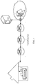
- the collection modules are deployed on a plurality of devices shown in FIG. 6 , and the video service fault may be demarcated in a specific network segment or on a specific device.
- the video service fault may be demarcated in a specific network segment or on a specific device.
- a video quality parameter collected on the ONT exceeds a threshold, it may be considered that the video service fault is caused by a network fault.
- which network segment is faulty may be specifically determined based on video quality parameters reported by two neighboring devices. Specifically, among all the devices transmitting the video stream, a network between any two neighboring devices is referred to as a network segment.
- a fault probability of each network segment is determined, a network segment with a highest fault probability in the network segments is determined, and it may be considered that the video service fault is caused by a fault of the network segment.
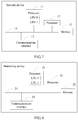
- FIG. 7 is a schematic structural diagram of a network device according to an embodiment of the present invention.
- the network device may be a network device that a monitored video stream flows through in this embodiment of the present invention, for example, a network device such as the BARS, the ONT, the OLT, the CR, or the SIG in the video quality monitoring system shown in FIG. 4 .
- the network device may include at least one processor 11, a memory 12, and a communications interface 13.
- the processor 11 is a control center of the network device, and may be one processor, or may be a collective term for a plurality of processing elements.
- the processor 11 is a central processing unit (central processing unit, CPU), or may be an application-specific integrated circuit (Application-Specific Integrated Circuit, ASIC), or one or more integrated circuits configured to implement this embodiment of the present invention, for example, one or more microprocessors (digital signal processor, DSP), or one or more field programmable gate arrays (Field Programmable Gate Array, FPGA).
- the processor 11 may perform various functions of the network device by running or executing a software program stored in the memory 12 and invoking data stored in the memory 12.
- the processor 11 may include one or more CPUs, for example, a CPU 0 and a CPU 1 in FIG. 7 .
- the network device may include a plurality of processors, for example, the processor 11 and a processor 15 in FIG. 7 .
- Each of the processors may be a single-core (single-CPU) processor, or may be a multi-core (multi-CPU) processor.
- the processor herein may be one or more network devices, circuits, and/or processing cores used for processing data (for example, a computer program instruction).
- the memory 12 may be a read-only memory (read-only memory, ROM) or another type of static storage network device capable of storing static information and instructions, or a random access memory (random access memory, RAM) or another type of dynamic storage network device capable of storing information and instructions, or may be an electrically erasable programmable read-only memory (Electrically Erasable Programmable Read-Only Memory, EEPROM), a compact disc read-only memory (Compact Disc Read-Only Memory, CD-ROM), or other compact disc storage or optical disc storage (including a compressed optical disc, a laser disc, an optical disc, a digital versatile disc, a Blu-ray disc, or the like), a magnetic disk storage medium or another magnetic storage network device, or any other medium capable of carrying or storing expected program code in a form of instructions or data structures and capable of being accessed by a computer. This is not limited.
- the memory 12 may exist independently, and is connected to the processor 11 by using a communications bus 14.
- the memory 12 may also be integrated
- the memory 12 is configured to store a software program for executing the solution of the present invention, where the software program is executed under control of the processor 11.
- the communications interface 13 may include two communications interfaces: a sending interface for sending data to an external network device (for example, an upstream network device or a downlink network device neighboring to the network device in FIG. 4 , or the monitoring device shown in FIG. 4 ) and a receiving interface for receiving data from an external network device.
- the network device may receive data and send data separately by using two different communications interfaces.
- the communications interface 13 may integrate a data receiving function and a data sending function into one communications interface, and the communications interface has the data receiving function and the data sending function.
- a structure of the network device shown in FIG. 7 does not constitute a limitation to the network device.
- a quantity of components included may be greater or less than that shown in the figure, or some components are combined, or component arrangements are different.
- the monitored video stream may be a video stream of a specific channel or a video stream of a user terminal.
- a video quality parameter determined by each device in the video quality monitoring system in the following four scenarios is described: a scenario in which no packet loss recovery method is set, a scenario in which only FEC is set, a scenario in which only RET is set, and a scenario in which both FEC and RET are set.
- the device When calculating RTP_LR, the device first creates a cache queue, sorts received Real-Time Transport Protocol (Real-Time Transport Protocol, RTP) packets (that is, the source packets), then detects a packet loss by using sequence numbers of sorted RTP packet headers, and calculates RTP_LR.
- RTP Real-Time Transport Protocol
- a delay and a jitter in a process of transmitting the RTP packets to the network device cause underflow of a decoder.
- the device may further convert the underflow of the decoder into packet loss processing.
- the underflow of the decoder means that the user terminal has a cache, and if a delay of an RTP packet is very long, the cache becomes empty; in this case, a decoding error occurs in a decoder of the user terminal; and an RTP packet subsequently arriving at the cache of the receive end cannot be decoded but is directly discarded.
- the device may set a size of the cache queue approximately to a size of a decoding cache of the head end device.
- RTP_LR satisfies the following formula (1):
- RTP _ LR losspktNum exp ectedpktNum where losspktNum indicates a quantity of lost RTP packets, and exp ectedpktNum indicates a quantity of RTP packets (that is, the source packets in this embodiment of the present invention) expected to be received.
- RTP_LR losspktNum exp ectedpktNum
- losspktNum indicates a quantity of lost RTP packets
- exp ectedpktNum indicates a quantity of RTP packets (that is, the source packets in this embodiment of the present invention) expected to be received.
- a quantity of source packets expected to be received is also t. 2.
- video quality parameters determined by the device include RTP_LR and an effective packet loss factor in a scenario of FEC.
- ELF_F Effective Loss Factor for FEC
- a value range of ELF_F is 0 ⁇ ELF_F ⁇ 1.
- a plurality of source packets corresponding to the video source need to be grouped into a plurality of source blocks of a same size, where a quantity of source packets included in each source block is the same. For example, every 100 source packets are grouped into one source block. Further, a plurality of redundant packets are encoded and generated for each source block, and a quantity of redundant packets corresponding to each source block is the same.
- L is a source block length that is set when FEC is used for packet loss recovery, that is, the quantity of source packets included in each source block, for example, 100.
- 1 K ⁇ k x l k in the formula (2) is an average value obtained after summation of x 1 (1) to x l ( K ),
- K in the formula (2) is a quantity of monitoring windows, the monitoring windows include first ⁇ N / L ⁇ windows obtained by dividing N source packets based on the source block length by using an l th source packet in a monitoring period as a start point, and the N source packets are all source packets that are included from the l th source packet in the monitoring period to a last source packet in the monitoring period. It should be noted that, the N source packets include the l th source packet and the last source packet in the monitoring period.
- R is a maximum quantity of lost packets that can be recovered for L source packets by using FEC, and is usually a quantity of redundant packets of a single source block that is set when FEC is used for packet loss recovery. For example, if five redundant packets are encoded and generated for each source block, R is 5.
- Num l ( k ) indicates a quantity of lost packets in a k th window during an l th slide, that is, a quantity of lost packets in the k th window in the K monitoring windows
- R is a quantity of redundant packets of a single source block that is set when FEC is used for packet loss recovery. It should be noted that, the slide is window division based on the source block length by using a source packet as a start point in a sequence of transmitting source packets.
- window division during an l th slide means dividing every five source packets into one window by using an l th source packet in the 100 source packets as a start point; and source block division during an eighth slide means dividing every five source packets into one window by using an eighth source packet in the 100 source packets as a start point.
- the monitoring period may be an observation period that is manually set, for example, 10s. 3.
- video quality parameters determined by the device include a packet loss rate RTP_LR, a maximum consecutive packet loss length RTP_LP, and an effective packet loss factor in a scenario of RET and FEC, that is, a second effective packet loss factor described in this embodiment of the present invention.
- Both n and m may indicate effectiveness of recovering a lost network packet by using RET and FEC. Subsequently a method for calculating the second effective packet loss factor is described only by using an example in which the second effective packet loss factor is an effective packet loss factor ELF_FR (effective loss factor for FEC and RET) used to indicate a probability of failing to perform packet loss recovery by using RET and FEC.
- ELF_FR effective packet loss factor for FEC and RET
- L is a source block length that is set when FEC is used for packet loss recovery; for any l greater than 0 and less than or equal to L, K is a quantity of corresponding monitoring windows, the monitoring windows include first ⁇ N /L ⁇ windows obtained by dividing the N source packets based on the preset window length by using an l th source packet in the monitoring period as a start point, and the N source packets are all source packets that are included from the l th source packet in the monitoring period to a last source packet in the monitoring period; and lost (k) is a quantity of source packets that cannot be recovered in a k th window in the K monitoring windows by using FEC, ⁇ is a maximum quantity of lost packets that can be recovered for E source packets by using RET, and E is a quantity of source packets in one monitoring period, that is, a quantity of source packets expected to be received in one monitoring period.
- lost ( k ) is actually a total quantity of lost packets in the k th window. As long as one of the lost packets in the k th window can be recovered, all the lost packets in the window can be recovered, and lost(k) is 0.
- x ( l ) may also be ⁇ k lost k E .
- ⁇ is a ratio of the maximum quantity of lost packets that can be recovered for the E source packets by using RET to the quantity E of source packets expected to be received.
- ELF_FR satisfies the following formula (4):
- ELF_FR 1 L ⁇ l 1 K ⁇ k y l k
- y l k ⁇ 1 x ′ l k > R 0 x ′ l k ⁇ R
- x ′ l k ⁇ x l k ⁇ E ′ x l k ⁇ E ′ 0 x l k ⁇ E ′
- L is a source block length that is set when FEC is used for packet loss recovery; for any l greater than 0 and less than or equal to L, 1 K ⁇ k y l k is an average value obtained after summation of y l (1) to y l ( K ), K is a quantity of monitoring windows, the monitoring windows include first ⁇ N / L ⁇ windows obtained by dividing the N source packets based on the preset window length by using an l th source packet in the monitoring period as a start point, and the N source packets are all source packets that are included from the l th source packet in the monitoring period to a last source packet in the monitoring period; and x l ( k ) is a quantity of lost packets in a k th window in the K monitoring windows, E ' is a quantity of source packets that can be recovered in the k th window by using FEC, and R is a maximum quantity of lost packets that can be recovered for
- video quality parameters determined by the device include a packet loss rate RTP_LR, a maximum consecutive packet loss length (maximum consecutive loss period, RTP_LP), and a third effective packet loss factor.
- the third effective packet loss factor is an effective packet loss factor ELF_R (effective loss factor for RET) used to indicate a probability of failing to perform packet loss recovery by using RET.
- ELF_R effective packet loss factor for RET
- RTP_LP is a maximum value of consecutive packet loss quantities.
- the consecutive packet loss quantities are specifically as follows: A first consecutive packet loss quantity is 2, a second consecutive packet loss quantity is 2, and a third consecutive packet loss quantity is 4. Therefore, RTP_LP is 4.
- ELF_R 1 L ⁇ l 1 K ⁇ k x l k
- x l k ⁇ 1 Num l k > R 0 Num l k ⁇ R , and 0 ⁇ l ⁇ L ,0 ⁇ k ⁇ K.
- L is a preset window length, and may be considered as a quantity of source packets included in one window. For example, if it is specified in advance that 100 source packets are included in one window, L is set to 100.
- 1 K ⁇ k x l k is an average value obtained after summation of x l (1) to x l ( K )
- K is a quantity of monitoring windows
- the monitoring windows include first ⁇ N / L ⁇ windows obtained by dividing N source packets based on the preset window length by using an l th source packet in a monitoring period as a start point
- the N source packets are all source packets that are included from the l th source packet in the monitoring period to a last source packet in the monitoring period
- Num l (k) is a quantity of lost packets in a k th window in the K monitoring windows.
- Num 2 (5) represents a quantity of lost packets obtained in a fifth window when every 10 source packets are divided into one window by using a second source packet in the 100 source packets as a start point.
- R is a maximum quantity of lost packets that can be recovered for the L source packets by using FEC. For example, if L is 100, and assuming that a maximum of five packets in every 100 packets are retransmitted, R is 5.
- the monitoring windows in the foregoing four scenarios may further include a first window.
- the first window is a window constituted by source packets before the l th source packet.
- source packets in the first window are all source packets before the l th source packet in the monitoring period.
- the first window is used as a monitoring window only when a quantity of source packets in the first window is greater than a first threshold.
- the first threshold may be set to ⁇ L /2 ⁇ .
- the monitoring windows further include a second window.
- the second window is a last window in the windows obtained through window division by using the l th source packet in the monitoring period as the start point.
- the second window is used as a monitoring window only when a quantity of source packets in the second window is greater than a second threshold.
- the second threshold and the first threshold may be a same value, for example, may be set to ⁇ L /2 ⁇ .
- source packets whose sequence numbers are 1 to 8 fall within one monitoring period, and a window length (which may be the source block length or the preset window length) is 3.
- Window division is performed by using a second source packet as a start point, that is, using a source packet whose sequence number is 2 as the start point, and windows obtained through division are [source packet whose sequence number is 2, source packet whose sequence number is 3, source packet whose sequence number is 4], [source packet whose sequence number is 5, source packet whose sequence number is 6, source packet whose sequence number is 7], and [source packet whose sequence number is 8].
- Seven source packets are included in total from the second source packet to a last source packet in the monitoring period, and therefore N is 7.
- the monitoring windows are [source packet whose sequence number is 2, source packet whose sequence number is 3, source packet whose sequence number is 4], and [source packet whose sequence number is 5, source packet whose sequence number is 6, source packet whose sequence number is 7].
- the first window is a window constituted by a source packet before the second source packet
- the source packet in the first window is a source packet whose sequence number is 1
- the first window may also be used as a monitoring window.
- the first threshold is 2, and whether to use the first window as a monitoring window is determined based on the first threshold, the first window cannot be used as a monitoring window because a quantity of source packets in the first window is 1.
- the second window is a last window in the windows obtained through window division by using the second source packet in the monitoring period as the start point, a source packet in the second window is the source packet whose sequence number is 8, and the second window may be used as a monitoring window.
- the second threshold is 2, and whether to use the second window as a monitoring window is determined based on the second threshold, the second window cannot be used as a monitoring window because a quantity of source packets in the second window is 1.
- the monitoring windows include only first ⁇ N / L ⁇ windows after the l th source packet. It is assumed that the source packets whose sequence numbers are 1 to 7 fall within one monitoring period, and that the window length is 3.
- the monitoring windows include [source packet whose sequence number is 1, source packet whose sequence number is 2, source packet whose sequence number is 3], and [source packet whose sequence number is 4, source packet whose sequence number is 5, source packet whose sequence number is 6], and K is 2.
- the monitoring windows include [source packet whose sequence number is 3, source packet whose sequence number is 4, source packet whose sequence number is 5], and K is 1.
- monitoring periods or windows are performed based on sequence numbers of source packets, that is, lost network packets are also divided into a monitoring period or a window.
- source packets in a monitoring period are 10 source packets whose sequence numbers are 11 to 20, the source block length is 3, and a source packet whose sequence number is 18 is lost in a transmission process.
- obtained windows are [source packet whose sequence number is 12, source packet whose sequence number is 13, source packet whose sequence number is 14], [source packet whose sequence number is 15, source packet whose sequence number is 16, source packet whose sequence number is 17], and [source packet whose sequence number is 18, source packet whose sequence number is 19, source packet whose sequence number is 20].
- FIG. 8 is a schematic structural diagram of a monitoring device according to an embodiment of the present invention.
- the monitoring device may be the monitoring device in the video quality monitoring system shown in FIG. 4 .
- the monitoring device may include at least one processor 21, a memory 22, and a communications interface 23.
- the processor 21 is a control center of the monitoring device, and may be one processor, or may be a collective term for a plurality of processing elements.
- the processor 21 is a central processing unit (central processing unit, CPU), or may be an application-specific integrated circuit (Application-Specific Integrated Circuit, ASIC), or one or more integrated circuits configured to implement this embodiment of the present invention, for example, one or more microprocessors (digital signal processor, DSP), or one or more field programmable gate arrays (Field Programmable Gate Array, FPGA).
- the processor 21 may perform various functions of the monitoring device by running or executing a software program stored in the memory 22 and invoking data stored in the memory 22.
- the processor 21 may include one or more CPUs, for example, a CPU 0 and a CPU 1 in FIG. 8 .
- the monitoring device may include a plurality of processors, for example, the processor 21 and a processor 25 in FIG. 4 .
- Each of the processors may be a single-core (single-CPU) processor, or may be a multi-core (multi-CPU) processor.
- the processor herein may be one or more devices, circuits, and/or processing cores used for processing data (for example, a computer program instruction).
- the memory 22 may be a read-only memory (read-only memory, ROM) or another type of static storage device capable of storing static information and instructions, or a random access memory (random access memory, RAM) or another type of dynamic storage device capable of storing information and instructions, or may be an electrically erasable programmable read-only memory (Electrically Erasable Programmable Read-Only Memory, EEPROM), a compact disc read-only memory (Compact Disc Read-Only Memory, CD-ROM), or other compact disc storage or optical disc storage (including a compressed optical disc, a laser disc, an optical disc, a digital versatile disc, a Blu-ray disc, or the like), a magnetic disk storage medium or another magnetic storage device, or any other medium capable of carrying or storing expected program code in a form of instructions or data structures and capable of being accessed by a computer. This is not limited.
- the memory 22 may exist independently, and is connected to the processor 21 by using a communications bus 24.
- the memory 22 may also be integrated with the
- the memory 22 is configured to store a software program for executing the solution of the present invention, where the software program is executed under control of the processor 21.
- the communications interface 23 may include two communications interfaces: a sending interface for sending data to an external device (for example, a network device that a monitored video stream flows through, such as the BARS or the ONT shown in FIG. 4 ) and a receiving interface for receiving data from an external device.
- an external device for example, a network device that a monitored video stream flows through, such as the BARS or the ONT shown in FIG. 4
- the monitoring device may receive data and send data separately by using two different communications interfaces.
- the communications interface 23 may further integrate a data receiving function and a data sending function into one communications interface, and the communications interface has the data receiving function and the data sending function.
- a structure shown in FIG. 8 does not constitute a limitation to the monitoring device.
- a quantity of components included may be greater or less than that shown in the figure, or some components are combined, or component arrangements are different.
- the processor 21 invokes code in the memory 22 to monitor video quality of the monitored video stream, and further perform fault detection.
- the communications interface 23 sends a video quality parameter request message to at least one network device that the monitored video stream flows through, where the request includes information of the monitored video stream.
- a scenario in a specific implementation may be the scenario shown in FIG. 5 , collection modules are deployed on the ONT and the SIG, and the at least one network device may be the ONT or the SIG. It may be considered that the ONT is a network device nearest to the user terminal, and that the SIG is a network device nearest to the head end device.
- the scenario may also be the scenario shown in FIG. 6 , and the at least one network device includes the BARS, the ONT, the OLT, the CR, or the SIG.
- the processor 21 obtains, by using the communications interface 23, a video quality parameter that is of the monitored video stream and is monitored by the at least one network device that the monitored video stream flows through.
- the video quality parameter is determined, according to a packet loss recovery method of the monitored video stream, by the network device that the monitored video stream flows through.
- a packet loss recovery method of the monitored video stream by the network device that the monitored video stream flows through.
- the processor 201 of the monitoring device obtains video quality parameters that are of the monitored video stream and are monitored by a first device and a second device, assuming that the first device is the SIG and the second device is the ONT, as in the deployment scenario shown in FIG. 5 , after the communications interface 23 sends a video quality parameter request message to the ONT and the SIG, and the ONT determines that at least one of video quality parameters monitored by the ONT exceeds a corresponding threshold, the ONT reports the video quality parameter to the monitoring device. To be specific, if one of a plurality of video quality parameters exceeds a corresponding threshold, the video quality parameter may be reported, or the plurality of video quality parameters may be reported together.
- video quality parameters determined by the ONT include a packet loss rate RTP_LR and a first effective packet loss factor ELF_F; and if the packet loss rate RTP_LR exceeds a threshold corresponding to the packet loss rate, the ONT reports RTP_LR to the monitoring device, or may report ELF_F.
- the threshold corresponding to the packet loss rate in the scenario in which no packet loss recovery method is set is different from that in the scenario in which a packet loss recovery method is set. For example, the threshold corresponding to the packet loss rate in the scenario in which no packet loss recovery method is set is less than the threshold corresponding to the packet loss rate in the scenario in which a packet loss recovery method is set.
- video quality parameters determined by the SIG include the packet loss rate RTP_LR and the first effective packet loss factor ELF_F. If the packet loss rate RTP_LR exceeds the threshold corresponding to the packet loss rate, the ONT reports RTP_LR to the monitoring device, or may report ELF_F.
- each device determines video quality parameters monitored by the device and then reports all the monitored video quality parameters to the monitoring device.
- the packet loss recovery method set for the monitored video stream device is FEC
- the video quality parameters determined by the ONT include the packet loss rate RTP_LR and the first effective packet loss factor ELF_F, the BARS, the ONT, the OLT, the CR, the SIG, and the like report respectively monitored RTP_LR and ELF_F to the monitoring device.
- the processor 21 performs fault detection based on a video quality parameter that is of the monitored video stream and is sent by at least one network device that the monitored video stream flows through. Specifically, in the scenario shown in FIG. 5 , if the monitoring device receives, in a monitoring period, the video quality parameter reported by the first device, it indicates that a fault occurs between the first device and the head end device.
- the first device is the SIG; and when the monitoring device receives the video quality parameter reported by the SIG, the monitoring device determines that a fault occurs on the head end device.
- the processor 21 receives, in a monitoring period by using the communications interface 23, the video quality parameter reported by the second device but does not receive the video quality parameter reported by the first device, it indicates that a fault occurs between the first device and the second device.
- the first device is the SIG and the second device is the ONT; and when the monitoring device does not receive, in a monitoring period, the video quality parameter reported by the SIG but receives the video quality parameter reported by the ONT, the monitoring device determines that a network fault occurs between the SIG and the ONT.
- the processor 21 does not receive, in the monitoring period by using the communications interface 23, the video quality parameter reported by the first device and the video quality parameter reported by the second device, it indicates that no fault occurs upstream of the second device (including the second device), and the video service fault is caused by a fault between the second device and the user terminal.
- the first device is the SIG
- the second device is the ONT
- the ONT is directly connected to the user terminal (for example, an STB). Therefore, it may be determined that the video service fault is caused by a fault of the user terminal.
- a probability of receiving, by the processor 21 in at least two consecutive monitoring periods, a first video quality parameter reported by the first device is greater than or equal to a third threshold
- the processor 21 determines that a fault occurs between the first device and the head end device.
- the third threshold is 70%; assuming that the processor 21 receives, in three of four consecutive monitoring periods, the first video quality parameter reported by the first device, that is, a probability of receiving the first video quality parameter is 75%, which is greater than 70%, the processor 21 determines that a fault occurs between the first device and the head end device.
- the processor 21 determines that a network fault occurs between the first device and the second device.
- the processor 21 determines that a network fault occurs between the second device and the user terminal.
- the processor 21 receives the video quality parameter reported by each device that the monitored video stream flows through, and performs fault detection based on the video quality parameter reported by each device. Specifically, the processor determines, based on the video quality parameters reported by the ONT and the SIG, whether a fault occurs on the user terminal, or occurs on the head end device, or occurs in a network transmitting the video stream. Once it is determined that the fault occurs in the network, fault detection may be performed on a specific network segment based on video quality parameters reported by every two neighboring devices. For example, the processor 21 determines a fault probability of each network segment, and determines a network segment with a highest fault probability as a network segment that causes the video service fault.
- the network segment is a network segment between two devices that the monitored video stream flows through, and is determined based on ports on which probes are deployed in the two devices in a specific implementation. For example, if the probes of the two devices are both deployed on outbound interfaces, a network segment between the two devices is a network segment between the outbound interfaces of the two devices.
- FIG. 9 is a flowchart of a fault detection method according to an embodiment of the present invention. As shown in FIG. 9 , the method may include the following steps.
- a monitoring device sends a video quality parameter request message to at least one network device that a monitored video stream flows through, where the video quality parameter request message is used to indicate an identifier of the monitored video stream and a packet loss recovery method of the monitored video stream.
- the at least one network device may include an ONT (that is, a second device described in this embodiment of the present invention) nearest to a user terminal and a SIG (that is, a first device described in this embodiment of the present invention) nearest to a head end device, or may include devices that the monitored video stream flows through, for example, a BARS, an ONT, an OLT, a CR, and a SIG.
- the packet loss recovery method of the monitored video stream may be considered as a packet loss recovery method set for the monitored video stream. When a network packet loss occurs in a process of transmitting the monitored video stream, the packet loss recovery method of the monitored video stream may be used to recover a lost network packet.
- the identifier of the monitored video stream may be a channel number or a multicast address and a port; or if the monitored video stream is an on-demand video stream, the identifier of the monitored video stream may be a quintuple, for example, a source Internet Protocol (Internet Protocol, IP) address, a source port, a destination IP address, a destination port, and a transport-layer protocol.
- IP Internet Protocol
- the monitored video stream may be a video stream corresponding to a specific channel or a video stream corresponding to a user terminal. If the monitored video stream may be a video stream corresponding to a specific channel, information of the monitored video stream includes channel information, whether a FEC function is enabled on the channel, a size of a FEC coding matrix, a quantity of redundant packets of a single source block, and whether a user terminal (such as an STB) supports a FEC function. If the monitored video stream is for a user terminal, information of the monitored video stream includes whether the terminal has a RET function, information such as a RET retransmission limit (that is, ⁇ ), a decoding parameter (a cache capacity) related to the terminal, and the like.
- RET function information such as a RET retransmission limit (that is, ⁇ )
- decoding parameter a cache capacity
- Each of the at least one network device determines a video quality parameter according to the packet loss recovery method of the monitored video stream.
- the video quality parameter includes an effective packet loss factor, used to indicate effectiveness of network packet loss recovery performed by using the packet loss recovery method of the monitored video stream.
- each network device determines, based on the received video quality parameter request message, the identifier of the monitored video stream and the packet loss recovery method of the monitored video stream, and further determines, based on the packet loss recovery method of the monitored video stream, a video quality parameter that needs to be collected. Specifically, if the packet loss recovery method of the monitored video stream is FEC, the video quality parameter is at least one of a packet loss rate and a first effective packet loss factor (the effective packet loss factor in step 102) determined by the network device that the monitored video stream flows through.
- the video quality parameter is at least one of the packet loss rate and the maximum consecutive packet loss quantity determined by the network device that the monitored video stream flows through.
- the video quality parameter is at least one of a packet loss rate, a maximum consecutive packet loss quantity, and a second effective packet loss factor (the effective packet loss factor in step 102) determined by the network device that the monitored video stream flows through.
- the packet loss rate satisfies the foregoing formula (1)
- the first effective packet loss factor ELF_F satisfies the foregoing formula (2)
- the second effective packet loss factor RTP_FR satisfies the foregoing formula (3) or (4)
- the third effective packet loss factor ELF_R satisfies the foregoing formula (5).
- the monitoring device obtains the video quality parameter that is of the monitored video stream and is monitored by the at least one network device that the monitored video stream flows through.
- the at least one network device may be the second device nearest to user equipment among network devices that the monitored video stream flows through, and the first device nearest to the head end device among the network devices that the monitored video stream flows through, as in the deployment scenario shown in FIG. 5 .
- the first device reports the first video quality parameter to the monitoring device. Specifically, if one of a plurality of video quality parameters included in first video quality parameters exceeds a corresponding threshold, the video quality parameter may be reported, or the plurality of video quality parameters included in the first video quality parameters may be reported together.
- the video quality parameters determined by the first device include a packet loss rate RTP_LR and a first effective packet loss factor ELF_F; and if the packet loss rate RTP_LR exceeds a threshold corresponding to the packet loss rate, the ONT reports RTP_LR to the monitoring device, or may report ELF_F.
- the threshold corresponding to the packet loss rate in a scenario in which no packet loss recovery method is set is different from that in a scenario in which a packet loss recovery method is set.
- the threshold corresponding to the packet loss rate in the scenario in which no packet loss recovery method is set is less than the threshold corresponding to the packet loss rate in the scenario in which a packet loss recovery method is set.
- video quality parameters determined by the second device include the packet loss rate RTP_LR and the first effective packet loss factor ELF_F. If the packet loss rate RTP_LR exceeds the threshold corresponding to the packet loss rate, the ONT reports RTP_LR to the monitoring device, or may report ELF_F.
- the at least one network device may be N (N is an integer greater than or equal to 2) devices that the monitored video stream flows through, as in the deployment scenario shown in FIG. 6 .
- the N network devices determine video quality parameters monitored by the N network devices, and report all the monitored video quality parameters to the monitoring device in a monitoring period. For example, if the packet loss recovery method set for the monitored video stream device is FEC, and the video quality parameters determined by the N network devices include the packet loss rate RTP_LR and the first effective packet loss factor ELF_F, the N network devices report respectively monitored RTP_LR and ELF_F to the monitoring device.
- the monitoring device performs fault detection based on the video quality parameter that is of the monitored video stream and is monitored by the at least one network device.
- the monitoring device determines that a fault occurs on the head end device; or if the monitoring device receives, in the monitoring period, the video quality parameter reported by the second device but does not receive the video quality parameter reported by the first device, the monitoring device may determine that a network fault occurs between the second device and the first device; or if the monitoring device does not receive, in the monitoring period, the video quality parameter reported by the first device and the video quality parameter reported by the second device, the monitoring device determines that a fault occurs on the user terminal.
- the monitoring device receives the video quality parameter that is of the monitored video stream and is sent by each of the N network devices.
- the monitoring device may perform fault detection based on the parameter reported by each device. Specifically, if at least one of the video quality parameters reported by the first device exceeds a corresponding threshold, the monitoring device determines that a fault occurs on the head end device; or if none of the video quality parameters reported by the first device exceeds a corresponding threshold, but at least one of the video quality parameters reported by the second device exceeds a corresponding threshold, the monitoring device may determine that a network fault occurs between the second device and the first device; or if none of the video quality parameters reported by the first device and the video quality parameters reported by the second device exceeds a corresponding threshold, the monitoring device determines that a fault occurs on the user terminal.
- the monitoring device may further locate the fault in a network segment based on video quality reported by each device.
- the first device, the M third devices, and the second device are a first device, a second device, ..., an i th device, an (i+1) th device, ..., an (M+2) th device respectively in sequence from upstream to downstream.
- a network segment is formed between any two neighboring devices among the M+2 devices.
- M+1 network segments may be determined between the first device, the M third devices, and the second device.
- the M+1 network segments are a first network segment, a second network segment, ..., an i th network segment, an (i+1) th network segment, ..., an (M+1) th network segment respectively in sequence from upstream to downstream.
- a network segment between the i th device and the (i+1) th device is the i th network segment.
- i is an integer greater than or equal to 1 and less than or equal to M+1.
- the monitoring device may determine the fault probability of each network segment according to the following steps:
- p i Q ⁇ ⁇ i Q / ⁇ i ⁇ i Q , ⁇ i ⁇ i Q > ⁇ Q 0 , ⁇ i ⁇ i Q ⁇ ⁇ Q
- ⁇ i Q ⁇ i + 1 Q ⁇ ⁇ i Q
- ⁇ i + 1 Q is a Q th parameter reported by the (i+1) th device
- ⁇ i Q is a Q th parameter reported by the i th device
- ⁇ Q is a threshold corresponding to the Q th parameter
- the (i+1) th device is an upstream device neighboring to the i th device
- An embodiment of the present invention further provides a fault detection method.
- video fault detection modules and collection modules are deployed on a SIG and an ONT.
- the method may include the following steps.
- a monitoring device is responsible for sending a video quality parameter request message to a video fault detection module deployed on a SIG or an ONT.
- the request is used to instruct a collection module deployed on the SIG or the ONT to collect a video quality parameter of a monitored video stream (such as a specific channel or user terminal) to monitor video quality of a specific channel or user terminal, and the instruction is used to indicate an identifier of the monitored video stream and a packet loss recovery method of the monitored video stream.
- a video quality parameter of a monitored video stream such as a specific channel or user terminal
- the video fault detection module receives the video quality parameter request message, determines, based on the message, whether a FEC or RET function is enabled for a monitored video stream, and selects corresponding video quality parameters based on whether the FEC or RET function is enabled.
- a collection module collects the selected video quality parameters based on a specified monitoring period.
- the collection module periodically reports the collected video quality parameters to the video fault detection module, and the video fault detection module compares the collected video quality parameters with corresponding thresholds, and reports a fault to the monitoring device if one of the parameters exceeds a threshold.
- a parameter that exceeds the threshold may be reported, or all monitored parameters may be reported together to the monitoring device.
- the monitoring device collects fault probabilities in a plurality of consecutive monitoring periods, and compares the fault probabilities with corresponding thresholds.
- collecting fault probabilities in a plurality of consecutive monitoring periods is calculating probabilities of reporting faults by devices in the plurality of consecutive periods. For example, if the SIG reports faults in three of four consecutive periods, a fault probability of the SIG in the four consecutive periods is 3/4, that is, 75%.
- a fault probability of the SIG exceeds a threshold, consider that a video service fault is caused by incorrect content of a video head end; if a fault probability of the ONT exceeds a threshold, consider that a video service fault is caused by network transmission; otherwise, consider that a video service fault is caused by a fault of a user terminal.
- collection modules are respectively deployed on a most upstream device and a most downstream device that the monitored video stream flows through; and the two devices monitor different video quality parameters according to different packet loss recovery methods (FEC and RET) used by an operator.
- the parameters are determined according to the used packet loss recovery method. Because compensation of the packet loss recovery method for a packet loss in network transmission is considered, impact of network transmission quality on video service quality is accurately reflected. Further, the monitoring device can accurately determine the impact of network transmission quality on video service quality based on a video quality parameter reported by a device, and therefore accuracy of fault detection on a video service is improved.
- the video quality parameters are reported to the monitoring device, that is, at least one of the video quality parameters reported by the ONT exceeds a corresponding threshold, for example, a packet loss rate is higher than a corresponding threshold, but a first packet loss factor reported by the ONT is less than a corresponding threshold, that is, FEC is used to compensate for adverse impact of the network packet loss on the video service. Therefore, the monitoring device may consider that the video service fault is not caused by network transmission.
- An embodiment of the present invention further provides a fault detection method.
- collection modules are deployed on an ONT, an OLT, a BARS, a CR, and a SIG, and a video fault detection module is deployed on a monitoring device.
- the method may include the following steps.
- a monitoring device is responsible for sending a video quality parameter request message to a video fault detection module deployed on each network device deployed with a collection module.
- the monitoring device sends the video quality parameter request message to each of an ONT, an OLT, a BARS, a CR, and a SIG.
- the request is used to instruct a collection module deployed on the SIG or the ONT to collect a video quality parameter of a monitored video stream (such as a specific channel or user terminal) to monitor video quality of a specific channel or user terminal, and the instruction is used to indicate an identifier of the monitored video stream and a packet loss recovery method of the monitored video stream.
- the video fault detection module receives the video quality parameter request message, determines, based on the message, whether a FEC or RET function is enabled for a monitored video stream, and selects corresponding video quality parameters based on whether the FEC or RET function is enabled.
- the collection module collects video quality parameters based on a specified monitoring period, and reports all the collected parameters to the monitoring device.
- the monitoring device sorts each device in a sequence from upstream to downstream, and compares a video quality parameter collected by a most downstream device with a corresponding threshold.
- the monitoring device uses a service path restoration method to perform upstream-to-downstream sorting on each device.
- the monitoring device determines that the video quality parameter reported by the most downstream device exceeds the threshold (a parameter may exceed a threshold or a plurality of parameters may exceed thresholds), the monitoring device determines that a video service fault is caused by network transmission, and performs a subsequent demarcation step, that is, step 306; otherwise, the monitoring device determines that a video service fault is not caused by network transmission, and performs step 305.
- the threshold a parameter may exceed a threshold or a plurality of parameters may exceed thresholds
- the monitoring device determines that a video quality parameter reported by a SIG exceeds a threshold, the monitoring device considers that a video service fault is caused by a fault of a HE; otherwise, the monitoring device considers that a video service fault is caused by a fault of an STB.
- the monitoring device calculates a fault probability of each network segment, and determines a network segment with a highest fault probability as a network segment that causes the video service fault.
- network devices that the monitored video stream flows through are five devices: the ONT, the OLT, the BARS, the CR, and the SIG, and four network segments in total are determined.
- a method for calculating a fault probability according to this embodiment of the present invention is described by using a first network segment (that is, a network segment between the CR and the SIG) as an example.
- video quality parameters determined by the CR and the SIG include a packet loss rate RTP_LR and a first effective packet loss factor ELF_F.
- ⁇ 1 1 is a packet loss rate reported by the SIG
- ⁇ 2 1 is a packet loss rate reported by the CR
- ⁇ 4 1 is a packet loss rate reported by the OLT
- ⁇ 5 1 is a packet loss rate reported by the ONT.
- ⁇ 1 2 is a packet loss rate reported by the SIG
- ⁇ 2 2 is a packet loss rate reported by the CR
- ⁇ 3 2 is a packet loss rate reported by the BARS
- ⁇ 4 2 is a packet loss rate reported by the OLT
- ⁇ 5 2 is a packet loss rate reported by the ONT.
- a larger one of P 1 and P 2 is used as a fault probability of the first network segment.
- a fault probability of a second network segment, a fault probability of a third network segment, and a fault probability of a fourth network segment are calculated, and a network segment with a highest fault probability is determined as a network segment that causes the video service fault.
- the monitoring device may further calculate a probability of each network segment causing the video service fault in a plurality of consecutive monitoring periods, and updates the fault probability of the network segment to a probability of the network segment causing the video service fault in the plurality of consecutive monitoring periods.
- a fault probability in a first monitoring period is P 1
- a fault probability in a second monitoring period is P 2
- a fault probability in a third monitoring period is P 3 ; in addition, the first monitoring period is nearest to the fault time point, the second monitoring period is nearer to the fault time point, and the third monitoring period is farthest from the fault time point.
- the fault probability of the first network segment calculated in step 306 is updated to: ( P 1 ⁇ 1/2 + P 2 ⁇ 1/4 + P 3 ⁇ 1/8)/( p 1 ' + p 2 ' + p 3 ' + p 4 ' ), where p 2 ' is a fault probability of the second network segment, p 3 ' is a fault probability of the third network segment, and p 4 ' is a fault probability of the second network segment.
- a collection module is deployed on each network device transmitting the video stream; and the devices monitor different video quality parameters according to different packet loss recovery methods (FEC and RET) used by an operator.
- the parameters are determined according to the used packet loss recovery method. Because compensation of the packet loss recovery method for a packet loss in network transmission is considered, impact of network transmission quality on video service quality is accurately reflected. Further, the monitoring device can accurately determine the impact of network transmission quality on video service quality based on a video quality parameter reported by a device, and therefore accuracy of fault detection on a video service is improved.
- the monitoring device may consider that the video service fault is not caused by network transmission.
- the monitoring device and the device in the embodiments of the present invention include corresponding hardware structures and/or software modules for performing the functions.
- the present invention can be implemented by hardware or a combination of hardware and computer software. Whether a function is performed by hardware or hardware driven by computer software depends on particular applications and design constraints of the technical solutions. A person skilled in the art may use different methods to implement the described functions for each particular application, but it should not be considered that the implementation goes beyond the scope of the present invention.
- each functional module may be defined in a correspondence to each function, or two or more functions may be integrated into one processing module.
- the integrated module may be implemented in a form of hardware, or may be implemented in a form of a software functional module. It should be noted that, module division in the embodiments of the present invention is an example, and is merely logical function division. There may be other division in an actual implementation.
- FIG. 12 is a possible schematic structural diagram of the monitoring device used in the foregoing embodiment.
- the monitoring device may include a sending unit 401, an obtaining unit 402, and a detection unit 403.
- the sending unit 401 is configured to support the monitoring device in performing step 101 in the fault detection method shown in FIG. 9 , step 201 in the fault detection method shown in FIG. 10 , and step 301 in the fault detection method shown in FIG. 11A .
- the obtaining unit 402 is configured to support the monitoring device in performing step 103 in the fault detection method shown in FIG. 9 and step 204 in the fault detection method shown in FIG. 10 , and further configured to support the monitoring device in performing step 303 in the fault detection method shown in FIG. 11A .
- the detection unit 403 is configured to support the monitoring device in performing step 104 in the fault detection method shown in FIG. 9 , steps 205 and 206 in the fault detection method shown in FIG. 10 , and steps 304 to 306 in the fault detection method shown in FIG. 11B .
- FIG. 13 is another possible schematic structural diagram of the monitoring device used in the foregoing embodiment.
- the monitoring device includes a processing module 501 and a communications module 502.
- the processing module 501 is configured to control and manage actions of the monitoring device.
- the processing module 501 is configured to support the monitoring device in performing step 104 in the fault detection method shown in FIG. 9 , steps 205 and 206 in the fault detection method shown in FIG. 10 , and steps 304 to 306 in the fault detection method shown in FIG. 11B , and/or used in other processes of the technology described in this specification.
- the communications module 502 is configured to support communication between the monitoring device and another network entity, for example, communication with the SIG or the ONT shown in FIG. 5 .
- the monitoring device may further include a storage module 503, configured to store program code and data of the monitoring device.
- the processing module 501 may be a processor or a controller.
- the controller/processor may implement or execute various example logical blocks, modules, and circuits described with reference to content disclosed in the present invention.
- the processor may be a combination of processors implementing a computing function, for example, a combination of one or more microprocessors, or a combination of a DSP and a microprocessor.
- the communications module 502 may be a transceiver, a transceiver circuit, a communications interface, or the like.
- the storage module 503 may be a memory.
- the monitoring device used in this embodiment of the present invention may be the monitoring device shown in FIG. 8 .
- FIG. 14 is a possible schematic structural diagram of the network device used in the foregoing embodiment.
- the network device may include a receiving unit 601, a determining unit 602, and a sending unit 603.
- the receiving unit 601 is configured to support the device in performing step 101 in the fault detection method shown in FIG. 9 , step 201 in the fault detection method shown in FIG. 10 , and step 301 in the fault detection method shown in FIG. 11A .
- the determining unit 602 is configured to support the device in performing step 102 in the fault detection method shown in FIG. 9 , steps 202 and 203 in the fault detection method shown in FIG. 10 , and step 302 and the step of "collecting video quality parameters based on a specified monitoring period" in step 302 in the fault detection method shown in FIG. 11A .
- the sending unit 603 is configured to support the device in performing step 103 in the fault detection method shown in FIG. 9 , step 204 in the fault detection method shown in FIG. 10 , and the step of "reporting all the collected parameters to the monitoring device" in step 303 in the fault detection method shown in FIG. 11A .
- FIG. 15 is another possible schematic structural diagram of the network device used in the foregoing embodiment.
- the network device includes a processing module 701 and a communications module 702.
- the processing module 701 is configured to control and manage actions of the device.
- the processing module 701 is configured to support the device in performing step 102 in the fault detection method shown in FIG. 9 , steps 202 and 203 in the fault detection method shown in FIG. 10 , and step 302 and the step of "collecting video quality parameters based on a specified monitoring period" in step 302 in the fault detection method shown in FIG. 11A , and/or used in other processes of the technology described in this specification.
- the communications module 702 is configured to support communication between the device and another network entity, for example, communication with the SIG or the ONT shown in FIG. 5 .
- the network device may further include a storage module 703, configured to store program code and data of the device.
- the processing module 701 may be a processor or a controller.
- the controller/processor may implement or execute various example logical blocks, modules, and circuits described with reference to content disclosed in the present invention.
- the processor may be a combination of processors implementing a computing function, for example, a combination of one or more microprocessors, or a combination of a DSP and a microprocessor.
- the communications module 702 may be a transceiver, a transceiver circuit, a communications interface, or the like.
- the storage module 703 may be a memory.
- the network device used in this embodiment of the present invention may be the network device shown in FIG. 7 .
- the terminal provided by this embodiment of this application may be configured to perform the foregoing fault detection method, for a technical effect that can be achieved by the terminal, refer to the foregoing method embodiment. Details are not described again in this embodiment of this application.
- the disclosed system, apparatus, and method may be implemented in other manners.
- the described apparatus embodiment is merely an example.
- the module or unit division is merely logical function division and may be other division in an actual implementation.
- a plurality of units or components may be combined or integrated into another system, or some features may be ignored or may not be performed.
- the displayed or discussed mutual couplings or direct couplings or communication connections may be implemented by using some interfaces.
- the indirect couplings or communication connections between the apparatuses or units may be implemented in electronic, mechanical, or other forms.
- the units described as separate parts may or may not be physically separate, and parts displayed as units may or may not be physical units, may be located in one position, or may be distributed on a plurality of network units. Some or all of the units may be selected based on actual requirements to achieve the objectives of the solutions of the embodiments.
- functional units in the embodiments of this application may be integrated into one processing unit, or each of the units may exist alone physically, or two or more units are integrated into one unit.
- the integrated unit may be implemented in a form of hardware, or may be implemented in a form of a software functional unit.
- the integrated unit When the integrated unit is implemented in the form of a software functional unit and sold or used as an independent product, the integrated unit may be stored in a computer-readable storage medium. Based on such an understanding, the technical solutions of this application essentially, or the part contributing to the prior art, or all or some of the technical solutions may be implemented in the form of a software product.
- the computer software product is stored in a storage medium and includes several instructions for instructing a computer device (which may be a personal computer, a server, a network device, or the like) to perform all or some of the steps of the methods described in the embodiments of this application.
- the foregoing storage medium includes any medium that can store program code, such as a flash memory, a removable hard disk, a read-only memory, a random access memory, a magnetic disk, or an optical disc.
Landscapes
- Engineering & Computer Science (AREA)
- Signal Processing (AREA)
- Computer Networks & Wireless Communication (AREA)
- Multimedia (AREA)
- Databases & Information Systems (AREA)
- Computer Security & Cryptography (AREA)
- Environmental & Geological Engineering (AREA)
- Data Exchanges In Wide-Area Networks (AREA)
- Two-Way Televisions, Distribution Of Moving Picture Or The Like (AREA)
Applications Claiming Priority (2)
| Application Number | Priority Date | Filing Date | Title |
|---|---|---|---|
| CN201710396274.0A CN108965934B (zh) | 2017-05-27 | 2017-05-27 | 一种故障检测方法、监控设备及网络设备 |
| PCT/CN2018/074797 WO2018218985A1 (fr) | 2017-05-27 | 2018-01-31 | Procédé de détection d'anomalie, dispositif de surveillance, et dispositif de réseau |
Publications (4)
| Publication Number | Publication Date |
|---|---|
| EP3624461A1 true EP3624461A1 (fr) | 2020-03-18 |
| EP3624461A4 EP3624461A4 (fr) | 2020-05-20 |
| EP3624461C0 EP3624461C0 (fr) | 2026-03-25 |
| EP3624461B1 EP3624461B1 (fr) | 2026-03-25 |
Family
ID=64456062
Family Applications (1)
| Application Number | Title | Priority Date | Filing Date |
|---|---|---|---|
| EP18809706.7A Active EP3624461B1 (fr) | 2017-05-27 | 2018-01-31 | Procédé de détection d'anomalie, dispositif de surveillance, et dispositif de réseau |
Country Status (4)
| Country | Link |
|---|---|
| US (1) | US11968422B2 (fr) |
| EP (1) | EP3624461B1 (fr) |
| CN (3) | CN112702629B (fr) |
| WO (1) | WO2018218985A1 (fr) |
Families Citing this family (17)
| Publication number | Priority date | Publication date | Assignee | Title |
|---|---|---|---|---|
| CN112702629B (zh) * | 2017-05-27 | 2022-02-11 | 华为技术有限公司 | 一种故障检测方法、监控设备及网络设备 |
| US11153334B2 (en) * | 2019-04-09 | 2021-10-19 | Arbor Networks, Inc. | Automatic detection of malicious packets in DDoS attacks using an encoding scheme |
| WO2020227781A1 (fr) * | 2019-05-16 | 2020-11-19 | Canopus Networks Pty Ltd | Procédé et appareil pour l'estimation d'une qualité d'expérience en temps réel |
| CN112637708A (zh) * | 2019-09-24 | 2021-04-09 | 中兴通讯股份有限公司 | 一种组播业务监控的方法及板卡 |
| WO2021077277A1 (fr) * | 2019-10-22 | 2021-04-29 | Qualcomm Incorporated | Latence de cellule secondaire faisant appel à un profil de latence |
| US20210160125A1 (en) * | 2019-11-26 | 2021-05-27 | Jing Cheng | Systems and methods for fault detection based on peer statistics |
| CN114007132B (zh) * | 2020-07-28 | 2024-09-13 | 中国电信股份有限公司 | 异常检测方法、装置及计算机可读存储介质 |
| TWI730927B (zh) * | 2020-11-20 | 2021-06-11 | 財團法人資訊工業策進會 | 模糊測試裝置及模糊測試方法 |
| US11962868B2 (en) * | 2020-11-30 | 2024-04-16 | Verizon Patent And Licensing Inc. | Detecting a quality issue associated with a video stream delivery |
| CN112653887B (zh) * | 2020-12-14 | 2023-03-10 | 中国联合网络通信集团有限公司 | 一种视频诊断的方法及装置 |
| CN113556579B (zh) * | 2021-06-07 | 2022-08-19 | 武汉众智数字技术有限公司 | 一种基于HTML5的web无插件播放安防实时视频的方法 |
| CN113438106B (zh) * | 2021-06-22 | 2023-02-21 | 北京百度网讯科技有限公司 | 内容分发网络处理方法、装置及电子设备 |
| CN115883887B (zh) * | 2021-09-24 | 2025-09-19 | 中国移动通信集团安徽有限公司 | 互联网电视卡顿原因的确定方法、装置、设备及存储介质 |
| CN114039703B (zh) * | 2021-11-26 | 2023-10-20 | 北京字节跳动网络技术有限公司 | 数据传输方法、装置、设备和介质 |
| CN115908360A (zh) * | 2022-12-07 | 2023-04-04 | 西安震有信通科技有限公司 | 监控视频巡检方法、装置、电子设备及存储介质 |
| US11973634B1 (en) | 2023-01-31 | 2024-04-30 | Dish Network Technologies India Private Limited | Detecting hardware issue |
| CN120658858B (zh) * | 2025-07-17 | 2025-11-25 | 浙江零跑科技股份有限公司 | 视频流故障恢复方法、系统、设备和存储介质 |
Family Cites Families (41)
| Publication number | Priority date | Publication date | Assignee | Title |
|---|---|---|---|---|
| US6421387B1 (en) * | 1998-05-15 | 2002-07-16 | North Carolina State University | Methods and systems for forward error correction based loss recovery for interactive video transmission |
| US20150341812A1 (en) * | 2003-08-29 | 2015-11-26 | Ineoquest Technologies, Inc. | Video quality monitoring |
| US7962637B2 (en) * | 2006-11-03 | 2011-06-14 | Apple Computer, Inc. | Dynamic adjustments of video streams |
| US7821937B1 (en) * | 2007-06-29 | 2010-10-26 | Symantec Corporation | Network protocol with damage loss resilient congestion control algorithm |
| US9191622B2 (en) * | 2007-10-17 | 2015-11-17 | At&T Intellectual Property I, Lp | System for fault detection in an internet protocol television communication system |
| CN101304343B (zh) * | 2008-06-10 | 2012-03-21 | 华为技术有限公司 | 一种网络故障检测的方法、网络设备和网络系统 |
| JP5127062B2 (ja) * | 2009-01-08 | 2013-01-23 | シャープ株式会社 | ネットワーク障害検出装置、データ中継装置、ネットワーク障害検出方法、ネットワーク障害検出システム及びネットワーク障害検出プログラム |
| CN101572829B (zh) * | 2009-06-10 | 2011-02-02 | 中国联合网络通信集团有限公司 | Iptv视频质量监测方法、装置和系统 |
| JP5107971B2 (ja) * | 2009-06-29 | 2012-12-26 | 日本電信電話株式会社 | ユーザ体感品質推定システムおよび方法 |
| CN102065372B (zh) * | 2009-11-16 | 2014-10-08 | 中国移动通信集团公司 | 以广播方式传输数据的方法及相关装置 |
| US20110271307A1 (en) * | 2009-12-18 | 2011-11-03 | Tektronix International Sales Gmbh | Video data stream evaluation systems and methods |
| CN102118653B (zh) * | 2009-12-31 | 2012-12-26 | 华为技术有限公司 | 保障网络电视直播业务的业务服务质量的方法和设备 |
| CN102130821A (zh) * | 2010-08-11 | 2011-07-20 | 华为技术有限公司 | 一种iptv系统中丢包处理的方法、服务器及系统 |
| JP5598155B2 (ja) * | 2010-08-12 | 2014-10-01 | ソニー株式会社 | 情報処理装置および方法、並びに送受信システム |
| CN102137282B (zh) * | 2010-12-15 | 2014-02-19 | 华为技术有限公司 | 一种检测故障链路的方法、装置、节点和系统 |
| US8813144B2 (en) * | 2011-01-10 | 2014-08-19 | Time Warner Cable Enterprises Llc | Quality feedback mechanism for bandwidth allocation in a switched digital video system |
| CN104883563B (zh) * | 2011-04-11 | 2017-04-12 | 华为技术有限公司 | 一种视频数据质量评估方法和装置 |
| US8767821B2 (en) * | 2011-05-09 | 2014-07-01 | Google Inc. | System and method for providing adaptive media optimization |
| US10498359B2 (en) * | 2011-07-14 | 2019-12-03 | Microsoft Technology Licensing, Llc | Correction data |
| JP5969021B2 (ja) * | 2011-08-16 | 2016-08-10 | 華為技術有限公司Huawei Technologies Co.,Ltd. | Iptv障害を見つける方法、装置及びシステム |
| CN103179597B (zh) * | 2011-12-21 | 2016-03-09 | 华为技术有限公司 | 一种无线保真技术的处理方法和用户设备 |
| CN102546263A (zh) * | 2012-02-21 | 2012-07-04 | 德科仕通信(上海)有限公司 | 在iptv网络中视频服务器和ip网络的故障隔离方法及系统 |
| CN102572531B (zh) * | 2012-02-21 | 2014-08-27 | 德科仕通信(上海)有限公司 | 一种iptv网络丢包故障定界方法及系统 |
| CN102769551B (zh) * | 2012-07-02 | 2016-08-10 | 深信服网络科技(深圳)有限公司 | 网络质量评测与网络优化的方法及系统 |
| CN103813160B (zh) * | 2012-11-12 | 2016-03-02 | 中国电信股份有限公司 | 视频质量监控方法和装置 |
| CN103945213B (zh) * | 2013-01-22 | 2016-12-28 | 中兴通讯股份有限公司 | 一种视频流质量监测方法及装置 |
| CN103237314B (zh) * | 2013-04-25 | 2015-12-23 | 中国联合网络通信集团有限公司 | 业务质量评测方法和装置 |
| CN103338471A (zh) * | 2013-06-27 | 2013-10-02 | 南京邮电大学 | 基于模型的无线多跳网络服务质量指标评价方法 |
| CN103686445B (zh) * | 2013-12-03 | 2017-04-19 | 浙江宇视科技有限公司 | 一种视频监控网络中Qos动态调整方法和装置 |
| CN103686446B (zh) * | 2013-12-06 | 2018-09-14 | 广州华多网络科技有限公司 | 视频数据传输的丢包重传方法和系统 |
| RU2640573C1 (ru) * | 2013-12-30 | 2018-01-10 | Хуавей Текнолоджиз Ко., Лтд. | Способ устранения отказа, сеть пакетной передачи данных, узел управления мобильностью и сетевая система |
| CN103957222A (zh) * | 2014-05-20 | 2014-07-30 | 艾诺通信系统(苏州)有限责任公司 | 一种基于fec算法的视频传输自适应方法 |
| CN104052622B (zh) * | 2014-06-23 | 2018-02-23 | 合肥工业大学 | 片上网络中基于故障通道隔离检测的路由器容错方法 |
| CN104159166B (zh) * | 2014-08-07 | 2015-08-05 | 西安交通大学 | 基于移动网络丢包状态的直播视频数据传输差错控制方法 |
| WO2016090632A1 (fr) * | 2014-12-12 | 2016-06-16 | 华为技术有限公司 | Procédé et appareil pour détecter l'état de fonctionnement d'un nœud |
| CN104539941B (zh) * | 2014-12-25 | 2016-12-07 | 南京大学镇江高新技术研究院 | 基于改进代码书的交通视频专网故障定位方法 |
| JP2016146571A (ja) * | 2015-02-09 | 2016-08-12 | Kddi株式会社 | 誤り訂正機能検証装置 |
| CN106549916A (zh) * | 2015-09-18 | 2017-03-29 | 中兴通讯股份有限公司 | 组播传输方法、装置及系统 |
| CN106330930A (zh) * | 2016-08-29 | 2017-01-11 | 烽火通信科技股份有限公司 | 基于流媒体丢包二次重传系统及其方法 |
| CN106452925B (zh) * | 2016-12-02 | 2021-01-05 | 华为技术有限公司 | 在nfv系统中检测故障的方法、装置和系统 |
| CN112702629B (zh) * | 2017-05-27 | 2022-02-11 | 华为技术有限公司 | 一种故障检测方法、监控设备及网络设备 |
-
2017
- 2017-05-27 CN CN202110080568.9A patent/CN112702629B/zh active Active
- 2017-05-27 CN CN202110080867.2A patent/CN112702630B/zh active Active
- 2017-05-27 CN CN201710396274.0A patent/CN108965934B/zh active Active
-
2018
- 2018-01-31 EP EP18809706.7A patent/EP3624461B1/fr active Active
- 2018-01-31 WO PCT/CN2018/074797 patent/WO2018218985A1/fr not_active Ceased
-
2019
- 2019-11-26 US US16/695,652 patent/US11968422B2/en active Active
Also Published As
| Publication number | Publication date |
|---|---|
| EP3624461A4 (fr) | 2020-05-20 |
| US20200099981A1 (en) | 2020-03-26 |
| CN112702629B (zh) | 2022-02-11 |
| CN108965934A (zh) | 2018-12-07 |
| EP3624461C0 (fr) | 2026-03-25 |
| WO2018218985A1 (fr) | 2018-12-06 |
| EP3624461B1 (fr) | 2026-03-25 |
| US11968422B2 (en) | 2024-04-23 |
| CN108965934B (zh) | 2021-01-29 |
| CN112702630B (zh) | 2025-03-25 |
| CN112702629A (zh) | 2021-04-23 |
| CN112702630A (zh) | 2021-04-23 |
Similar Documents
| Publication | Publication Date | Title |
|---|---|---|
| US11968422B2 (en) | Video stream fault detection | |
| JP5051252B2 (ja) | ネットワーク障害検出システム | |
| US8588093B2 (en) | Streaming communication device, streaming communication method, and streaming communication system | |
| US8248942B2 (en) | Monitoring of real-time transport protocol (RTP) packet flow along RTP path | |
| US8566662B2 (en) | Transmission apparatus, receiving apparatus, and method | |
| US9781488B2 (en) | Controlled adaptive rate switching system and method for media streaming over IP networks | |
| US9326041B2 (en) | Managing quality of experience for media transmissions | |
| EP3461088B1 (fr) | Procédé et appareil permettant de déterminer la qualité vidéo, ainsi que procédé et appareil permettant de localiser un défaut de réseau | |
| US11102273B2 (en) | Uplink performance management | |
| CN101699786A (zh) | 一种丢包检测的方法、装置和系统 | |
| US20140233420A1 (en) | Video receiving terminal, home gateway device, quality management system, and quality deterioration isolation system | |
| CN116634187A (zh) | 基于合流发送机制的视频流处理方法、装置、设备和介质 | |
| US12101458B2 (en) | System and method for determining video codec performance in real-time communication over internet | |
| EP3745732A1 (fr) | Procédé de traitement de données, serveur et dispositif de collecte de données | |
| US9397894B2 (en) | Managing quality of experience for media transmissions | |
| JP7105838B2 (ja) | 映像品質評価方法および装置 | |
| CN112242958B (zh) | 一种负载分担方法和装置 | |
| JP2008017257A (ja) | 情報配信システム及び障害判定方法 | |
| JP3927486B2 (ja) | ストリーミング配信装置、ストリーミング配信システム、及びストリーミング配信方法 | |
| US20090245249A1 (en) | Multicast node apparatus, multicast transfer method and program | |
| Cui et al. | SCONE: A tool to estimate shared congestion among Internet paths | |
| JP2006174299A (ja) | データ配信方法、受信装置、コンピュータプログラム及びこのコンピュータプログラムを記録した記録媒体 | |
| Sariowan | Video Quality Monitoring over IP Networks |
Legal Events
| Date | Code | Title | Description |
|---|---|---|---|
| STAA | Information on the status of an ep patent application or granted ep patent |
Free format text: STATUS: THE INTERNATIONAL PUBLICATION HAS BEEN MADE |
|
| PUAI | Public reference made under article 153(3) epc to a published international application that has entered the european phase |
Free format text: ORIGINAL CODE: 0009012 |
|
| STAA | Information on the status of an ep patent application or granted ep patent |
Free format text: STATUS: REQUEST FOR EXAMINATION WAS MADE |
|
| 17P | Request for examination filed |
Effective date: 20191209 |
|
| AK | Designated contracting states |
Kind code of ref document: A1 Designated state(s): AL AT BE BG CH CY CZ DE DK EE ES FI FR GB GR HR HU IE IS IT LI LT LU LV MC MK MT NL NO PL PT RO RS SE SI SK SM TR |
|
| AX | Request for extension of the european patent |
Extension state: BA ME |
|
| A4 | Supplementary search report drawn up and despatched |
Effective date: 20200420 |
|
| RIC1 | Information provided on ipc code assigned before grant |
Ipc: H04N 21/24 20110101ALI20200414BHEP Ipc: H04N 21/647 20110101ALI20200414BHEP Ipc: H04N 21/442 20110101AFI20200414BHEP Ipc: H04N 21/6375 20110101ALI20200414BHEP |
|
| DAV | Request for validation of the european patent (deleted) | ||
| DAX | Request for extension of the european patent (deleted) | ||
| STAA | Information on the status of an ep patent application or granted ep patent |
Free format text: STATUS: EXAMINATION IS IN PROGRESS |
|
| 17Q | First examination report despatched |
Effective date: 20210609 |
|
| GRAP | Despatch of communication of intention to grant a patent |
Free format text: ORIGINAL CODE: EPIDOSNIGR1 |
|
| STAA | Information on the status of an ep patent application or granted ep patent |
Free format text: STATUS: GRANT OF PATENT IS INTENDED |
|
| INTG | Intention to grant announced |
Effective date: 20251027 |
|
| GRAS | Grant fee paid |
Free format text: ORIGINAL CODE: EPIDOSNIGR3 |
|
| GRAA | (expected) grant |
Free format text: ORIGINAL CODE: 0009210 |
|
| STAA | Information on the status of an ep patent application or granted ep patent |
Free format text: STATUS: THE PATENT HAS BEEN GRANTED |
|
| AK | Designated contracting states |
Kind code of ref document: B1 Designated state(s): AL AT BE BG CH CY CZ DE DK EE ES FI FR GB GR HR HU IE IS IT LI LT LU LV MC MK MT NL NO PL PT RO RS SE SI SK SM TR |
|
| REG | Reference to a national code |
Ref country code: CH Ref legal event code: F10 Free format text: ST27 STATUS EVENT CODE: U-0-0-F10-F00 (AS PROVIDED BY THE NATIONAL OFFICE) Effective date: 20260325 Ref country code: GB Ref legal event code: FG4D |
|
| REG | Reference to a national code |
Ref country code: IE Ref legal event code: FG4D |
|
| U01 | Request for unitary effect filed |
Effective date: 20260325 |
|
| U07 | Unitary effect registered |
Designated state(s): AT BE BG DE DK EE FI FR IT LT LU LV MT NL PT RO SE SI Effective date: 20260330 |