EP3624720B1 - Verlängerungsaufsatz für elektrochirurgisches instrument - Google Patents
Verlängerungsaufsatz für elektrochirurgisches instrument Download PDFInfo
- Publication number
- EP3624720B1 EP3624720B1 EP18727550.8A EP18727550A EP3624720B1 EP 3624720 B1 EP3624720 B1 EP 3624720B1 EP 18727550 A EP18727550 A EP 18727550A EP 3624720 B1 EP3624720 B1 EP 3624720B1
- Authority
- EP
- European Patent Office
- Prior art keywords
- smoke evacuation
- evacuation shaft
- smoke
- shaft
- hand piece
- Prior art date
- Legal status (The legal status is an assumption and is not a legal conclusion. Google has not performed a legal analysis and makes no representation as to the accuracy of the status listed.)
- Active
Links
Images


Classifications
-
- A—HUMAN NECESSITIES
- A61—MEDICAL OR VETERINARY SCIENCE; HYGIENE
- A61B—DIAGNOSIS; SURGERY; IDENTIFICATION
- A61B18/00—Surgical instruments, devices or methods for transferring non-mechanical forms of energy to or from the body
- A61B18/04—Surgical instruments, devices or methods for transferring non-mechanical forms of energy to or from the body by heating
- A61B18/12—Surgical instruments, devices or methods for transferring non-mechanical forms of energy to or from the body by heating by passing a current through the tissue to be heated, e.g. high-frequency current
- A61B18/14—Probes or electrodes therefor
- A61B18/1402—Probes for open surgery
-
- A—HUMAN NECESSITIES
- A61—MEDICAL OR VETERINARY SCIENCE; HYGIENE
- A61B—DIAGNOSIS; SURGERY; IDENTIFICATION
- A61B18/00—Surgical instruments, devices or methods for transferring non-mechanical forms of energy to or from the body
- A61B18/04—Surgical instruments, devices or methods for transferring non-mechanical forms of energy to or from the body by heating
- A61B18/12—Surgical instruments, devices or methods for transferring non-mechanical forms of energy to or from the body by heating by passing a current through the tissue to be heated, e.g. high-frequency current
- A61B18/1206—Generators therefor
-
- A—HUMAN NECESSITIES
- A61—MEDICAL OR VETERINARY SCIENCE; HYGIENE
- A61B—DIAGNOSIS; SURGERY; IDENTIFICATION
- A61B18/00—Surgical instruments, devices or methods for transferring non-mechanical forms of energy to or from the body
- A61B18/04—Surgical instruments, devices or methods for transferring non-mechanical forms of energy to or from the body by heating
- A61B18/12—Surgical instruments, devices or methods for transferring non-mechanical forms of energy to or from the body by heating by passing a current through the tissue to be heated, e.g. high-frequency current
- A61B18/14—Probes or electrodes therefor
- A61B18/148—Probes or electrodes therefor having a short, rigid shaft for accessing the inner body transcutaneously, e.g. for neurosurgery or arthroscopy
-
- A—HUMAN NECESSITIES
- A61—MEDICAL OR VETERINARY SCIENCE; HYGIENE
- A61B—DIAGNOSIS; SURGERY; IDENTIFICATION
- A61B18/00—Surgical instruments, devices or methods for transferring non-mechanical forms of energy to or from the body
- A61B18/04—Surgical instruments, devices or methods for transferring non-mechanical forms of energy to or from the body by heating
- A61B18/12—Surgical instruments, devices or methods for transferring non-mechanical forms of energy to or from the body by heating by passing a current through the tissue to be heated, e.g. high-frequency current
- A61B18/14—Probes or electrodes therefor
- A61B18/1482—Probes or electrodes therefor having a long rigid shaft for accessing the inner body transcutaneously in minimal invasive surgery, e.g. laparoscopy
-
- A—HUMAN NECESSITIES
- A61—MEDICAL OR VETERINARY SCIENCE; HYGIENE
- A61B—DIAGNOSIS; SURGERY; IDENTIFICATION
- A61B90/00—Instruments, implements or accessories specially adapted for surgery or diagnosis and not covered by any of the groups A61B1/00 - A61B50/00, e.g. for luxation treatment or for protecting wound edges
- A61B90/30—Devices for illuminating a surgical field, the devices having an interrelation with other surgical devices or with a surgical procedure
-
- A—HUMAN NECESSITIES
- A61—MEDICAL OR VETERINARY SCIENCE; HYGIENE
- A61B—DIAGNOSIS; SURGERY; IDENTIFICATION
- A61B18/00—Surgical instruments, devices or methods for transferring non-mechanical forms of energy to or from the body
- A61B2018/00053—Mechanical features of the instrument of device
- A61B2018/00059—Material properties
- A61B2018/00071—Electrical conductivity
- A61B2018/00083—Electrical conductivity low, i.e. electrically insulating
-
- A—HUMAN NECESSITIES
- A61—MEDICAL OR VETERINARY SCIENCE; HYGIENE
- A61B—DIAGNOSIS; SURGERY; IDENTIFICATION
- A61B18/00—Surgical instruments, devices or methods for transferring non-mechanical forms of energy to or from the body
- A61B2018/00053—Mechanical features of the instrument of device
- A61B2018/00107—Coatings on the energy applicator
-
- A—HUMAN NECESSITIES
- A61—MEDICAL OR VETERINARY SCIENCE; HYGIENE
- A61B—DIAGNOSIS; SURGERY; IDENTIFICATION
- A61B18/00—Surgical instruments, devices or methods for transferring non-mechanical forms of energy to or from the body
- A61B2018/00053—Mechanical features of the instrument of device
- A61B2018/00172—Connectors and adapters therefor
-
- A—HUMAN NECESSITIES
- A61—MEDICAL OR VETERINARY SCIENCE; HYGIENE
- A61B—DIAGNOSIS; SURGERY; IDENTIFICATION
- A61B18/00—Surgical instruments, devices or methods for transferring non-mechanical forms of energy to or from the body
- A61B2018/00315—Surgical instruments, devices or methods for transferring non-mechanical forms of energy to or from the body for treatment of particular body parts
- A61B2018/00345—Vascular system
- A61B2018/00404—Blood vessels other than those in or around the heart
-
- A—HUMAN NECESSITIES
- A61—MEDICAL OR VETERINARY SCIENCE; HYGIENE
- A61B—DIAGNOSIS; SURGERY; IDENTIFICATION
- A61B18/00—Surgical instruments, devices or methods for transferring non-mechanical forms of energy to or from the body
- A61B2018/00571—Surgical instruments, devices or methods for transferring non-mechanical forms of energy to or from the body for achieving a particular surgical effect
- A61B2018/00595—Cauterization
-
- A—HUMAN NECESSITIES
- A61—MEDICAL OR VETERINARY SCIENCE; HYGIENE
- A61B—DIAGNOSIS; SURGERY; IDENTIFICATION
- A61B18/00—Surgical instruments, devices or methods for transferring non-mechanical forms of energy to or from the body
- A61B2018/00571—Surgical instruments, devices or methods for transferring non-mechanical forms of energy to or from the body for achieving a particular surgical effect
- A61B2018/00601—Cutting
-
- A—HUMAN NECESSITIES
- A61—MEDICAL OR VETERINARY SCIENCE; HYGIENE
- A61B—DIAGNOSIS; SURGERY; IDENTIFICATION
- A61B18/00—Surgical instruments, devices or methods for transferring non-mechanical forms of energy to or from the body
- A61B2018/0091—Handpieces of the surgical instrument or device
-
- A—HUMAN NECESSITIES
- A61—MEDICAL OR VETERINARY SCIENCE; HYGIENE
- A61B—DIAGNOSIS; SURGERY; IDENTIFICATION
- A61B18/00—Surgical instruments, devices or methods for transferring non-mechanical forms of energy to or from the body
- A61B18/04—Surgical instruments, devices or methods for transferring non-mechanical forms of energy to or from the body by heating
- A61B18/12—Surgical instruments, devices or methods for transferring non-mechanical forms of energy to or from the body by heating by passing a current through the tissue to be heated, e.g. high-frequency current
- A61B18/14—Probes or electrodes therefor
- A61B2018/1405—Electrodes having a specific shape
- A61B2018/1412—Blade
-
- A—HUMAN NECESSITIES
- A61—MEDICAL OR VETERINARY SCIENCE; HYGIENE
- A61B—DIAGNOSIS; SURGERY; IDENTIFICATION
- A61B2218/00—Details of surgical instruments, devices or methods for transferring non-mechanical forms of energy to or from the body
- A61B2218/001—Details of surgical instruments, devices or methods for transferring non-mechanical forms of energy to or from the body having means for irrigation and/or aspiration of substances to and/or from the surgical site
- A61B2218/007—Aspiration
- A61B2218/008—Aspiration for smoke evacuation
Definitions
- This disclosure relates to electrosurgical devices. More particularly, the disclosure relates to extension attachments for electrosurgical instruments.
- a monopolar electrosurgical generator system has an active electrode, such as in the form of an electrosurgical instrument having a hand piece and a conductive electrode or tip, which is applied by the surgeon to the patient at the surgical site to perform surgery and a return electrode to connect the patient back to the generator.
- the electrode or tip of the electrosurgical instrument is small at the point of contact with the patient to produce an RF current with a high current density in order to produce a surgical effect of cutting or coagulating tissue.
- the return electrode carries the same RF current provided to the electrode or tip of the electrosurgical instrument, thus providing a path back to the electrosurgical generator.
- a cable having an electrically conductive core extends from the electrosurgical generator to the electrosurgical instrument.
- the cable may also include a cord with additional conductors.
- the cord provides a connection for transmitting control signals from the electrosurgical instrument to the electrosurgical generator.
- the control signals may be used to cause the generator to deliver RF currents to the electrosurgical instrument for different cutting modes such as cut, coagulate, and cut-coagulate blend.
- smoke evacuation devices When an electrosurgical instrument is used for cutting or coagulation, smoke is commonly produced.
- a surgeon or assistant often uses a separate smoke evacuation device to remove the smoke from the surgical field.
- Smoke evacuation devices commonly include a suction wand connected to a vacuum device via tubing. The surgeon or assistant holds the suction wand close to the surgical site and the smoke is drawn into the suction wand and through the tubing.
- using a smoke evacuation device separate from the electrosurgical instrument is not ideal. Using a separate smoke evacuation device requires additional hands and instruments near the surgical site, which can obscure the surgeon's view of the surgical site and reduce the room available around the surgical site for the surgeon to move.
- combination electrosurgical instrument and smoke evacuation devices have been developed. These combination devices often include a hand piece that can receive an electrode or tip in a distal end thereof for performing electrosurgical procedures.
- the hand piece is connected to a generator via a power cable to convey RF current to the electrode or tip.
- a smoke evacuation hose is connected between the hand piece and a vacuum to draw smoke away from the surgical site.
- some existing combination electrosurgical instrument and smoke evacuation devices include an extendable portion, typically in the form of an enclosed tube, which can be selectively extended from the distal end of the hand piece. When the extendable portion is extended, the device is able to reach deeper into a surgical site to evacuate smoke.
- the extendable portion is typically slidably disposed within an internal chamber in the hand piece.
- a seal is used between the extendable portion and the internal chamber to prevent smoke from escaping the hand piece at the distal end.
- a seal is used at the proximal end of the hand piece, where the smoke evacuation hose is connected to the internal chamber, to prevent smoke from escaping from the hand piece at the proximal end.
- the internal channel acts as part of a flow conduit through which the smoke is evacuated.
- Combination electrosurgical instrument and smoke evacuation devices that utilize the foregoing extendable tube have a number of drawbacks.
- this arrangement usually increases the complexity of the hand piece design, assembly, and physical size.
- seals must be properly disposed in both the proximal and distal ends of the hand piece in order to seal off the internal chamber and maintain the vacuum pressure therein.
- the ergonomics of the hand piece are also hindered because the hand piece must remain linear to accommodate the extending portion.
- the slidable nature of the extendable portion can make it difficult for a surgeon or operating room personnel to precisely adjust the length of the extendable portion to a particular desired length. Rather, the extendable portion often ends up being shorter or longer than the surgeon desires.
- a surgeon wants the functionality of both a standard electrosurgical instrument and a combination electrosurgical instrument with a smoke evacuation device both instruments will need to purchased and maintained. Understandably, purchasing and maintaining both instruments can be expensive.
- An electrosurgical pencil with a smoke evacuating blade is known from US2002103485A1 .
- an electrosurgical pencil with a smoke evacuating blade comprising a handpiece with a switching means for selection the operation mode, at least one power wire that is inserted into said handpiece, an electrosurgical blade that is connected to a distal end of said handpiece, a smoke evacuating means; a cable means that are inserted into proximal end of said handpiece, wherein said electrosurgical blade has a prolonged proximal part that is inserted into the distal end of said handpiece and is connected with a distal end of said smoke evacuating tube, said connection provides a possibility for air to flow through said lateral holes, said longitudinal hole, said smoke evacuating tube to said vacuum source, wherein said electrosurgical blade has a thin flat distal portion with an empty space in a center that provides the airflow to said smoke evacuating tube, said lateral holes are made in brackets that are attached along both sides of said thin flat distal portion
- a fluid-evacuating electrosurgical device is known from US5830214 .
- a hand-held instrument or hand piece is an electrosurgical instrument that holds an electrode tip in one end thereof.
- the electrode tip may also or alternatively be replaced with a longer electrode to facilitate performance of various procedures at greater distances.
- at least a portion of the electrode tip may be enclosed by a shaft of any of various standard lengths to facilitate smoke capture.
- a hollowed electrode may be used.
- the hand piece may also be connected to a power cable and a smoke evacuation hose.
- a smoke evacuation hose For example, in embodiments that include an electrode tip, there may be an electrical cable that is connected to an electrosurgical generator. Also, there may be a smoke/fluid evacuation hose that is connected to a vacuum device.
- an exemplary environment is illustrated that provides one operating environment for use of the present invention.
- an electrosurgical system 100 is illustrated, which includes a signal generator 102, an electrosurgical instrument 104, and a return electrode 106.
- Signal generator 102 in one embodiment, is an RF wave generator that produces RF electrical energy.
- a cable 110 Connected to electrosurgical instrument 104 is a cable 110 that communicates the RF electrical energy from generator 102 to electrosurgical instrument 104.
- the present embodiment also includes an evacuation hose 112 that conveys smoke and/or fluid away from a surgical site.
- electrosurgical instrument 104 includes a hand piece or pencil 114 and an electrode tip 116.
- Electrosurgical instrument 104 communicates the RF electrical energy to a patient to cut tissue and/or cauterize blood vessels of the patient's body. Specifically, an electrical discharge is delivered from electrode tip 116 to the patient in order to cause heating of cellular matter of the patient that is in close contact with electrode tip 116. The heating takes place at an appropriately high temperature to allow electrosurgical instrument 104 to be used to perform electrosurgery.
- Return electrode 106 and a cable 118 provide a return electrical path to generator 102 for any excess charge that dissipates into surrounding tissue of the patient's body.
- Electrosurgical instrument 120 commonly used to perform electrosurgical procedures and evacuate smoke from a surgical site.
- Electrosurgical instrument 120 includes a hand piece 122 having a proximal end 124 and a distal end 126.
- Extension attachment 128 is selectively couplable to distal end 126 of hand piece 122.
- Extension attachment 128 includes a smoke evacuation shaft 130 that has a channel extending there through.
- Extension attachment 128 also includes an electrode tip 132 that is received through the smoke evacuation shaft 130.
- a power cable 134 and a smoke evacuation hose 136 are connected to electrosurgical instrument 120 at proximal end 124. Power cable 134 communicates electrical energy from an electrosurgical generator to electrosurgical instrument 120. The electrical energy is passed through electrode tip 132 and into a patient's tissue.
- Smoke resulting from the electrosurgical procedure is drawn into smoke evacuation shaft 130, through an internal chamber in hand piece 122, and through smoke evacuation hose 136.
- a sufficient vacuum pressure must be maintained within hand piece 122 and extension attachment 128 in order to effectively evacuate smoke from the surgical site.
- the internal chamber inside hand piece 122 is a closed chamber and is sealed off at each end. Additionally, the interface between the internal chamber inside hand piece 122 and smoke evacuation shaft 130 is sealed as explained further below. Similarly, the connection between smoke evacuation hose 136 and the internal chamber is also sealed.
- Electrosurgical instruments such as electrosurgical instrument 120
- electrosurgical pencils or pens are commonly referred to as electrosurgical pencils or pens because in use they are often held in the same manner that a pencil or pen is held when writing.
- Figure 2 illustrates one of the most common manners by which physicians hold electrosurgical instruments during an electrosurgical procedure.
- hand piece 122 is laid through the crook of the hand and is held in place by the middle finger and thumb.
- the index finger is placed on top of hand piece 122 to further hold hand piece 122 in place as well as to activate input device 138.
- a physician performs electrosurgery by activating input device 138 and moving electrode tip 132 into contact with the patient's tissue.
- Collet 140 can include a mount for receiving the shaft of electrode tip 132 therein. While the mount in collet 140 is shown in a centered position relative to distal end 126 of the electrosurgical instrument 120, it should be understood that the mount in collet 140 may be placed in an off-centered position, or in any other suitable position, as desired. Collet 140 is configured to deliver electrical current to electrode tip 132 upon activation of one of the input devices 138 on hand piece 122.
- Smoke evacuation shaft 130 is shown in Figure 3 as having a uniform shape (e.g., circular) from proximal end 144 to distal end 146.
- smoke evacuation shaft 130 may have any number of shapes.
- smoke evacuation shaft 130 may taper from proximal end 144 to distal end 146. In such examples, the user may have increased visibility as compared to the visibility associated with a uniform smoke evacuation shaft 130.
- the outer diameter of smoke evacuation shaft 130 may remain uniform along the length of smoke evacuation shaft 130 or it may decrease from the proximal end 144 to the distal end 146.
- a smoke evacuation shaft 130 with an outer diameter that decreases from the proximal end 144 to the distal end 146 may provide even greater visibility as compared to a smoke evacuation shaft 130 with a uniform outer diameter.
- distal end 146 of smoke evacuation shaft 130 may be cut at a slant from one direction or multiple directions to provide better visibility of the tip. Regardless of its shape, smoke evacuation shaft 130 may have an inside diameter that provides adequate volume for effective smoke capture and air movement.
- smoke evacuation shaft 130 may have an inner diameter that is smaller than the inner diameter of nozzle 148, to which smoke evacuation shaft 130 is connected.
- the smoke capture may step from a macro-capture evacuation to a micro-capture evacuation.
- proximal end 144 of smoke evacuation shaft 130 can be inserted into nozzle 148 of hand piece 122.
- Electrode tip 132 extends through the center of smoke evacuation shaft 130.
- Smoke evacuation shaft 130 is typically made of a material such as a polymer, plastic, or Teflon, all of which insulate smoke evacuation shaft 130 against the conduction of electrical current. Accordingly, the electric current from signal generator 102 is passed through electrode tip 132 without being conducted into smoke evacuation shaft 130.
- the user can utilize electrosurgical instrument 120 and smoke evacuation shaft 130 without fearing that smoke evacuation shaft 130 will transmit electric current to unwanted, possibly sensitive areas.
- smoke evacuation shaft 130 may be formed of a conductive material that is coated with an insulative material to prevent the transfer of current from smoke evacuation shaft 130 to patient tissue.
- Extension attachment 120 may increase the distance between the distal end of hand piece 122 and the surgical site, thereby allowing the user to reach farther away areas with electrode tip 132 while still evacuating smoke and/or fluid from the surgical site with smoke evacuation shaft 130. It should be understood that extension attachment 120 can be of any suitable length so as to effectively increase the distance between the hand piece 122 and the surgical site.
- proximal end 144 of smoke evacuation shaft 130 has a circular shape and fits snugly within nozzle 148 because the outer diameter of proximal end 144 of smoke evacuation shaft 130 is calibrated to fit tightly within the inner diameter of nozzle 148. Due to the snug fit, extension attachment 120 is able to maintain its smoke capture abilities.
- Smoke evacuation shaft 130 may be colored and/or altered in clarity to enhance or reduce the contrast with its surroundings. Also, smoke evacuation shaft 130 may transmit light to illuminate the surgical site or other site of interest. That is, smoke evacuation shaft 130 may be made of, or include, materials that transmit light, such as optical fiber or plastic.
- a boot 150 can be placed over the overlap between nozzle 148 and proximal end 144 of smoke evacuation shaft 130 to further solidify the smoke capture abilities of the electrosurgical instrument.
- boot 150 may have a proximal end 152 and a distal end 154.
- Proximal end 152 of boot 150 may fit over a portion of nozzle 148 to create a seal on nozzle 148.
- distal end 154 of boot 150 may create a seal on proximal end 144 of smoke evacuation shaft 130.
- boot 150 may provide a sufficient seal between smoke evacuation shaft 130 and nozzle 148 to maintain the vacuum pressure therein.
- each of extension attachments 120 includes a smoke evacuation shaft 130 (e.g., 130a, 130b, 130c) and an electrode tip 132 (e.g., 132a, 132b, 132c). While not illustrated, each of the extension attachments 120 may also include a boot (similar to boot 150). As can be seen, each of the electrode tips 132 includes a blade portion 142 (e.g., 142a, 142b, 142c) and a mounting portion 143 (e.g., 143a, 143b, 143c).
- the blade portions 142 and the mounting portions 143 may be connected by a shaft that extends therebetween and through smoke evacuation shafts 130.
- electrode tips 132 may take other forms.
- the blade portions 142 and the mounting portions 143 may be individually formed and connected to conductive smoke evacuation shafts 130 or may be integrally formed with conductive smoke evacuation shafts 130.
- the blade portions 142 may extend distally from distal ends of the smoke evacuation shafts 130.
- the mounting portions 143 may extend proximally from proximal ends of the smoke evacuation shafts 130.
- the extension attachments 120a, 120b, 120c are of different lengths and may be used interchangeably with an instrument such as hand piece 120. For instance, depending on the surgeon's preference and/or the type of procedure being performed, the surgeon may select any one of extension attachments 120a, 120b, 120c.
- the set of extension attachments 120 allows a user to quickly and easily change the extended length during a procedure. For example, a surgeon may prefer to use extension attachment 120a during the initial stages of an operation and then may prefer to switch to extension attachment 120b or 120c during the later stages of an operation.
- a set of extension attachments 120 allows the user great flexibility and adaptability throughout the course of a procedure.
- the interior of one exemplary smoke evacuation shaft 130 may include structural supports, such as legs 156.
- electrode tip 132 may run the length of smoke evacuation shaft 130 at a position in the center of the legs 156. Accordingly, legs 156 may hold electrode tip 132 within smoke evacuation shaft 130 and provide added rigidity and stability to electrode tip 132.
- smoke evacuation shaft 130 can still capture smoke at its distal end 146 as previously described. In particular, smoke (or other gases or fluids) may pass through smoke evacuation shaft in the areas between legs 156.
- Legs 156 of smoke evacuation shaft 130 may be constructed such that they hold electrode tip 132 in such as manner so as to restrict the movement electrode tip 132 relative to smoke evacuation shaft 130.
- legs 156 of smoke evacuation shaft 130 may be constructed to allow a user to adjust electrode tip 132 relative to smoke evacuation shaft 130.
- a smoke evacuation shaft may include fewer or more legs 156.
- the interior of smoke evacuation shaft 130 may include other configurations that allow for smoke evacuation shaft 130 to hold electrode tip 132 and capture smoke.
- the interior of smoke evacuation shaft 130 may consist of multiple lumens of round, oval, square, triangular, rectangular, or other shapes.
- an alternative smoke evacuation shaft 130a may consist of a single helical extrusion 158 that holds electrode tip 132 in place and allows for smoke to pass through smoke evacuation shaft 130a.
- the interior of a smoke evacuation shaft can be made with support structures of any number, shape, or size.
- the support structures of a smoke evacuation shaft may change along the length thereof.
- the distal end of a smoke evacuation shaft may employ a single helical extrusion as depicted in Figure 8 while the proximal end may employ four legs as depicted in Figure 7 .
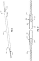
- Extension attachment 200 may be similar to identical to extension attachment 120 in many respects. Accordingly, particular attention will be directed to the features of extension attachment 200 that are different from extension attachment 120, with the understanding that these features may replace or be combined with the other features described herein.
- Extension attachment 200 as illustrated in Figures 9 and 10 includes a smoke evacuation shaft 202 that has a proximal end 204 and a distal end 206. Similar to proximal end 144 of smoke evacuation shaft 130, proximal end 204 may be inserted into a nozzle 148 on a hand piece 120.
- Smoke evacuation shaft 202 may be hollow or have flow channel therethrough to allow for smoke or fluid to pass therethrough. While smoke evacuation shaft 202 is illustrated with a substantially circular cross-sectional shape, it will be appreciated that smoke evacuation shaft 202 may have other cross-sectional shapes.
- Proximal end 204 of smoke evacuation shaft 202 includes two notches 208, 210. Notches 208, 210 on proximal end 204 of smoke evacuation shaft 202 are capable of receiving substrate 212. For example, as shown in Figure 10 , substrate 212 is cut to mate with notches 208, 210. Similarly, distal end 206 of smoke evacuation shaft 202 includes two notches 214, 216. Notches 214, 216 on proximal end 206 of smoke evacuation shaft 202 are capable of receiving blade 218. A quick set glue or other binding material may be used to secure the connection between notches 208, 210 and substrate 212 and between notches 214, 216 and blade 218.
- proximal end 204 of smoke evacuation shaft 202 and substrate 212 is illustrative only, and any suitable means of connecting substrate 212 and notches 208, 210 may be utilized.
- distal end 206 of smoke evacuation shaft 202 and blade 218 as shown in Figures 9 and 10 is illustrative only and any suitable means of connecting blade 218 and notches 214, 216 may be utilized.
- substrate 121 and blade 218 may be connected to proximal and distal ends 204, 206, respectively, without being inserted into notches.
- smoke evacuation shaft 202, substrate 212, and blade 218 may be integrally formed. For instance, stamping and rolling processes may be used to form extension attachment 200 from a single piece of material.
- Smoke evacuation shaft 202, substrate 212, and blade 218 may each be formed of a conductive material so as to be able to convey electrical current from a hand piece (e.g., hand piece 120) to a patient. More specifically, substrate 212 may include a mounting portion configured to connect to a collet (e.g., collet 140) and thereby receive electrical current for performing an electrical procedure. Because smoke evacuation shaft 202 is also formed of a conductive material, the electrical current received by substrate 212 may be conveyed to blade 218 by smoke evacuation shaft 202.
- a collet e.g., collet 140
- extension attachment 200 does not need an electrode tip and a separate smoke evacuation shaft to facilitate the performance of electrosurgical procedures and smoke capture. Rather, because smoke evacuation shaft 202 is formed of a conductive material, smoke evacuation shaft 202 functions both as a smoke evacuation shaft and part of the electrode that transmits electrical current to a patient.
Landscapes
- Health & Medical Sciences (AREA)
- Surgery (AREA)
- Life Sciences & Earth Sciences (AREA)
- Engineering & Computer Science (AREA)
- Veterinary Medicine (AREA)
- General Health & Medical Sciences (AREA)
- Nuclear Medicine, Radiotherapy & Molecular Imaging (AREA)
- Public Health (AREA)
- Biomedical Technology (AREA)
- Heart & Thoracic Surgery (AREA)
- Medical Informatics (AREA)
- Molecular Biology (AREA)
- Animal Behavior & Ethology (AREA)
- Otolaryngology (AREA)
- Plasma & Fusion (AREA)
- Physics & Mathematics (AREA)
- Neurology (AREA)
- Neurosurgery (AREA)
- Oral & Maxillofacial Surgery (AREA)
- Pathology (AREA)
- Surgical Instruments (AREA)
Claims (12)
- Verlängerungsaufsatz (200) zum Gebrauch mit einem Handteil, wobei der Verlängerungsaufsatz umfasst:einen ausgehöhlten Rauchabzugschaft (202) mit einem gegenüberliegenden ersten und zweiten Ende (204, 206) und einen Kanal, der sich dazwischen erstreckt, wobei das erste Ende zwei Einkerbungen (208, 210) aufweist und das zweite Ende zwei Einkerbungen (214, 216) aufweist, wobei der ausgehöhlte Rauchabzugschaft selektiv an ein elektrochirurgisches Instrument koppelbar ist, um Rauch von einer Operationsstelle durch den Kanal zum Handteil zu führen;ein Elektrodensubstrat (212), das am ersten Ende des ausgehöhlten Rauchabzugschafts angeordnet ist, wobei das Elektrodensubstrat von den beiden Einkerbungen am ersten Ende aufgenommen wird, wobei das Elektrodensubstrat dazu konfiguriert ist, sich mit einer Spannhülse im Handteil zu verbinden, so dass elektrischer Strom vom Handteil zum Elektrodensubstrat geführt werden kann; undeine Elektrodenklinge (218), die am zweiten Ende des ausgehöhlten Rauchabzugschafts angeordnet ist, wobei die Elektrodenklinge von den beiden Einkerbungen am zweiten Ende aufgenommen wird, wobei die Elektrodenklinge dazu konfiguriert ist, elektrischen Strom zum Gewebe eines Patienten zu führen.
- Rauchabzugaufsatz nach Anspruch 1, wobei der ausgehöhlte Rauchabzugschaft aus einem leitfähigen Material hergestellt ist, so dass der ausgehöhlte Rauchabzugschaft elektrischen Strom vom Elektrodensubstrat zur Elektrodenklinge führt.
- Rauchabzugaufsatz nach Anspruch 1, wobei der ausgehöhlte Rauchabzugschaft, die Elektrodenklinge und das Substrat einstückig ausgebildet sind.
- Verlängerungsaufsatz nach Anspruch 1, wobei die Elektrodenklinge vom zweiten Ende des Rauchabzugschafts vorsteht.
- Verlängerungsaufsatz nach Anspruch 1, wobei mindestens ein Abschnitt des Substrats vom ersten Ende des Rauchabzugschafts vorsteht.
- Verlängerungsaufsatz nach Anspruch 1, ferner umfassend eine Manschette, die mindestens um einen Abschnitt des Rauchabzugschafts angeordnet ist, wobei die Manschette dazu konfiguriert ist, eine Verbindung zwischen dem Rauchabzugschaft und einem Handteil abzudichten, wenn der Verlängerungsaufsatz mit dem Handteil gekoppelt ist.
- Verlängerungsaufsatz nach Anspruch 1, wobei sich der Rauchabzugschaft von einem ersten Durchmesser am zweiten Ende zu einem zweiten, kleineren Durchmesser am ersten Ende verjüngt.
- Verlängerungsaufsatz nach Anspruch 1, wobei der Rauchabzugschaft aus lichtdurchlässigen Materialien hergestellt ist.
- Verlängerungsaufsatz nach Anspruch 1, wobei die Klinge und das Substrat mit gegenüberliegenden Enden des Rauchabzugschafts verbunden sind.
- Verlängerungsaufsatz nach Anspruch 9, wobei der Rauchabzugschaft ein leitfähiges Material umfasst, so dass elektrischer Strom vom Substrat durch den Rauchabzugschaft und zur Klinge geführt wird.
- Verlängerungsaufsatz nach Anspruch 10, wobei der Rauchabzugschaft mit einem isolierenden Material beschichtet ist.
- Elektrochirurgisches Instrument, das dazu konfiguriert ist, elektrische Energie von einer elektrischen Energiequelle zum Gewebe eines Patienten zu übertragen und Rauch oder Fluid von einer Operationsstelle abzuführen, wobei das elektrochirurgische Instrument umfasst:ein Handteil, das dazu konfiguriert ist, von einem Benutzer gehalten zu werden, wobei das Handteil ein proximales Ende, ein distales Ende und einen Stutzen aufweist, wobei der Stutzen eine Öffnung umfasst, die dazu konfiguriert ist, einen Abschnitt einer Elektrodenspitze darin aufzunehmen und durch die Rauch abgezogen werden kann;den Verlängerungsaufsatz nach einem der vorhergehenden Ansprüche;ein Stromkabel zum Übertragen elektrischer Energie auf das Handteil; undeinen Rauchabzugschlauch in fluidischer Verbindung mit dem Rauchabzugschaft, wobei der Rauchabzugschlauch dazu konfiguriert ist, den in den Rauchabzugschaft gezogenen Rauch abzuführen.
Applications Claiming Priority (2)
| Application Number | Priority Date | Filing Date | Title |
|---|---|---|---|
| US15/596,257 US10765472B2 (en) | 2017-05-16 | 2017-05-16 | Electrosurgical instrument extension attachment |
| PCT/US2018/031718 WO2018213067A1 (en) | 2017-05-16 | 2018-05-09 | Electrosurgical instrument extension attachment |
Publications (2)
| Publication Number | Publication Date |
|---|---|
| EP3624720A1 EP3624720A1 (de) | 2020-03-25 |
| EP3624720B1 true EP3624720B1 (de) | 2021-06-23 |
Family
ID=62245472
Family Applications (1)
| Application Number | Title | Priority Date | Filing Date |
|---|---|---|---|
| EP18727550.8A Active EP3624720B1 (de) | 2017-05-16 | 2018-05-09 | Verlängerungsaufsatz für elektrochirurgisches instrument |
Country Status (11)
| Country | Link |
|---|---|
| US (1) | US10765472B2 (de) |
| EP (1) | EP3624720B1 (de) |
| JP (1) | JP7146813B2 (de) |
| KR (1) | KR20200008129A (de) |
| CN (1) | CN110636809B (de) |
| AU (1) | AU2018268973A1 (de) |
| BR (1) | BR112019023382A2 (de) |
| CA (1) | CA3061765A1 (de) |
| MX (1) | MX2019013742A (de) |
| TW (1) | TW201907877A (de) |
| WO (1) | WO2018213067A1 (de) |
Families Citing this family (7)
| Publication number | Priority date | Publication date | Assignee | Title |
|---|---|---|---|---|
| US12402931B2 (en) * | 2019-11-12 | 2025-09-02 | Stryker European Operations Limited | Electrosurgical device with illumination and smoke evacuation features |
| CN112914714A (zh) * | 2019-12-06 | 2021-06-08 | I.C.医疗股份有限公司 | 腹腔镜超极性电外科装置 |
| US12521166B2 (en) | 2020-06-15 | 2026-01-13 | Covidien Lp | Electrosurgical pencil with blowing and suction |
| EP4210611B1 (de) * | 2020-09-09 | 2025-09-17 | Stryker European Operations Limited | Elektrochirurgische vorrichtung |
| US12508067B2 (en) * | 2021-10-04 | 2025-12-30 | Covidien Lp | Smoke evacuation instrument with illumination nozzle |
| US12433667B2 (en) | 2022-04-12 | 2025-10-07 | Covidien Lp | Smoke evacuation electrosurgical pencil with lighting |
| CN116172709A (zh) * | 2022-11-21 | 2023-05-30 | 上海微创医疗机器人(集团)股份有限公司 | 可除烟的手术器械及手术机器人 |
Family Cites Families (84)
| Publication number | Priority date | Publication date | Assignee | Title |
|---|---|---|---|---|
| US5451223B1 (en) | 1983-03-14 | 1998-11-03 | Ben Simhon Haim | Electrosurgical instrument |
| US4683884A (en) | 1986-04-11 | 1987-08-04 | Md Engineering | Noise attenuating smokeless surgical device |
| US4936842A (en) | 1987-05-08 | 1990-06-26 | Circon Corporation | Electrosurgical probe apparatus |
| US5460602A (en) | 1989-01-23 | 1995-10-24 | Shapira; Nadiv | Smoke evacuator for smoke generating devices |
| US5192267A (en) | 1989-01-23 | 1993-03-09 | Nadiv Shapira | Vortex smoke remover for electrosurgical devices |
| US5244462A (en) | 1990-03-15 | 1993-09-14 | Valleylab Inc. | Electrosurgical apparatus |
| US5181916A (en) | 1991-04-26 | 1993-01-26 | Sorenson Laboratories, Inc. | Surgical probe and smoke eliminator |
| US5195959A (en) | 1991-05-31 | 1993-03-23 | Paul C. Smith | Electrosurgical device with suction and irrigation |
| US5662647A (en) | 1991-07-22 | 1997-09-02 | Transamerican Technologies International | Electrode assembly for electrosurgical instrument |
| US7297145B2 (en) | 1997-10-23 | 2007-11-20 | Arthrocare Corporation | Bipolar electrosurgical clamp for removing and modifying tissue |
| US6770071B2 (en) | 1995-06-07 | 2004-08-03 | Arthrocare Corporation | Bladed electrosurgical probe |
| US5318565A (en) | 1992-11-12 | 1994-06-07 | Daniel B. Kuriloff | Suction cautery dissector |
| US5431650A (en) | 1992-12-11 | 1995-07-11 | Cosmescu; Ioan | Vortex hand piece shroud for automatic smoke evacuator system for a surgical laser apparatus and method therefor |
| US5693044A (en) | 1992-12-11 | 1997-12-02 | Cosmescu; Ioan | Telescopic surgical device and method therefor |
| US5674219A (en) | 1994-10-06 | 1997-10-07 | Donaldson Company, Inc. | Electrosurgical smoke evacuator |
| US5830214A (en) | 1994-11-08 | 1998-11-03 | Heartport, Inc. | Fluid-evacuating electrosurgical device |
| US6063081A (en) | 1995-02-22 | 2000-05-16 | Medtronic, Inc. | Fluid-assisted electrocautery device |
| WO2003024506A2 (en) | 2001-09-14 | 2003-03-27 | Arthrocare Corporation | Methods and apparatus for treating intervertebral discs |
| US6837888B2 (en) | 1995-06-07 | 2005-01-04 | Arthrocare Corporation | Electrosurgical probe with movable return electrode and methods related thereto |
| US7393351B2 (en) | 1995-06-07 | 2008-07-01 | Arthrocare Corporation | Apparatus and methods for treating cervical inter-vertebral discs |
| US7270661B2 (en) | 1995-11-22 | 2007-09-18 | Arthocare Corporation | Electrosurgical apparatus and methods for treatment and removal of tissue |
| US6117134A (en) | 1996-02-14 | 2000-09-12 | Cunningham; James Steven | Instrument for suction electrosurgery |
| WO1998001075A1 (de) | 1996-07-04 | 1998-01-15 | Erbe Elektromedizin Gmbh | Gas unterstützte axial verschiebbare chirurgische elektrode |
| US5836909A (en) | 1996-09-13 | 1998-11-17 | Cosmescu; Ioan | Automatic fluid control system for use in open and laparoscopic laser surgery and electrosurgery and method therefor |
| US7112199B2 (en) | 1996-09-20 | 2006-09-26 | Ioan Cosmescu | Multifunctional telescopic monopolar/bipolar surgical device and method therefore |
| US6355034B2 (en) | 1996-09-20 | 2002-03-12 | Ioan Cosmescu | Multifunctional telescopic monopolar/bipolar surgical device and method therefor |
| US6706039B2 (en) | 1998-07-07 | 2004-03-16 | Medtronic, Inc. | Method and apparatus for creating a bi-polar virtual electrode used for the ablation of tissue |
| US7435247B2 (en) | 1998-08-11 | 2008-10-14 | Arthrocare Corporation | Systems and methods for electrosurgical tissue treatment |
| US7329253B2 (en) | 2003-12-09 | 2008-02-12 | Rubicor Medical, Inc. | Suction sleeve and interventional devices having such a suction sleeve |
| US6146353A (en) * | 1998-09-22 | 2000-11-14 | Sherwood Services Ag | Smoke extraction device |
| US6231571B1 (en) | 1999-05-03 | 2001-05-15 | Alan G. Ellman | Electrosurgical handpiece for treating tissue |
| US6379350B1 (en) | 1999-10-05 | 2002-04-30 | Oratec Interventions, Inc. | Surgical instrument for ablation and aspiration |
| CN2395704Y (zh) * | 1999-11-17 | 2000-09-13 | 王长喜 | 多功能吸引电刀 |
| US7041101B2 (en) | 1999-12-27 | 2006-05-09 | Neothermia Corporation | Electrosurgical accessing of tissue with controlled collateral thermal phenomena |
| US6293945B1 (en) | 2000-03-06 | 2001-09-25 | Everest Medical Corporation | Electrosurgical instrument with suction capability |
| US6530924B1 (en) | 2000-11-03 | 2003-03-11 | Alan G. Ellman | Electrosurgical tonsilar and adenoid electrode |
| US20020103485A1 (en) | 2000-12-05 | 2002-08-01 | Ivan Melnyk | Electrosurgical pencil with a smoke evacuating blade |
| US20020072739A1 (en) | 2000-12-07 | 2002-06-13 | Roberta Lee | Methods and devices for radiofrequency electrosurgery |
| US6921283B2 (en) | 2001-08-27 | 2005-07-26 | Trompeter Electronics, Inc. | BNC connector having visual indication |
| US6669695B2 (en) | 2002-01-15 | 2003-12-30 | Giancarlo Luigi | Multifunctional electrosurgical instrument |
| US20030181904A1 (en) * | 2002-01-23 | 2003-09-25 | Levine Andy H. | Electrosurgical cutting, coagulating and suction instrument |
| US7004939B2 (en) | 2002-09-03 | 2006-02-28 | Dale Victor Mackay | Electrosurgical apparatus |
| CN1233300C (zh) | 2003-02-19 | 2005-12-28 | 苏英 | 多功能手术解剖器 |
| US7120502B2 (en) * | 2003-02-21 | 2006-10-10 | Medtronic, Inc. | Shaft constructions for a medical device |
| US7331949B2 (en) * | 2003-02-27 | 2008-02-19 | Margaret Grahn Marisi | Urinary catheter with check valve |
| US7494473B2 (en) | 2003-07-30 | 2009-02-24 | Intact Medical Corp. | Electrical apparatus and system with improved tissue capture component |
| EP1902682B1 (de) | 2003-11-14 | 2017-01-11 | Lina Medical ApS | Längenverstellbarer elektrochirurgischer Stift mit Saugmitteln |
| US7241294B2 (en) | 2003-11-19 | 2007-07-10 | Sherwood Services Ag | Pistol grip electrosurgical pencil with manual aspirator/irrigator and methods of using the same |
| US7491200B2 (en) | 2004-03-26 | 2009-02-17 | Arthrocare Corporation | Method for treating obstructive sleep disorder includes removing tissue from base of tongue |
| US20060218752A1 (en) | 2005-03-30 | 2006-10-05 | Potempa Michael M | Collet locks and extension pole assemblies comprising same |
| US7500974B2 (en) | 2005-06-28 | 2009-03-10 | Covidien Ag | Electrode with rotatably deployable sheath |
| AU2006294745B2 (en) | 2005-09-27 | 2012-04-19 | Allegiance Corporation | Medical suction and irrigation device |
| US7947039B2 (en) | 2005-12-12 | 2011-05-24 | Covidien Ag | Laparoscopic apparatus for performing electrosurgical procedures |
| US20070265615A1 (en) | 2006-05-09 | 2007-11-15 | Haim Ben-Simhon | Electrosurgical instrument with suction, irrigation and means to collect blood |
| US8187272B2 (en) | 2006-10-06 | 2012-05-29 | Biomedcraft Designs, Inc. | Surgical instrument for coagulation and suction |
| US8057470B2 (en) | 2007-08-30 | 2011-11-15 | Conmed Corporation | Integrated smoke evacuation electrosurgical pencil and method |
| US20090069802A1 (en) | 2007-09-06 | 2009-03-12 | Garito Jon C | Electrosurgical electrode and method for use |
| WO2009070074A1 (en) * | 2007-11-29 | 2009-06-04 | St. Jude Medical Ab | Active fixation element |
| US8382753B2 (en) | 2008-10-21 | 2013-02-26 | Hermes Innovations, LLC | Tissue ablation methods |
| US8690872B2 (en) | 2008-11-14 | 2014-04-08 | Prash Jayaraj | Surgical pencil enabling suction |
| US8137345B2 (en) | 2009-01-05 | 2012-03-20 | Peak Surgical, Inc. | Electrosurgical devices for tonsillectomy and adenoidectomy |
| US8882768B2 (en) | 2009-04-24 | 2014-11-11 | Megadyne Medical Products, Inc. | Hand piece with adjustable utility conduit |
| US8882767B2 (en) | 2009-04-24 | 2014-11-11 | Megadyne Medical Products, Inc. | Electrosurgical instrument with adjustable utility conduit |
| US8323279B2 (en) | 2009-09-25 | 2012-12-04 | Arthocare Corporation | System, method and apparatus for electrosurgical instrument with movable fluid delivery sheath |
| US8317786B2 (en) | 2009-09-25 | 2012-11-27 | AthroCare Corporation | System, method and apparatus for electrosurgical instrument with movable suction sheath |
| US20110077645A1 (en) | 2009-09-29 | 2011-03-31 | San-Chih Yang Lin | Electrosurgical Pencil with Synchronous Evacuation Function |
| US9289261B2 (en) | 2010-02-04 | 2016-03-22 | Buffalo Filter Llc | Electrosurgical device with vacuum port |
| US8932286B2 (en) * | 2011-02-04 | 2015-01-13 | Nathan Andrew Terry | Apparatus and method for electrosurgical suction |
| US8518018B2 (en) | 2011-02-04 | 2013-08-27 | Noah Mark Minskoff | Apparatus and method for electrosurgical suction |
| US8932292B2 (en) | 2011-02-04 | 2015-01-13 | Integrated Surgical LLC | Apparatus and method for electrosurgical suction |
| US10595934B2 (en) * | 2011-05-02 | 2020-03-24 | I.C. Medical, Inc. | Electrosurgical unit pencil apparatus and shroud having directed illumination |
| WO2012154699A1 (en) | 2011-05-06 | 2012-11-15 | Ioan Cosmescu | Light attachment device for electrosurgical pencil and electrosurgical pencil attachments |
| CA2834591C (en) | 2011-05-19 | 2019-09-10 | Cimpax Aps | An electrosurgical pencil, a kit of parts comprising an electrosurgical pencil, and a method of providing an electrosurgical pencil |
| EP2559450A1 (de) * | 2011-08-19 | 2013-02-20 | Abbott Laboratories Vascular Enterprises Limited | Schaft für medizinische Vorrichtungen und Katheter |
| US8870864B2 (en) | 2011-10-28 | 2014-10-28 | Medtronic Advanced Energy Llc | Single instrument electrosurgery apparatus and its method of use |
| CN102512241A (zh) | 2011-11-11 | 2012-06-27 | 浙江舒友仪器设备有限公司 | 一种可换电极吸烟刀 |
| USD669581S1 (en) | 2011-12-22 | 2012-10-23 | Electromedical Associates, Llc | Electrosurgical cutting blade |
| US9456866B2 (en) * | 2012-08-10 | 2016-10-04 | William J. Zinnanti | Electrosurgery probes with smoke and liquid evacuation |
| US9101363B2 (en) * | 2012-08-10 | 2015-08-11 | William J. Zinnanti | Cautery electrode with multi-channel insulated shaft |
| US9375253B2 (en) * | 2013-03-14 | 2016-06-28 | Megadyne Medical Products, Inc. | Electrosurgical instrument |
| EP2792321B1 (de) | 2013-04-17 | 2017-02-15 | Vesalius Medical Technologies Bvba | Chirurgisches Instrument mit mehreren Kanülen |
| US10342609B2 (en) * | 2013-07-22 | 2019-07-09 | Boston Scientific Scimed, Inc. | Medical devices for renal nerve ablation |
| EP2862533B1 (de) * | 2013-10-18 | 2019-09-18 | Erbe Elektromedizin GmbH | Adapterelement, HF-Chirurgieinstrument, Adapteraufsatz und System |
| DE102013018160B3 (de) | 2013-12-05 | 2015-02-12 | Wieland Electric Gmbh | Elektrische Steckverbindung |
-
2017
- 2017-05-16 US US15/596,257 patent/US10765472B2/en active Active
-
2018
- 2018-05-09 KR KR1020197035423A patent/KR20200008129A/ko active Pending
- 2018-05-09 AU AU2018268973A patent/AU2018268973A1/en not_active Abandoned
- 2018-05-09 EP EP18727550.8A patent/EP3624720B1/de active Active
- 2018-05-09 JP JP2019563607A patent/JP7146813B2/ja active Active
- 2018-05-09 WO PCT/US2018/031718 patent/WO2018213067A1/en not_active Ceased
- 2018-05-09 MX MX2019013742A patent/MX2019013742A/es unknown
- 2018-05-09 CN CN201880032543.8A patent/CN110636809B/zh active Active
- 2018-05-09 CA CA3061765A patent/CA3061765A1/en not_active Abandoned
- 2018-05-09 BR BR112019023382-2A patent/BR112019023382A2/pt not_active Application Discontinuation
- 2018-05-15 TW TW107116431A patent/TW201907877A/zh unknown
Also Published As
| Publication number | Publication date |
|---|---|
| CN110636809A (zh) | 2019-12-31 |
| TW201907877A (zh) | 2019-03-01 |
| KR20200008129A (ko) | 2020-01-23 |
| JP2020520282A (ja) | 2020-07-09 |
| AU2018268973A1 (en) | 2019-11-07 |
| BR112019023382A2 (pt) | 2020-06-16 |
| WO2018213067A1 (en) | 2018-11-22 |
| US10765472B2 (en) | 2020-09-08 |
| JP7146813B2 (ja) | 2022-10-04 |
| CA3061765A1 (en) | 2018-11-22 |
| CN110636809B (zh) | 2023-05-05 |
| US20180333201A1 (en) | 2018-11-22 |
| EP3624720A1 (de) | 2020-03-25 |
| MX2019013742A (es) | 2020-01-15 |
Similar Documents
| Publication | Publication Date | Title |
|---|---|---|
| JP7146813B2 (ja) | 電気外科用器具の延長アタッチメント | |
| US6293945B1 (en) | Electrosurgical instrument with suction capability | |
| US7122035B2 (en) | Bipolar surgical forceps with argon plasma coagulation capability | |
| US6210410B1 (en) | Coagulation device for coagulating biological tissues | |
| CN110934637B (zh) | 具有可调节电极和通气管的排烟电外科手术笔 | |
| US8211103B2 (en) | Electrosurgical instrument with adjustable power cable | |
| US5084045A (en) | Suction surgical instrument | |
| US7549990B2 (en) | Surgical scissors with argon plasma coagulation capability | |
| CN105934214B (zh) | 用于将rf和/或微波能量传递到生物组织的电外科设备 | |
| JP3602794B2 (ja) | 多機能型入れ子式電気外科器具 | |
| US20030181904A1 (en) | Electrosurgical cutting, coagulating and suction instrument | |
| BR112020004123A2 (pt) | aparelho eletrocirúrgico | |
| JP2007527766A (ja) | 多機能伸縮な自在単極性/双極性外科用デバイスおよびそのための方法 | |
| US5360427A (en) | Retractable electro-suction device | |
| GB2452392A (en) | Method and electrosurgical pencil for electrode anchoring within an adjustable evacuation tube | |
| US12426946B2 (en) | Nasal coagulation suction device and methods | |
| US9795440B2 (en) | Single lumen cautery forceps | |
| EP3804650B1 (de) | Schnittstellenverbindung für elektrochirurgische vorrichtung | |
| CA2524529C (en) | Multifunctional electrosurgical instrument, and method therefor | |
| HK40020484A (en) | Electrosurgical instrument extension attachment | |
| HK40020484B (en) | Electrosurgical instrument extension attachment | |
| US12396781B2 (en) | Electrosurgical pencil integrating module and an electrosurgical device possessing module thereof | |
| CN222237800U (zh) | 高频电刀尖端保护装置及高频电刀 |
Legal Events
| Date | Code | Title | Description |
|---|---|---|---|
| STAA | Information on the status of an ep patent application or granted ep patent |
Free format text: STATUS: UNKNOWN |
|
| STAA | Information on the status of an ep patent application or granted ep patent |
Free format text: STATUS: THE INTERNATIONAL PUBLICATION HAS BEEN MADE |
|
| PUAI | Public reference made under article 153(3) epc to a published international application that has entered the european phase |
Free format text: ORIGINAL CODE: 0009012 |
|
| STAA | Information on the status of an ep patent application or granted ep patent |
Free format text: STATUS: REQUEST FOR EXAMINATION WAS MADE |
|
| 17P | Request for examination filed |
Effective date: 20191205 |
|
| AK | Designated contracting states |
Kind code of ref document: A1 Designated state(s): AL AT BE BG CH CY CZ DE DK EE ES FI FR GB GR HR HU IE IS IT LI LT LU LV MC MK MT NL NO PL PT RO RS SE SI SK SM TR |
|
| AX | Request for extension of the european patent |
Extension state: BA ME |
|
| DAV | Request for validation of the european patent (deleted) | ||
| DAX | Request for extension of the european patent (deleted) | ||
| GRAP | Despatch of communication of intention to grant a patent |
Free format text: ORIGINAL CODE: EPIDOSNIGR1 |
|
| STAA | Information on the status of an ep patent application or granted ep patent |
Free format text: STATUS: GRANT OF PATENT IS INTENDED |
|
| INTG | Intention to grant announced |
Effective date: 20210304 |
|
| GRAS | Grant fee paid |
Free format text: ORIGINAL CODE: EPIDOSNIGR3 |
|
| GRAA | (expected) grant |
Free format text: ORIGINAL CODE: 0009210 |
|
| STAA | Information on the status of an ep patent application or granted ep patent |
Free format text: STATUS: THE PATENT HAS BEEN GRANTED |
|
| AK | Designated contracting states |
Kind code of ref document: B1 Designated state(s): AL AT BE BG CH CY CZ DE DK EE ES FI FR GB GR HR HU IE IS IT LI LT LU LV MC MK MT NL NO PL PT RO RS SE SI SK SM TR |
|
| REG | Reference to a national code |
Ref country code: GB Ref legal event code: FG4D |
|
| REG | Reference to a national code |
Ref country code: CH Ref legal event code: EP |
|
| REG | Reference to a national code |
Ref country code: DE Ref legal event code: R096 Ref document number: 602018019016 Country of ref document: DE Ref country code: AT Ref legal event code: REF Ref document number: 1403613 Country of ref document: AT Kind code of ref document: T Effective date: 20210715 |
|
| REG | Reference to a national code |
Ref country code: IE Ref legal event code: FG4D |
|
| REG | Reference to a national code |
Ref country code: NL Ref legal event code: FP |
|
| REG | Reference to a national code |
Ref country code: LT Ref legal event code: MG9D |
|
| PG25 | Lapsed in a contracting state [announced via postgrant information from national office to epo] |
Ref country code: BG Free format text: LAPSE BECAUSE OF FAILURE TO SUBMIT A TRANSLATION OF THE DESCRIPTION OR TO PAY THE FEE WITHIN THE PRESCRIBED TIME-LIMIT Effective date: 20210923 Ref country code: LT Free format text: LAPSE BECAUSE OF FAILURE TO SUBMIT A TRANSLATION OF THE DESCRIPTION OR TO PAY THE FEE WITHIN THE PRESCRIBED TIME-LIMIT Effective date: 20210623 Ref country code: HR Free format text: LAPSE BECAUSE OF FAILURE TO SUBMIT A TRANSLATION OF THE DESCRIPTION OR TO PAY THE FEE WITHIN THE PRESCRIBED TIME-LIMIT Effective date: 20210623 Ref country code: FI Free format text: LAPSE BECAUSE OF FAILURE TO SUBMIT A TRANSLATION OF THE DESCRIPTION OR TO PAY THE FEE WITHIN THE PRESCRIBED TIME-LIMIT Effective date: 20210623 |
|
| REG | Reference to a national code |
Ref country code: AT Ref legal event code: MK05 Ref document number: 1403613 Country of ref document: AT Kind code of ref document: T Effective date: 20210623 |
|
| PG25 | Lapsed in a contracting state [announced via postgrant information from national office to epo] |
Ref country code: GR Free format text: LAPSE BECAUSE OF FAILURE TO SUBMIT A TRANSLATION OF THE DESCRIPTION OR TO PAY THE FEE WITHIN THE PRESCRIBED TIME-LIMIT Effective date: 20210924 Ref country code: LV Free format text: LAPSE BECAUSE OF FAILURE TO SUBMIT A TRANSLATION OF THE DESCRIPTION OR TO PAY THE FEE WITHIN THE PRESCRIBED TIME-LIMIT Effective date: 20210623 Ref country code: NO Free format text: LAPSE BECAUSE OF FAILURE TO SUBMIT A TRANSLATION OF THE DESCRIPTION OR TO PAY THE FEE WITHIN THE PRESCRIBED TIME-LIMIT Effective date: 20210923 Ref country code: SE Free format text: LAPSE BECAUSE OF FAILURE TO SUBMIT A TRANSLATION OF THE DESCRIPTION OR TO PAY THE FEE WITHIN THE PRESCRIBED TIME-LIMIT Effective date: 20210623 Ref country code: RS Free format text: LAPSE BECAUSE OF FAILURE TO SUBMIT A TRANSLATION OF THE DESCRIPTION OR TO PAY THE FEE WITHIN THE PRESCRIBED TIME-LIMIT Effective date: 20210623 |
|
| PG25 | Lapsed in a contracting state [announced via postgrant information from national office to epo] |
Ref country code: SK Free format text: LAPSE BECAUSE OF FAILURE TO SUBMIT A TRANSLATION OF THE DESCRIPTION OR TO PAY THE FEE WITHIN THE PRESCRIBED TIME-LIMIT Effective date: 20210623 Ref country code: EE Free format text: LAPSE BECAUSE OF FAILURE TO SUBMIT A TRANSLATION OF THE DESCRIPTION OR TO PAY THE FEE WITHIN THE PRESCRIBED TIME-LIMIT Effective date: 20210623 Ref country code: ES Free format text: LAPSE BECAUSE OF FAILURE TO SUBMIT A TRANSLATION OF THE DESCRIPTION OR TO PAY THE FEE WITHIN THE PRESCRIBED TIME-LIMIT Effective date: 20210623 Ref country code: SM Free format text: LAPSE BECAUSE OF FAILURE TO SUBMIT A TRANSLATION OF THE DESCRIPTION OR TO PAY THE FEE WITHIN THE PRESCRIBED TIME-LIMIT Effective date: 20210623 Ref country code: RO Free format text: LAPSE BECAUSE OF FAILURE TO SUBMIT A TRANSLATION OF THE DESCRIPTION OR TO PAY THE FEE WITHIN THE PRESCRIBED TIME-LIMIT Effective date: 20210623 Ref country code: PT Free format text: LAPSE BECAUSE OF FAILURE TO SUBMIT A TRANSLATION OF THE DESCRIPTION OR TO PAY THE FEE WITHIN THE PRESCRIBED TIME-LIMIT Effective date: 20211025 Ref country code: AT Free format text: LAPSE BECAUSE OF FAILURE TO SUBMIT A TRANSLATION OF THE DESCRIPTION OR TO PAY THE FEE WITHIN THE PRESCRIBED TIME-LIMIT Effective date: 20210623 Ref country code: CZ Free format text: LAPSE BECAUSE OF FAILURE TO SUBMIT A TRANSLATION OF THE DESCRIPTION OR TO PAY THE FEE WITHIN THE PRESCRIBED TIME-LIMIT Effective date: 20210623 |
|
| PG25 | Lapsed in a contracting state [announced via postgrant information from national office to epo] |
Ref country code: PL Free format text: LAPSE BECAUSE OF FAILURE TO SUBMIT A TRANSLATION OF THE DESCRIPTION OR TO PAY THE FEE WITHIN THE PRESCRIBED TIME-LIMIT Effective date: 20210623 |
|
| REG | Reference to a national code |
Ref country code: DE Ref legal event code: R097 Ref document number: 602018019016 Country of ref document: DE |
|
| PG25 | Lapsed in a contracting state [announced via postgrant information from national office to epo] |
Ref country code: DK Free format text: LAPSE BECAUSE OF FAILURE TO SUBMIT A TRANSLATION OF THE DESCRIPTION OR TO PAY THE FEE WITHIN THE PRESCRIBED TIME-LIMIT Effective date: 20210623 |
|
| PLBE | No opposition filed within time limit |
Free format text: ORIGINAL CODE: 0009261 |
|
| STAA | Information on the status of an ep patent application or granted ep patent |
Free format text: STATUS: NO OPPOSITION FILED WITHIN TIME LIMIT |
|
| 26N | No opposition filed |
Effective date: 20220324 |
|
| PG25 | Lapsed in a contracting state [announced via postgrant information from national office to epo] |
Ref country code: AL Free format text: LAPSE BECAUSE OF FAILURE TO SUBMIT A TRANSLATION OF THE DESCRIPTION OR TO PAY THE FEE WITHIN THE PRESCRIBED TIME-LIMIT Effective date: 20210623 |
|
| REG | Reference to a national code |
Ref country code: CH Ref legal event code: PL |
|
| REG | Reference to a national code |
Ref country code: BE Ref legal event code: MM Effective date: 20220531 |
|
| PG25 | Lapsed in a contracting state [announced via postgrant information from national office to epo] |
Ref country code: MC Free format text: LAPSE BECAUSE OF FAILURE TO SUBMIT A TRANSLATION OF THE DESCRIPTION OR TO PAY THE FEE WITHIN THE PRESCRIBED TIME-LIMIT Effective date: 20210623 Ref country code: LU Free format text: LAPSE BECAUSE OF NON-PAYMENT OF DUE FEES Effective date: 20220509 Ref country code: LI Free format text: LAPSE BECAUSE OF NON-PAYMENT OF DUE FEES Effective date: 20220531 Ref country code: CH Free format text: LAPSE BECAUSE OF NON-PAYMENT OF DUE FEES Effective date: 20220531 |
|
| PG25 | Lapsed in a contracting state [announced via postgrant information from national office to epo] |
Ref country code: IE Free format text: LAPSE BECAUSE OF NON-PAYMENT OF DUE FEES Effective date: 20220509 |
|
| PG25 | Lapsed in a contracting state [announced via postgrant information from national office to epo] |
Ref country code: BE Free format text: LAPSE BECAUSE OF NON-PAYMENT OF DUE FEES Effective date: 20220531 |
|
| PG25 | Lapsed in a contracting state [announced via postgrant information from national office to epo] |
Ref country code: MK Free format text: LAPSE BECAUSE OF FAILURE TO SUBMIT A TRANSLATION OF THE DESCRIPTION OR TO PAY THE FEE WITHIN THE PRESCRIBED TIME-LIMIT Effective date: 20210623 Ref country code: CY Free format text: LAPSE BECAUSE OF FAILURE TO SUBMIT A TRANSLATION OF THE DESCRIPTION OR TO PAY THE FEE WITHIN THE PRESCRIBED TIME-LIMIT Effective date: 20210623 |
|
| PG25 | Lapsed in a contracting state [announced via postgrant information from national office to epo] |
Ref country code: HU Free format text: LAPSE BECAUSE OF FAILURE TO SUBMIT A TRANSLATION OF THE DESCRIPTION OR TO PAY THE FEE WITHIN THE PRESCRIBED TIME-LIMIT; INVALID AB INITIO Effective date: 20180509 |
|
| PG25 | Lapsed in a contracting state [announced via postgrant information from national office to epo] |
Ref country code: TR Free format text: LAPSE BECAUSE OF FAILURE TO SUBMIT A TRANSLATION OF THE DESCRIPTION OR TO PAY THE FEE WITHIN THE PRESCRIBED TIME-LIMIT Effective date: 20210623 |
|
| PG25 | Lapsed in a contracting state [announced via postgrant information from national office to epo] |
Ref country code: MT Free format text: LAPSE BECAUSE OF FAILURE TO SUBMIT A TRANSLATION OF THE DESCRIPTION OR TO PAY THE FEE WITHIN THE PRESCRIBED TIME-LIMIT Effective date: 20210623 |
|
| PGFP | Annual fee paid to national office [announced via postgrant information from national office to epo] |
Ref country code: NL Payment date: 20250409 Year of fee payment: 8 |
|
| PGFP | Annual fee paid to national office [announced via postgrant information from national office to epo] |
Ref country code: DE Payment date: 20250402 Year of fee payment: 8 |
|
| PGFP | Annual fee paid to national office [announced via postgrant information from national office to epo] |
Ref country code: IT Payment date: 20250422 Year of fee payment: 8 |
|
| PGFP | Annual fee paid to national office [announced via postgrant information from national office to epo] |
Ref country code: FR Payment date: 20250401 Year of fee payment: 8 |
|
| PGFP | Annual fee paid to national office [announced via postgrant information from national office to epo] |
Ref country code: GB Payment date: 20260324 Year of fee payment: 9 |