EP3624726B1 - Alignement et orientation automatiques de paires d'arcades dentaires 3d numériques - Google Patents
Alignement et orientation automatiques de paires d'arcades dentaires 3d numériques Download PDFInfo
- Publication number
- EP3624726B1 EP3624726B1 EP18802265.1A EP18802265A EP3624726B1 EP 3624726 B1 EP3624726 B1 EP 3624726B1 EP 18802265 A EP18802265 A EP 18802265A EP 3624726 B1 EP3624726 B1 EP 3624726B1
- Authority
- EP
- European Patent Office
- Prior art keywords
- digital
- model
- arch
- mandible
- maxilla
- Prior art date
- Legal status (The legal status is an assumption and is not a legal conclusion. Google has not performed a legal analysis and makes no representation as to the accuracy of the status listed.)
- Active
Links
Images



Classifications
-
- A—HUMAN NECESSITIES
- A61—MEDICAL OR VETERINARY SCIENCE; HYGIENE
- A61C—DENTISTRY; APPARATUS OR METHODS FOR ORAL OR DENTAL HYGIENE
- A61C9/00—Impression cups, i.e. impression trays; Impression methods
- A61C9/004—Means or methods for taking digitized impressions
-
- A—HUMAN NECESSITIES
- A61—MEDICAL OR VETERINARY SCIENCE; HYGIENE
- A61C—DENTISTRY; APPARATUS OR METHODS FOR ORAL OR DENTAL HYGIENE
- A61C19/00—Dental auxiliary appliances
- A61C19/04—Measuring instruments specially adapted for dentistry
- A61C19/05—Measuring instruments specially adapted for dentistry for determining occlusion
-
- G—PHYSICS
- G06—COMPUTING OR CALCULATING; COUNTING
- G06T—IMAGE DATA PROCESSING OR GENERATION, IN GENERAL
- G06T19/00—Manipulating three-dimensional [3D] models or images for computer graphics
- G06T19/20—Editing of three-dimensional [3D] images, e.g. changing shapes or colours, aligning objects or positioning parts
-
- A—HUMAN NECESSITIES
- A61—MEDICAL OR VETERINARY SCIENCE; HYGIENE
- A61C—DENTISTRY; APPARATUS OR METHODS FOR ORAL OR DENTAL HYGIENE
- A61C5/00—Filling or capping teeth
-
- A—HUMAN NECESSITIES
- A61—MEDICAL OR VETERINARY SCIENCE; HYGIENE
- A61C—DENTISTRY; APPARATUS OR METHODS FOR ORAL OR DENTAL HYGIENE
- A61C7/00—Orthodontics, i.e. obtaining or maintaining the desired position of teeth, e.g. by straightening, evening, regulating, separating, or by correcting malocclusions
-
- G—PHYSICS
- G06—COMPUTING OR CALCULATING; COUNTING
- G06T—IMAGE DATA PROCESSING OR GENERATION, IN GENERAL
- G06T2210/00—Indexing scheme for image generation or computer graphics
- G06T2210/41—Medical
-
- G—PHYSICS
- G06—COMPUTING OR CALCULATING; COUNTING
- G06T—IMAGE DATA PROCESSING OR GENERATION, IN GENERAL
- G06T2219/00—Indexing scheme for manipulating 3D models or images for computer graphics
- G06T2219/20—Indexing scheme for editing of 3D models
- G06T2219/2016—Rotation, translation, scaling
Definitions
- intra-oral three-dimensional (3D) scanners are becoming increasingly widespread. These scanners produce digital 3D models which represent the 3D structure of a patient's dentition, including both hard and relevant soft tissues. These 3D scans are useful in many applications, most commonly for digital dental and orthodontic workflows such as in the creation of crowns, implants, and appliances.
- 3D scans are useful in many applications, most commonly for digital dental and orthodontic workflows such as in the creation of crowns, implants, and appliances.
- the digital 3D representations of the arches may not be placed in an orientation with respect to the desired viewpoint or even with respect to one another. Accordingly, a need exists to automatically detect and adjust those orientations of digital 3D dental arch pairs.
- US 2013/0066598 A1 discloses a computer-implemented method of using a dynamic virtual articulator for simulating occlusion of teeth, when performing computer-aided designing of one or more dental restorations for a patient, where the method comprises the steps of: providing the virtual articulator comprising a virtual three-dimensional model of the upper jaw and a virtual three-dimensional model of the lower jaw resembling the upper jaw and lower jaw, respectively, of the patient's mouth; providing movement of the virtual upper jaw and the virtual lower jaw relative to each other for simulating dynamic occlusion, whereby collisions between teeth in the virtual upper and virtual lower jaw occur; wherein the method further comprises: providing that the teeth in the virtual upper jaw and virtual lower jaw are blocked from penetrating each other's virtual surfaces in the collisions.
- US 2009/0316966 A1 discloses a method and an apparatus for combining 3D dental scans with other 3D data sets.
- a method for aligning dental arch pairs includes receiving a first digital 3D model of at least a portion of a person's mandible and a second a digital 3D model of at least a portion of the person's maxilla.
- First and second representative planes are estimated for the mandible and maxilla.
- the first and second digital 3D models are transformed such that the first and second representative planes are each aligned with their respective coordinate systems.
- the first and second digital 3D models are also transformed such that the mandible and the maxilla are each aligned with the same coordinate system.
- the first digital 3D model is brought into bite alignment with the second digital 3D model, after the transformations, such that the mandible is bite-aligned with the maxilla.
- the bite-aligned digital 3D models can also be transformed or rotated such that the mandible and maxilla are shown in a front view.
- Described herein are techniques for automatically aligning and orienting a pair of 3D dental arches, such as the mandible and maxilla scans (a person's upper and lower arches).
- the technique can result in arch pairs that are oriented so they point in a standard direction and are close to one another and mutually oriented in bite alignment shown in a horizontal front view.
- the techniques can also align and orient arch pairs in other directions and views.
- FIG. 1 is a diagram of a system 10 for receiving and processing digital 3D models based upon intra-oral 3D scans.
- System 10 includes a processor 20 receiving digital 3D models of teeth (12) from intra-oral 3D scans or scans of impressions of teeth.
- System 10 can also include an electronic display device 16, such as a liquid crystal display (LCD) device, and an input device 18 for receiving user commands or other information.
- LCD liquid crystal display
- System 10 can be implemented with, for example, a desktop, notebook, or tablet computer. System 10 can receive the 3D scans locally or remotely via a network.
- the 3D scans addressed herein are represented as triangular meshes.
- the triangular mesh is common representation of 3D surfaces and has two components.
- the first component referred to as the vertices of the mesh, are simply the coordinates of the 3D points that have been reconstructed on the surface - i.e., a point cloud.
- the second component the mesh faces, encodes the connections between points on the object and is an efficient way of interpolating between the discrete sample points on the continuous surface.
- Each face is a triangle defined by three vertices, resulting in a surface that can be represented as a set of small triangular planar patches.
- 3D scans of a patient's mandible and maxilla that have already been acquired.
- these scans are full-arch, meaning they include all the teeth in the arch; in other cases, they can be quadrant scans which include only 4-6 teeth.
- the scans of the two arches can be bite-aligned, meaning that the arches are positioned relative to one another in 3D space such that the teeth are in occlusion.
- the arches can be positioned in any arbitrary 3D position with respect to one another.
- the technique estimates 3D transformations, including rigid-body rotations and translations, that move the arches into positions in 3D space such that the following can occur: the arches are bite-aligned with one another so that the teeth are in at least approximate occlusion; the bite plane is horizontal, parallel to the X-Z plane; the arches are oriented in a standard direction, facing along the Z-axis; and the arches are centered about the origin.
- a bite-aligned arch pair can be shown in a side view, where the front of the bite-aligned arch pair faces the X-axis and a side of the pair faces the Z-axis from a viewer's perspective. Also, once the arch pair is bite-aligned, a viewer can optionally interact with the bite-aligned arch pair by rotating it to see a desired view.
- method 22 in the flow chart of FIG. 2 can be used to process a received case that includes digital 3D scans of a mandibular arch and a maxillary arch from the same person.
- Method 22 can be implemented in software or firmware modules, for example, for execution by processor 20, and can alternatively be implemented in hardware modules or a combination of software and hardware.
- Method 22 includes detecting if the scans, for example received scans 12, are full-arch or quadrant (step 24) and determining if the scans are bite-aligned (step 26). If the scans are already bite-aligned, then method 22 includes transforming (e.g., rotating) both arches such that the representative plane (e.g., occlusal plane) is horizontal (step 28), finding the in-plane rotation about the Y-axis that points the arches along the Z-axis (step 30), and centering the arches about the origin (step 42).
- the representative plane e.g., occlusal plane
- method 22 includes the following: transforming (e.g., rotating) the mandible such that its representative plane (e.g., occlusal plane) is horizontal (step 32); transforming (e.g., rotating) the maxilla such that its representative plane (e.g., occlusal plane) is horizontal (step 34); finding the transformation (e.g., rotation) about the Y-axis that points the mandible along the Z-axis (step 36); finding the transformation (e.g., rotation) about the Y-axis that points the maxilla along the Z-axis (step 38); bringing the two arches together into at least approximate bite alignment (step 40); and centering the arches about the origin (step 42).
- Transforming may include but is not limited to a rotation or a translation or a combination of both rotation and translation.
- steps 30, 36, and 38 are different depending upon whether the scans are full-arch or quadrant.
- an arch curve parameterization essentially a smooth one-dimensional (1D) curve that traverses the arch and follows the tops of the teeth.
- This curve can be determined by computing a 1D manifold embedding of the upper parts of the scans (i.e., the parts nearer to the occlusal surface) using techniques such as Locally Linear Embedding (LLE).
- LLE Locally Linear Embedding
- An example of an arch curve parameterization is shown in FIG. 3 with a 1D curve 44 overlaid on an image of an arch. The arrows emanating from the arch indicate its normal direction.
- the acquired 3D models can be either full-arch scans, covering all the teeth present in an arch, or quadrant scans, covering only 4-6 teeth. Examples of both types of scans are shown in FIG. 4 , illustrating a full-arch scan 46 and a quadrant scan 48.
- Whether a scan is full-arch or quadrant can be determined automatically by parameterizing the arch, as illustrated in FIG. 3 , and measuring the geodesic length of the curve, for example curve 44.
- Full-arch scans will result in longer arch curves than quadrant scans, and a suitable length threshold will differentiate between the two.
- a suitable threshold may be, for example, 70mm, where arch curves greater than the threshold are deemed a full-arch and arch curves equal to or less than the threshold are deemed a quadrant. Other thresholds can also be used.
- a pair of arch scans i.e., mandibular and maxillary arches
- bite alignment if they are close together in the directions normal (perpendicular) to their representative planes, and there is significant overlap between them when projected onto their representative planes.
- Being close together for bite alignment provides for the arch pairs being in occlusion, meaning in contact with one another, or within a particular distance from occlusion such as within 20mm, meaning the bite-aligned arch pairs are 20mm or less apart.
- Representative planes can be estimated using various techniques, for example the techniques described in the section entitled "Alignment Method 3 - Regression or Plane Fitting” in US Patent Application Publication No. 2016/0070821 , and specifically in Table 3 therein.
- the Support Vector Regression (SVR) approach has been found to robustly estimate the representative plane for a single arch, regardless of whether it is a quadrant of full-arch scan.
- Table 1 provides exemplary pseudocode for implementing this SVR approach to estimate representative planes.
- Output the normal vector perpendicular to representative plane which represents the desired upward direction of teeth. Assumptions: Teeth are roughly pointing up along the Y axis. The mesh has been truncated below the gum line. Method steps: 1 Subtract the mean of data points to centralize the data points around (0,0,0). 2 Apply the SVR with linear kernel and margin value ⁇ to find the representative plane. 3 Find the normal direction of the representative plane by geometrical methods or applying a simple PCA.
- FIG. 5 shows an example of a pair of arches 50 and 54, which are not bite-aligned, along with their estimated representative planes 52 and 56, respectively.
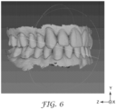
- An example of an arch pair that is bite-aligned is shown in FIG. 6 .
- the arch pair shown in FIG. 6 is also oriented for a desired view, in this case a front view where the arches are facing the Z-axis from a viewer's perspective and are essentially horizontal with respect to the X-Z plane.
- one criteria for deciding whether two arches are bite-aligned is based on the distances between the two representative planes of the arches in their normal directions. This can be computed according to the method in Table 2 (steps 2a, 2b, and 2c) for the mandibular arch.
- Table 2 Assuming that the mandible representative plane is given by n man T x + d man , and the maxilla representative plane is given by n max T x + d max , perform the method steps: 2a Compute the centroid of the mandible in (x,y,z), which is simply the mean of the 3D coordinates of all of its mesh vertices.
- x c [ x c y c z c ] T .
- 2b Compute the point on the mandible representative plane that is closest to the mandible centroid x c .
- x c ⁇ x c + ⁇ n man
- ⁇ ⁇ 1 n man T n man n man T x c + d man
- a second criteria for determining whether two arches are in bite alignment is based on how much overlap there is between the two arches when projected onto a plane. This is accomplished by first projecting both arches onto the representative plane of the smaller arch, and then measuring how much of the area occupied by one arch is occupied by the other arch in this two-dimensional (2D) projection. If the representative plane of the smaller arch is given by n and d , then a coordinate system is formed in which the Y-axis is a normal vector and the X- and Z-axes are orthogonal, and the vertices from both meshes are projected onto the X- and Z-axes, resulting in 2D coordinate for each point. This 2D space is quantized, and percentage of overlapping cells (occupied by both arches) is tabulated.
- both arches are rotated according to the representative plane of the mandibular arch. Otherwise, when the scans are not bite-aligned, each arch is rotated separately according to its own representative plane.
- the arches are rotated in-plane, about the Y-axis, so they are aligned in a standard orientation along the Z-axis.
- This rotation is estimated differently based on whether the scan is a full-arch or a quadrant scans, described below. In cases where the scans are not bite-aligned, this rotation about the Y-axis is estimated independently for each arch. Otherwise, when the scans are bite-aligned, the mean of the rotations estimated for the two arches is used.
- the arch curve parameterization described above results in a smooth 1D curve that traverses the arch, for example curve 44 illustrated in FIG. 3 .
- curve 44 illustrated in FIG. 3
- its mid-point can be estimated by finding the point along the curve at which half of its geodesic distance is on either side, for example point 45 on curve 44 in FIG. 3 .
- a goal in the case of a quadrant scan is to simply align the arch along the direction of the Z-axis as much as possible. This is accomplished by computing the first principal component of the vertices in 3D, using Principal Component Analysis (PCA), and then rotating the mesh so that this component is aligned with the Z-axis.
- PCA Principal Component Analysis
- the arches are brought into approximate alignment as follows. First the maxilla is shifted along the Y-axis so that its representative plane is a desired distance from that of the mandibular plane, for example the planes should be in at least approximate occlusion by being 20mm or less apart. Then, the maxilla is shifted in the X-Z plane such that its centroid is aligned with the centroid of the mandible.
- FIGS. 7 and 8 An example of an arch pair before and after being brought into approximate bite alignment is shown in FIGS. 7 and 8 , respectively.
- Another embodiment includes the following process. Automated bite alignment of arch pair scans can be achieved through a combination of 3D mesh processing and optimization. First, upper and lower arches are roughly aligned in the up-down direction (to be essentially parallel with the Z-axis), defined as the principle component with the smallest corresponding eigenvalue when PCA is applied to the mesh vertices. The arches are subsequently oriented so they are aligned in the X-Y plane.
- Another approach to anatomical landmarks is to use geometric features (e.g., spin image descriptors) around each vertex of the mesh. Then, the vertices of lower arch and upper arch with similar spin image descriptors are matched with each other, and a robust rigid-body transformation that aligns most of the matched vertices is estimated and applied to the upper arch.
- Arches are subsequently transformed in 3D in an iterative manner until all directed distances are positive and minimized.
- the 3D transformation can be determined using a constrained Iterative Closest Point (ICP) algorithm.
- ICP Iterative Closest Point
- This constrained/penalized ICP algorithm estimates a rigid-body transformation between two meshes where the negative directed distance between meshes is penalized more aggressively compared to the positive directed distance, or vice versa.
- This other embodiment can be used to present the bite-aligned arches with teeth in occlusion.
Landscapes
- Health & Medical Sciences (AREA)
- Engineering & Computer Science (AREA)
- Life Sciences & Earth Sciences (AREA)
- Public Health (AREA)
- Veterinary Medicine (AREA)
- Oral & Maxillofacial Surgery (AREA)
- Dentistry (AREA)
- Epidemiology (AREA)
- Animal Behavior & Ethology (AREA)
- General Health & Medical Sciences (AREA)
- Architecture (AREA)
- Computer Graphics (AREA)
- Computer Hardware Design (AREA)
- General Engineering & Computer Science (AREA)
- Software Systems (AREA)
- Physics & Mathematics (AREA)
- General Physics & Mathematics (AREA)
- Theoretical Computer Science (AREA)
- Biomedical Technology (AREA)
- Biophysics (AREA)
- Dental Tools And Instruments Or Auxiliary Dental Instruments (AREA)
- Apparatus For Radiation Diagnosis (AREA)
- Processing Or Creating Images (AREA)
Claims (15)
- Procédé pour l'alignement de paires d'arcade dentaire (50, 54), le procédé étant mis en oeuvre par un processeur (20) et comprenant des étapes consistant à :recevoir un premier modèle 3D numérique d'au moins une partie de la mandibule d'une personne et un second modèle 3D numérique d'au moins une partie du maxillaire de la personne ;estimer un premier plan représentatif (56) dans le premier modèle 3D numérique pour la mandibule et un second plan représentatif (52) dans le second modèle 3D numérique pour le maxillaire ;une première étape de transformation consistant à transformer le premier modèle 3D numérique et le second modèle 3D numérique de telle sorte que le premier plan représentatif (56) et le second plan représentatif (52) sont chacun alignés avec des systèmes de coordonnées respectifs ;une seconde étape de transformation consistant à transformer le premier modèle 3D numérique et le second modèle 3D numérique de telle sorte que la mandibule et le maxillaire dans les modèles 3D numériques sont chacun alignés avec un même système de coordonnées ; etentraîner le premier modèle 3D numérique en alignement d'occlusion avec le second modèle 3D numérique, après les étapes de transformation, de telle sorte que la mandibule est alignée en occlusion avec le maxillaire dans les modèles 3D numériques,dans lequel le procédé comprend en outre la détection à savoir si le premier modèle 3D numérique représente une arcade complète ou une arcade à quadrants de la mandibule et si le second modèle 3D numérique représente une arcade complète ou une arcade à quadrants du maxillaire, et dans lequel la seconde étape de transformation comprend une rotation différente dans le plan en fonction de si le premier modèle 3D numérique représente une arcade complète ou une arcade à quadrants de la mandibule et de si le second modèle 3D numérique représente une arcade complète ou une arcade à quadrants du maxillaire.
- Procédé selon la revendication 1, comprenant en outre la transformation des premier et second modèles 3D numériques de telle sorte que la mandibule et le maxillaire alignés en occlusion sont orientés dans une vue de face.
- Procédé selon la revendication 1, dans lequel la première étape de transformation comprend la transformation des premier et second modèles 3D numériques de telle sorte que les premier et second plans représentatifs sont horizontaux du point de vue d'un observateur.
- Procédé selon la revendication 1, dans lequel l'étape de détection comprend :la superposition d'une première courbe (44) sur le premier modèle 3D numérique qui traverse la mandibule et la détermination à savoir si la longueur de la première courbe est supérieure à un seuil ; etla superposition d'une seconde courbe sur le second modèle 3D numérique qui traverse le maxillaire et la détermination à savoir si la longueur de la seconde courbe est supérieure au seuil.
- Procédé selon la revendication 1, dans lequel la seconde étape de transformation comprend une rotation dans le plan autour d'un axe et la rotation est estimée différemment en fonction de si le premier modèle 3D numérique représente une arcade complète ou une arcade à quadrants de la mandibule et de si le second modèle 3D numérique représente une arcade complète ou une arcade à quadrants du maxillaire.
- Procédé selon la revendication 1, dans lequel l'étape d'entraînement comprend :un premier décalage du second modèle 3D numérique tel que le second plan représentatif est à une distance particulière du premier plan représentatif ; etun second décalage du premier modèle 3D numérique de telle sorte qu'un centroïde de la mandibule est aligné avec un centroïde du maxillaire dans les modèles 3D numériques.
- Procédé selon la revendication 6, dans lequel la première étape de décalage comprend le décalage du second modèle 3D numérique tel que le second plan représentatif est à moins de 20 mm du premier plan représentatif.
- Procédé selon la revendication 1, dans lequel l'étape d'entraînement comprend la transformation des premier et second modèles 3D numériques d'une manière itérative jusqu'à ce que des distances dirigées entre la mandibule et le maxillaire dans les modèles 3D numériques soient positives et minimisées.
- Système (10) pour l'alignement de paires d'arcade dentaire (50, 54), le système comprenant :un module pour la réception d'un premier modèle 3D numérique d'au moins une partie de la mandibule d'une personne et d'un second modèle 3D numérique d'au moins une partie du maxillaire de la personne ;un module pour l'estimation d'un premier plan représentatif (56) dans le premier modèle 3D numérique pour la mandibule et d'un second plan représentatif (52) dans le second modèle 3D numérique pour le maxillaire ;un module pour la mise en oeuvre d'une première transformation du premier modèle 3D numérique et du second modèle 3D numérique de telle sorte que le premier plan représentatif (56) et le second plan représentatif (52) sont chacun alignés avec des systèmes de coordonnées respectifs ;un module pour la mise en oeuvre d'une seconde transformation consistant à transformer le premier modèle 3D numérique et le second modèle 3D numérique de telle sorte que la mandibule et le maxillaire dans les modèles 3D numériques sont chacun alignés avec un même système de coordonnées ; etun module pour l'entraînement du premier modèle 3D numérique en alignement d'occlusion avec le second modèle 3D numérique, après la transformation, de telle sorte que la mandibule est alignée en occlusion avec le maxillaire dans les modèles 3D numériques,dans lequel le système (10) comprend en outre un module pour la détection à savoir si le premier modèle 3D numérique représente une arcade complète ou une arcade à quadrants de la mandibule et si le second modèle 3D numérique représente une arcade complète ou une arcade à quadrants du maxillaire, etdans lequel le système (10) est opérationnel pour mettre en oeuvre la seconde transformation au moyen d'une rotation différente dans le plan en fonction de si le premier modèle 3D numérique représente une arcade complète ou une arcade à quadrants de la mandibule et de si le second modèle 3D numérique représente une arcade complète ou une arcade à quadrants du maxillaire.
- Système (10) selon la revendication 9, comprenant en outre un module pour la transformation des premier et second modèles 3D numériques de telle sorte que la mandibule et le maxillaire alignés en occlusion sont orientés dans une vue de face.
- Système (10) selon la revendication 9, dans lequel le premier module de transformation comprend un module pour la transformation des premier et second modèles 3D numériques de telle sorte que les premier et second plans représentatifs sont horizontaux du point de vue d'un observateur.
- Système (10) selon la revendication 9, dans lequel le module pour la mise en oeuvre de la seconde transformation est opérationnel pour mettre en oeuvre une rotation dans le plan autour d'un axe et pour estimer la rotation différemment en fonction de si le premier modèle 3D numérique représente une arcade complète ou une arcade à quadrants de la mandibule et de si le second modèle 3D numérique représente une arcade complète ou une arcade à quadrants du maxillaire.
- Système (10) selon la revendication 9, dans lequel le module d'entraînement comprend :un module pour le premier décalage du second modèle 3D numérique tel que le second plan représentatif est à une distance particulière du premier plan représentatif ; etun module pour le second décalage du premier modèle 3D numérique de telle sorte qu'un centroïde de la mandibule est aligné avec un centroïde du maxillaire dans les modèles 3D numériques.
- Système (10) selon la revendication 13, dans lequel le premier module de décalage comprend un module pour le décalage du second modèle 3D numérique tel que le second plan représentatif est à moins de 20 mm du premier plan représentatif.
- Système (10) selon la revendication 9, dans lequel le module d'entraînement comprend un module pour la transformation des premier et second modèles 3D numériques d'une manière itérative jusqu'à ce que des distances dirigées entre la mandibule et le maxillaire dans les modèles 3D numériques soient positives et minimisées.
Applications Claiming Priority (2)
| Application Number | Priority Date | Filing Date | Title |
|---|---|---|---|
| US15/597,479 US10492892B2 (en) | 2017-05-17 | 2017-05-17 | Automatic alignment and orientation of digital 3D dental arch pairs |
| PCT/IB2018/053228 WO2018211361A1 (fr) | 2017-05-17 | 2018-05-09 | Alignement et orientation automatiques de paires d'arcades dentaires 3d numériques |
Publications (3)
| Publication Number | Publication Date |
|---|---|
| EP3624726A1 EP3624726A1 (fr) | 2020-03-25 |
| EP3624726A4 EP3624726A4 (fr) | 2021-01-06 |
| EP3624726B1 true EP3624726B1 (fr) | 2023-10-04 |
Family
ID=64269769
Family Applications (1)
| Application Number | Title | Priority Date | Filing Date |
|---|---|---|---|
| EP18802265.1A Active EP3624726B1 (fr) | 2017-05-17 | 2018-05-09 | Alignement et orientation automatiques de paires d'arcades dentaires 3d numériques |
Country Status (6)
| Country | Link |
|---|---|
| US (1) | US10492892B2 (fr) |
| EP (1) | EP3624726B1 (fr) |
| JP (1) | JP7773296B2 (fr) |
| CN (1) | CN110678145B (fr) |
| AU (1) | AU2018268194B2 (fr) |
| WO (1) | WO2018211361A1 (fr) |
Families Citing this family (26)
| Publication number | Priority date | Publication date | Assignee | Title |
|---|---|---|---|---|
| US10803675B2 (en) * | 2018-02-20 | 2020-10-13 | Ivoclar Vivadent Ag | Dental model attributes transfer |
| US10315353B1 (en) | 2018-11-13 | 2019-06-11 | SmileDirectClub LLC | Systems and methods for thermoforming dental aligners |
| EP3675036A1 (fr) * | 2018-12-28 | 2020-07-01 | Trophy | Segmentation 3d pour mandibule et maxillaire |
| US11007042B2 (en) | 2019-02-06 | 2021-05-18 | Sdc U.S. Smilepay Spv | Systems and methods for marking models for dental aligner fabrication |
| US10482192B1 (en) | 2019-02-12 | 2019-11-19 | SmileDirectClub LLC | Systems and methods for selecting and marking a location on a dental aligner |
| CN114144841B (zh) * | 2019-07-18 | 2026-01-06 | 舒万诺知识产权公司 | 用于牙科处理的虚拟关节运动模型 |
| US11612451B2 (en) | 2020-02-06 | 2023-03-28 | Patrick C. Bell | Dental scanning methods for analyzing jaws |
| US12186154B2 (en) | 2020-02-06 | 2025-01-07 | Patrick C. Bell | Dental methods with fiducial marker transfer jigs |
| US12307656B2 (en) | 2020-02-06 | 2025-05-20 | Patrick C. Bell | Computer assisted dental methods for analyzing jaws |
| US11963829B2 (en) | 2020-02-06 | 2024-04-23 | Patrick C. Bell | Fiducial markers for analyzing human jaws |
| WO2021158331A1 (fr) * | 2020-02-06 | 2021-08-12 | Bell Patrick C | Procédés de balayage dentaire pour l'analyse de mâchoires |
| KR102331034B1 (ko) * | 2020-12-10 | 2021-12-01 | 이마고웍스 주식회사 | 치과용 3차원 스캔 데이터의 랜드마크 자동 검출 방법 및 이를 컴퓨터에서 실행시키기 위한 프로그램이 기록된 컴퓨터로 읽을 수 있는 기록 매체 |
| KR102446421B1 (ko) * | 2020-06-05 | 2022-09-23 | 오스템임플란트 주식회사 | 스캔 데이터를 제공하는 디바이스 및 방법 |
| CN112185509B (zh) * | 2020-08-13 | 2024-03-29 | 上海埃蒙迪材料科技股份有限公司 | 一种参数化排牙的方法 |
| US11744530B2 (en) | 2020-09-15 | 2023-09-05 | Patrick C. Bell | Radiographic dental jigs and associated methods |
| WO2022085090A1 (fr) * | 2020-10-20 | 2022-04-28 | 富士通株式会社 | Programme d'alignement, procédé d'alignement et dispositif de traitement d'informations |
| CN112562084B (zh) * | 2020-12-21 | 2024-05-07 | 成都玻尔兹曼智贝科技有限公司 | 一种提取牙齿三维点云模型牙弓曲线的方法及系统 |
| US11116606B1 (en) | 2021-01-06 | 2021-09-14 | Arkimos Ltd. | Systems and methods for determining a jaw curve |
| US11364103B1 (en) | 2021-05-13 | 2022-06-21 | Oxilio Ltd | Systems and methods for determining a bite position between teeth of a subject |
| US11191619B1 (en) * | 2021-05-13 | 2021-12-07 | Oxilio Ltd | Methods and systems for determining occlusal contacts between teeth of a subject |
| US11759296B2 (en) * | 2021-08-03 | 2023-09-19 | Ningbo Shenlai Medical Technology Co., Ltd. | Method for generating a digital data set representing a target tooth arrangement |
| CN116071443A (zh) * | 2021-10-29 | 2023-05-05 | 正雅齿科科技(上海)有限公司 | 牙颌咬合深度展示方法、图形处理器及电子设备 |
| US11833759B1 (en) * | 2022-09-13 | 2023-12-05 | Oxilio Ltd | Systems and methods for making an orthodontic appliance |
| CN115965771B (zh) * | 2023-03-16 | 2023-05-16 | 信艺(广州)义齿研制有限公司 | 一种基于非人体自然牙色的假牙修复体的检测筛选方法 |
| US20240374347A1 (en) * | 2023-05-12 | 2024-11-14 | Exocad Gmbh | Correcting relative tooth positions of antagonistic teeth |
| EP4553764A1 (fr) * | 2023-11-10 | 2025-05-14 | Digicuto | Méthode mise en oeuvre par ordinateur et système cad pour centrer et aligner automatiquement un maillage 3d d'une mâchoire dans un système cad |
Family Cites Families (25)
| Publication number | Priority date | Publication date | Assignee | Title |
|---|---|---|---|---|
| US6227850B1 (en) * | 1999-05-13 | 2001-05-08 | Align Technology, Inc. | Teeth viewing system |
| US7068825B2 (en) * | 1999-03-08 | 2006-06-27 | Orametrix, Inc. | Scanning system and calibration method for capturing precise three-dimensional information of objects |
| US7160110B2 (en) | 1999-11-30 | 2007-01-09 | Orametrix, Inc. | Three-dimensional occlusal and interproximal contact detection and display using virtual tooth models |
| US7471821B2 (en) * | 2000-04-28 | 2008-12-30 | Orametrix, Inc. | Method and apparatus for registering a known digital object to scanned 3-D model |
| US7027642B2 (en) * | 2000-04-28 | 2006-04-11 | Orametrix, Inc. | Methods for registration of three-dimensional frames to create three-dimensional virtual models of objects |
| US7040896B2 (en) | 2000-08-16 | 2006-05-09 | Align Technology, Inc. | Systems and methods for removing gingiva from computer tooth models |
| US7736147B2 (en) * | 2000-10-30 | 2010-06-15 | Align Technology, Inc. | Systems and methods for bite-setting teeth models |
| US8021147B2 (en) * | 2001-04-13 | 2011-09-20 | Orametrix, Inc. | Method and system for comprehensive evaluation of orthodontic care using unified workstation |
| US9421074B2 (en) * | 2001-04-13 | 2016-08-23 | Orametrix, Inc. | Unified three dimensional virtual craniofacial and dentition model and uses thereof |
| US7077647B2 (en) | 2002-08-22 | 2006-07-18 | Align Technology, Inc. | Systems and methods for treatment analysis by teeth matching |
| US7695278B2 (en) | 2005-05-20 | 2010-04-13 | Orametrix, Inc. | Method and system for finding tooth features on a virtual three-dimensional model |
| US7118375B2 (en) * | 2004-01-08 | 2006-10-10 | Duane Milford Durbin | Method and system for dental model occlusal determination using a replicate bite registration impression |
| US7605817B2 (en) | 2005-11-09 | 2009-10-20 | 3M Innovative Properties Company | Determining camera motion |
| US8275180B2 (en) | 2007-08-02 | 2012-09-25 | Align Technology, Inc. | Mapping abnormal dental references |
| US8075306B2 (en) | 2007-06-08 | 2011-12-13 | Align Technology, Inc. | System and method for detecting deviations during the course of an orthodontic treatment to gradually reposition teeth |
| EP2280651A2 (fr) * | 2008-05-16 | 2011-02-09 | Geodigm Corporation | Procédé et appareil permettant de combiner des images de scanner dentaire 3d avec d'autres ensembles de données 3d |
| JP5859986B2 (ja) * | 2010-02-25 | 2016-02-16 | 3シェイプ アー/エス | 動的仮想咬合器 |
| US8244028B2 (en) | 2010-04-30 | 2012-08-14 | Align Technology, Inc. | Virtual cephalometric imaging |
| EP3777756B1 (fr) * | 2012-02-14 | 2025-04-09 | 3Shape A/S | Modélisation d'une conception numérique d'une prothèse dentaire |
| CN103908352B (zh) * | 2013-01-07 | 2016-08-10 | 无锡时代天使医疗器械科技有限公司 | 用于生成数字虚拟颌架的方法和系统 |
| CN105007856B (zh) * | 2013-03-11 | 2018-08-03 | 卡尔斯特里姆保健公司 | 用于咬合配准的方法和系统 |
| CN104715099B (zh) * | 2013-12-17 | 2018-03-30 | 北京大学口腔医学院 | 用于牙齿冠桥功能性咬合面的虚拟牙合架设计方法 |
| US10980618B2 (en) * | 2014-05-08 | 2021-04-20 | Cagenix, Inc. | Dental framework and prosthesis |
| US10192003B2 (en) | 2014-09-08 | 2019-01-29 | 3M Innovative Properties Company | Method of aligning intra-oral digital 3D models |
| KR20180006917A (ko) * | 2015-05-15 | 2018-01-19 | 트로피 | 교합 치아 모형의 x선 스캔을 위한 방법 및 장치 |
-
2017
- 2017-05-17 US US15/597,479 patent/US10492892B2/en active Active
-
2018
- 2018-05-09 WO PCT/IB2018/053228 patent/WO2018211361A1/fr not_active Ceased
- 2018-05-09 JP JP2019563425A patent/JP7773296B2/ja active Active
- 2018-05-09 AU AU2018268194A patent/AU2018268194B2/en active Active
- 2018-05-09 EP EP18802265.1A patent/EP3624726B1/fr active Active
- 2018-05-09 CN CN201880032569.2A patent/CN110678145B/zh active Active
Also Published As
| Publication number | Publication date |
|---|---|
| AU2018268194A1 (en) | 2019-12-05 |
| CN110678145B (zh) | 2022-04-01 |
| EP3624726A4 (fr) | 2021-01-06 |
| CN110678145A (zh) | 2020-01-10 |
| US10492892B2 (en) | 2019-12-03 |
| JP7773296B2 (ja) | 2025-11-19 |
| EP3624726A1 (fr) | 2020-03-25 |
| US20180333231A1 (en) | 2018-11-22 |
| AU2018268194B2 (en) | 2021-02-04 |
| JP2020520269A (ja) | 2020-07-09 |
| WO2018211361A1 (fr) | 2018-11-22 |
Similar Documents
| Publication | Publication Date | Title |
|---|---|---|
| EP3624726B1 (fr) | Alignement et orientation automatiques de paires d'arcades dentaires 3d numériques | |
| JP7245809B2 (ja) | 口腔内デジタル三次元モデルを位置合わせする方法 | |
| US12016745B2 (en) | Methods and systems of digital dental modeling | |
| EP3354229B1 (fr) | Procédé d'identification d'un état occlusal, appareil d'identification d'un état occlusal | |
| CN103443827B (zh) | 用于提供面部调节图像的方法和系统 | |
| CN105447908B (zh) | 基于口腔扫描数据和cbct数据的牙列模型生成方法 | |
| EP3349680B1 (fr) | Procédé de création de modèle d'arcade flexible de dents destiné à être utilisé en médecine dentaire restauratrice | |
| KR102035327B1 (ko) | 이동 회전 정보 생성 컴퓨터 프로그램, 이동 회전 정보 생성 장치 및 그 방법 | |
| US20190295250A1 (en) | Method, apparatus and system for reconstructing images of 3d surface | |
| CN101216953A (zh) | 颅骨三维模型构建方法 | |
| KR20180006917A (ko) | 교합 치아 모형의 x선 스캔을 위한 방법 및 장치 | |
| US7824346B2 (en) | Determining condyle displacement utilizing electronic models of dental impressions having a common coordinate system | |
| Wirtz et al. | Automatic model-based 3-D reconstruction of the teeth from five photographs with predefined viewing directions | |
| US20160005237A1 (en) | Method and system for automatically aligning models of an upper jaw and a lower jaw | |
| TWI679969B (zh) | 咬合壓力解析裝置、咬合壓力解析程式、及咬合壓力解析方法 | |
| CN118887079A (zh) | 患者外貌照形变方法 |
Legal Events
| Date | Code | Title | Description |
|---|---|---|---|
| STAA | Information on the status of an ep patent application or granted ep patent |
Free format text: STATUS: THE INTERNATIONAL PUBLICATION HAS BEEN MADE |
|
| PUAI | Public reference made under article 153(3) epc to a published international application that has entered the european phase |
Free format text: ORIGINAL CODE: 0009012 |
|
| STAA | Information on the status of an ep patent application or granted ep patent |
Free format text: STATUS: REQUEST FOR EXAMINATION WAS MADE |
|
| 17P | Request for examination filed |
Effective date: 20191119 |
|
| AK | Designated contracting states |
Kind code of ref document: A1 Designated state(s): AL AT BE BG CH CY CZ DE DK EE ES FI FR GB GR HR HU IE IS IT LI LT LU LV MC MK MT NL NO PL PT RO RS SE SI SK SM TR |
|
| AX | Request for extension of the european patent |
Extension state: BA ME |
|
| DAV | Request for validation of the european patent (deleted) | ||
| DAX | Request for extension of the european patent (deleted) | ||
| A4 | Supplementary search report drawn up and despatched |
Effective date: 20201209 |
|
| RIC1 | Information provided on ipc code assigned before grant |
Ipc: A61B 6/14 20060101ALI20201203BHEP Ipc: A61C 7/00 20060101AFI20201203BHEP Ipc: A61C 9/00 20060101ALI20201203BHEP Ipc: A61C 19/05 20060101ALI20201203BHEP |
|
| STAA | Information on the status of an ep patent application or granted ep patent |
Free format text: STATUS: EXAMINATION IS IN PROGRESS |
|
| 17Q | First examination report despatched |
Effective date: 20220614 |
|
| GRAP | Despatch of communication of intention to grant a patent |
Free format text: ORIGINAL CODE: EPIDOSNIGR1 |
|
| STAA | Information on the status of an ep patent application or granted ep patent |
Free format text: STATUS: GRANT OF PATENT IS INTENDED |
|
| INTG | Intention to grant announced |
Effective date: 20230426 |
|
| GRAS | Grant fee paid |
Free format text: ORIGINAL CODE: EPIDOSNIGR3 |
|
| GRAA | (expected) grant |
Free format text: ORIGINAL CODE: 0009210 |
|
| STAA | Information on the status of an ep patent application or granted ep patent |
Free format text: STATUS: THE PATENT HAS BEEN GRANTED |
|
| AK | Designated contracting states |
Kind code of ref document: B1 Designated state(s): AL AT BE BG CH CY CZ DE DK EE ES FI FR GB GR HR HU IE IS IT LI LT LU LV MC MK MT NL NO PL PT RO RS SE SI SK SM TR |
|
| REG | Reference to a national code |
Ref country code: GB Ref legal event code: FG4D |
|
| REG | Reference to a national code |
Ref country code: CH Ref legal event code: EP |
|
| REG | Reference to a national code |
Ref country code: DE Ref legal event code: R096 Ref document number: 602018058770 Country of ref document: DE |
|
| REG | Reference to a national code |
Ref country code: IE Ref legal event code: FG4D |
|
| REG | Reference to a national code |
Ref country code: LT Ref legal event code: MG9D |
|
| REG | Reference to a national code |
Ref country code: NL Ref legal event code: MP Effective date: 20231004 |
|
| RAP2 | Party data changed (patent owner data changed or rights of a patent transferred) |
Owner name: SOLVENTUM INTELLECTUAL PROPERTIES COMPANY |
|
| REG | Reference to a national code |
Ref country code: AT Ref legal event code: MK05 Ref document number: 1616929 Country of ref document: AT Kind code of ref document: T Effective date: 20231004 |
|
| REG | Reference to a national code |
Ref country code: DE Ref legal event code: R081 Ref document number: 602018058770 Country of ref document: DE Owner name: SOLVENTUM INTELLECTUAL PROPERTIES CO. (N.D.GES, US Free format text: FORMER OWNER: 3M INNOVATIVE PROPERTIES COMPANY, SAINT PAUL, MN, US |
|
| PG25 | Lapsed in a contracting state [announced via postgrant information from national office to epo] |
Ref country code: NL Free format text: LAPSE BECAUSE OF FAILURE TO SUBMIT A TRANSLATION OF THE DESCRIPTION OR TO PAY THE FEE WITHIN THE PRESCRIBED TIME-LIMIT Effective date: 20231004 |
|
| PG25 | Lapsed in a contracting state [announced via postgrant information from national office to epo] |
Ref country code: GR Free format text: LAPSE BECAUSE OF FAILURE TO SUBMIT A TRANSLATION OF THE DESCRIPTION OR TO PAY THE FEE WITHIN THE PRESCRIBED TIME-LIMIT Effective date: 20240105 |
|
| PG25 | Lapsed in a contracting state [announced via postgrant information from national office to epo] |
Ref country code: IS Free format text: LAPSE BECAUSE OF FAILURE TO SUBMIT A TRANSLATION OF THE DESCRIPTION OR TO PAY THE FEE WITHIN THE PRESCRIBED TIME-LIMIT Effective date: 20240204 |
|
| PG25 | Lapsed in a contracting state [announced via postgrant information from national office to epo] |
Ref country code: LT Free format text: LAPSE BECAUSE OF FAILURE TO SUBMIT A TRANSLATION OF THE DESCRIPTION OR TO PAY THE FEE WITHIN THE PRESCRIBED TIME-LIMIT Effective date: 20231004 |
|
| PG25 | Lapsed in a contracting state [announced via postgrant information from national office to epo] |
Ref country code: AT Free format text: LAPSE BECAUSE OF FAILURE TO SUBMIT A TRANSLATION OF THE DESCRIPTION OR TO PAY THE FEE WITHIN THE PRESCRIBED TIME-LIMIT Effective date: 20231004 |
|
| PG25 | Lapsed in a contracting state [announced via postgrant information from national office to epo] |
Ref country code: ES Free format text: LAPSE BECAUSE OF FAILURE TO SUBMIT A TRANSLATION OF THE DESCRIPTION OR TO PAY THE FEE WITHIN THE PRESCRIBED TIME-LIMIT Effective date: 20231004 |
|
| PG25 | Lapsed in a contracting state [announced via postgrant information from national office to epo] |
Ref country code: LT Free format text: LAPSE BECAUSE OF FAILURE TO SUBMIT A TRANSLATION OF THE DESCRIPTION OR TO PAY THE FEE WITHIN THE PRESCRIBED TIME-LIMIT Effective date: 20231004 Ref country code: IS Free format text: LAPSE BECAUSE OF FAILURE TO SUBMIT A TRANSLATION OF THE DESCRIPTION OR TO PAY THE FEE WITHIN THE PRESCRIBED TIME-LIMIT Effective date: 20240204 Ref country code: GR Free format text: LAPSE BECAUSE OF FAILURE TO SUBMIT A TRANSLATION OF THE DESCRIPTION OR TO PAY THE FEE WITHIN THE PRESCRIBED TIME-LIMIT Effective date: 20240105 Ref country code: ES Free format text: LAPSE BECAUSE OF FAILURE TO SUBMIT A TRANSLATION OF THE DESCRIPTION OR TO PAY THE FEE WITHIN THE PRESCRIBED TIME-LIMIT Effective date: 20231004 Ref country code: BG Free format text: LAPSE BECAUSE OF FAILURE TO SUBMIT A TRANSLATION OF THE DESCRIPTION OR TO PAY THE FEE WITHIN THE PRESCRIBED TIME-LIMIT Effective date: 20240104 Ref country code: AT Free format text: LAPSE BECAUSE OF FAILURE TO SUBMIT A TRANSLATION OF THE DESCRIPTION OR TO PAY THE FEE WITHIN THE PRESCRIBED TIME-LIMIT Effective date: 20231004 Ref country code: PT Free format text: LAPSE BECAUSE OF FAILURE TO SUBMIT A TRANSLATION OF THE DESCRIPTION OR TO PAY THE FEE WITHIN THE PRESCRIBED TIME-LIMIT Effective date: 20240205 |
|
| PG25 | Lapsed in a contracting state [announced via postgrant information from national office to epo] |
Ref country code: SE Free format text: LAPSE BECAUSE OF FAILURE TO SUBMIT A TRANSLATION OF THE DESCRIPTION OR TO PAY THE FEE WITHIN THE PRESCRIBED TIME-LIMIT Effective date: 20231004 Ref country code: RS Free format text: LAPSE BECAUSE OF FAILURE TO SUBMIT A TRANSLATION OF THE DESCRIPTION OR TO PAY THE FEE WITHIN THE PRESCRIBED TIME-LIMIT Effective date: 20231004 Ref country code: PL Free format text: LAPSE BECAUSE OF FAILURE TO SUBMIT A TRANSLATION OF THE DESCRIPTION OR TO PAY THE FEE WITHIN THE PRESCRIBED TIME-LIMIT Effective date: 20231004 Ref country code: NO Free format text: LAPSE BECAUSE OF FAILURE TO SUBMIT A TRANSLATION OF THE DESCRIPTION OR TO PAY THE FEE WITHIN THE PRESCRIBED TIME-LIMIT Effective date: 20240104 Ref country code: LV Free format text: LAPSE BECAUSE OF FAILURE TO SUBMIT A TRANSLATION OF THE DESCRIPTION OR TO PAY THE FEE WITHIN THE PRESCRIBED TIME-LIMIT Effective date: 20231004 Ref country code: HR Free format text: LAPSE BECAUSE OF FAILURE TO SUBMIT A TRANSLATION OF THE DESCRIPTION OR TO PAY THE FEE WITHIN THE PRESCRIBED TIME-LIMIT Effective date: 20231004 |
|
| REG | Reference to a national code |
Ref country code: DE Ref legal event code: R097 Ref document number: 602018058770 Country of ref document: DE |
|
| PG25 | Lapsed in a contracting state [announced via postgrant information from national office to epo] |
Ref country code: DK Free format text: LAPSE BECAUSE OF FAILURE TO SUBMIT A TRANSLATION OF THE DESCRIPTION OR TO PAY THE FEE WITHIN THE PRESCRIBED TIME-LIMIT Effective date: 20231004 |
|
| PG25 | Lapsed in a contracting state [announced via postgrant information from national office to epo] |
Ref country code: CZ Free format text: LAPSE BECAUSE OF FAILURE TO SUBMIT A TRANSLATION OF THE DESCRIPTION OR TO PAY THE FEE WITHIN THE PRESCRIBED TIME-LIMIT Effective date: 20231004 |
|
| PG25 | Lapsed in a contracting state [announced via postgrant information from national office to epo] |
Ref country code: SK Free format text: LAPSE BECAUSE OF FAILURE TO SUBMIT A TRANSLATION OF THE DESCRIPTION OR TO PAY THE FEE WITHIN THE PRESCRIBED TIME-LIMIT Effective date: 20231004 |
|
| PG25 | Lapsed in a contracting state [announced via postgrant information from national office to epo] |
Ref country code: SM Free format text: LAPSE BECAUSE OF FAILURE TO SUBMIT A TRANSLATION OF THE DESCRIPTION OR TO PAY THE FEE WITHIN THE PRESCRIBED TIME-LIMIT Effective date: 20231004 Ref country code: SK Free format text: LAPSE BECAUSE OF FAILURE TO SUBMIT A TRANSLATION OF THE DESCRIPTION OR TO PAY THE FEE WITHIN THE PRESCRIBED TIME-LIMIT Effective date: 20231004 Ref country code: RO Free format text: LAPSE BECAUSE OF FAILURE TO SUBMIT A TRANSLATION OF THE DESCRIPTION OR TO PAY THE FEE WITHIN THE PRESCRIBED TIME-LIMIT Effective date: 20231004 Ref country code: IT Free format text: LAPSE BECAUSE OF FAILURE TO SUBMIT A TRANSLATION OF THE DESCRIPTION OR TO PAY THE FEE WITHIN THE PRESCRIBED TIME-LIMIT Effective date: 20231004 Ref country code: EE Free format text: LAPSE BECAUSE OF FAILURE TO SUBMIT A TRANSLATION OF THE DESCRIPTION OR TO PAY THE FEE WITHIN THE PRESCRIBED TIME-LIMIT Effective date: 20231004 Ref country code: DK Free format text: LAPSE BECAUSE OF FAILURE TO SUBMIT A TRANSLATION OF THE DESCRIPTION OR TO PAY THE FEE WITHIN THE PRESCRIBED TIME-LIMIT Effective date: 20231004 Ref country code: CZ Free format text: LAPSE BECAUSE OF FAILURE TO SUBMIT A TRANSLATION OF THE DESCRIPTION OR TO PAY THE FEE WITHIN THE PRESCRIBED TIME-LIMIT Effective date: 20231004 |
|
| PLBE | No opposition filed within time limit |
Free format text: ORIGINAL CODE: 0009261 |
|
| STAA | Information on the status of an ep patent application or granted ep patent |
Free format text: STATUS: NO OPPOSITION FILED WITHIN TIME LIMIT |
|
| 26N | No opposition filed |
Effective date: 20240705 |
|
| PG25 | Lapsed in a contracting state [announced via postgrant information from national office to epo] |
Ref country code: SI Free format text: LAPSE BECAUSE OF FAILURE TO SUBMIT A TRANSLATION OF THE DESCRIPTION OR TO PAY THE FEE WITHIN THE PRESCRIBED TIME-LIMIT Effective date: 20231004 |
|
| PG25 | Lapsed in a contracting state [announced via postgrant information from national office to epo] |
Ref country code: SI Free format text: LAPSE BECAUSE OF FAILURE TO SUBMIT A TRANSLATION OF THE DESCRIPTION OR TO PAY THE FEE WITHIN THE PRESCRIBED TIME-LIMIT Effective date: 20231004 |
|
| REG | Reference to a national code |
Ref country code: CH Ref legal event code: PL |
|
| PG25 | Lapsed in a contracting state [announced via postgrant information from national office to epo] |
Ref country code: MC Free format text: LAPSE BECAUSE OF FAILURE TO SUBMIT A TRANSLATION OF THE DESCRIPTION OR TO PAY THE FEE WITHIN THE PRESCRIBED TIME-LIMIT Effective date: 20231004 |
|
| PG25 | Lapsed in a contracting state [announced via postgrant information from national office to epo] |
Ref country code: LU Free format text: LAPSE BECAUSE OF NON-PAYMENT OF DUE FEES Effective date: 20240509 |
|
| GBPC | Gb: european patent ceased through non-payment of renewal fee |
Effective date: 20240509 |
|
| PG25 | Lapsed in a contracting state [announced via postgrant information from national office to epo] |
Ref country code: MC Free format text: LAPSE BECAUSE OF FAILURE TO SUBMIT A TRANSLATION OF THE DESCRIPTION OR TO PAY THE FEE WITHIN THE PRESCRIBED TIME-LIMIT Effective date: 20231004 Ref country code: LU Free format text: LAPSE BECAUSE OF NON-PAYMENT OF DUE FEES Effective date: 20240509 Ref country code: CH Free format text: LAPSE BECAUSE OF NON-PAYMENT OF DUE FEES Effective date: 20240531 |
|
| REG | Reference to a national code |
Ref country code: BE Ref legal event code: MM Effective date: 20240531 |
|
| PG25 | Lapsed in a contracting state [announced via postgrant information from national office to epo] |
Ref country code: IE Free format text: LAPSE BECAUSE OF NON-PAYMENT OF DUE FEES Effective date: 20240509 |
|
| PG25 | Lapsed in a contracting state [announced via postgrant information from national office to epo] |
Ref country code: BE Free format text: LAPSE BECAUSE OF NON-PAYMENT OF DUE FEES Effective date: 20240531 |
|
| PG25 | Lapsed in a contracting state [announced via postgrant information from national office to epo] |
Ref country code: FR Free format text: LAPSE BECAUSE OF NON-PAYMENT OF DUE FEES Effective date: 20240531 |
|
| PG25 | Lapsed in a contracting state [announced via postgrant information from national office to epo] |
Ref country code: GB Free format text: LAPSE BECAUSE OF NON-PAYMENT OF DUE FEES Effective date: 20240509 |
|
| PGFP | Annual fee paid to national office [announced via postgrant information from national office to epo] |
Ref country code: DE Payment date: 20250423 Year of fee payment: 8 |
|
| PG25 | Lapsed in a contracting state [announced via postgrant information from national office to epo] |
Ref country code: CY Free format text: LAPSE BECAUSE OF FAILURE TO SUBMIT A TRANSLATION OF THE DESCRIPTION OR TO PAY THE FEE WITHIN THE PRESCRIBED TIME-LIMIT; INVALID AB INITIO Effective date: 20180509 |
|
| PG25 | Lapsed in a contracting state [announced via postgrant information from national office to epo] |
Ref country code: HU Free format text: LAPSE BECAUSE OF FAILURE TO SUBMIT A TRANSLATION OF THE DESCRIPTION OR TO PAY THE FEE WITHIN THE PRESCRIBED TIME-LIMIT; INVALID AB INITIO Effective date: 20180509 |
|
| PG25 | Lapsed in a contracting state [announced via postgrant information from national office to epo] |
Ref country code: FI Free format text: LAPSE BECAUSE OF FAILURE TO SUBMIT A TRANSLATION OF THE DESCRIPTION OR TO PAY THE FEE WITHIN THE PRESCRIBED TIME-LIMIT Effective date: 20231004 |