EP3624891B1 - Stimulation électrique à impulsions courtes croisée du cerveau - Google Patents
Stimulation électrique à impulsions courtes croisée du cerveau Download PDFInfo
- Publication number
- EP3624891B1 EP3624891B1 EP18803289.0A EP18803289A EP3624891B1 EP 3624891 B1 EP3624891 B1 EP 3624891B1 EP 18803289 A EP18803289 A EP 18803289A EP 3624891 B1 EP3624891 B1 EP 3624891B1
- Authority
- EP
- European Patent Office
- Prior art keywords
- electrodes
- electrode
- stimulation
- ground
- brain
- Prior art date
- Legal status (The legal status is an assumption and is not a legal conclusion. Google has not performed a legal analysis and makes no representation as to the accuracy of the status listed.)
- Active
Links
Images


Classifications
-
- A—HUMAN NECESSITIES
- A61—MEDICAL OR VETERINARY SCIENCE; HYGIENE
- A61N—ELECTROTHERAPY; MAGNETOTHERAPY; RADIATION THERAPY; ULTRASOUND THERAPY
- A61N1/00—Electrotherapy; Circuits therefor
- A61N1/18—Applying electric currents by contact electrodes
- A61N1/32—Applying electric currents by contact electrodes alternating or intermittent currents
- A61N1/36—Applying electric currents by contact electrodes alternating or intermittent currents for stimulation
- A61N1/36014—External stimulators, e.g. with patch electrodes
- A61N1/3603—Control systems
-
- A—HUMAN NECESSITIES
- A61—MEDICAL OR VETERINARY SCIENCE; HYGIENE
- A61B—DIAGNOSIS; SURGERY; IDENTIFICATION
- A61B5/00—Measuring for diagnostic purposes; Identification of persons
- A61B5/24—Detecting, measuring or recording bioelectric or biomagnetic signals of the body or parts thereof
- A61B5/316—Modalities, i.e. specific diagnostic methods
- A61B5/369—Electroencephalography [EEG]
- A61B5/377—Electroencephalography [EEG] using evoked responses
-
- A—HUMAN NECESSITIES
- A61—MEDICAL OR VETERINARY SCIENCE; HYGIENE
- A61B—DIAGNOSIS; SURGERY; IDENTIFICATION
- A61B5/00—Measuring for diagnostic purposes; Identification of persons
- A61B5/24—Detecting, measuring or recording bioelectric or biomagnetic signals of the body or parts thereof
- A61B5/316—Modalities, i.e. specific diagnostic methods
- A61B5/369—Electroencephalography [EEG]
- A61B5/377—Electroencephalography [EEG] using evoked responses
- A61B5/383—Somatosensory stimuli, e.g. electric stimulation
-
- A—HUMAN NECESSITIES
- A61—MEDICAL OR VETERINARY SCIENCE; HYGIENE
- A61N—ELECTROTHERAPY; MAGNETOTHERAPY; RADIATION THERAPY; ULTRASOUND THERAPY
- A61N1/00—Electrotherapy; Circuits therefor
- A61N1/02—Details
- A61N1/04—Electrodes
- A61N1/0404—Electrodes for external use
- A61N1/0408—Use-related aspects
- A61N1/0456—Specially adapted for transcutaneous electrical nerve stimulation [TENS]
-
- A—HUMAN NECESSITIES
- A61—MEDICAL OR VETERINARY SCIENCE; HYGIENE
- A61N—ELECTROTHERAPY; MAGNETOTHERAPY; RADIATION THERAPY; ULTRASOUND THERAPY
- A61N1/00—Electrotherapy; Circuits therefor
- A61N1/02—Details
- A61N1/04—Electrodes
- A61N1/0404—Electrodes for external use
- A61N1/0472—Structure-related aspects
- A61N1/0476—Array electrodes (including any electrode arrangement with more than one electrode for at least one of the polarities)
-
- A—HUMAN NECESSITIES
- A61—MEDICAL OR VETERINARY SCIENCE; HYGIENE
- A61N—ELECTROTHERAPY; MAGNETOTHERAPY; RADIATION THERAPY; ULTRASOUND THERAPY
- A61N1/00—Electrotherapy; Circuits therefor
- A61N1/18—Applying electric currents by contact electrodes
- A61N1/32—Applying electric currents by contact electrodes alternating or intermittent currents
- A61N1/36—Applying electric currents by contact electrodes alternating or intermittent currents for stimulation
- A61N1/36014—External stimulators, e.g. with patch electrodes
- A61N1/36025—External stimulators, e.g. with patch electrodes for treating a mental or cerebral condition
-
- A—HUMAN NECESSITIES
- A61—MEDICAL OR VETERINARY SCIENCE; HYGIENE
- A61N—ELECTROTHERAPY; MAGNETOTHERAPY; RADIATION THERAPY; ULTRASOUND THERAPY
- A61N1/00—Electrotherapy; Circuits therefor
- A61N1/18—Applying electric currents by contact electrodes
- A61N1/32—Applying electric currents by contact electrodes alternating or intermittent currents
- A61N1/36—Applying electric currents by contact electrodes alternating or intermittent currents for stimulation
- A61N1/36014—External stimulators, e.g. with patch electrodes
- A61N1/36017—External stimulators, e.g. with patch electrodes with leads or electrodes penetrating the skin
-
- A—HUMAN NECESSITIES
- A61—MEDICAL OR VETERINARY SCIENCE; HYGIENE
- A61N—ELECTROTHERAPY; MAGNETOTHERAPY; RADIATION THERAPY; ULTRASOUND THERAPY
- A61N1/00—Electrotherapy; Circuits therefor
- A61N1/18—Applying electric currents by contact electrodes
- A61N1/32—Applying electric currents by contact electrodes alternating or intermittent currents
- A61N1/36—Applying electric currents by contact electrodes alternating or intermittent currents for stimulation
- A61N1/36014—External stimulators, e.g. with patch electrodes
- A61N1/3603—Control systems
- A61N1/36031—Control systems using physiological parameters for adjustment
-
- A—HUMAN NECESSITIES
- A61—MEDICAL OR VETERINARY SCIENCE; HYGIENE
- A61N—ELECTROTHERAPY; MAGNETOTHERAPY; RADIATION THERAPY; ULTRASOUND THERAPY
- A61N1/00—Electrotherapy; Circuits therefor
- A61N1/18—Applying electric currents by contact electrodes
- A61N1/32—Applying electric currents by contact electrodes alternating or intermittent currents
- A61N1/36—Applying electric currents by contact electrodes alternating or intermittent currents for stimulation
- A61N1/36014—External stimulators, e.g. with patch electrodes
- A61N1/3603—Control systems
- A61N1/36034—Control systems specified by the stimulation parameters
Definitions
- the present disclosure relates generally to a system and method for transcranial electrical stimulation. More specifically, the present disclosure relates to a system and method of intersectional short pulse electrical stimulation for interacting with neuronal and/or glial activity in a spatially and/or temporally selective manner.
- Neuropsychiatric disorders may be exacerbated due to pathologic changes in the oscillatory processes of the brain.
- Most therapeutic interventions aim to restore physiological activity patterns.
- patients take drugs that act on the central nervous system.
- brain activity can be modified by externally generated electrical fields in an electrical modulation approach.
- An advantage of the electrical modulation approach over the pharmacological approach is that electric fields build up and break down instantaneously. Thus, the effect of electrical stimulation can be precisely timed with no adverse effects during the non-stimulated periods.
- the first approach is an invasive approach in which electrical current is locally delivered to targeted area(s) of the brain via electrodes implanted into the brain tissue.
- the second approach is a noninvasive procedure that uses magnetic fields to induce electrical currents, and thus indirectly stimulate nerve cells in the brain. Transcranial magnetic stimulation can be challenging because the apparatus used to generate the magnetic fields cannot be arbitrarily miniaturized, since the coils inducing the magnetic fields have certain minimal size requirements due to the constraints of physics.
- electrical stimulation is a noninvasive or minimally invasive procedure that uses electric fields to stimulate nerve cells in the brain.
- Electrodes are epicutaneous, while in minimally invasive electrical stimulation procedures, electrodes are subcutaneous.
- These approaches are considered to be noninvasive or minimally invasive in that the stimulating electrodes are implanted on the skin or skull surface, the latter requiring an incision to be made in the skin, but none of them disrupt the integrity of the skull i.e. by making a craniotomy.
- Electrical stimulation can be challenging because the small electrodes applied to the skin/skull can only induce relatively diffuse, untargeted effects in the brain.
- various stimulus waveforms may be used such as direct current, alternating current and random noise.
- Examples of electrical stimulation approaches include, but not limited to, transcranial electrical stimulation (TES), transcutaneous (scalp) direct current stimulation (tDCS), transcutaneous (transcranial) alternating current stimulation (tACS) and transcutaneous (transcranial) random noise stimulation (tRNS).
- TES transcranial electrical stimulation
- tDCS transcutaneous (scalp) direct current stimulation
- tACS transcutaneous (transcranial) alternating current stimulation
- tRNS transcutaneous (transcranial) random noise stimulation
- tcTES transcutaneous-transcranial electrical stimulation
- scTES subcutaneous-transcranial electrical stimulation
- transcutaneous direct current stimulation referred to as tDCS in the literature
- transcutaneous alternating current stimulation referred to as tACS in the literature
- tDCS transcutaneous direct current stimulation
- tACS transcutaneous alternating current stimulation
- One potential target is to modulate endogenous brain oscillations.
- electrical stimulation of the scalp can affect brain activity in multiple indirect ways, including activation of afferent nerves, retina and the vestibular apparatus, astrocytes and perivascular elements other possible unknown ways and placebo effects.
- Electric fields spreading in the extracellular space can affect the transmembrane potential of neurons and, consequently, the probability of occurrence of action potentials.
- Forced electric fields induced either locally (e.g., in deep brain stimulation) or non-invasively / minimally invasively through the scalp, can be exploited to affect brain activity in humans for both probing the physiological patterns in the brain and, potentially, to ameliorate brain disease.
- V m membrane potential
- spiking of neurons Such ephaptic effects depend on the combination of the morphology, biophysical properties and dendritic orientation of the neurons relative to the electric field dipole.
- V m membrane potential
- threshold estimation is more complex since endogenous V m fluctuation (e.g. due to synaptic inputs, or the internal dynamics of the cell) and the ephaptic effects can summate or subtract.
- V m may entrain networks of neurons when applied at the right state of the network, e.g., at the appropriate phase of neuronal oscillations.
- Measurements in behaving animals demonstrate that transcranially applied currents can induce phase-locked firing of neurons in both neocortex and hippocampus, affect subthreshold V m as measured intracellularly or indirectly by the amplitude of local field potentials (LFP).
- LFP local field potentials
- non-invasive, epicutaneous electrodes may be aligned on the scalp surface and used with a 5 mA or more current intensity.
- minimally-invasive, subcutaneous electrodes may be aligned on the skull surface and used with a 2 mA or more current intensity.
- both of these approaches are challenging because the application of 2 mA current for more than a few tens of seconds causes serious adverse effects at the electrode-skin contact sites due to the local stimulation of the skin and in the subcutaneous tissues.
- > 2 mA currents for durations reasonably long enough to interact with endogenous network activity i.e.
- US2016/136427A1 discloses a method to treat a neurological disorder in a patient by adjusting connectivity between network nodes in a brain of patient using electrical stimulation. Connectivity between network nodes is increased by synchronous stimulation at multiple network nodes depending upon the neurological disorder. Also, connectivity is decreased by asynchronous or randomized stimulation at multiple network nodes depending upon the neurological disorder.
- WO2010/100643A2 discloses methods and tools for the design of efficient magnetic stimulators that excite neuronal networks by both in-vitro and in-vivo stimulation. The systems enables both treatment and diagnostics by stimulating regions of the brain or neuronal assemblies that were previously unaffected by transcranial magnetic stimulation (TMS).
- TMS transcranial magnetic stimulation
- WO 2016/057855 A1 relates to stimulation of biological tissue, including interferential stimulation of a brain.
- a system for electrical brain stimulation as defined in claim 1.
- the system comprises a plurality of electrodes arranged in a plurality of electrode groups.
- Each electrode group includes two or more electrodes where at least one electrode is set to a different potential level than another electrode such that a voltage difference is generated between members of an electrode group.
- the plurality of electrodes are arranged on one of on an exterior surface of a patient's scalp (noninvasive), an exterior surface of a patient's skull (minimally invasive), in the patient's skull, on the patient's brain or dura surface, or in the patient's brain (invasive).
- the system further includes a ground-independent switching circuit configured to selectively activate and deactivate electrode groups via at least one ground-independent switch. Axes connecting electrodes set to different potential levels within each electrode group or axes of generated electrical fields intersect at one or more predetermined focal points.
- the ground-independent switching circuit is programmed to sequentially activate and deactivate electrode groups.
- the system utilizes the capacitive properties of neuronal and/or glial cell membranes to implement a charge integrating mechanism, which temporally integrates an effect of multiple independent, sequential electrical pulses delivered through the two or more activated electrodes.
- Each electrode in the plurality of electrodes may be a member of more than one electrode groups.
- Each electrode in the plurality of electrodes may be only a member of one electrode group.
- a cycle may comprise one activation and one deactivation of each electrode in an electrode group, and a duration of the cycle may be 1 to 100 milliseconds.
- Each electrode group may be activated for shorter than 3.5 ms.
- a pause time between consecutive reactivations of any electrode groups may be at least twice as long as the duration of its preceding activation.
- the sequential electrical pulses may comprise a plurality of high-intensity pulses, where the plurality of high-intensity pulses are perceived by any cell of brain tissue as an integrative stimulus at the focal point, due to the capacitive properties and consequent temporal integration (also known as temporal summation) of the neuronal and/or glial cell membrane which establishes an additive cumulating effect of the sequential electrical pulses in any cell of brain tissue.
- a cycle may comprise one activation and one deactivation of each electrode in an electrode group, and a duration of the cycle is less than a time constant of the neuronal and/or glial cell membrane.
- the ground-independent switching circuit may comprise the at least one ground-independent switch, which is configured to connect or disconnect two or more signal lines, at least one diode, and a commanding circuit configured to drive the at least one ground-independent switch.
- the at least one ground-independent switch may comprise a phototransistor.
- the ground-independent switching circuit may comprise a plurality of ground-independent switches configured to connect or disconnect two or more signal lines, a plurality of diodes, and a commanding circuit configured to drive the plurality of ground-independent switches, in which the plurality of ground-independent switches comprise a plurality of phototransistors and each electrode pole is connected to a collector-emitter connection of two serially connected phototransistors.
- the plurality of electrodes may comprise a plurality of small surface electrodes.
- the plurality of electrodes may comprise a plurality of large sponge electrodes.
- the system may further comprises a current or voltage source.
- An electrode group may comprises an electrode pair in which two electrodes are configured such that a first electrode is physically connected either temporarily or constantly to one pole of the current or voltage source, and a second pole is connected to a second pole of the current or voltage source.
- a method of electrical brain stimulation including arranging a plurality of electrodes on an exterior surface of a patient's scalp (noninvasive),an exterior surface of the patient's skull (minimally invasive), in the patient's skull, on the patient's brain or dura surface, or in the patient's brain (invasive) in a plurality of electrode groups and selectively activating and deactivating electrode groups via at least one ground-independent switch.
- Each electrode group includes two or more electrodes where at least one electrode is set to a different potential level than another electrode such that a voltage difference is generated between members of an electrode group.
- Capacitive properties of neuronal and/or glial cell membranes are utilized to implement a charge integrating mechanism, which temporally integrates an effect of multiple independent, sequential electrical pulses delivered through the two or more activated electrodes.
- Deactivated electrodes may be electrically decoupled from a stimulation circuit to avoid shunting an electrical gradient generated by connected active electrodes.
- a cycle may comprises one activation and one deactivation of each electrode in an electrode group, and a duration of the cycle is less than a time constant of the neuronal and/or glial cell membrane.
- the time constant of the neuronal and/or glial cell membrane may be ten to forty milliseconds.
- Each electrode group may be activated for shorter than 3.5 ms.
- Electrodes may be sequentially activated and deactivated such that at any given time in the procedure, two or more electrodes are activated. Electrodes may be sequentially activated and deactivated such that at least one time in the procedure, all of the electrodes are deactivated. Electrodes may be sequentially activated and deactivated such that at least one time in the procedure, all of the electrodes are activated.
- the system or method described in the embodiments below can be used in noninvasive electrical stimulation procedures, where electrodes are epicutaneous, or in minimally invasive electrical stimulation procedures, where electrodes are subcutaneous, or in an invasive way, where electrodes are placed into or under the skull
- the system includes a plurality of electrodes arranged in multiple locations on the scalp/skull/dura/brain of a patient, where the electrodes are connected to one or more signal sources.
- the system and methods include transcranial electrical stimulation that utilizes the capacitive properties of neuronal cell membranes to implement a charge integrating mechanism, which temporally integrates the effect of multiple independent, sequential electrical pulses delivered through two or more electrodes.
- the electrodes may be present in electrode groups comprised of two or more electrodes that are active at the same time in a way that the members (i.e., electrodes) of the electrode group are at different potential levels (i.e., there is a voltage difference generated between members of the electrode groups).
- an electrode pair refers to at least two electrodes configured such that one or more electrodes are physically connected either temporarily or constantly to one pole of any current or voltage source, while at the same time another one or more electrodes are connected to the other pole.
- an electrode group may refer to an electrode pair (i.e., two electrodes), in other examples, an electrode group may be comprised of any number of electrodes (e.g., three, four, five, six, etc.). For example, in a triplet, the electrode group is comprised of three electrodes that are active at the same time in a way that all three electrodes are at a different potential level, or two of them are at the same potential level, while the third one is on a different level.
- the system and method described in the embodiments below involve electrical stimulation via the plurality of electrodes that utilizes the capacitive properties of neuronal and/or glial cell membranes to implement a charge integrating mechanism, which temporally integrates the effect of multiple independent, sequential electrical pulses delivered through an electrode group comprised of two or more electrodes.
- the system and method reduces the peripheral undesired side-effects at the out-of-focus areas, while maintaining high efficacy at the desired focus.
- the system and method increase the magnitude of intracerebral fields in a circumscribed target brain volume with non- or minimal-invasive techniques. Due to the constrains deriving from the properties of electric fields, multiple simultaneous stimulation pairs on a common conductive medium cannot maintain the spatial properties of the fields generated by the individual pairs. Thus the integral effect of providing multiple simultaneous stimulation pairs is diffused.
- intersectional short pulse stimulation to deliver high-intensity (e.g., over 5 mA), yet very short pulses from multiple electrode locations, and utilize the charge-integrating mechanism of the neuronal cell membranes which percept repetitive, fast (e.g., >1 kHz) electrical impulses as a smooth continuous integrative stimulus. Since each electrode is active for only a short duty cycle, the integrative ("apparent") current perceived by the skin under each electrode is distributed between the multiple electrode pairs.
- one example of a system includes twelve electrodes (six pairs) and a ground-independent switching circuit.
- the electrodes are arranged on an exterior surface of a patient's scalp or the skull such that axes connecting electrode groups (e.g., electrode pairs) or the axes of the generated electrical fields intersect at one or more predetermined focal points (see FIG. 2B , which illustrates 5 electrode pairs and a focal point represented by a circle).
- the ground-independent switching circuit is programmed to sequentially activate and deactivate electrode groups such that at any given time in a treatment, a subset of the electrodes is activated (i.e. at least one electrode is set to different potential level than the other members of the same electrode group).
- the subset may be an electrode group including two or more electrodes.
- the groups of electrodes are not mutually exclusive, and an electrode can belong to one or more electrode groups.
- electrodes 1-6 at a time t1 in the procedure, electrodes 1 and 2 (i.e., Group 1) may be activated.
- electrodes 2 and 4 at a time t2 in the procedure, electrodes 2 and 4 (i.e., Group 2) may be activated.
- at least one electrode is at a different potential level than another electrode.
- the remaining electrodes may be on equipotential or each may be at a different potential level than the at least one electrode.
- the time constant of the neuronal and/or glial cell membrane is a measurement of how quickly the neuronal and/or glial cell membrane repolarizes after a current injection of fixed amplitude and duration.
- the time constant of the neuronal and/or glial membrane is a measurement of how quickly the transmembrane potential level of the neuronal and/or glial cell membrane decays to 1/e th ( ⁇ 37%) of the maximum change in the transmembrane potential caused by a current injection of fixed amplitude and duration, compared to the resting transmembrane potential.
- the time constant is a function of membrane resistance and capacitance, where resistance relates to the type and number of ion channels.
- the time constant of the neuronal and/or glial cell membrane varies across neuron cell types, but in the in vivo brain it may span an order of magnitude of 10 ms, for example, from 1-100 ms, preferably 5-40 ms, and even more preferably 10-40 ms.
- the time constant of the neuronal membrane may be approximately 10 ms, and all available electrode groups may be switched through in less than a millisecond. At any moment, unused (i.e., deactivated) electrodes are electrically decoupled from the stimulation circuit to avoid shunting the electrical gradient generated by the connected active electrodes. Operation of the system is described in further detail below.
- ground-independent switch refers to any component configured to connect or disconnect two or more signal lines.
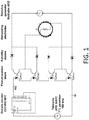
- the system uses four ground-independent switches in a "block" to preserve bidirectional conductance for bipolar stimulation.
- each electrode pole is connected to a collector-emitter connection of two serially connected phototransistors.
- the collector of the first phototransistor is connected to the cathode, and the emitter of the second phototransistor is connected to the anode of two diodes (e.g., Schottky diodes).
- the other pole of the diodes is connected together to one pole of the stimulus generator. This way the positive range of the stimulus waveform is conducted through the first diode-transistor pair while the second diode blocks the conduction toward the second transistor.
- the conduction happens oppositely: the second diode-transistor block is conducting, while the first diode-transistor block has high resistance.
- the other stimulus pole the same circuit is repeated.
- the LED parts of the four phototransistors belonging to one stimulating electrode pair are activated simultaneously by the output of a counter integrated circuit that is driven by any regular clock generators (e.g., any programmable microchip, 555 timer, etc.).
- Each output of the counter can drive one switching block of four transistors-two diodes, corresponding to one stimulating electrode pair.
- the concept can also be realized with any other bipolar ground-independent switches, and the locations of the electrodes on the head, the pattern of the electrode group assignments and their activation sequence being determined with respect to the individual variances of the subjects, and the location of the area to be targeted.
- the stimulus generator can be any ground-independent third party stimulus generator.
- the stimulator-side of the circuitry consists of completely passive, ground-independent components, which do not influence the floating character of the stimulus generator used.
- the counter side of the circuitry contains only low power components at low voltage level, and thus, can be operated by commercially available batteries (i.e., the counter side of the circuitry does not require a high-power power source).
- the phototransistors are in high-resistance state.
- the coupled stimulating electrodes can be considered electrically disconnected. Any arbitrary waveform having a predetermined frequency can be transmitted as the stimulus, which allows the system/method to be used in any type of electrical stimulation (e.g., direct current, alternating current, or random noise).
- small surface electrode refers to an electrode sized to allow placement of a desired number of electrodes, in particular, a minimum of three pairs, on the skull surface in an arrangement that leaves enough space between the pairs to avoid short circuiting. Preferably, a minimum of five to six pairs of electrodes are used. Small electrodes may include electrodes less than 5-by-5 cm, 5 cm diameter, or less than 20 cm 2 area. For example, five to six pairs of 2 cm by 2 cm small surface electrodes may be placed on one plane .
- large sponge electrode refers to an electrode configuration (one pair), or three electrode configurations having a size of 5-10cm by 5-10 cm, e.g., 5 cm by 5 cm or 10 cm by 10cm, or comparable sizes.
- Sponge electrodes are practical for transcutaneous use, as they easily pick up the shape of the head underneath.
- other electrode types are suitable (e.g. epidural plate electrodes, flexible electrocorticographic electrodes, metal surface electrodes deposited on flexible polymer substrates, metal screw electrodes penetrating the compact part of the skull, etc.).
- the electrodes are aligned such that the virtual axes determined by those electrode members of the groups which are set to different potential levels during stimulation cross each other at a predetermined focal point, either in one plane or in three dimensions (see FIG. 2B ).
- 6-8 electrode pairs are used. Using 6-8 electrode pairs causes a theoretical 6-8 fold drop in the apparent intensity at the skin immediately below each electrode if the electrode pairs are located far enough from each other (i.e., a distance that prevents the electrode pairs from touching each other and short-circuiting). However within the brain, at locations where the activity of all of the electrode pairs is present, the apparent current is higher, reaching the desired 1 mV/mm field strength.
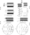
- FIG. 2A demonstrates the principle of spatio-temporally rotating intersectional short pulse (ISP) stimulation to spatially focus the effect of transcranial electrical stimulation (TES).
- Stimulus current is delivered sequentially through three independent electrode pairs generating a continuously changing intracerebral gradient pattern.
- Neuronal cell membranes can integrate these patterns due to their relatively slow membrane time-constant (approximately 10 ms). Consequently, neurons at the cross section of the current flow axes are cumulating the individual subthreshold effects of all stimuli, and become more strongly entrained than neurons located outside the focus.
- the method assumes a charge-integrating mechanism over time, exemplified here by a simplified leaky integrate-and-fire neuron model.
- An added advantage of fast pulses i.e., at least an order of magnitude shorter compared to the sampling interval of simultaneous neuronal recordings, e.g. 2.5 to10 ⁇ s duty cycle with 5 to 50 ⁇ s pause, depending on the number of electrode pairs
- fast pulses i.e., at least an order of magnitude shorter compared to the sampling interval of simultaneous neuronal recordings, e.g. 2.5 to10 ⁇ s duty cycle with 5 to 50 ⁇ s pause, depending on the number of electrode pairs
- LFP local field potentials
- neuronal spikes (1Hz - 5 kHz; 20 kHz sampling
- the ISP technique allows for generating apparently spatially concentrated electrical fields (from the neurons point of view, not physically) to selectively control activity also in subcortical structures and simultaneous recording of electrical activity.
- FIG. 1 Further experiments were performed on 19 healthy subjects using currents up to 7.5 mA of ISP stimulation ( FIG. 1 ).
- a circular array of 12 epicutaneous stimulation electrodes (six on each side) was placed around the head.
- Each stimulation site consisted of a 0.9% NaCl solution-soaked sponge square connected to 2 x 3 cm copper mesh.
- Scalp EEG was monitored by a 2-site montage (P3, P4).
- a one minute baseline recording was followed by a train of 1-Hz sinusoids with increasing and decreasing intensity (0, 1.5, 3, 4.5, 6, 7.5, 6, 4.5, 3, 1.5, 0 mA) for 12 seconds, repeated 60 times for each subject, and an additional one minute recovery session.
- Stimulation artifact generated by the 1 Hz modulator wave of the high frequency pulses was removed by an offline subtraction of a stimulus triggered moving average.
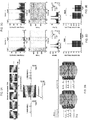
- the artifact-removed signal preserved the major features of the unstimulated control brain activity, as demonstrated by the non-zero peaked cross correlograms (i.e. phase-independent) and the weakly correlated instantaneous frequencies in the alpha band between the two EEG channels ( FIG. 6A ).
- a 4.5 mA stimulation or higher at 1 Hz induced various subjective effects, including a subjectively tolerable level of tingling and burning feeling of the skin. Onset and especially the offset of stimulation triggered phosphenes.
- Subjective feeling of head-movement and horizontally oscillating light in the visual field at the frequency of the stimulation was consistently reported even though the eyes were closed and testing was performed in semi-darkness.
- Feeling of a moving noise source in the horizontal plane at 1 Hz was present in some subjects at the highest intensities. At high intensities, each subject reported feeling of "metal taste" in the mouth. All subjective effects were stronger at the beginning of the stimulation and attenuated, but did not disappear, during the course of stimulation. No subjective or objective aftereffects were reported after the termination of the stimulation.
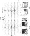
- FIG. 4A is showing five consecutive repetitions of the 12-second long stimulation in a subject. 12-16 Hz filtered (alpha rhythm, endogenous brain activity) EEG signals from the left and right hemisphere (colored traces) have a clear increase in amplitude only when the ISP stimulation is reaching high amplitudes (gray traces).
- TES phase modulation of the amplitude of alpha waves was visible on the filtered signal at high ISP intensities (6 and 7.5 mA; FIGS. 4a and 4b ).
- the LFP modulation was present in both hemispheres and alternated in phase, due to the shifting of the anodal-cathodal current direction (compare epochs in FIGS. 6a and 6b ).
- the mean alpha amplitudes around the stimulus peak (-135 to -45°) and around the stimulus trough (45 to 135°) were measured separately at P3 and P4 at each current intensity.
- Significant modulation of the LFP amplitude by the TES phase was observed at current intensities of 4.5, 6 and 7.5 mA at each hemisphere when the preferred current direction was applied ( FIG. 4C ).
- Neuronal excitability is largely determined by ionic conductances brought about by neurotransmitter-induced postsynaptic potentials. However, neurons can also sense electric fields. Because of the additive nature of the two polarizing mechanisms, theoretically no "minimum effective threshold" of the induced electric field exists. When a neuron is about to emit a spike, very small amounts of fields can bias spike threshold. Thus, when the V m of a neuron is known, very weak but perfectly-timed forced field can maximize the neuron's response. Endogenous brain rhythms are like a roller coaster, there are 'up' phases when the neurons are excitable, and 'down' phases of the rhythm when they are suppressed and it is the hardest to make them become active.
- the resistance of the skull attenuates the current flow further by another 20-30%, depending on the thickness of the skull. Given the importance of these attenuating factors, the amount of soft tissue, hair and skull thickness should be taken into account in estimating the effective current reaching the brain, and variation of these factors alone may explain the large individual variability of the effectiveness of transcutaneous electric stimulation.
- the concept of focusing intensity at circumscribed volumes of tissue is well established by radiological techniques such as cranial stereotactic radiosurgery.
- radiological techniques such as cranial stereotactic radiosurgery.
- simultaneously applied electric fields cannot be focused because of the common conductive media.
- the ISP exploits the time integrating property of the neuronal membrane (i.e., the membrane time constant of neurons at ⁇ 10 ms), by applying short and spatially rapidly changing sequential fields to establish spatial selectivity.
- the highest integral of transmembrane charge in neurons develop where successively induced electric fields multiple 'beams' intersect.
- the negligible artifacts produced by the ISP technique allowed for direct examination of the impact of scalp stimulation on brain waves in human volunteers.
- alpha power in the occipital areas was affected starting at 4.5 mA and consistent effects in each subjects were shown at > 7 mA currents, including amplitude modulation of alpha power as a function of phase of the 1 Hz cyclic field.
- Two custom designed stimulation strips were 3D printed and glued on the surfaces of the temporal bones bilaterally.
- Each of the two symmetric strips (width 13 mm, height 3.3 mm and wall thickness 0.7 mm) consisted of 5 individual pockets which were separated from each other by 3.7, 2.2, 2.2 and 3.7 mm ( FIG. 2B ), and their medial surfaces were resembling the temporal bone curvature of an MRI data based 3D model of a rat skull.
- the middle pockets were positioned at 5.16 mm posterior from Bregma.
- Two silicon probes were implanted at 5.16 mm posterior from Bregma and 4 mm lateral of the midline, in the CA1 regions of the hippocampi at both sides. ISP stimulation was performed in current controlled mode using the custom made electronics described below.
- Epicutaneous stimulating sponge electrodes for ISP were prepared from a 2 x 3 x 1.5 cm sponge glued to a 2 x 3 cm copper mesh, and glued to a rubber band with the sponges inside, keeping approximately 2.5 cm distances between sponges. The rubber band with the twelve electrodes were soaked in 0.9% saline solution and tightened gently around the head.
- flexible copper foils of the same size as above were glued on the 'skin' surface of the sponges, and the sponges were kept dry. Conductivity was further improved in both cases by putting electrode gel between the wet sponges or the copper foil and the skin.
- Sinusoid or DC stimulus waveforms were produced by an isolated stimulus generators, either in constant current mode or constant voltage mode.
- 10 cm-by-10 cm large sponge electrodes were used.
- VEP visually evoked potentials
- steady-state VEPs were played as a movie with 60 or 50 frame/s speed.
- the monitor refresh rate was adjusted to match the playback rates.
- Frame changes were monitored by a photodiode attached to the top-right edge of the monitor, where an alternating black-white square marked the consecutive frames.
- the photodiode signal was recorded in parallel with the EEG signals.
- the monitor was positioned approximately 15-20 cm in front of the subjects to observe the screen with both eyes.
- For VEP stimulation a full-screen, 10-by-10 flipping checkerboard pattern was presented 1200 times. Checkerboard flips took place every 500 ms.
- VEP stimulus was generated with 5 concentric - by - 12 circular sectors (60 sectors in total), maximum six segments visible simultaneously. Each stimulus was presented for 3 frames, resulting in a 20 or 16.6 Hz stimulation frequency (for 60 and 50 Hz refresh rate, respectively). 8000 stimuli were presented in each session.
- tcTES stimulation was alternatingly turned on and off every minute during VEP and ssVEP stimulation. To test whether the electromagnetic radiation of the monitor was picked up by the EEG wires and, therefore, produced VEP-like artefactual responses in the EEG signals, the eyes of the subject was covered by a card board, and the measurements were repeated.
- both positive and negative leads of the stimulus generators were connected to 12-12 'normally closed' type TLP52-4 phototransistors.
- Bidirectional, ground-independent conductivity was achieved the following way.
- Two phototransistors were serially coupled through their emitter and collector, and the input signal from the waveform generator was fed into both the emitter and the collector end of the transistor doublet, through two Schottky-diodes, which allowed current flow only to the appropriate member of the doublet, depending on the polarity of the signal.
- the common segment of transistor doublet was connected to a stimulation electrode on the head. The same circuit was constructed for the other pole of the signal as well.
- the next step in advancing the ISP technique is to increase the number of intersecting dipoles generated by pairs of stimulating electrodes and/or implanting them under the skin to eliminate skin shunting. For example, using a montage of 32 electrodes, a large number of dipoles can be formed to create a circumscribed 3-dimensional intersectional focus or target two or more brain structures while reducing the locally applied currents, potentially below skin sensation threshold.
- the matching of the electrodes to form an electrode group determines the focal point.
- the ISP method may be applied in many applications.
- the ISP method may be used for immediate intervention, e.g. in the supervision and termination of epileptic seizures.
- the ISP method may also be used as a possible treatment of other major neuropsychiatric disorders (e.g., depression or anxiety) by reaching a cumulative effect through repetitive interference with endogenous brain activity patterns ('treatment') across days.
- major neuropsychiatric disorders e.g., depression or anxiety
- ISP method examples include: post-stroke rehabilitation, enhancement of learning and memory recall, sleep quality enhancement, treatment of post-traumatic stress disorder, neuroscience research, transmission of general alerting signals to the brain in machine-brain interface applications, or any application which is currently targeted with transcranial direct current stimulation (tDCS), transcranial alternating current (tACS), other forms of transcranial electric stimulation methods using electrode pairs, transcranial magnetic stimulation, deep brain stimulation, or peripheral nerve stimulations.
- tDCS transcranial direct current stimulation
- tACS transcranial alternating current
- the ISP method may also be suitable for electrically stimulating other parts of the body, e.g. spinal cord, hearth, peripheral nerves, skeletal muscles. These lists are illustrative only, and the system and method described herein are not limited to these applications.
- the ISP method may also be applied using other electrode locations e.g.
- the concept of the ISP method i.e. the charge integration of multiple sequential electrical pulses by the neuronal (or glial) cell membranes does not depend on the electrode locations. Different electrode locations may imply the need of different current intensities to reach the desired effect.
- the ISP method recognizes that the simultaneous application of multiple electric fields through independent current generators cannot induce a spatially focused effect due to a spatially homogenous conductive medium. See FIG. 5 . Instead, the ISP method demonstrates the principle of spatio-temporally rotating intersectional short pulse (ISP) stimulation to spatially focus the effect of TES. The method assumes a charge-integrating mechanism over time.
- ISP intersectional short pulse
- An added advantage of fast pulses ( ⁇ 10 ⁇ s duty cycle with at least two times longer pause, depending on the number of electrode pairs) is that their high frequency only minimally affects simultaneous electric recording of local field potentials (LFP) or neuronal spikes (usually 1Hz - 5 kHz; 20 kHz sampling) and it does not saturate recording AC coupled amplifiers even at relatively high intensities.
- LFP local field potential
- neuronal spikes usually 1Hz - 5 kHz; 20 kHz sampling
- the system and method described above offers a better spatial focusing of the effect generated by non-invasive brain stimulation techniques that are currently available.
- the ISP system and method described above allow for the use of larger stimulus current intensities without intolerable effects experienced by the patient such as itching, skin-burning, etc.
- Differences between the system and method described in this application and the conventional electrical stimulation techniques include 1) the use of small surface electrodes rather than large sponge electrodes, 2) the use of multiple electrodes (e.g., electrode pairs or groups) aligned in a way that the axes of the concurrently active electrodes set to different potentials cross each other at a predetermined focal point, 3) delivering the stimulus waveform in a temporally segmented manner onto the electrodes, by activating two or more electrodes (e.g., a subset of the electrodes) at a time, 4) switching through all available electrodes within less than ten milliseconds, and 5) at any moment, the unused or deactivated electrodes are electrically decoupled from the stimulation circuit to avoid shunting.
- This list is illustrative only. One of ordinary skill in the art would have understood that other differences may exist between the system and method described in this application and the conventional electrical stimulation techniques.
- Embodiments of the subject matter and the operations described in this specification can be implemented in digital or analog electronic circuitry, with mechanic or optical switches, or in computer software embodied on a tangible medium, firmware, or hardware, including the structures disclosed in this specification and their structural equivalents, or in combinations of one or more of them.
- Embodiments of the subject matter described in this specification can be implemented as one or more computer programs, i.e., one or more modules of computer program instructions, encoded on one or more computer storage medium for execution by, or to control the operation of, data processing apparatus.
- the program instructions can be encoded on an artificially-generated propagated signal, e.g., a machine-generated electrical, optical, or electromagnetic signal that is generated to encode information for transmission to suitable receiver apparatus for execution by a data processing apparatus.
- a computer storage medium can be, or be included in, a computer-readable storage device, a computer-readable storage substrate, a random or serial access memory array or device, or a combination of one or more of them.
- a computer storage medium is not a propagated signal
- a computer storage medium can be a source or destination of computer program instructions encoded in an artificially-generated propagated signal.
- the computer storage medium can also be, or be included in, one or more separate components or media (e.g., multiple CDs, disks, or other storage devices). Accordingly, the computer storage medium may be tangible and non-transitory.
- the operations described in this specification can be implemented as operations performed by a data processing apparatus or processing circuit on data stored on one or more computer-readable storage devices or received from other sources.
- the apparatus can include special purpose logic circuitry, e.g., an FPGA (field programmable gate array) or an ASIC (application-specific integrated circuit).
- the apparatus can also include, in addition to hardware, code that creates an execution environment for the computer program in question, e.g., code that constitutes processor firmware, a protocol stack, a database management system, an operating system, a cross-platform runtime environment, a virtual machine, or a combination of one or more of them.
- the apparatus and execution environment can realize various different computing model infrastructures, such as web services, distributed computing and grid computing infrastructures.
- a computer program (also known as a program, software, software application, script, or code) can be written in any form of programming language, including compiled or interpreted languages, declarative or procedural languages, and it can be deployed in any form, including as a stand-alone program or as a module, component, subroutine, object, or other unit suitable for use in a computing environment.
- a computer program may, but need not, correspond to a file in a file system.
- a program can be stored in a portion of a file that holds other programs or data (e.g., one or more scripts stored in a markup language document), in a single file dedicated to the program in question, or in multiple coordinated files (e.g., files that store one or more modules, sub-programs, or portions of code).
- a computer program can be deployed to be executed on one computer or on multiple computers that are located at one site or distributed across multiple sites and interconnected by a communication network.
- the processes and logic flows described in this specification can be performed by one or more programmable processors or processing circuits executing one or more computer programs to perform actions by operating on input data and generating output.
- the processes and logic flows can also be performed by, and apparatus can also be implemented as, special purpose logic circuitry, e.g., an FPGA or an ASIC.
- processors or processing circuits suitable for the execution of a computer program include, by way of example, both general and special purpose microprocessors, and any one or more processors of any kind of digital computer.
- a processor will receive instructions and data from a read-only memory or a random access memory or both.
- the essential elements of a computer are a processor for performing actions in accordance with instructions and one or more memory devices for storing instructions and data.
- a computer will also include, or be operatively coupled to receive data from or transfer data to, or both, one or more mass storage devices for storing data, e.g., magnetic, magneto-optical disks, or optical disks.
- mass storage devices for storing data, e.g., magnetic, magneto-optical disks, or optical disks.
- a computer need not have such devices.
- a computer can be embedded in another device, e.g., a mobile telephone, a personal digital assistant (PDA), a mobile audio or video player, a game console, a Global Positioning System (GPS) receiver, or a portable storage device (e.g., a universal serial bus (USB) flash drive), to name just a few.
- Devices suitable for storing computer program instructions and data include all forms of non-volatile memory, media and memory devices, including by way of example semiconductor memory devices, e.g., EPROM, EEPROM, and flash memory devices; magnetic disks, e.g., internal hard disks or removable disks; magneto-optical disks; and CD-ROM and DVD-ROM disks.
- the processor and the memory can be supplemented by, or incorporated in, special purpose logic circuitry.
- embodiments of the subject matter described in this specification can be implemented on a computer having a display device, e.g., a CRT (cathode ray tube) or LCD (liquid crystal display), OLED (organic light emitting diode), TFT (thin-film transistor), plasma, other flexible configuration, or any other monitor for displaying information to the user and a keyboard, a pointing device, e.g., a mouse trackball, etc., or a touch screen, touch pad, etc., by which the user can provide input to the computer.
- a display device e.g., a CRT (cathode ray tube) or LCD (liquid crystal display), OLED (organic light emitting diode), TFT (thin-film transistor), plasma, other flexible configuration, or any other monitor for displaying information to the user and a keyboard, a pointing device, e.g., a mouse trackball, etc., or a touch screen, touch pad, etc., by which the user can provide input to the computer
- a computer can interact with a user by sending documents to and receiving documents from a device that is used by the user; for example, by sending web pages to a web browser on a user's client device in response to requests received from the web browser.
Landscapes
- Health & Medical Sciences (AREA)
- Life Sciences & Earth Sciences (AREA)
- Veterinary Medicine (AREA)
- Public Health (AREA)
- General Health & Medical Sciences (AREA)
- Biomedical Technology (AREA)
- Engineering & Computer Science (AREA)
- Animal Behavior & Ethology (AREA)
- Biophysics (AREA)
- Heart & Thoracic Surgery (AREA)
- Radiology & Medical Imaging (AREA)
- Nuclear Medicine, Radiotherapy & Molecular Imaging (AREA)
- Psychology (AREA)
- Psychiatry (AREA)
- Pathology (AREA)
- Physics & Mathematics (AREA)
- Surgery (AREA)
- Molecular Biology (AREA)
- Medical Informatics (AREA)
- Developmental Disabilities (AREA)
- Child & Adolescent Psychology (AREA)
- Social Psychology (AREA)
- Hospice & Palliative Care (AREA)
- Neurology (AREA)
- Physiology (AREA)
- Electrotherapy Devices (AREA)
- Magnetic Treatment Devices (AREA)
- Measurement And Recording Of Electrical Phenomena And Electrical Characteristics Of The Living Body (AREA)
Claims (12)
- Système de stimulation électrique du cerveau comprenant :une pluralité d'électrodes agencées en une pluralité de groupes d'électrodes, chaque groupe d'électrodes comprenant au moins deux électrodes où au moins une électrode est réglée à un niveau de potentiel différent de telle sorte qu'une différence de tension est générée entre les membres d'un groupe d'électrodes, la pluralité d'électrodes étant agencée sur l'un parmiune surface extérieure du cuir chevelu d'un patient,une surface extérieure du crâne du patient,dans le crâne du patient, sur la surface du cerveau ou de la dure-mère du patient, oudans le cerveau du patient ;un circuit de commutation indépendant de la masse configuré pour activer et désactiver sélectivement des groupes d'électrodes par l'intermédiaire d'au moins un commutateur indépendant de la masse ; etdans lequel des axes reliant des électrodes réglées à différents niveaux de potentiel dans chaque groupe d'électrodes ou des axes de champs électriques générés se croisent en un ou plusieurs points focaux prédéterminés,dans lequel le circuit de commutation indépendant de la masse est programmé pour activer et désactiver séquentiellement des groupes d'électrodes, etdans lequel le système utilise les propriétés capacitives d'une membrane de cellule neuronale et/ou gliale pour mettre en œuvre un mécanisme d'intégration de charge, qui intègre temporellement un effet de multiples impulsions électriques indépendantes et séquentielles délivrées à travers les au moins deux électrodes activées.
- Système selon la revendication 1, dans lequel chaque électrode de la pluralité d'électrodes est un membre de plus d'un groupe d'électrodes.
- Système selon la revendication 1, dans lequel chaque électrode de la pluralité d'électrodes est un membre d'un seul groupe d'électrodes.
- Système selon la revendication 1, dans lequel un cycle comprend une activation et une désactivation de chaque électrode dans un groupe d'électrodes, et une durée du cycle est de 1 à 100 millisecondes.
- Système selon la revendication 4, dans lequel chaque groupe d'électrodes est activé pendant moins de 3,5 ms.
- Système selon la revendication 4, dans lequel un temps de pause entre des réactivations consécutives de quelconques groupes d'électrodes est au moins deux fois plus long que la durée de son activation précédente.
- Système selon la revendication 1, dans lequel un cycle comprend une activation et une désactivation de chaque électrode dans un groupe d'électrodes, et une durée du cycle est inférieure à une constante de temps de la membrane de cellule neuronale et/ou gliale.
- Système selon la revendication 1, dans lequel le circuit de commutation indépendant de la masse comprendl'au moins un commutateur indépendant de la masse, qui est configuré pour connecter ou déconnecter au moins deux lignes de signaux ;au moins une diode ; etun circuit de commande configuré pour piloter l'au moins un commutateur indépendant de la masse.
- Système selon la revendication 8, dans lequel :(i) l'au moins un commutateur indépendant de la masse comprend un phototransistor ; ou (ii) le circuit de commutation indépendant de la masse comprend une pluralité de commutateurs indépendants de la masse configurés pour connecter ou déconnecter au moins deux lignes de signaux, une pluralité de diodes et un circuit de commande configuré pour piloter la pluralité de commutateurs indépendants de la masse,la pluralité de commutateurs indépendants de la masse comprend une pluralité de phototransistors, etchaque pôle d'électrode est connecté à une liaison collecteur-émetteur de deux phototransistors connectés en série.
- Système selon la revendication 1, dans lequel la pluralité d'électrodes comprend :(i) une pluralité de petites électrodes de surface ; ou(ii) une pluralité de grandes électrodes en éponge.
- Système selon la revendication 1, comprenant en outre une source de courant ou de tension.
- Système selon la revendication 10, partie (ii) dans lequel un groupe d'électrodes comprend une paire d'électrodes dans laquelle deux électrodes sont configurées de telle sorte qu'une première électrode est physiquement connectée soit temporairement, soit constamment à un pôle de la source de courant ou de tension, et un second pôle est connecté à un second pôle de la source de courant ou de tension.
Applications Claiming Priority (2)
| Application Number | Priority Date | Filing Date | Title |
|---|---|---|---|
| US201762508251P | 2017-05-18 | 2017-05-18 | |
| PCT/US2018/033253 WO2018213622A1 (fr) | 2017-05-18 | 2018-05-17 | Stimulation électrique à impulsions courtes croisée du cerveau |
Publications (3)
| Publication Number | Publication Date |
|---|---|
| EP3624891A1 EP3624891A1 (fr) | 2020-03-25 |
| EP3624891A4 EP3624891A4 (fr) | 2020-12-16 |
| EP3624891B1 true EP3624891B1 (fr) | 2021-12-08 |
Family
ID=64274687
Family Applications (1)
| Application Number | Title | Priority Date | Filing Date |
|---|---|---|---|
| EP18803289.0A Active EP3624891B1 (fr) | 2017-05-18 | 2018-05-17 | Stimulation électrique à impulsions courtes croisée du cerveau |
Country Status (10)
| Country | Link |
|---|---|
| US (1) | US11452862B2 (fr) |
| EP (1) | EP3624891B1 (fr) |
| JP (1) | JP7162225B2 (fr) |
| KR (1) | KR102633307B1 (fr) |
| CN (1) | CN110913946B (fr) |
| CA (1) | CA3063716A1 (fr) |
| DK (1) | DK3624891T3 (fr) |
| HU (1) | HUE058278T2 (fr) |
| IL (1) | IL270667B2 (fr) |
| WO (1) | WO2018213622A1 (fr) |
Families Citing this family (9)
| Publication number | Priority date | Publication date | Assignee | Title |
|---|---|---|---|---|
| US10736557B2 (en) | 2016-03-30 | 2020-08-11 | Brain F.I.T. Imaging, LLC | Methods and magnetic imaging devices to inventory human brain cortical function |
| US11337631B2 (en) | 2017-10-03 | 2022-05-24 | Brainn F.I.T. Imaging, LLC | Methods and magnetic imaging devices to inventory human brain cortical function |
| US12274560B2 (en) | 2018-12-14 | 2025-04-15 | Brainpatch Limited | System and method for implementing a stimulation protocol |
| GB2579827A (en) * | 2018-12-14 | 2020-07-08 | Brainpatch Ltd | Brain interfacing apparatus and method |
| US11832966B2 (en) * | 2019-04-03 | 2023-12-05 | Brain F.I.T. Imaging, LLC | Methods and magnetic imaging devices to inventory human brain cortical function |
| US11445960B2 (en) * | 2019-10-09 | 2022-09-20 | Trustees Of Boston University | Electrography system employing layered electrodes for improved spatial resolution |
| AU2021338673A1 (en) * | 2020-09-08 | 2023-05-25 | Oscilloscape, LLC | Methods and systems for neural stimulation via music and synchronized rhythmic stimulation |
| CN114587386B (zh) * | 2020-12-07 | 2025-07-29 | 中国科学院深圳先进技术研究院 | 处理皮层-皮质间诱发电位的病理网络连接方法 |
| DE102021106334A1 (de) | 2021-03-16 | 2022-09-22 | Technische Universität Ilmenau, Körperschaft des öffentlichen Rechts, vertreten durch den Rektor | Verfahren und System zur Erzeugung und Applikation von Stimulationskonfigurationen am Menschen sowie dazugehöriges Computerprogramm |
Family Cites Families (20)
| Publication number | Priority date | Publication date | Assignee | Title |
|---|---|---|---|---|
| US5782874A (en) * | 1993-05-28 | 1998-07-21 | Loos; Hendricus G. | Method and apparatus for manipulating nervous systems |
| US20040167586A1 (en) * | 2003-02-21 | 2004-08-26 | Overstreet Edward H. | Charge normalization for electrical stimulation of excitable tissue to facilitate the comparison of neural responses to behavioral measurements having different parameters |
| AU2004226596C1 (en) * | 2003-04-02 | 2010-09-16 | Neurostream Technologies General Partnership | Implantable nerve signal sensing and stimulation device for treating foot drop and other neurological disorders |
| DE10318071A1 (de) | 2003-04-17 | 2004-11-25 | Forschungszentrum Jülich GmbH | Vorrichtung zur Desynchronisation von neuronaler Hirnaktivität |
| US20060106430A1 (en) * | 2004-11-12 | 2006-05-18 | Brad Fowler | Electrode configurations for reducing invasiveness and/or enhancing neural stimulation efficacy, and associated methods |
| US9913985B2 (en) * | 2006-04-28 | 2018-03-13 | Second Sight Medical Products, Inc. | Method and apparatus to provide safety checks for neural stimulation |
| US8606360B2 (en) * | 2006-03-09 | 2013-12-10 | The Cleveland Clinic Foundation | Systems and methods for determining volume of activation for spinal cord and peripheral nerve stimulation |
| ES2664415T3 (es) * | 2006-07-05 | 2018-04-19 | Precisis Ag | Sistema para el tratamiento de trastornos neurológicos mediante estimulación eléctrica |
| GB0709834D0 (en) | 2007-05-22 | 2007-07-04 | Gillbe Ivor S | Array stimulator |
| EP2405970B1 (fr) | 2009-03-02 | 2018-04-25 | Yeda Research and Development Co., Ltd. | Configuration magnétique et schéma de temporisation pour stimulation magnétique transcrânienne |
| US20110000777A1 (en) * | 2009-07-03 | 2011-01-06 | Zhou yun yan | Vapor compression distillation system |
| US8452414B2 (en) * | 2009-09-29 | 2013-05-28 | Medtronic, Inc. | Steering stimulation current by employing steering current |
| DE102011120213A1 (de) * | 2010-12-28 | 2012-06-28 | Ebs Technologies Gmbh | Vorrichtung zur nicht-invasiven, elektrischen Tiefenhirnstimulation |
| WO2013192582A1 (fr) | 2012-06-22 | 2013-12-27 | Neurotrek , Inc. | Dispositif et procédés pour une neuromodulation non effractive à l'aide d'une stimulation électrique crânienne ciblée |
| KR20150135618A (ko) * | 2014-05-22 | 2015-12-03 | 주식회사 유진엘이디 | 치료 또는 미용용 발광모듈 |
| CN106687174B (zh) * | 2014-09-23 | 2019-12-03 | 波士顿科学神经调制公司 | 专用于针对目标组织的调制场的目标函数的神经调制 |
| WO2016057855A1 (fr) | 2014-10-08 | 2016-04-14 | Massachusetts Institute Of Technology | Procédés et appareil de stimulation de tissu biologique |
| US10201708B2 (en) * | 2014-10-29 | 2019-02-12 | Dirk De Ridder | Method of treating a neurological disorder using network stimulation |
| WO2016095810A1 (fr) * | 2014-12-19 | 2016-06-23 | Chongqing Derma Optic&Electronic Technique Co., Ltd. | Appareil de traitement par radiofréquence |
| DE102015109988B4 (de) * | 2015-06-22 | 2017-04-27 | Forschungszentrum Jülich GmbH | Vorrichtung zur effektiven invasiven Zwei-Stufen-Neurostimulation |
-
2018
- 2018-05-17 US US16/613,400 patent/US11452862B2/en active Active
- 2018-05-17 CN CN201880045867.5A patent/CN110913946B/zh active Active
- 2018-05-17 DK DK18803289.0T patent/DK3624891T3/da active
- 2018-05-17 WO PCT/US2018/033253 patent/WO2018213622A1/fr not_active Ceased
- 2018-05-17 CA CA3063716A patent/CA3063716A1/fr active Pending
- 2018-05-17 EP EP18803289.0A patent/EP3624891B1/fr active Active
- 2018-05-17 IL IL270667A patent/IL270667B2/en unknown
- 2018-05-17 HU HUE18803289A patent/HUE058278T2/hu unknown
- 2018-05-17 JP JP2020514143A patent/JP7162225B2/ja active Active
- 2018-05-17 KR KR1020197037093A patent/KR102633307B1/ko active Active
Also Published As
| Publication number | Publication date |
|---|---|
| KR20200023289A (ko) | 2020-03-04 |
| CN110913946A (zh) | 2020-03-24 |
| CA3063716A1 (fr) | 2018-11-22 |
| HUE058278T2 (hu) | 2022-07-28 |
| US11452862B2 (en) | 2022-09-27 |
| IL270667B1 (en) | 2023-05-01 |
| BR112019024086A2 (pt) | 2020-06-02 |
| IL270667B2 (en) | 2023-09-01 |
| CN110913946B (zh) | 2023-08-01 |
| JP7162225B2 (ja) | 2022-10-28 |
| WO2018213622A1 (fr) | 2018-11-22 |
| US20200164201A1 (en) | 2020-05-28 |
| EP3624891A4 (fr) | 2020-12-16 |
| EP3624891A1 (fr) | 2020-03-25 |
| DK3624891T3 (da) | 2022-01-03 |
| IL270667A (fr) | 2019-12-31 |
| KR102633307B1 (ko) | 2024-02-05 |
| JP2020520778A (ja) | 2020-07-16 |
Similar Documents
| Publication | Publication Date | Title |
|---|---|---|
| EP3624891B1 (fr) | Stimulation électrique à impulsions courtes croisée du cerveau | |
| Vöröslakos et al. | Direct effects of transcranial electric stimulation on brain circuits in rats and humans | |
| Reinhart et al. | Using transcranial direct-current stimulation (tDCS) to understand cognitive processing | |
| Di Lazzaro et al. | Transcranial direct current stimulation effects on the excitability of corticospinal axons of the human cerebral cortex | |
| EP3171928B1 (fr) | Stimulation pulsée pour traiter l'oeil sec | |
| Moreno-Duarte et al. | Transcranial electrical stimulation: Transcranial direct current stimulation (tDCS), transcranial alternating current stimulation (tACS), transcranial pulsed current stimulation (tPCS), and transcranial random noise stimulation (tRNS) | |
| US10537729B2 (en) | Trigeminal neurostimulation based upon pulse counting and chronobiology | |
| Groppa et al. | Slow-oscillatory transcranial direct current stimulation can induce bidirectional shifts in motor cortical excitability in awake humans | |
| US20140303425A1 (en) | Method and apparatus for electromagnetic treatment of cognition and neurological injury | |
| US10543367B2 (en) | Transcranial burst electrostimulation apparatus and its applications | |
| Zaaimi et al. | Multi-electrode stimulation in somatosensory cortex increases probability of detection | |
| MX2012004050A (es) | Dispositivos, sistemas y metodos para el tratamiento de alteraciones neurosiquiatricas. | |
| TWI573606B (zh) | 經顱陣發型電刺激裝置及其應用 | |
| Alberts | A simple view of parkinsonian tremor. Electrical stimulation of cortex adjacent to the rolandic fissure in awake man | |
| Boutabla et al. | Simultaneous activation of multiple vestibular pathways upon electrical stimulation of semicircular canal afferents | |
| Efthimiou et al. | Application of facial neuromuscular electrical stimulation (fNMES) in psychophysiological research: Practical recommendations based on a systematic review of the literature | |
| McDonnall et al. | Restoration of blink in facial paralysis patients using FES | |
| WO2022146294A1 (fr) | Système et méthode dans lesquels le nerf vague auriculaire est stimulé par courant continu intermittent pour le traitement de maladies et de troubles | |
| US11571541B2 (en) | Apparatus and methods of transcranial stimulation to adjust sensory cortical dendritic spine neck membrane potentials for altering consciousness | |
| Richardson et al. | Somatosensory encoding with cuneate nucleus microstimulation: effects on downstream cortical activity | |
| BR112019024086B1 (pt) | Sistema para estimulação elétrica cerebral, e, método de estimulação elétrica cerebral | |
| Thompson et al. | A tutorial for transcranial magnetic and electrical stimulations in cognitive psychology | |
| Najib et al. | Paradoxical functional facilitation with noninvasive brain stimulation | |
| Vöröslakos | Spatially and temporally targeted neuromodulation by transcranial electrical stimulation | |
| JP4545721B2 (ja) | 連続パルス式非変調非バーストモード神経刺激装置を用いて有効性及び感覚許容度を向上させる方法 |
Legal Events
| Date | Code | Title | Description |
|---|---|---|---|
| STAA | Information on the status of an ep patent application or granted ep patent |
Free format text: STATUS: THE INTERNATIONAL PUBLICATION HAS BEEN MADE |
|
| PUAI | Public reference made under article 153(3) epc to a published international application that has entered the european phase |
Free format text: ORIGINAL CODE: 0009012 |
|
| STAA | Information on the status of an ep patent application or granted ep patent |
Free format text: STATUS: REQUEST FOR EXAMINATION WAS MADE |
|
| 17P | Request for examination filed |
Effective date: 20191126 |
|
| AK | Designated contracting states |
Kind code of ref document: A1 Designated state(s): AL AT BE BG CH CY CZ DE DK EE ES FI FR GB GR HR HU IE IS IT LI LT LU LV MC MK MT NL NO PL PT RO RS SE SI SK SM TR |
|
| AX | Request for extension of the european patent |
Extension state: BA ME |
|
| DAV | Request for validation of the european patent (deleted) | ||
| DAX | Request for extension of the european patent (deleted) | ||
| A4 | Supplementary search report drawn up and despatched |
Effective date: 20201113 |
|
| RIC1 | Information provided on ipc code assigned before grant |
Ipc: A61N 1/36 20060101AFI20201109BHEP Ipc: A61N 1/04 20060101ALI20201109BHEP Ipc: A61B 5/0484 20060101ALI20201109BHEP |
|
| GRAP | Despatch of communication of intention to grant a patent |
Free format text: ORIGINAL CODE: EPIDOSNIGR1 |
|
| STAA | Information on the status of an ep patent application or granted ep patent |
Free format text: STATUS: GRANT OF PATENT IS INTENDED |
|
| RIC1 | Information provided on ipc code assigned before grant |
Ipc: A61N 1/36 20060101AFI20210705BHEP Ipc: A61N 1/04 20060101ALI20210705BHEP Ipc: A61B 5/377 20210101ALI20210705BHEP |
|
| INTG | Intention to grant announced |
Effective date: 20210721 |
|
| GRAS | Grant fee paid |
Free format text: ORIGINAL CODE: EPIDOSNIGR3 |
|
| GRAA | (expected) grant |
Free format text: ORIGINAL CODE: 0009210 |
|
| STAA | Information on the status of an ep patent application or granted ep patent |
Free format text: STATUS: THE PATENT HAS BEEN GRANTED |
|
| AK | Designated contracting states |
Kind code of ref document: B1 Designated state(s): AL AT BE BG CH CY CZ DE DK EE ES FI FR GB GR HR HU IE IS IT LI LT LU LV MC MK MT NL NO PL PT RO RS SE SI SK SM TR |
|
| REG | Reference to a national code |
Ref country code: GB Ref legal event code: FG4D |
|
| REG | Reference to a national code |
Ref country code: AT Ref legal event code: REF Ref document number: 1453302 Country of ref document: AT Kind code of ref document: T Effective date: 20211215 Ref country code: CH Ref legal event code: EP |
|
| REG | Reference to a national code |
Ref country code: DE Ref legal event code: R096 Ref document number: 602018027967 Country of ref document: DE |
|
| REG | Reference to a national code |
Ref country code: SE Ref legal event code: TRGR |
|
| REG | Reference to a national code |
Ref country code: DK Ref legal event code: T3 Effective date: 20211220 |
|
| REG | Reference to a national code |
Ref country code: IE Ref legal event code: FG4D |
|
| REG | Reference to a national code |
Ref country code: NL Ref legal event code: FP |
|
| REG | Reference to a national code |
Ref country code: LT Ref legal event code: MG9D |
|
| PG25 | Lapsed in a contracting state [announced via postgrant information from national office to epo] |
Ref country code: RS Free format text: LAPSE BECAUSE OF FAILURE TO SUBMIT A TRANSLATION OF THE DESCRIPTION OR TO PAY THE FEE WITHIN THE PRESCRIBED TIME-LIMIT Effective date: 20211208 Ref country code: LT Free format text: LAPSE BECAUSE OF FAILURE TO SUBMIT A TRANSLATION OF THE DESCRIPTION OR TO PAY THE FEE WITHIN THE PRESCRIBED TIME-LIMIT Effective date: 20211208 Ref country code: FI Free format text: LAPSE BECAUSE OF FAILURE TO SUBMIT A TRANSLATION OF THE DESCRIPTION OR TO PAY THE FEE WITHIN THE PRESCRIBED TIME-LIMIT Effective date: 20211208 Ref country code: BG Free format text: LAPSE BECAUSE OF FAILURE TO SUBMIT A TRANSLATION OF THE DESCRIPTION OR TO PAY THE FEE WITHIN THE PRESCRIBED TIME-LIMIT Effective date: 20220308 |
|
| REG | Reference to a national code |
Ref country code: NO Ref legal event code: T2 Effective date: 20211208 |
|
| PG25 | Lapsed in a contracting state [announced via postgrant information from national office to epo] |
Ref country code: LV Free format text: LAPSE BECAUSE OF FAILURE TO SUBMIT A TRANSLATION OF THE DESCRIPTION OR TO PAY THE FEE WITHIN THE PRESCRIBED TIME-LIMIT Effective date: 20211208 Ref country code: HR Free format text: LAPSE BECAUSE OF FAILURE TO SUBMIT A TRANSLATION OF THE DESCRIPTION OR TO PAY THE FEE WITHIN THE PRESCRIBED TIME-LIMIT Effective date: 20211208 Ref country code: GR Free format text: LAPSE BECAUSE OF FAILURE TO SUBMIT A TRANSLATION OF THE DESCRIPTION OR TO PAY THE FEE WITHIN THE PRESCRIBED TIME-LIMIT Effective date: 20220309 Ref country code: ES Free format text: LAPSE BECAUSE OF FAILURE TO SUBMIT A TRANSLATION OF THE DESCRIPTION OR TO PAY THE FEE WITHIN THE PRESCRIBED TIME-LIMIT Effective date: 20211208 |
|
| REG | Reference to a national code |
Ref country code: HU Ref legal event code: AG4A Ref document number: E058278 Country of ref document: HU |
|
| PG25 | Lapsed in a contracting state [announced via postgrant information from national office to epo] |
Ref country code: SM Free format text: LAPSE BECAUSE OF FAILURE TO SUBMIT A TRANSLATION OF THE DESCRIPTION OR TO PAY THE FEE WITHIN THE PRESCRIBED TIME-LIMIT Effective date: 20211208 Ref country code: SK Free format text: LAPSE BECAUSE OF FAILURE TO SUBMIT A TRANSLATION OF THE DESCRIPTION OR TO PAY THE FEE WITHIN THE PRESCRIBED TIME-LIMIT Effective date: 20211208 Ref country code: RO Free format text: LAPSE BECAUSE OF FAILURE TO SUBMIT A TRANSLATION OF THE DESCRIPTION OR TO PAY THE FEE WITHIN THE PRESCRIBED TIME-LIMIT Effective date: 20211208 Ref country code: PT Free format text: LAPSE BECAUSE OF FAILURE TO SUBMIT A TRANSLATION OF THE DESCRIPTION OR TO PAY THE FEE WITHIN THE PRESCRIBED TIME-LIMIT Effective date: 20220408 Ref country code: EE Free format text: LAPSE BECAUSE OF FAILURE TO SUBMIT A TRANSLATION OF THE DESCRIPTION OR TO PAY THE FEE WITHIN THE PRESCRIBED TIME-LIMIT Effective date: 20211208 Ref country code: CZ Free format text: LAPSE BECAUSE OF FAILURE TO SUBMIT A TRANSLATION OF THE DESCRIPTION OR TO PAY THE FEE WITHIN THE PRESCRIBED TIME-LIMIT Effective date: 20211208 |
|
| PG25 | Lapsed in a contracting state [announced via postgrant information from national office to epo] |
Ref country code: PL Free format text: LAPSE BECAUSE OF FAILURE TO SUBMIT A TRANSLATION OF THE DESCRIPTION OR TO PAY THE FEE WITHIN THE PRESCRIBED TIME-LIMIT Effective date: 20211208 |
|
| REG | Reference to a national code |
Ref country code: DE Ref legal event code: R097 Ref document number: 602018027967 Country of ref document: DE |
|
| PG25 | Lapsed in a contracting state [announced via postgrant information from national office to epo] |
Ref country code: IS Free format text: LAPSE BECAUSE OF FAILURE TO SUBMIT A TRANSLATION OF THE DESCRIPTION OR TO PAY THE FEE WITHIN THE PRESCRIBED TIME-LIMIT Effective date: 20220408 |
|
| PLBE | No opposition filed within time limit |
Free format text: ORIGINAL CODE: 0009261 |
|
| STAA | Information on the status of an ep patent application or granted ep patent |
Free format text: STATUS: NO OPPOSITION FILED WITHIN TIME LIMIT |
|
| PG25 | Lapsed in a contracting state [announced via postgrant information from national office to epo] |
Ref country code: AL Free format text: LAPSE BECAUSE OF FAILURE TO SUBMIT A TRANSLATION OF THE DESCRIPTION OR TO PAY THE FEE WITHIN THE PRESCRIBED TIME-LIMIT Effective date: 20211208 |
|
| 26N | No opposition filed |
Effective date: 20220909 |
|
| PG25 | Lapsed in a contracting state [announced via postgrant information from national office to epo] |
Ref country code: SI Free format text: LAPSE BECAUSE OF FAILURE TO SUBMIT A TRANSLATION OF THE DESCRIPTION OR TO PAY THE FEE WITHIN THE PRESCRIBED TIME-LIMIT Effective date: 20211208 |
|
| PG25 | Lapsed in a contracting state [announced via postgrant information from national office to epo] |
Ref country code: MC Free format text: LAPSE BECAUSE OF FAILURE TO SUBMIT A TRANSLATION OF THE DESCRIPTION OR TO PAY THE FEE WITHIN THE PRESCRIBED TIME-LIMIT Effective date: 20211208 Ref country code: LU Free format text: LAPSE BECAUSE OF NON-PAYMENT OF DUE FEES Effective date: 20220517 |
|
| PG25 | Lapsed in a contracting state [announced via postgrant information from national office to epo] |
Ref country code: IE Free format text: LAPSE BECAUSE OF NON-PAYMENT OF DUE FEES Effective date: 20220517 |
|
| REG | Reference to a national code |
Ref country code: AT Ref legal event code: UEP Ref document number: 1453302 Country of ref document: AT Kind code of ref document: T Effective date: 20211208 |
|
| P01 | Opt-out of the competence of the unified patent court (upc) registered |
Effective date: 20230719 |
|
| PG25 | Lapsed in a contracting state [announced via postgrant information from national office to epo] |
Ref country code: MK Free format text: LAPSE BECAUSE OF FAILURE TO SUBMIT A TRANSLATION OF THE DESCRIPTION OR TO PAY THE FEE WITHIN THE PRESCRIBED TIME-LIMIT Effective date: 20211208 Ref country code: CY Free format text: LAPSE BECAUSE OF FAILURE TO SUBMIT A TRANSLATION OF THE DESCRIPTION OR TO PAY THE FEE WITHIN THE PRESCRIBED TIME-LIMIT Effective date: 20211208 |
|
| PG25 | Lapsed in a contracting state [announced via postgrant information from national office to epo] |
Ref country code: MT Free format text: LAPSE BECAUSE OF FAILURE TO SUBMIT A TRANSLATION OF THE DESCRIPTION OR TO PAY THE FEE WITHIN THE PRESCRIBED TIME-LIMIT Effective date: 20211208 |
|
| PGFP | Annual fee paid to national office [announced via postgrant information from national office to epo] |
Ref country code: DE Payment date: 20250325 Year of fee payment: 8 |
|
| PGFP | Annual fee paid to national office [announced via postgrant information from national office to epo] |
Ref country code: DK Payment date: 20250516 Year of fee payment: 8 |
|
| PGFP | Annual fee paid to national office [announced via postgrant information from national office to epo] |
Ref country code: HU Payment date: 20250415 Year of fee payment: 8 Ref country code: NO Payment date: 20250509 Year of fee payment: 8 |
|
| PGFP | Annual fee paid to national office [announced via postgrant information from national office to epo] |
Ref country code: BE Payment date: 20250410 Year of fee payment: 8 Ref country code: IT Payment date: 20250422 Year of fee payment: 8 |
|
| PGFP | Annual fee paid to national office [announced via postgrant information from national office to epo] |
Ref country code: CH Payment date: 20250601 Year of fee payment: 8 |
|
| PGFP | Annual fee paid to national office [announced via postgrant information from national office to epo] |
Ref country code: AT Payment date: 20250425 Year of fee payment: 8 |
|
| PG25 | Lapsed in a contracting state [announced via postgrant information from national office to epo] |
Ref country code: TR Free format text: LAPSE BECAUSE OF FAILURE TO SUBMIT A TRANSLATION OF THE DESCRIPTION OR TO PAY THE FEE WITHIN THE PRESCRIBED TIME-LIMIT Effective date: 20211208 |
|
| PGFP | Annual fee paid to national office [announced via postgrant information from national office to epo] |
Ref country code: SE Payment date: 20260312 Year of fee payment: 9 |
|
| PGFP | Annual fee paid to national office [announced via postgrant information from national office to epo] |
Ref country code: GB Payment date: 20260312 Year of fee payment: 9 |
|
| PGFP | Annual fee paid to national office [announced via postgrant information from national office to epo] |
Ref country code: NL Payment date: 20260317 Year of fee payment: 9 |
|
| PGFP | Annual fee paid to national office [announced via postgrant information from national office to epo] |
Ref country code: FR Payment date: 20260309 Year of fee payment: 9 |