EP3625110B1 - Direction électromécanique assistée de véhicule - Google Patents
Direction électromécanique assistée de véhicule Download PDFInfo
- Publication number
- EP3625110B1 EP3625110B1 EP18717886.8A EP18717886A EP3625110B1 EP 3625110 B1 EP3625110 B1 EP 3625110B1 EP 18717886 A EP18717886 A EP 18717886A EP 3625110 B1 EP3625110 B1 EP 3625110B1
- Authority
- EP
- European Patent Office
- Prior art keywords
- steering
- worm wheel
- pinion
- rotation
- axis
- Prior art date
- Legal status (The legal status is an assumption and is not a legal conclusion. Google has not performed a legal analysis and makes no representation as to the accuracy of the status listed.)
- Active
Links
Images
Classifications
-
- B—PERFORMING OPERATIONS; TRANSPORTING
- B62—LAND VEHICLES FOR TRAVELLING OTHERWISE THAN ON RAILS
- B62D—MOTOR VEHICLES; TRAILERS
- B62D5/00—Power-assisted or power-driven steering
- B62D5/04—Power-assisted or power-driven steering electrical, e.g. using an electric servo-motor connected to, or forming part of, the steering gear
- B62D5/0421—Electric motor acting on or near steering gear
- B62D5/0424—Electric motor acting on or near steering gear the axes of motor and final driven element of steering gear, e.g. rack, being parallel
- B62D5/0427—Electric motor acting on or near steering gear the axes of motor and final driven element of steering gear, e.g. rack, being parallel the axes being coaxial
-
- B—PERFORMING OPERATIONS; TRANSPORTING
- B62—LAND VEHICLES FOR TRAVELLING OTHERWISE THAN ON RAILS
- B62D—MOTOR VEHICLES; TRAILERS
- B62D5/00—Power-assisted or power-driven steering
- B62D5/04—Power-assisted or power-driven steering electrical, e.g. using an electric servo-motor connected to, or forming part of, the steering gear
- B62D5/0421—Electric motor acting on or near steering gear
-
- B—PERFORMING OPERATIONS; TRANSPORTING
- B62—LAND VEHICLES FOR TRAVELLING OTHERWISE THAN ON RAILS
- B62D—MOTOR VEHICLES; TRAILERS
- B62D3/00—Steering gears
- B62D3/02—Steering gears mechanical
- B62D3/04—Steering gears mechanical of worm type
-
- B—PERFORMING OPERATIONS; TRANSPORTING
- B62—LAND VEHICLES FOR TRAVELLING OTHERWISE THAN ON RAILS
- B62D—MOTOR VEHICLES; TRAILERS
- B62D7/00—Steering linkage; Stub axles or their mountings
- B62D7/16—Arrangement of linkage connections
Definitions
- the invention relates to an electromechanical motor vehicle steering system, comprising a steering column, a rack, a steering pinion which couples the steering column to the rack, and an electric drive device with an electric motor and a worm wheel, which is arranged on the steering pinion.
- Electromechanical vehicle steering systems are becoming increasingly widespread due to their fuel-saving potential. A distinction must be made here between different types with regard to the arrangement of the electric drive device.
- the drive torque of the electric drive device is introduced into the steering column (EPSc - "column").
- EPSc - "column” the drive torque of the electric drive device is introduced into the steering column.
- the maximum drive torques are limited due to the transmission via the steering column. Since the electric drive device is usually located in the upper area of the steering column, i.e. close to the driver, particular challenges arise with regard to the crash behavior.
- the electric drive device is attached to a second pinion which, in addition to the steering pinion, meshes with the rack (EPSdp - "double pinion"). Accordingly, two toothed sections for the two pinions must be formed on the rack, so that the effort is greater compared to a steering of the EPSp type.
- the force generated by the electric motor can be transmitted to the rack using a combination of a ball screw drive and a toothed belt drive (EPSapa - "axle parallel").
- the present invention aims to improve an electromechanical vehicle steering system of the EPSp type, in which the electric drive device acts directly on the steering pinion.
- the invention aims in particular at realizing a cheaper package with such a steering system.
- the motor vehicle steering system comprises a steering column, a rack, a steering pinion which couples the steering column to the rack, and an electric drive device with an electric motor and a worm wheel, which is arranged on the steering pinion. It is characterized by the fact that the rack lies between the worm wheel of the electric drive device and the steering column.
- the worm wheel is overhung on an end section of the steering pinion, which facilitates its assembly.
- the steering pinion is preferably rotatably mounted in a steering housing by means of a first bearing and a second bearing, wherein a toothed section of the steering pinion which is in engagement with the rack can be located between the two bearings.
- the storage of the steering pinion thereby simultaneously serves to support the worm wheel.
- both the toothed section of the steering pinion, which is in engagement with the rack, and the worm wheel are located between these two bearings.
- the electric drive device can have a worm shaft which is drivingly coupled to the electric motor and which meshes with the worm wheel.
- the axis of rotation of the worm shaft and the axis of rotation of the Worm gear a crossing angle in the range of 20 ° to 80 ° with each other.
- the two axes of rotation are of course skewed to each other.
- the intersection angle is understood to mean the intersection angle enclosed by the direction vectors of the axes of rotation.
- the axis of rotation of the worm shaft and the axis of rotation of the worm wheel include a crossing angle of 90 °.
- the electric drive device can have a single-stage transmission.
- the worm shaft preferably runs coaxially to the axis of rotation of the electric motor. This allows the worm shaft to be integrated into a motor output shaft if necessary.
- the worm wheel can be arranged below the rack, which avoids space conflicts with a torque sensor at the interface between the link pinion and the steering column.
- the electric motor can also be arranged below the rack with respect to the vertical direction in the installation position of the motor vehicle steering system.
- the axis of rotation of the electric motor runs parallel to the rack. It is also possible to arrange the electric motor pivoted in its position in a plane below the rack to the axially parallel position.
- the worm wheel can be attached to the steering pinion as an independent component.
- the fastening can take place in a form-fitting or force-fitting manner.
- connection can be configured in such a way that it slips when a predetermined torque is exceeded in order to provide overload protection.
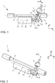
- Figure 1 shows a first embodiment of such a steering system 1 with a steering column 2, a rack 3, a steering pinion 4 that couples the steering column 2 to the rack 3, and an electric drive device 5, the drive torque of which is introduced into the steering 1 on the steering pinion 4.
- a torque measuring device 6 is arranged in the coupling area between the steering column 2 and the steering pinion 4.
- the steering pinion 4 is via two bearings 7 and 8 in one Figure 1 steering housing not shown rotatably mounted.
- the steering pinion 4 has a toothed section 9 which is in engagement with a toothing of the rack 3. Furthermore, in Figure 1 a pressure piece 10 is indicated, which presses the rack 3 against the toothed section 9 of the steering pinion 4.
- An axis of rotation A of the steering pinion 4 when installed on a motor vehicle, forms an angle ⁇ with an amount in the range from 0 to 40 ° in a vertical plane yz stretched from the vehicle transverse direction y and the vertical direction z to the vertical direction z.
- the axis of rotation A forms an angle with the vertical direction z with an amount in the range from 0 to 60 °.
- the electric drive device 5 comprises an electric motor 11 and a gear stage connected downstream of this with a worm shaft 12 and a worm wheel 13.
- the gear stage is preferably single-stage.
- the worm shaft 12 directly adjoins the electric motor 11.
- the worm shaft can be integrated into a motor output shaft.
- the worm shaft 12 can run coaxially to the axis of rotation D of the electric motor 11.
- the worm wheel 13 is arranged and fastened on the steering pinion 4.
- the axis of rotation B of the worm shaft 12 and the axis of rotation C of the worm wheel 13, which coincides with the axis of rotation A of the steering pinion 4, preferably enclose a crossing angle ⁇ in the range from 20 ° to 80 ° with one another.
- the worm wheel 13 lies on the side of the rack 3 opposite the steering column 2.
- the rack 3 is thus arranged between the worm wheel 13 of the electric drive device 5 and the steering column 2.
- the arrangement of the electric drive device 5 is not impaired by the torque measuring device 6. This increases the possibility of different positions of the electric drive device 5 relative to the rack 3. In addition, this results in a compact design.
- the electric drive device 5 is arranged in relation to the vertical direction z in the installation position below the rack 3.
- the worm wheel 13 and preferably also the electric motor 11 can be arranged below the rack 3 in relation to the vertical direction.
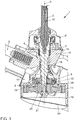
- the invention proceeds according to Figures 1 and 2 the axis of rotation D of the electric motor 11 parallel to the rack 3.
- the steering pinion 4 is rotatably supported by two bearings 7 and 8.
- the toothing forces of the gear stage are supported at the same time via these two bearings 7 and 8, so that no additional bearing is required for the worm wheel 13.
- the worm wheel 13 can be cantilevered on an end section 14 of the steering pinion 4, whereby the second bearing 8 is located between the toothed section 9 and the end section 14 of the steering pinion 4 to which the worm wheel 13 is attached.
- the toothed section 9 of the steering pinion 4 lies between the two bearings 7 and 8.
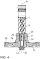
- FIG. 3 An example of a constructive implementation is in Figure 3 shown on the basis of a second embodiment. Components corresponding to the first exemplary embodiment are provided with the same reference numerals in the present case.
- a steering housing 15 in which the steering pinion 4 is supported via a first bearing 7, for example in the form of a needle bearing, and a second bearing 8, for example in the form of a ball bearing.
- the steering housing 15 forms a flange 16 for supporting the torque measuring device 6, into which the steering column 2 extends with an intermediate shaft and is coupled to the steering pinion 4 by means of a torsion bar 17.
- the electric drive device 5 acts on the end section 14 of the steering pinion 4 opposite the steering column 2.
- the worm wheel 13 is attached to this free end section 14.
- the steering housing 15 accordingly forms a pot-like receptacle 18 for the worm wheel 13 on its side opposite the flange 16.
- the pot-like receptacle 18 can be closed by a cover 19.
- the worm wheel 13 is pushed with a hub section 20 onto the end section 14 of the steering pinion 4 and secured axially on the latter by means of a securing element 21.
- An inner bearing ring 22 of the second bearing 8 is simultaneously fixed on the steering pinion 4 via this axial securing means.
- An outer bearing ring 23 of the second bearing 8 can be fixed in the steering housing 15 by means of a shaft locking ring 24, for example.
- a positive connection can be provided, for example in the form of a fitting toothing.
- a suitable preload can be applied with a suitable securing element 21.
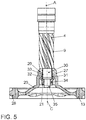
- Figure 4 shows a variant for fastening the worm wheel 13 to the steering pinion 4.
- a hub section 20 of the worm wheel 13 has a toothed section 25 on its inner circumference, which is pushed axially onto an external toothing 26 formed on the steering pinion 4.
- a fastening screw serves as the securing element 21, which is screwed into the end section 14 of the steering pinion 4 and braces the hub section 20 against a contact shoulder on the steering pinion 4.
- the hub section 20 can extend as far as the toothed section 9 of the steering pinion 4 and at the same time serve as the inner bearing ring of the second bearing 8, or it can form a section 27 for fastening such an inner bearing ring 22.
- a ring gear section 28 of the worm wheel 13 is connected to the hub section 20 via a connection section 29.
- Said sections 20, 28 and 29 of the worm wheel 13 can be made in one piece with one another. However, it is also possible to manufacture individual sections as separate components and to connect the latter to one another. As a result, different materials can be used for the individual sections 20, 28 and 29.
- Figure 5 shows a further embodiment for the attachment of the worm wheel 13 on the steering pinion 4 by means of a purely force-fit connection.
- the non-positive connection can be designed, for example, as a cone association.
- a cylindrical seat 30 can be formed on the end section of the steering pinion 4.
- the hub section 20 of the worm wheel 13 and a conical sleeve 31 are pushed onto this seat 30.
- the conical sleeve 31 is centered on the outer circumference of the seat 30 and has on its outer circumference a conical surface 32 which engages with a conical surface 33 on the inner circumference of the hub section 20.
- the two conical surfaces 32 and 33 are braced against one another by means of a securing element 21 in the form of a fastening nut 34 which is screwed onto a threaded section 35 at the end of the steering pinion 4.
- a fastening screw can also be used, just like in Figure 4 an axial securing by means of a fastening nut 34 is analogous Figure 5 is possible.
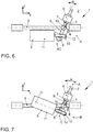
- Figure 6 shows, in the form of a third exemplary embodiment, a further possible modification of the electromechanical motor vehicle steering systems explained above.
- Components corresponding to the first and second exemplary embodiments are again provided with the same reference symbols in the present case.
- both the toothed section 9 of the steering pinion 4, which is in engagement with the rack 3, and the worm wheel 13 are arranged between the two bearings 7 and 8.
- the axis of rotation B of the worm shaft 12 and the axis of rotation C of the worm wheel 13 or axis of rotation A of the steering pinion 4 enclose a crossing angle ⁇ in the range from 20 ° to 80 ° with one another.
- Figure 7 shows within the scope of a fourth embodiment, which is not part of the invention, another
- the worm wheel 13 remains, however, arranged on the side of the rack 3 opposite the steering column 2.
- the worm wheel 13 is in this case between the toothed section 9 of the steering pinion 4 and the second bearing 8 on the end section 14 of the steering pinion 4.
- the axis of rotation D of the electric motor 11 is accordingly set at an angle other than zero to a horizontal plane xy.
Landscapes
- Engineering & Computer Science (AREA)
- Chemical & Material Sciences (AREA)
- Combustion & Propulsion (AREA)
- Transportation (AREA)
- Mechanical Engineering (AREA)
- Power Steering Mechanism (AREA)
- Connection Of Motors, Electrical Generators, Mechanical Devices, And The Like (AREA)
Claims (10)
- Direction électromécanique assistée de véhicule,
comprenant une colonne de direction (2),
une crémaillère (3),
un pignon de direction (4), couplant la colonne de direction (2) à la crémaillère (3) et un dispositif électrique d'entraînement (5) comprenant un moteur électrique (11) et une roue hélicoïdale (13), disposée sur le pignon de direction (4),
dans laquelle
la crémaillère (3) se trouve entre la roue hélicoïdale (13) du dispositif électrique d'entraînement
(5) et la colonne de direction (2),
caractérisée en ce que
le moteur électrique (11) présente un axe de rotation (D), qui s'étend parallèle à la crémaillère (3). - Direction électromécanique assistée de véhicule selon la revendication 1, caractérisée en ce que la roue hélicoïdale (13) est montée flottante sur une section d'extrémité (14) du pignon de direction (4).
- Direction électromécanique assistée de véhicule selon la revendication 1 ou 2, caractérisée en ce que le pignon de direction (4) est monté au moyen d'un premier palier (7) et d'un second palier (8) rotatif dans un boîtier de direction (15), dans lequel une section de denture (9) du pignon de direction (4), qui vient en prise avec la crémaillère (3), se trouve entre ces deux paliers (7, 8).
- Direction électromécanique assistée de véhicule selon la revendication 1, caractérisée en ce que le pignon de direction (4) est monté au moyen d'un premier palier (7) et d'un second palier (8) rotatif dans un boîtier de direction (15), dans lequel une section de denture (9) du pignon de direction (4), qui vient en prise avec la crémaillère (3) et la roue hélicoïdale (13), se trouvent entre ces deux paliers (7, 8).
- Direction électromécanique assistée de véhicule selon l'une quelconque des revendications 1 à 4, caractérisée en ce que le dispositif électrique d'entraînement (5) présente un arbre à vis sans fin (12), qui est accouplé au moteur électrique (11) par entraînement et vient en prise avec la roue hélicoïdale (13), dans lequel l'axe de rotation (B) de l'arbre à vis sans fin (12) et l'axe de rotation (A) de la roue hélicoïdale (13) forment ensemble un angle de croisement (β) dans la plage de 20° à 80°.
- Direction électromécanique assistée de véhicule selon l'une quelconque des revendications 1 à 4, caractérisée en ce que le dispositif électrique d'entraînement (5) présente un arbre à vis sans fin (12), qui est accouplé au moteur électrique (11) par entraînement et vient en prise avec la roue hélicoïdale (13), dans lequel l'axe de rotation (B) de l'arbre à vis sans fin (12) et l'axe de rotation (A) de la roue hélicoïdale (13) forment un angle de croisement (β) de 90°.
- Direction électromécanique assistée de véhicule selon l'une quelconque des revendications 1 à 6, caractérisée en ce que l'arbre à vis sans fin (12) s'étend coaxial à un axe de rotation (D) du moteur électrique (11).
- Direction électromécanique assistée de véhicule selon l'une quelconque des revendications 1 à 7, caractérisée en ce que la roue hélicoïdale (13) est disposée, par rapport à la direction verticale en position de montage de la direction de véhicule à moteur, sous la crémaillère (3).
- Direction électromécanique assistée de véhicule selon l'une quelconque des revendications 1 à 8, caractérisée en ce que le moteur électrique (11) est disposé, par rapport à la direction verticale en position de montage de la direction de véhicule à moteur, sous la crémaillère (3).
- Direction électromécanique assistée de véhicule selon l'une quelconque des revendications 1 à 9, caractérisée en ce que la roue hélicoïdale (13) est fixée par verrouillage mécanique au pignon de direction (4) et la liaison est conçue de manière à glisser en cas de dépassement d'un couple prédéfini, afin d'offrir une protection contre les surcharges.
Applications Claiming Priority (2)
| Application Number | Priority Date | Filing Date | Title |
|---|---|---|---|
| DE102017208248.8A DE102017208248A1 (de) | 2017-05-16 | 2017-05-16 | Elektromechanische Kraftfahrzeuglenkung |
| PCT/EP2018/058931 WO2018210486A1 (fr) | 2017-05-16 | 2018-04-06 | Direction électromécanique de véhicule à moteur |
Publications (2)
| Publication Number | Publication Date |
|---|---|
| EP3625110A1 EP3625110A1 (fr) | 2020-03-25 |
| EP3625110B1 true EP3625110B1 (fr) | 2021-07-21 |
Family
ID=61972514
Family Applications (1)
| Application Number | Title | Priority Date | Filing Date |
|---|---|---|---|
| EP18717886.8A Active EP3625110B1 (fr) | 2017-05-16 | 2018-04-06 | Direction électromécanique assistée de véhicule |
Country Status (5)
| Country | Link |
|---|---|
| US (1) | US11407444B2 (fr) |
| EP (1) | EP3625110B1 (fr) |
| CN (1) | CN110612244B (fr) |
| DE (1) | DE102017208248A1 (fr) |
| WO (1) | WO2018210486A1 (fr) |
Families Citing this family (4)
| Publication number | Priority date | Publication date | Assignee | Title |
|---|---|---|---|---|
| JP6968272B2 (ja) * | 2018-05-22 | 2021-11-17 | 三菱電機株式会社 | 電動パワーステアリング装置 |
| DE102018212607A1 (de) * | 2018-07-27 | 2020-01-30 | Volkswagen Aktiengesellschaft | Elektromechanische Kraftfahrzeuglenkung, Montageverfahren dazu sowie Fahrzeug mit einer solchen Kraftfahrzeuglenkung |
| DE102018221000A1 (de) | 2018-12-05 | 2020-06-10 | Volkswagen Aktiengesellschaft | Elektromechanische Kraftfahrzeuglenkung sowie Kraftfahrzeug mit einer derartigen Kraftfahrzeuglenkung |
| US12420857B1 (en) * | 2024-03-21 | 2025-09-23 | Thyssenkrupp Presta Ag | Steering wheel interface with cone for steering wheel adjustment |
Family Cites Families (20)
| Publication number | Priority date | Publication date | Assignee | Title |
|---|---|---|---|---|
| DE19811784A1 (de) | 1998-03-18 | 1999-09-23 | Mannesmann Vdo Ag | Elektrische Lenkhilfe |
| DE10142388B4 (de) | 2000-11-22 | 2018-01-04 | Volkswagen Ag | Hilfsrahmenanordnung für ein Kraftfahrzeug und Kraftfahrzeug |
| JP2004074831A (ja) | 2002-08-09 | 2004-03-11 | Honda Motor Co Ltd | 電動パワーステアリング装置 |
| JP4389616B2 (ja) * | 2004-03-15 | 2009-12-24 | 日本精工株式会社 | 電動式パワーステアリング装置 |
| DE102007004218A1 (de) | 2007-01-27 | 2008-09-04 | Zf Lenksysteme Gmbh | Hilfskraftlenkung |
| JP5016451B2 (ja) * | 2007-11-16 | 2012-09-05 | カヤバ工業株式会社 | パワーステアリング装置及びその製造方法 |
| DE102009027468A1 (de) | 2009-07-06 | 2011-01-13 | Robert Bosch Gmbh | Kraftübertragungsanordnung |
| DE102010027553B4 (de) | 2010-07-19 | 2015-05-28 | Thyssenkrupp Presta Aktiengesellschaft | Lenkgetriebe mit Doppelritzel |
| EP2578470A1 (fr) | 2011-02-24 | 2013-04-10 | Showa Corporation | Appareil de direction assistée commandé par moteur |
| JP2013071679A (ja) | 2011-09-28 | 2013-04-22 | Showa Corp | 電動パワーステアリング装置 |
| JP5829133B2 (ja) * | 2012-01-13 | 2015-12-09 | 日立オートモティブシステムズステアリング株式会社 | パワーステアリング装置 |
| DE102012021436A1 (de) | 2012-10-30 | 2014-04-30 | Volkswagen Aktiengesellschaft | Vorrichtung zum assistierenden oder automatischen Führen eines Kraftfahrzeuges |
| CN104918839A (zh) * | 2013-01-24 | 2015-09-16 | 丰田自动车株式会社 | 电动动力转向装置 |
| US9643476B2 (en) | 2014-03-06 | 2017-05-09 | Intro-Tech Automotive, Inc. | Durable folding automobile sunshade and method of manufacturing same |
| JP6305799B2 (ja) | 2014-03-19 | 2018-04-04 | 日立オートモティブシステムズ株式会社 | パワーステアリング装置 |
| JP6129774B2 (ja) | 2014-03-24 | 2017-05-17 | 株式会社ショーワ | パワーステアリング装置 |
| JP6420184B2 (ja) * | 2015-03-06 | 2018-11-07 | トヨタ自動車株式会社 | 電動パワーステアリング装置 |
| JP6535969B2 (ja) * | 2015-03-26 | 2019-07-03 | 日立オートモティブシステムズ株式会社 | 電動パワーステアリング装置 |
| CN104818839A (zh) | 2015-05-11 | 2015-08-05 | 江苏省华建建设股份有限公司 | 一种提升式脚手架防坠落装置 |
| DE102016013272A1 (de) * | 2016-11-09 | 2018-05-09 | Thyssenkrupp Ag | Verfahren zur vereinfachten Montage eines Zahnstangenlenkgetriebes einer Zahnstangenlenkung |
-
2017
- 2017-05-16 DE DE102017208248.8A patent/DE102017208248A1/de active Pending
-
2018
- 2018-04-06 EP EP18717886.8A patent/EP3625110B1/fr active Active
- 2018-04-06 WO PCT/EP2018/058931 patent/WO2018210486A1/fr not_active Ceased
- 2018-04-06 CN CN201880032976.3A patent/CN110612244B/zh active Active
- 2018-04-06 US US16/614,448 patent/US11407444B2/en active Active
Also Published As
| Publication number | Publication date |
|---|---|
| US20200198691A1 (en) | 2020-06-25 |
| US11407444B2 (en) | 2022-08-09 |
| EP3625110A1 (fr) | 2020-03-25 |
| DE102017208248A1 (de) | 2018-11-22 |
| CN110612244A (zh) | 2019-12-24 |
| WO2018210486A1 (fr) | 2018-11-22 |
| CN110612244B (zh) | 2022-09-13 |
Similar Documents
| Publication | Publication Date | Title |
|---|---|---|
| EP3625110B1 (fr) | Direction électromécanique assistée de véhicule | |
| EP3148860B1 (fr) | Arbre de direction d'un véhicule automobile | |
| DE102008036730A1 (de) | Aktuatoreinheit für eine Kraftfahrzeug-Steer-by-Wire-Lenkeinrichtung | |
| EP1237777B1 (fr) | Dispositif de direction pour vehicules automobiles | |
| DE102009028386A1 (de) | Vorrichtung zum Variieren eines Wankwinkels einer Fahrzeugkarosserie im Bereich wenigstens einer Fahrzeugachse | |
| EP1223073B1 (fr) | Unité transmission-entraînement pour le réglage d'un siège ou une direction assistée, avec au moins un élément de support | |
| DE19861276B4 (de) | Spindel- oder Schneckenantrieb für Verstelleinrichtungen in Kraftfahrzeugen | |
| DE102018100318B4 (de) | Lenksäule für ein fahrzeug | |
| DE102006029283B4 (de) | Lenkantrieb für Flurförderfahrzeug | |
| WO2019068493A1 (fr) | Mécanisme de direction et procédé pour assembler un engin de direction pour un véhicule automobile | |
| DE102015215428B4 (de) | Antriebseinrichtung für einen Komfortantrieb eines Kraftfahrzeugs und Komfortantrieb | |
| DE102007024328A1 (de) | Elektromechanische Lenkung mit einem koaxialen Motor | |
| DE102012011601A1 (de) | Verzwängungsfreies Befestigungssystem, insbesondere zur Befestigung von Lenkgetriebegehäusen | |
| WO2020048668A1 (fr) | Direction électromécanique de véhicule | |
| DE102010017851A1 (de) | Torsionsmodul | |
| DE102018215188A1 (de) | Elektromechanische Fahrzeuglenkung | |
| EP2562058B1 (fr) | Dispositif d'appui monté de manière modulaire pour un semi-remorque et semi-remorque doté d'un tel dispositif d'appui | |
| DE102011017335A1 (de) | Fahrzeuglenkung mit Verriegelungsscheibe und Lagesensor | |
| EP3523160B1 (fr) | Agencement de transmission pour mécanisme d'entraînement de broche, entraînement de broche et siège de véhicule | |
| DE102015211629A1 (de) | Hinterachslenkung für ein Kraftfahrzeug | |
| DE102021208151A1 (de) | Lenksäule für ein Steer-by-wire-Lenksystem eines Kraftfahrzeugs | |
| DE19861278C5 (de) | Spindel- oder Schneckenantrieb für Verstelleinrichtungen in Kraftfahrzeugen | |
| DE102011051529A1 (de) | Lenkgetriebe mit einer mechanischen begrenzung des abtriebswellenwinkels für schwere nutzkraftwagen mit elektrischer lenkunterstützung | |
| WO2023052045A1 (fr) | Dispositif d'entraînement pour un mécanisme d'ouverture destiné à ouvrir un élément d'ouverture mobile d'un véhicule, et système d'ouverture pour un véhicule | |
| DE102016212812A1 (de) | Lenkung für ein Kraftfahrzeug, insbesondere für ein Nutzfahrzeug, mit Lenkwelle und Kugelgewindemutter |
Legal Events
| Date | Code | Title | Description |
|---|---|---|---|
| STAA | Information on the status of an ep patent application or granted ep patent |
Free format text: STATUS: UNKNOWN |
|
| STAA | Information on the status of an ep patent application or granted ep patent |
Free format text: STATUS: THE INTERNATIONAL PUBLICATION HAS BEEN MADE |
|
| PUAI | Public reference made under article 153(3) epc to a published international application that has entered the european phase |
Free format text: ORIGINAL CODE: 0009012 |
|
| STAA | Information on the status of an ep patent application or granted ep patent |
Free format text: STATUS: REQUEST FOR EXAMINATION WAS MADE |
|
| 17P | Request for examination filed |
Effective date: 20191216 |
|
| AK | Designated contracting states |
Kind code of ref document: A1 Designated state(s): AL AT BE BG CH CY CZ DE DK EE ES FI FR GB GR HR HU IE IS IT LI LT LU LV MC MK MT NL NO PL PT RO RS SE SI SK SM TR |
|
| AX | Request for extension of the european patent |
Extension state: BA ME |
|
| DAV | Request for validation of the european patent (deleted) | ||
| DAX | Request for extension of the european patent (deleted) | ||
| GRAP | Despatch of communication of intention to grant a patent |
Free format text: ORIGINAL CODE: EPIDOSNIGR1 |
|
| STAA | Information on the status of an ep patent application or granted ep patent |
Free format text: STATUS: GRANT OF PATENT IS INTENDED |
|
| INTG | Intention to grant announced |
Effective date: 20210326 |
|
| RIN1 | Information on inventor provided before grant (corrected) |
Inventor name: KNOPP, THOMAS Inventor name: THIES, JOACHIM Inventor name: JENKE, KLAAS-SIMON |
|
| GRAS | Grant fee paid |
Free format text: ORIGINAL CODE: EPIDOSNIGR3 |
|
| GRAA | (expected) grant |
Free format text: ORIGINAL CODE: 0009210 |
|
| STAA | Information on the status of an ep patent application or granted ep patent |
Free format text: STATUS: THE PATENT HAS BEEN GRANTED |
|
| AK | Designated contracting states |
Kind code of ref document: B1 Designated state(s): AL AT BE BG CH CY CZ DE DK EE ES FI FR GB GR HR HU IE IS IT LI LT LU LV MC MK MT NL NO PL PT RO RS SE SI SK SM TR |
|
| REG | Reference to a national code |
Ref country code: GB Ref legal event code: FG4D Free format text: NOT ENGLISH |
|
| REG | Reference to a national code |
Ref country code: CH Ref legal event code: EP |
|
| REG | Reference to a national code |
Ref country code: DE Ref legal event code: R096 Ref document number: 502018006218 Country of ref document: DE |
|
| REG | Reference to a national code |
Ref country code: AT Ref legal event code: REF Ref document number: 1412362 Country of ref document: AT Kind code of ref document: T Effective date: 20210815 |
|
| REG | Reference to a national code |
Ref country code: IE Ref legal event code: FG4D Free format text: LANGUAGE OF EP DOCUMENT: GERMAN |
|
| REG | Reference to a national code |
Ref country code: LT Ref legal event code: MG9D |
|
| REG | Reference to a national code |
Ref country code: NL Ref legal event code: MP Effective date: 20210721 |
|
| PG25 | Lapsed in a contracting state [announced via postgrant information from national office to epo] |
Ref country code: HR Free format text: LAPSE BECAUSE OF FAILURE TO SUBMIT A TRANSLATION OF THE DESCRIPTION OR TO PAY THE FEE WITHIN THE PRESCRIBED TIME-LIMIT Effective date: 20210721 Ref country code: ES Free format text: LAPSE BECAUSE OF FAILURE TO SUBMIT A TRANSLATION OF THE DESCRIPTION OR TO PAY THE FEE WITHIN THE PRESCRIBED TIME-LIMIT Effective date: 20210721 Ref country code: FI Free format text: LAPSE BECAUSE OF FAILURE TO SUBMIT A TRANSLATION OF THE DESCRIPTION OR TO PAY THE FEE WITHIN THE PRESCRIBED TIME-LIMIT Effective date: 20210721 Ref country code: SE Free format text: LAPSE BECAUSE OF FAILURE TO SUBMIT A TRANSLATION OF THE DESCRIPTION OR TO PAY THE FEE WITHIN THE PRESCRIBED TIME-LIMIT Effective date: 20210721 Ref country code: RS Free format text: LAPSE BECAUSE OF FAILURE TO SUBMIT A TRANSLATION OF THE DESCRIPTION OR TO PAY THE FEE WITHIN THE PRESCRIBED TIME-LIMIT Effective date: 20210721 Ref country code: LT Free format text: LAPSE BECAUSE OF FAILURE TO SUBMIT A TRANSLATION OF THE DESCRIPTION OR TO PAY THE FEE WITHIN THE PRESCRIBED TIME-LIMIT Effective date: 20210721 Ref country code: BG Free format text: LAPSE BECAUSE OF FAILURE TO SUBMIT A TRANSLATION OF THE DESCRIPTION OR TO PAY THE FEE WITHIN THE PRESCRIBED TIME-LIMIT Effective date: 20211021 Ref country code: PT Free format text: LAPSE BECAUSE OF FAILURE TO SUBMIT A TRANSLATION OF THE DESCRIPTION OR TO PAY THE FEE WITHIN THE PRESCRIBED TIME-LIMIT Effective date: 20211122 Ref country code: NL Free format text: LAPSE BECAUSE OF FAILURE TO SUBMIT A TRANSLATION OF THE DESCRIPTION OR TO PAY THE FEE WITHIN THE PRESCRIBED TIME-LIMIT Effective date: 20210721 Ref country code: NO Free format text: LAPSE BECAUSE OF FAILURE TO SUBMIT A TRANSLATION OF THE DESCRIPTION OR TO PAY THE FEE WITHIN THE PRESCRIBED TIME-LIMIT Effective date: 20211021 |
|
| PG25 | Lapsed in a contracting state [announced via postgrant information from national office to epo] |
Ref country code: PL Free format text: LAPSE BECAUSE OF FAILURE TO SUBMIT A TRANSLATION OF THE DESCRIPTION OR TO PAY THE FEE WITHIN THE PRESCRIBED TIME-LIMIT Effective date: 20210721 Ref country code: LV Free format text: LAPSE BECAUSE OF FAILURE TO SUBMIT A TRANSLATION OF THE DESCRIPTION OR TO PAY THE FEE WITHIN THE PRESCRIBED TIME-LIMIT Effective date: 20210721 Ref country code: GR Free format text: LAPSE BECAUSE OF FAILURE TO SUBMIT A TRANSLATION OF THE DESCRIPTION OR TO PAY THE FEE WITHIN THE PRESCRIBED TIME-LIMIT Effective date: 20211022 |
|
| REG | Reference to a national code |
Ref country code: DE Ref legal event code: R097 Ref document number: 502018006218 Country of ref document: DE |
|
| PG25 | Lapsed in a contracting state [announced via postgrant information from national office to epo] |
Ref country code: DK Free format text: LAPSE BECAUSE OF FAILURE TO SUBMIT A TRANSLATION OF THE DESCRIPTION OR TO PAY THE FEE WITHIN THE PRESCRIBED TIME-LIMIT Effective date: 20210721 |
|
| PLBE | No opposition filed within time limit |
Free format text: ORIGINAL CODE: 0009261 |
|
| STAA | Information on the status of an ep patent application or granted ep patent |
Free format text: STATUS: NO OPPOSITION FILED WITHIN TIME LIMIT |
|
| PG25 | Lapsed in a contracting state [announced via postgrant information from national office to epo] |
Ref country code: SM Free format text: LAPSE BECAUSE OF FAILURE TO SUBMIT A TRANSLATION OF THE DESCRIPTION OR TO PAY THE FEE WITHIN THE PRESCRIBED TIME-LIMIT Effective date: 20210721 Ref country code: SK Free format text: LAPSE BECAUSE OF FAILURE TO SUBMIT A TRANSLATION OF THE DESCRIPTION OR TO PAY THE FEE WITHIN THE PRESCRIBED TIME-LIMIT Effective date: 20210721 Ref country code: RO Free format text: LAPSE BECAUSE OF FAILURE TO SUBMIT A TRANSLATION OF THE DESCRIPTION OR TO PAY THE FEE WITHIN THE PRESCRIBED TIME-LIMIT Effective date: 20210721 Ref country code: EE Free format text: LAPSE BECAUSE OF FAILURE TO SUBMIT A TRANSLATION OF THE DESCRIPTION OR TO PAY THE FEE WITHIN THE PRESCRIBED TIME-LIMIT Effective date: 20210721 Ref country code: CZ Free format text: LAPSE BECAUSE OF FAILURE TO SUBMIT A TRANSLATION OF THE DESCRIPTION OR TO PAY THE FEE WITHIN THE PRESCRIBED TIME-LIMIT Effective date: 20210721 Ref country code: AL Free format text: LAPSE BECAUSE OF FAILURE TO SUBMIT A TRANSLATION OF THE DESCRIPTION OR TO PAY THE FEE WITHIN THE PRESCRIBED TIME-LIMIT Effective date: 20210721 |
|
| 26N | No opposition filed |
Effective date: 20220422 |
|
| PG25 | Lapsed in a contracting state [announced via postgrant information from national office to epo] |
Ref country code: IT Free format text: LAPSE BECAUSE OF FAILURE TO SUBMIT A TRANSLATION OF THE DESCRIPTION OR TO PAY THE FEE WITHIN THE PRESCRIBED TIME-LIMIT Effective date: 20210721 |
|
| REG | Reference to a national code |
Ref country code: CH Ref legal event code: PL |
|
| REG | Reference to a national code |
Ref country code: BE Ref legal event code: MM Effective date: 20220430 |
|
| PG25 | Lapsed in a contracting state [announced via postgrant information from national office to epo] |
Ref country code: MC Free format text: LAPSE BECAUSE OF FAILURE TO SUBMIT A TRANSLATION OF THE DESCRIPTION OR TO PAY THE FEE WITHIN THE PRESCRIBED TIME-LIMIT Effective date: 20210721 Ref country code: LU Free format text: LAPSE BECAUSE OF NON-PAYMENT OF DUE FEES Effective date: 20220406 Ref country code: LI Free format text: LAPSE BECAUSE OF NON-PAYMENT OF DUE FEES Effective date: 20220430 Ref country code: CH Free format text: LAPSE BECAUSE OF NON-PAYMENT OF DUE FEES Effective date: 20220430 |
|
| PG25 | Lapsed in a contracting state [announced via postgrant information from national office to epo] |
Ref country code: BE Free format text: LAPSE BECAUSE OF NON-PAYMENT OF DUE FEES Effective date: 20220430 |
|
| PG25 | Lapsed in a contracting state [announced via postgrant information from national office to epo] |
Ref country code: IE Free format text: LAPSE BECAUSE OF NON-PAYMENT OF DUE FEES Effective date: 20220406 |
|
| P01 | Opt-out of the competence of the unified patent court (upc) registered |
Effective date: 20230523 |
|
| PG25 | Lapsed in a contracting state [announced via postgrant information from national office to epo] |
Ref country code: MK Free format text: LAPSE BECAUSE OF FAILURE TO SUBMIT A TRANSLATION OF THE DESCRIPTION OR TO PAY THE FEE WITHIN THE PRESCRIBED TIME-LIMIT Effective date: 20210721 Ref country code: CY Free format text: LAPSE BECAUSE OF FAILURE TO SUBMIT A TRANSLATION OF THE DESCRIPTION OR TO PAY THE FEE WITHIN THE PRESCRIBED TIME-LIMIT Effective date: 20210721 |
|
| PG25 | Lapsed in a contracting state [announced via postgrant information from national office to epo] |
Ref country code: HU Free format text: LAPSE BECAUSE OF FAILURE TO SUBMIT A TRANSLATION OF THE DESCRIPTION OR TO PAY THE FEE WITHIN THE PRESCRIBED TIME-LIMIT; INVALID AB INITIO Effective date: 20180406 |
|
| REG | Reference to a national code |
Ref country code: AT Ref legal event code: MM01 Ref document number: 1412362 Country of ref document: AT Kind code of ref document: T Effective date: 20230406 |
|
| PG25 | Lapsed in a contracting state [announced via postgrant information from national office to epo] |
Ref country code: TR Free format text: LAPSE BECAUSE OF FAILURE TO SUBMIT A TRANSLATION OF THE DESCRIPTION OR TO PAY THE FEE WITHIN THE PRESCRIBED TIME-LIMIT Effective date: 20210721 |
|
| PG25 | Lapsed in a contracting state [announced via postgrant information from national office to epo] |
Ref country code: AT Free format text: LAPSE BECAUSE OF NON-PAYMENT OF DUE FEES Effective date: 20230406 |
|
| PG25 | Lapsed in a contracting state [announced via postgrant information from national office to epo] |
Ref country code: AT Free format text: LAPSE BECAUSE OF NON-PAYMENT OF DUE FEES Effective date: 20230406 |
|
| PG25 | Lapsed in a contracting state [announced via postgrant information from national office to epo] |
Ref country code: MT Free format text: LAPSE BECAUSE OF FAILURE TO SUBMIT A TRANSLATION OF THE DESCRIPTION OR TO PAY THE FEE WITHIN THE PRESCRIBED TIME-LIMIT Effective date: 20210721 |
|
| PGFP | Annual fee paid to national office [announced via postgrant information from national office to epo] |
Ref country code: DE Payment date: 20250430 Year of fee payment: 8 |
|
| PGFP | Annual fee paid to national office [announced via postgrant information from national office to epo] |
Ref country code: GB Payment date: 20250422 Year of fee payment: 8 |
|
| PGFP | Annual fee paid to national office [announced via postgrant information from national office to epo] |
Ref country code: FR Payment date: 20250424 Year of fee payment: 8 |
|
| PGFP | Annual fee paid to national office [announced via postgrant information from national office to epo] |
Ref country code: AT Payment date: 20260410 Year of fee payment: 5 |