EP3625155B1 - Poulies de transporteur d'arbre de liaison - Google Patents
Poulies de transporteur d'arbre de liaison Download PDFInfo
- Publication number
- EP3625155B1 EP3625155B1 EP18802574.6A EP18802574A EP3625155B1 EP 3625155 B1 EP3625155 B1 EP 3625155B1 EP 18802574 A EP18802574 A EP 18802574A EP 3625155 B1 EP3625155 B1 EP 3625155B1
- Authority
- EP
- European Patent Office
- Prior art keywords
- bearing
- stub shaft
- center tube
- pulley
- conveyor
- Prior art date
- Legal status (The legal status is an assumption and is not a legal conclusion. Google has not performed a legal analysis and makes no representation as to the accuracy of the status listed.)
- Not-in-force
Links
Images

Classifications
-
- B—PERFORMING OPERATIONS; TRANSPORTING
- B65—CONVEYING; PACKING; STORING; HANDLING THIN OR FILAMENTARY MATERIAL
- B65G—TRANSPORT OR STORAGE DEVICES, e.g. CONVEYORS FOR LOADING OR TIPPING, SHOP CONVEYOR SYSTEMS OR PNEUMATIC TUBE CONVEYORS
- B65G39/00—Rollers, e.g. drive rollers, or arrangements thereof incorporated in roller-ways or other types of mechanical conveyors
- B65G39/02—Adaptations of individual rollers and supports therefor
- B65G39/09—Arrangements of bearing or sealing means
-
- F—MECHANICAL ENGINEERING; LIGHTING; HEATING; WEAPONS; BLASTING
- F16—ENGINEERING ELEMENTS AND UNITS; GENERAL MEASURES FOR PRODUCING AND MAINTAINING EFFECTIVE FUNCTIONING OF MACHINES OR INSTALLATIONS; THERMAL INSULATION IN GENERAL
- F16C—SHAFTS; FLEXIBLE SHAFTS; ELEMENTS OR CRANKSHAFT MECHANISMS; ROTARY BODIES OTHER THAN GEARING ELEMENTS; BEARINGS
- F16C19/00—Bearings with rolling contact, for exclusively rotary movement
- F16C19/54—Systems consisting of a plurality of bearings with rolling friction
- F16C19/56—Systems consisting of a plurality of bearings with rolling friction in which the rolling bodies of one bearing differ in diameter from those of another
-
- F—MECHANICAL ENGINEERING; LIGHTING; HEATING; WEAPONS; BLASTING
- F16—ENGINEERING ELEMENTS AND UNITS; GENERAL MEASURES FOR PRODUCING AND MAINTAINING EFFECTIVE FUNCTIONING OF MACHINES OR INSTALLATIONS; THERMAL INSULATION IN GENERAL
- F16C—SHAFTS; FLEXIBLE SHAFTS; ELEMENTS OR CRANKSHAFT MECHANISMS; ROTARY BODIES OTHER THAN GEARING ELEMENTS; BEARINGS
- F16C13/00—Rolls, drums, discs, or the like; Bearings or mountings therefor
- F16C13/02—Bearings
- F16C13/022—Bearings supporting a hollow roll mantle rotating with respect to a yoke or axle
-
- F—MECHANICAL ENGINEERING; LIGHTING; HEATING; WEAPONS; BLASTING
- F16—ENGINEERING ELEMENTS AND UNITS; GENERAL MEASURES FOR PRODUCING AND MAINTAINING EFFECTIVE FUNCTIONING OF MACHINES OR INSTALLATIONS; THERMAL INSULATION IN GENERAL
- F16C—SHAFTS; FLEXIBLE SHAFTS; ELEMENTS OR CRANKSHAFT MECHANISMS; ROTARY BODIES OTHER THAN GEARING ELEMENTS; BEARINGS
- F16C19/00—Bearings with rolling contact, for exclusively rotary movement
- F16C19/54—Systems consisting of a plurality of bearings with rolling friction
- F16C19/546—Systems with spaced apart rolling bearings including at least one angular contact bearing
-
- F—MECHANICAL ENGINEERING; LIGHTING; HEATING; WEAPONS; BLASTING
- F16—ENGINEERING ELEMENTS AND UNITS; GENERAL MEASURES FOR PRODUCING AND MAINTAINING EFFECTIVE FUNCTIONING OF MACHINES OR INSTALLATIONS; THERMAL INSULATION IN GENERAL
- F16C—SHAFTS; FLEXIBLE SHAFTS; ELEMENTS OR CRANKSHAFT MECHANISMS; ROTARY BODIES OTHER THAN GEARING ELEMENTS; BEARINGS
- F16C19/00—Bearings with rolling contact, for exclusively rotary movement
- F16C19/54—Systems consisting of a plurality of bearings with rolling friction
- F16C19/546—Systems with spaced apart rolling bearings including at least one angular contact bearing
- F16C19/547—Systems with spaced apart rolling bearings including at least one angular contact bearing with two angular contact rolling bearings
-
- F—MECHANICAL ENGINEERING; LIGHTING; HEATING; WEAPONS; BLASTING
- F16—ENGINEERING ELEMENTS AND UNITS; GENERAL MEASURES FOR PRODUCING AND MAINTAINING EFFECTIVE FUNCTIONING OF MACHINES OR INSTALLATIONS; THERMAL INSULATION IN GENERAL
- F16C—SHAFTS; FLEXIBLE SHAFTS; ELEMENTS OR CRANKSHAFT MECHANISMS; ROTARY BODIES OTHER THAN GEARING ELEMENTS; BEARINGS
- F16C19/00—Bearings with rolling contact, for exclusively rotary movement
- F16C19/54—Systems consisting of a plurality of bearings with rolling friction
- F16C19/546—Systems with spaced apart rolling bearings including at least one angular contact bearing
- F16C19/547—Systems with spaced apart rolling bearings including at least one angular contact bearing with two angular contact rolling bearings
- F16C19/548—Systems with spaced apart rolling bearings including at least one angular contact bearing with two angular contact rolling bearings in O-arrangement
-
- F—MECHANICAL ENGINEERING; LIGHTING; HEATING; WEAPONS; BLASTING
- F16—ENGINEERING ELEMENTS AND UNITS; GENERAL MEASURES FOR PRODUCING AND MAINTAINING EFFECTIVE FUNCTIONING OF MACHINES OR INSTALLATIONS; THERMAL INSULATION IN GENERAL
- F16C—SHAFTS; FLEXIBLE SHAFTS; ELEMENTS OR CRANKSHAFT MECHANISMS; ROTARY BODIES OTHER THAN GEARING ELEMENTS; BEARINGS
- F16C19/00—Bearings with rolling contact, for exclusively rotary movement
- F16C19/02—Bearings with rolling contact, for exclusively rotary movement with bearing balls essentially of the same size in one or more circular rows
- F16C19/14—Bearings with rolling contact, for exclusively rotary movement with bearing balls essentially of the same size in one or more circular rows for both radial and axial load
- F16C19/16—Bearings with rolling contact, for exclusively rotary movement with bearing balls essentially of the same size in one or more circular rows for both radial and axial load with a single row of balls
- F16C19/163—Bearings with rolling contact, for exclusively rotary movement with bearing balls essentially of the same size in one or more circular rows for both radial and axial load with a single row of balls with angular contact
-
- F—MECHANICAL ENGINEERING; LIGHTING; HEATING; WEAPONS; BLASTING
- F16—ENGINEERING ELEMENTS AND UNITS; GENERAL MEASURES FOR PRODUCING AND MAINTAINING EFFECTIVE FUNCTIONING OF MACHINES OR INSTALLATIONS; THERMAL INSULATION IN GENERAL
- F16C—SHAFTS; FLEXIBLE SHAFTS; ELEMENTS OR CRANKSHAFT MECHANISMS; ROTARY BODIES OTHER THAN GEARING ELEMENTS; BEARINGS
- F16C19/00—Bearings with rolling contact, for exclusively rotary movement
- F16C19/22—Bearings with rolling contact, for exclusively rotary movement with bearing rollers essentially of the same size in one or more circular rows, e.g. needle bearings
- F16C19/34—Bearings with rolling contact, for exclusively rotary movement with bearing rollers essentially of the same size in one or more circular rows, e.g. needle bearings for both radial and axial load
- F16C19/36—Bearings with rolling contact, for exclusively rotary movement with bearing rollers essentially of the same size in one or more circular rows, e.g. needle bearings for both radial and axial load with a single row of rollers
- F16C19/364—Bearings with rolling contact, for exclusively rotary movement with bearing rollers essentially of the same size in one or more circular rows, e.g. needle bearings for both radial and axial load with a single row of rollers with tapered rollers, i.e. rollers having essentially the shape of a truncated cone
-
- F—MECHANICAL ENGINEERING; LIGHTING; HEATING; WEAPONS; BLASTING
- F16—ENGINEERING ELEMENTS AND UNITS; GENERAL MEASURES FOR PRODUCING AND MAINTAINING EFFECTIVE FUNCTIONING OF MACHINES OR INSTALLATIONS; THERMAL INSULATION IN GENERAL
- F16C—SHAFTS; FLEXIBLE SHAFTS; ELEMENTS OR CRANKSHAFT MECHANISMS; ROTARY BODIES OTHER THAN GEARING ELEMENTS; BEARINGS
- F16C2240/00—Specified values or numerical ranges of parameters; Relations between them
- F16C2240/12—Force, load, stress, pressure
-
- F—MECHANICAL ENGINEERING; LIGHTING; HEATING; WEAPONS; BLASTING
- F16—ENGINEERING ELEMENTS AND UNITS; GENERAL MEASURES FOR PRODUCING AND MAINTAINING EFFECTIVE FUNCTIONING OF MACHINES OR INSTALLATIONS; THERMAL INSULATION IN GENERAL
- F16C—SHAFTS; FLEXIBLE SHAFTS; ELEMENTS OR CRANKSHAFT MECHANISMS; ROTARY BODIES OTHER THAN GEARING ELEMENTS; BEARINGS
- F16C2326/00—Articles relating to transporting
- F16C2326/58—Conveyor systems, e.g. rollers or bearings therefor
Definitions
- the field of the disclosure relates to stub shaft conveyor pulleys and, in particular, conveyor pulleys that may be used as a tail pulley and/or head pulley in a belt conveyor system.
- Unit handling operations involve transport of articles over conveyor systems to allow the articles to be processed.
- the contour of the head and tail pulleys of the conveyors creates a gap over which the article passes.
- the articles may shift as the articles pass over this gap. This may allow identifying information of the articles such as barcodes to change their orientation on the conveyor system which may cause the information to not be read. Further, the gap may allow packages to be jammed at the transition region.
- the gap between conveyor belts may be reduced by using relatively small-diameter pulleys.
- Smaller diameter pulleys are generally not suited for use with heavyrated bearings (e.g., heavy ball bearings) due to the smaller size and load capacity of the bearings.
- the smaller diameter also limits shaft size, which increases shaft deflection. This often results in frequent pulley failures. Such failures are costly and require significant downtime which is very detrimental in various unit handling operations (e.g., package handling).
- Bearings which may accommodate shaft deflection e.g., self-aligning bearings
- US 2005/217967 A1 discloses a conveyor roller assembly, a conveyor roller insert and an axle for conveyor roller.
- the conveyor pulley comprises a center tube having a first end and a second end; a first stub shaft assembly, the first stub shaft assembly being connected to the center tube at its first end; and a second stub shaft assembly, the second stub shaft assembly being connected to the center tube at its second end, the first and second stub shaft assemblies each comprising:an inner bearing, the inner bearing being an angular contact bearing and having a bore diameter (Dl);an outer bearing, the outer bearing being an angular contact bearing and having a bore diameter (D2) different than the inner bearing bore diameter; anda stub shaft received in the inner bearing and the outer bearing, wherein the first and second stub shaft assemblies each further comprise:a stub shaft assembly housing, the housing comprising:a main body portion; anda stem portion that extends from the main body portion that is received in the center tube.
- the pulley includes a center tube having a first end and a second end.
- the pulley includes first and second stub shaft assemblies.
- the first stub shaft assembly is partially received in the center tube at its first end.
- the second stub shaft assembly is partially received in the center tube at its second end.
- the first and second stub shaft assemblies each include an inboard bearing within the center tube.
- An outboard bearing is exterior to the center tube.
- a stub shaft is received in the inboard bearing assembly and the outboard bearing.
- the conveyor pulley includes a center tube having a first end and a second end.
- the pulley includes first and second stub shaft assemblies.
- the first stub shaft assembly is connected to the center tube at its first end.
- the second stub shaft assembly is connected to the center tube at its second end.
- the first and second stub shaft assemblies each have an outer end and include an outer bearing having an effective load center.
- the first and second stub shaft assemblies each include an inner bearing having an effective load center.
- the ratio of D i to D o is at least about 1.5:1.
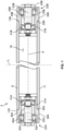
- Figure 1 is a front cross-section view of an example conveyor pulley 5.
- the conveyor pulley 5 includes a center tube 9 that has a first end 13A and a second end 13B.
- the center tube 9 defines a center tube chamber 19 within the center tube 9.
- the center tube 9 has an outer surface 11 which contacts the belt 610 ( Fig. 7 ).
- the conveyor pulley 5 is generally longitudinally symmetrical across its width in that several components have a corresponding component with the same function opposite the component (i.e., across a longitudinal mid-plane L). Corresponding components of the pair may be indicated herein by use of a reference number followed by "A” and “B” and may be referred to as a "first" component and a “second” component, respectively. While the conveyor pulley 5 may be described herein with reference to the components of one side of the conveyor pulley 5, any component designated by "A” or “B” herein or shown in Figures 1-6 includes a corresponding component with the same function opposite the component.
- the conveyor pulley 5 includes a first stub shaft assembly 23A and a second stub shaft assembly 23B.
- the assemblies 23A, 23B are connected to the center tube 9 at the respective ends 13A, 13B of the center tube 9. As shown, the assemblies 23A, 23B are friction fit into the center tube 9 (e.g., by press-fitting the assemblies 23A, 23B into the center tube 9). In other embodiments, fasteners (not shown) may be used to connect the first and second stub shaft assemblies 23A, 23B to the center tube 9. In other embodiments, the first and second stub shaft assemblies 23A, 23B are welded to the center tube 9 or a threaded joint is used.
- first and second stub shaft assemblies 23A, 23B are each partially received within the center tube 9 at its first and second ends 13A, 13B.
- first and second stub shaft assemblies 23A, 23B (and each bearing) are external to the tube 9 (e.g., by welding the assemblies 23A, 23B to the tube 9).
- the first stub shaft assembly 23A and second stub shaft assembly 23B each include a stub shaft assembly housing 25A, 25B.
- Each housing 25A, 25B includes a main body portion 29A, 29B and a stem portion 31A, 31B that extends from the main body portion 29A, 29B.
- the first stem portion 31A is received in the center tube 9 at the first end 13A of the center tube 9 and the second stem portion 31B is received in the center tube 9 at its second end 13B.
- Each housing 25A, 25B includes a shoulder 35A, 35B which abuts the center tube 9.
- Each main body portion 29A, 29B has an outer, belt-engaging surface 39A, 39B.
- the main body portions 29A, 29B have an outer diameter with the outer diameters being substantially the same as the outer diameter of the center tube 9. Together, the belt engaging surfaces 39A, 39B and outside surface 11 of the center tube 9 form contact surfaces which engage the belt 610 ( Fig. 7 ) as the pulley 5 rotates.
- Each stub shaft assembly 23A, 23B includes an inboard bearing 41A, 41B and an outboard bearing 45A, 45B (which may be referred to herein as an "inner” bearing 41A, 41B and “outer” bearing 45A, 45B, respectively).
- Both inboard bearings 41A, 41B are within the center tube 9 (i.e., within the chamber 19 formed by the center tube 9).
- Both outboard bearings 45A, 45B are exterior to the center tube 9.
- both the inner bearings 41A, 41B and outer bearings 45A, 45B are within the center tube 9.
- both the inner bearings 41A, 41B and outer bearings 45A, 45B are exterior to the center tube 9.
- the first stub shaft assembly 23A includes a first stub shaft 49A that extends through the outboard bearing 45A and the inboard bearing 41A.
- the second stub shaft assembly 23B includes a second stub shaft 49B that extends through the outboard bearing 45B and inboard bearing 41B.
- the stub shafts 49A, 49B are distinct and are not connected to one another (i.e., are not connected as with a full length through-shaft).
- each shaft 49A, 49B includes a threaded bore 53A, 53B which may receive a fastener (not shown) to attach the shaft to the conveyor frame.
- the conveyor pulley 5 is attached to the frame by dropping the roller into a frame slot or other brackets are used to mimic the mounted bearing housings.
- a rotational axis A extends through the center tube 9 and the first and second stub shafts 49A, 49B.
- the center tube 9 and first and second stub shaft assembly housings 25A, 25B rotate about the rotational axis A.
- the stub shafts 25A, 25B are stationary.
- FIG. 2 A cross-section front view of the first stub shaft assembly 23A is shown in Figure 2 .
- the inboard bearing 41A has a bore diameter D1 and the outboard bearing 45A has a bore diameter D2.
- the bore diameter D2 of the outboard bearing 45A is different than the bore diameter D1 of the inboard bearing 41A.
- the outboard bearing bore diameter D2 is greater than the inboard bearing bore diameter D1.
- the stub shaft 49A includes a main body portion 50A and a reduced diameter portion 51A that extends from the main body portion 50A.
- the stub shaft 49A also includes a collar 52A which is seated against an outer seal plate 79A.
- the main body portion 50A of the stub shaft 49A extends through the outboard bearing 45A and the reduced diameter portion 51A extends through the inboard bearing 41A.
- the outboard bearing 45A includes an outer raceway 55A and an inner raceway 57A.
- the inboard bearing 41A also includes an outer raceway 59A and an inner raceway 61A.
- the outer raceway 55A of the outboard bearing 45A has an outer diameter that is greater than the inner diameter of the center tube 9.
- the inboard bearing 41A and/or outboard bearing 45A may be an angular contact bearing.
- the inboard bearing 41A is an angular contact ball bearing and the outboard bearing 45A is a tapered roller bearing.
- both the outboard bearings 45A, 45B and inboard bearings 41A, 41B are tapered roller bearings.
- the inboard and/or outboard bearing may be a ball bearing (e.g., non-angular contact), cylindrical bearing, roller bearing (e.g., non-tapering), needle bearing, or spherical bearing.
- the angular contact ball bearing 41A is configured such that the load line LL 41A that joins the points of contact of the ball and the raceways in the radial plane flares inward as it moves toward the longitudinal mid-plane L ( Fig. 1 ) of the pulley (i.e., has an effective load center shifted toward the longitudinal mid-plane L).
- the rollers of the outboard bearing 45A taper inward as they progress toward the longitudinal mid-plane L of the pulley (i.e., the load line LL 45A flares outward as it moves toward the longitudinal mid-plane L of the pulley with an effective load center shifted away from the longitudinal mid-plane L).
- the load line LL 41A of the inboard bearing 41A tapers outward as it progress toward the longitudinal mid-plane L of the pulley and/or the load line LL 45A of the outboard pulley flares inward as it moves toward the longitudinal mid-plane L of the pulley.
- the inboard bearing 41A and outboard bearing 45A each has an effective load center LC 41A , LC 45A where the load lines converge along the bearing axis.
- the position of the effective load center may be determined by conventional methods (e.g., by use of the raceway contact angles) or by published information provided by the bearing manufacturer.
- the axial position of the effective load center of angular contact bearings generally does not correspond to the geometric center plane of the bearing (i.e., the mid-point of the rolling elements such as the balls or rollers). Generally, the axial position of the effective load center of non-angular contact bearings corresponds to the geometric center plane of the rolling element.
- the effective load center of the inboard bearing 41A is represented by “LC 41A” in Figure 2 and the effective load center of the outboard bearing 45A is represented by “LC 45A ".
- the first stub shaft assembly 23A has an outer end 65A, generally near where the load is transmitted to the frame. There is a distance D o between the outer end 65A of the stub shaft assembly 23A and the outboard bearing effective load center LC 45A . There is also a distance D i between the inboard bearing effective load center LC 41A and the outboard bearing effective load center LC 45A .
- the ratio of D i to D o is at least about 1.5:1 or even at least about 2:1 or even at least about 3:1 or more. In some embodiments, the ratio of D i to D o is from about 1.5:1 to about 7.5:1, from about 2:1 to about 7.5:1, from about 3:1 to about 7.5:1, or about 4:1.
- the center tube 9 has a relatively small diameter, such as typical of pulleys used in unit handling operations.
- the center tube 9 may have an outer diameter of less than about 10.16 centimeters (4 inches), or even less than about 8.89 centimeters (3.5 inches), less than about 7.62 centimeters (3 inches), less than about 6.35 centimeters (2.5 inches) or less than about 5.08 centimeters (2 inches).
- the stub shaft assembly 23A includes an outer seal plate 79A and an inner seal plate 81A.
- the outer seal plate 79A and the inner seal plate 81A seal lubricant within the stub shaft assembly 23A.
- the housing 25A is secured to the shaft 49A by fastener 85A.
- fastener 85A is a nut that threads onto a threaded portion of the shaft 49A.
- the fastener 85A may be a clamp ring, retaining ring, push nut or other fastener.
- the housing 25A includes an outer shoulder 91A ( Fig. 2 ) and an inner shoulder 93A with the outboard bearing 45A being seated against the outer shoulder 91A and the inboard bearing 41A being seated against the inner shoulder 93A.
- the center tube 9 is counter-bored to include two outer sections (one outer section 87A being shown in Figure 3 ) and an inner section 83 with the outer sections having a larger inner diameter than the inner section.
- the counter-bored outer sections 87A, 87B may be formed by machining the inside surface of a tube that has been cut to the length of the center tube 9.
- the outer section 87A and inner section 83 may form a shoulder 89A which acts as a stop while positioning the stub shaft assembly 23A into the tube 9.
- the center tube 9 acts as a stop during assembly (i.e., the assemblies 23A, 23B are inserted into the housing shoulders 35A, 35B abut the center tube 9).
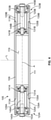
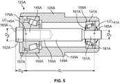
- FIG. 4-6 Another embodiment of a conveyor pulley 105 is shown in Figures 4-6 .
- the components shown in Figures 4-6 that are analogous to those of Figures 1-3 are designated by the corresponding reference number of Figures 1-3 plus "100" (e.g., part 41 becomes 141).
- the conveyor pulley 105 includes a first stub shaft assembly 123A and a second stub shaft assembly 123B.
- Each stub shaft assembly 123A, 123B includes an inboard bearing 141A, 141B and an outboard bearing 145A, 145B (which may be referred to as “inner” and “outer” bearings).
- the outboard bearings 145A, 145B and the inboard bearings 141A, 141B are tapered roller bearings.
- the stub shaft assembly 123A includes a push nut 185A to secure the stub shaft assembly housing 125A to the stub-shaft 149A.
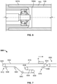
- FIG. 7 shows an example belt conveyor system 600 for moving articles A in which embodiments of the conveyor pulley 5, 105 may be used.
- the conveyor belt system 600 includes a tail section 612 at which articles are loaded on the conveyor belt 610 and a head section 616 in which articles are discharged from the conveyor belt 610.
- the tail section 612 includes a tail pulley 620 around which a conveyor belt 610 is looped.
- the head section 616 includes a head pulley 624 around which the conveyor belt 610 is looped.
- the conveyor belt 610 supports the articles A and rotates around the tail pulley 620 and head pulley 624.
- the articles A are supported on an outer surface 632 of the conveyor belt 610.
- An inner surface 634 of the conveyor belt 610 contacts the tail pulley 620 and the head pulley 624.
- the conveyor pulley 5, 105 ( Figs. 1-6 ) of embodiments of the present disclosure described above is the tail pulley 620 or the head pulley 624 of the belt conveyor system 600. In some embodiments, the conveyor pulley 5, 105 of embodiments of the present disclosure described above is both the tail pulley 620 and the head pulley 624.
- the system 600 includes a drive pulley 630 to cause rotation of the conveyor belt 610.
- the drive pulley may be the head pulley 624 of the system (e.g., such as in processing of bulk material) and the tail pulley 620 is an embodiment of the pulley 5, 105 ( Figs. 1-6 ) described above.
- the system 600 includes snub pulleys 636 to increase the contact angle of the belt 610 near the tail and head pulleys 620, 624.
- the system 600 includes a take-up pulley 638 to maintain tension on the belt 610 and bend pulleys 640 to change the direction of the belt 610.
- the system 600 may also include idler rollers (not shown) between the head pulley 624 and tail pulley 620 for supporting the weight of the belt 610 and articles.
- the conveyor pulley 5, 105 of embodiments the present disclosure is not an idler roller (i.e., the pulley causes the belt to change direction).
- the system of Figure 7 is an example and other arrangements of pulleys (e.g., rearrangement, addition or elimination of drive, snub, bend and/or take-up pulleys) may be used without limitation unless stated otherwise.
- the system 600 also includes an upstream conveyor (not shown) or downstream conveyor 650, such as a conveyor that is adapted to receive articles directly from the conveyor belt 610. It should also be understood that the conveyor system 600 is shown for illustration and is not drawn to scale.
- the conveyor system 600 may transport any article A such as articles processed in unit handling operations including, for example, packages that are shipped (e.g., items containing a barcode).
- the articles are bulk items (e.g., food, grain, mining materials or the like).
- the conveyor system 600 of Figure 7 described above may be used in various methods for transporting articles.
- articles are loaded onto the outer surface 632 of the conveyor belt 610 at the tail section 612.
- the tail pulley 620 and head pulley 624 are caused to rotate (e.g., by drive pulley 630) to rotate the conveyor belt and to cause articles to travel from the tail section 612 to the head section 616 of the belt conveyor system 600.
- Articles are discharged from the conveyor belt 610 at the head section 616 (e.g., onto a downstream conveyor 650).
- the conveyor pulleys of embodiments of the present disclosure have several advantages.
- a larger outboard bearing e.g., having an outer raceway diameter greater than the diameter of the center tube
- Such relatively small diameter pulleys are useful in unit handling applications as they reduce the gap between the pulleys to facilitate transfer of articles from one conveyor to the next conveyor.
- the articles maintain their orientation on the various conveyor belts during transfer between belts (e.g., to allow identifying information such as barcodes to maintain their orientation to allow the information to be read).
- the inboard bearing may be within the center tube which keeps attachment of the tube to the housing as close to the end of the pulley which reduces the bending moment load.
- shaft deflection is reduced which allows higher rated, more readily available (e.g., reduced cost) bearings, such as tapered bearings, to be used to increase the lifetime of the pulley.
- the ratio between the distance between the respective effective load centers of the inboard bearing and outboard bearing (D i ) and the distance between the end of the stub shaft and the effective load center of the outboard bearing (D o ) is at least about 1.5:1 or even at least about 2:1 or at least about 3:1 (e.g., about 4:1)
- the load on the outboard bearing is reduced which allows a smaller outboard bearing to be used.
- the ratio between the respective distances (D i /D o ) is less than about 7.5:1, less than about 6:1 or even less than about 5:1 (e.g., about 4:1) the amount of shaft deflection is reduced which allows higher rated bearings such as tapered bearings to be used.
- the stub shaft assemblies may more securely fit within the center tube.
- variability in tolerances is reduced (e.g., relative to clamping rings) which helps set the proper clearance for the bearings.
- the terms “about,” “substantially,” “essentially” and “approximately” when used in conjunction with ranges of dimensions, concentrations, temperatures or other physical or chemical properties or characteristics is meant to cover variations that may exist in the upper and/or lower limits of the ranges of the properties or characteristics, including, for example, variations resulting from rounding, measurement methodology or other statistical variation.
Landscapes
- Engineering & Computer Science (AREA)
- General Engineering & Computer Science (AREA)
- Mechanical Engineering (AREA)
- Pulleys (AREA)
- Rollers For Roller Conveyors For Transfer (AREA)
Claims (14)
- Poulie de convoyeur comprenant :un tube central (9) ayant une première extrémité et une seconde extrémité ;un premier ensemble d'arbre tronqué (23A), le premier ensemble d'arbre tronqué étant connecté au tube central au niveau de sa première extrémité ; etun second ensemble d'arbre tronqué (23B), le second ensemble d'arbre tronqué étant connecté au tube central au niveau de sa seconde extrémité, les premier et second ensembles d'arbre tronqué comprenant chacun : un palier intérieur (41A, 41B), le palier intérieur étant un palier à contact angulaire et ayant un diamètre d'alésage (D1) ;un palier extérieur (45A, 45B), le palier extérieur étant un palier à contact angulaire et ayant un diamètre d'alésage (D2) différent du diamètre d'alésage de palier intérieur ; etun arbre tronqué (49A, 49B) reçu dans le palier intérieur et le palier extérieur,caractérisée en ce que les premier et second ensembles d'arbre tronqué comprennent chacun en outre :
un boîtier d'ensemble d'arbre tronqué (25A, 25B), le boîtier comprenant :une partie de corps principal (29A, 29B) ; etune partie de tige (31A, 31B) qui s'étend depuis la partie de corps principal qui est reçue dans le tube central. - Poulie de convoyeur selon la revendication 1, dans laquelle le diamètre d'alésage de palier extérieur est supérieur au diamètre d'alésage de palier intérieur.
- Poulie de convoyeur selon la revendication 1, dans laquelle le palier intérieur est à l'intérieur du tube central et le palier extérieur est à extérieur au tube central.
- Poulie de convoyeur selon la revendication 3, dans laquelle le palier extérieur comprend un chemin de roulement extérieur ayant un diamètre extérieur et le tube central a un diamètre intérieur, le diamètre extérieur du chemin de roulement extérieur étant supérieur au diamètre intérieur du tube central.
- Poulie de convoyeur selon la revendication 1, dans laquelle la partie de corps principal de l'ensemble d'arbre tronqué a un diamètre extérieur, le diamètre extérieur étant le même que le diamètre du tube central.
- Poulie de convoyeur selon la revendication 1, dans laquelle chaque arbre tronqué comprend une partie de corps principal (50A,B) et une partie de diamètre réduit (51A,B) qui s'étend depuis le corps principal, la partie de corps principal étant reçue dans le palier extérieur et la partie de diamètre réduit étant reçue dans le palier intérieur.
- Poulie de convoyeur selon la revendication 1, dans laquelle chacun des palier intérieur et palier extérieur est choisi parmi le groupe constitué d'un palier à rouleaux, palier à billes, palier cylindrique, palier à aiguilles, et palier sphérique.
- Poulie de convoyeur selon la revendication 1, dans laquelle le palier extérieur comprend un chemin de roulement intérieur (57A), le chemin de roulement intérieur étant en contact avec l'arbre tronqué.
- Poulie de convoyeur selon la revendication 1, dans laquelle le palier extérieur est un palier à rouleaux coniques.
- Poulie de convoyeur selon la revendication 1, dans laquelle la poulie de convoyeur n'est pas soumise à une rotation motorisée et le tube central a un diamètre inférieur à 10,16 centimètres (4 pouces).
- Poulie de convoyeur selon la revendication 1, dans laquelle le palier extérieur a une charge nominale supérieure à une charge nominale du palier intérieur.
- Système de convoyeur à bande pour déplacer des articles, le système de convoyeur comprenant :une bande transporteuse (610);une section de queue (612) au niveau de laquelle des articles sont chargés sur la bande transporteuse, la section de queue comprenant une poulie de queue (620) autour de laquelle la bande transporteuse est enroulée ; etune section de tête (616) au niveau de laquelle des articles sont déchargés de la bande transporteuse, la section de tête comprenant une poulie de tête (624) autour de laquelle la bande transporteuse est enroulée, la poulie de convoyeur selon la revendication 1 étant la poulie de queue ou la poulie de tête.
- Poulie de convoyeur comprenant :un tube central (9) ayant une première extrémité et une seconde extrémité ;un premier ensemble d'arbre tronqué (23A), le premier ensemble d'arbre tronqué étant partiellement reçu dans le tube central au niveau de sa première extrémité ;un second ensemble d'arbre tronqué (23B), le second ensemble d'arbre tronqué étant partiellement reçu dans le tube central au niveau de sa seconde extrémité, les premier et second ensembles d'arbre tronqué comprenant chacun :un palier interne (41A, 41B) à l'intérieur du tube central ;un palier externe (45A, 45B) ; etun arbre tronqué (49A, 49B) reçu dans l'ensemble de palier interne et le palier externe,caractérisée en ce que le palier externe est extérieur au tube central.
- Poulie de convoyeur comprenant :un tube central (9) ayant une première extrémité et une seconde extrémité ;un premier ensemble d'arbre tronqué (23A), le premier ensemble d'arbre tronqué étant connecté au tube central au niveau de sa première extrémité ; etun second ensemble d'arbre tronqué (23B), le second ensemble d'arbre tronqué étant connecté au tube central au niveau de sa seconde extrémité, les premier et second ensembles d'arbre tronqué ayant chacun une extrémité extérieure et comprenant chacun :un palier extérieur (45A, 45B) ayant un centre de charge effectif, une distance Do existant entre l'extrémité extérieure de l'ensemble d'arbre tronqué et le centre de charge effectif de palier extérieur,un palier intérieur (41A, 41B) ayant un centre de charge effectif, une distance Di existant entre le centre de charge effectif de palier extérieur et le centre de charge effectif de palier intérieur,caractérisée en ce que le rapport entre Di et Do est d'au moins environ 1,5:1.
Applications Claiming Priority (2)
| Application Number | Priority Date | Filing Date | Title |
|---|---|---|---|
| US15/597,945 US10017328B1 (en) | 2017-05-17 | 2017-05-17 | Stub shaft conveyor pulleys |
| PCT/US2018/029093 WO2018212944A1 (fr) | 2017-05-17 | 2018-04-24 | Poulies de transporteur d'arbre de liaison |
Publications (3)
| Publication Number | Publication Date |
|---|---|
| EP3625155A1 EP3625155A1 (fr) | 2020-03-25 |
| EP3625155A4 EP3625155A4 (fr) | 2021-02-24 |
| EP3625155B1 true EP3625155B1 (fr) | 2022-02-23 |
Family
ID=62750372
Family Applications (1)
| Application Number | Title | Priority Date | Filing Date |
|---|---|---|---|
| EP18802574.6A Not-in-force EP3625155B1 (fr) | 2017-05-17 | 2018-04-24 | Poulies de transporteur d'arbre de liaison |
Country Status (5)
| Country | Link |
|---|---|
| US (1) | US10017328B1 (fr) |
| EP (1) | EP3625155B1 (fr) |
| CA (1) | CA3061507C (fr) |
| MX (1) | MX2019012378A (fr) |
| WO (1) | WO2018212944A1 (fr) |
Families Citing this family (3)
| Publication number | Priority date | Publication date | Assignee | Title |
|---|---|---|---|---|
| US11071250B2 (en) * | 2018-02-08 | 2021-07-27 | Firefly Automatix, Inc. | Mower deck roller assembly |
| US11130639B2 (en) | 2019-12-20 | 2021-09-28 | Abb Schweiz Ag | Modular pulley for continuous belt conveyor system |
| US12195281B1 (en) | 2023-01-06 | 2025-01-14 | Josh Cox | Tail pulley and belt saver |
Family Cites Families (15)
| Publication number | Priority date | Publication date | Assignee | Title |
|---|---|---|---|---|
| US3762272A (en) * | 1968-05-23 | 1973-10-02 | Fresco Ind Inc | Self-adjusting extensible gear train and assemblies containing same |
| DE2205242A1 (de) | 1972-02-04 | 1973-08-09 | Stein Ohg Hans | Rolle |
| EP0015740B1 (fr) | 1979-03-09 | 1983-04-27 | Skf (U.K.) Limited | Aménagement de capuchons d'extrémité pour rouleaux transporteurs |
| US5022132A (en) | 1989-12-26 | 1991-06-11 | Precision Pulley, Inc. | Apparatus for rotatably mounting idlers and pulleys of various sizes |
| US5865290A (en) | 1998-05-15 | 1999-02-02 | Scott; Charles Winfield | Conveyor roller insert |
| US6516942B2 (en) * | 2001-03-20 | 2003-02-11 | Fmc Technologies, Inc. | Idler roller for transport conveyor |
| US7028825B2 (en) | 2004-04-02 | 2006-04-18 | Scott C Winfield | Conveyor roller assembly, conveyor roller insert and axle for conveyor roller |
| US20060180426A1 (en) | 2005-01-31 | 2006-08-17 | Scott C W | Conveyor roller assembly |
| US20070181400A1 (en) * | 2006-02-06 | 2007-08-09 | Globe Composites Solutions, Ltd | Roller assembly and method of making |
| US20070261933A1 (en) | 2006-04-26 | 2007-11-15 | Scott C W | Conveyor roller assembly and conveyor roller insert |
| EP2161223B2 (fr) | 2008-09-07 | 2023-02-22 | Itoh Denki Co., Ltd. | Rouleau motorisé et unité de moteur pour rouleau motorisé |
| KR101132374B1 (ko) | 2010-04-01 | 2012-04-03 | 김원진 | 벨트 컨베이어용 롤러 |
| US8727105B2 (en) | 2011-05-13 | 2014-05-20 | Sst Bearing Corporation | Roller inserts for conveyor rollers and roller assemblies including the same |
| US9676553B2 (en) * | 2013-09-06 | 2017-06-13 | Matthew Earl Wallace | Conveyor roller with integral clutch |
| JP6315554B2 (ja) * | 2014-02-13 | 2018-04-25 | 三機工業株式会社 | ベルトコンベヤ装置用の駆動装置 |
-
2017
- 2017-05-17 US US15/597,945 patent/US10017328B1/en active Active
-
2018
- 2018-04-24 WO PCT/US2018/029093 patent/WO2018212944A1/fr not_active Ceased
- 2018-04-24 EP EP18802574.6A patent/EP3625155B1/fr not_active Not-in-force
- 2018-04-24 CA CA3061507A patent/CA3061507C/fr active Active
- 2018-04-24 MX MX2019012378A patent/MX2019012378A/es unknown
Also Published As
| Publication number | Publication date |
|---|---|
| WO2018212944A1 (fr) | 2018-11-22 |
| CA3061507A1 (fr) | 2018-11-22 |
| EP3625155A4 (fr) | 2021-02-24 |
| CA3061507C (fr) | 2022-08-23 |
| US10017328B1 (en) | 2018-07-10 |
| EP3625155A1 (fr) | 2020-03-25 |
| MX2019012378A (es) | 2020-01-20 |
Similar Documents
| Publication | Publication Date | Title |
|---|---|---|
| EP3625155B1 (fr) | Poulies de transporteur d'arbre de liaison | |
| US6516942B2 (en) | Idler roller for transport conveyor | |
| US8430801B2 (en) | Lightweight conveyor roller | |
| AU2002252178A1 (en) | Idler roller for transport conveyor | |
| US8739965B2 (en) | Wing pulley having central reinforcing disk | |
| EP1663819A1 (fr) | Chaine transporteuse articulee modulaire equipee d'ensembles rotatifs destines a venir en contact avec des articles | |
| US6390289B1 (en) | Conveyor belt alignment device | |
| FI109895B (fi) | Kuljetinlaitteisto | |
| US20040050670A1 (en) | Bushing system for live roller conveyor | |
| US20170096303A1 (en) | Conveyor belt idler systems | |
| US4353459A (en) | Conveyor chain | |
| US10472179B2 (en) | Cartridge bearing assembly for roller conveyors | |
| US20150166264A1 (en) | Conveyor belt aligning apparatus | |
| US2555765A (en) | Troughing idler | |
| KR101367299B1 (ko) | 사행 방지 장치 및 이를 이용한 사행 방지 방법 | |
| KR102381407B1 (ko) | 물류용 소터 | |
| AU2019392292B2 (en) | Catenary troughing idler | |
| JPH0616324U (ja) | コンベア搬送装置 | |
| JPH1072110A (ja) | ローラコンベア | |
| US20220281692A1 (en) | Roller Assembly For Singulator | |
| JP2001199517A (ja) | 搬送装置 | |
| US20030045413A1 (en) | Roller assembly with bushing | |
| US20160272433A1 (en) | Drum motors having a polymer body shell | |
| JP2020189712A (ja) | ローラチェーンの組み立てに用いられるローラユニット | |
| JP2007254041A (ja) | 仕分け設備 |
Legal Events
| Date | Code | Title | Description |
|---|---|---|---|
| STAA | Information on the status of an ep patent application or granted ep patent |
Free format text: STATUS: THE INTERNATIONAL PUBLICATION HAS BEEN MADE |
|
| PUAI | Public reference made under article 153(3) epc to a published international application that has entered the european phase |
Free format text: ORIGINAL CODE: 0009012 |
|
| STAA | Information on the status of an ep patent application or granted ep patent |
Free format text: STATUS: REQUEST FOR EXAMINATION WAS MADE |
|
| 17P | Request for examination filed |
Effective date: 20191111 |
|
| AK | Designated contracting states |
Kind code of ref document: A1 Designated state(s): AL AT BE BG CH CY CZ DE DK EE ES FI FR GB GR HR HU IE IS IT LI LT LU LV MC MK MT NL NO PL PT RO RS SE SI SK SM TR |
|
| AX | Request for extension of the european patent |
Extension state: BA ME |
|
| DAV | Request for validation of the european patent (deleted) | ||
| DAX | Request for extension of the european patent (deleted) | ||
| A4 | Supplementary search report drawn up and despatched |
Effective date: 20210125 |
|
| RIC1 | Information provided on ipc code assigned before grant |
Ipc: F16C 19/56 20060101ALI20210119BHEP Ipc: B65G 23/04 20060101AFI20210119BHEP |
|
| GRAP | Despatch of communication of intention to grant a patent |
Free format text: ORIGINAL CODE: EPIDOSNIGR1 |
|
| STAA | Information on the status of an ep patent application or granted ep patent |
Free format text: STATUS: GRANT OF PATENT IS INTENDED |
|
| RIC1 | Information provided on ipc code assigned before grant |
Ipc: F16C 19/56 20060101ALI20211008BHEP Ipc: B65G 23/04 20060101AFI20211008BHEP |
|
| INTG | Intention to grant announced |
Effective date: 20211027 |
|
| GRAS | Grant fee paid |
Free format text: ORIGINAL CODE: EPIDOSNIGR3 |
|
| GRAA | (expected) grant |
Free format text: ORIGINAL CODE: 0009210 |
|
| STAA | Information on the status of an ep patent application or granted ep patent |
Free format text: STATUS: THE PATENT HAS BEEN GRANTED |
|
| AK | Designated contracting states |
Kind code of ref document: B1 Designated state(s): AL AT BE BG CH CY CZ DE DK EE ES FI FR GB GR HR HU IE IS IT LI LT LU LV MC MK MT NL NO PL PT RO RS SE SI SK SM TR |
|
| REG | Reference to a national code |
Ref country code: GB Ref legal event code: FG4D |
|
| REG | Reference to a national code |
Ref country code: CH Ref legal event code: EP |
|
| REG | Reference to a national code |
Ref country code: DE Ref legal event code: R096 Ref document number: 602018031325 Country of ref document: DE |
|
| REG | Reference to a national code |
Ref country code: AT Ref legal event code: REF Ref document number: 1470306 Country of ref document: AT Kind code of ref document: T Effective date: 20220315 |
|
| REG | Reference to a national code |
Ref country code: IE Ref legal event code: FG4D |
|
| REG | Reference to a national code |
Ref country code: LT Ref legal event code: MG9D |
|
| REG | Reference to a national code |
Ref country code: NL Ref legal event code: MP Effective date: 20220223 |
|
| REG | Reference to a national code |
Ref country code: AT Ref legal event code: MK05 Ref document number: 1470306 Country of ref document: AT Kind code of ref document: T Effective date: 20220223 |
|
| PG25 | Lapsed in a contracting state [announced via postgrant information from national office to epo] |
Ref country code: SE Free format text: LAPSE BECAUSE OF FAILURE TO SUBMIT A TRANSLATION OF THE DESCRIPTION OR TO PAY THE FEE WITHIN THE PRESCRIBED TIME-LIMIT Effective date: 20220223 Ref country code: RS Free format text: LAPSE BECAUSE OF FAILURE TO SUBMIT A TRANSLATION OF THE DESCRIPTION OR TO PAY THE FEE WITHIN THE PRESCRIBED TIME-LIMIT Effective date: 20220223 Ref country code: PT Free format text: LAPSE BECAUSE OF FAILURE TO SUBMIT A TRANSLATION OF THE DESCRIPTION OR TO PAY THE FEE WITHIN THE PRESCRIBED TIME-LIMIT Effective date: 20220623 Ref country code: NO Free format text: LAPSE BECAUSE OF FAILURE TO SUBMIT A TRANSLATION OF THE DESCRIPTION OR TO PAY THE FEE WITHIN THE PRESCRIBED TIME-LIMIT Effective date: 20220523 Ref country code: NL Free format text: LAPSE BECAUSE OF FAILURE TO SUBMIT A TRANSLATION OF THE DESCRIPTION OR TO PAY THE FEE WITHIN THE PRESCRIBED TIME-LIMIT Effective date: 20220223 Ref country code: LT Free format text: LAPSE BECAUSE OF FAILURE TO SUBMIT A TRANSLATION OF THE DESCRIPTION OR TO PAY THE FEE WITHIN THE PRESCRIBED TIME-LIMIT Effective date: 20220223 Ref country code: HR Free format text: LAPSE BECAUSE OF FAILURE TO SUBMIT A TRANSLATION OF THE DESCRIPTION OR TO PAY THE FEE WITHIN THE PRESCRIBED TIME-LIMIT Effective date: 20220223 Ref country code: ES Free format text: LAPSE BECAUSE OF FAILURE TO SUBMIT A TRANSLATION OF THE DESCRIPTION OR TO PAY THE FEE WITHIN THE PRESCRIBED TIME-LIMIT Effective date: 20220223 Ref country code: BG Free format text: LAPSE BECAUSE OF FAILURE TO SUBMIT A TRANSLATION OF THE DESCRIPTION OR TO PAY THE FEE WITHIN THE PRESCRIBED TIME-LIMIT Effective date: 20220523 |
|
| PG25 | Lapsed in a contracting state [announced via postgrant information from national office to epo] |
Ref country code: PL Free format text: LAPSE BECAUSE OF FAILURE TO SUBMIT A TRANSLATION OF THE DESCRIPTION OR TO PAY THE FEE WITHIN THE PRESCRIBED TIME-LIMIT Effective date: 20220223 Ref country code: LV Free format text: LAPSE BECAUSE OF FAILURE TO SUBMIT A TRANSLATION OF THE DESCRIPTION OR TO PAY THE FEE WITHIN THE PRESCRIBED TIME-LIMIT Effective date: 20220223 Ref country code: GR Free format text: LAPSE BECAUSE OF FAILURE TO SUBMIT A TRANSLATION OF THE DESCRIPTION OR TO PAY THE FEE WITHIN THE PRESCRIBED TIME-LIMIT Effective date: 20220524 Ref country code: FI Free format text: LAPSE BECAUSE OF FAILURE TO SUBMIT A TRANSLATION OF THE DESCRIPTION OR TO PAY THE FEE WITHIN THE PRESCRIBED TIME-LIMIT Effective date: 20220223 Ref country code: AT Free format text: LAPSE BECAUSE OF FAILURE TO SUBMIT A TRANSLATION OF THE DESCRIPTION OR TO PAY THE FEE WITHIN THE PRESCRIBED TIME-LIMIT Effective date: 20220223 |
|
| PG25 | Lapsed in a contracting state [announced via postgrant information from national office to epo] |
Ref country code: IS Free format text: LAPSE BECAUSE OF FAILURE TO SUBMIT A TRANSLATION OF THE DESCRIPTION OR TO PAY THE FEE WITHIN THE PRESCRIBED TIME-LIMIT Effective date: 20220623 |
|
| PG25 | Lapsed in a contracting state [announced via postgrant information from national office to epo] |
Ref country code: SM Free format text: LAPSE BECAUSE OF FAILURE TO SUBMIT A TRANSLATION OF THE DESCRIPTION OR TO PAY THE FEE WITHIN THE PRESCRIBED TIME-LIMIT Effective date: 20220223 Ref country code: SK Free format text: LAPSE BECAUSE OF FAILURE TO SUBMIT A TRANSLATION OF THE DESCRIPTION OR TO PAY THE FEE WITHIN THE PRESCRIBED TIME-LIMIT Effective date: 20220223 Ref country code: RO Free format text: LAPSE BECAUSE OF FAILURE TO SUBMIT A TRANSLATION OF THE DESCRIPTION OR TO PAY THE FEE WITHIN THE PRESCRIBED TIME-LIMIT Effective date: 20220223 Ref country code: EE Free format text: LAPSE BECAUSE OF FAILURE TO SUBMIT A TRANSLATION OF THE DESCRIPTION OR TO PAY THE FEE WITHIN THE PRESCRIBED TIME-LIMIT Effective date: 20220223 Ref country code: DK Free format text: LAPSE BECAUSE OF FAILURE TO SUBMIT A TRANSLATION OF THE DESCRIPTION OR TO PAY THE FEE WITHIN THE PRESCRIBED TIME-LIMIT Effective date: 20220223 Ref country code: CZ Free format text: LAPSE BECAUSE OF FAILURE TO SUBMIT A TRANSLATION OF THE DESCRIPTION OR TO PAY THE FEE WITHIN THE PRESCRIBED TIME-LIMIT Effective date: 20220223 |
|
| REG | Reference to a national code |
Ref country code: DE Ref legal event code: R097 Ref document number: 602018031325 Country of ref document: DE |
|
| PG25 | Lapsed in a contracting state [announced via postgrant information from national office to epo] |
Ref country code: AL Free format text: LAPSE BECAUSE OF FAILURE TO SUBMIT A TRANSLATION OF THE DESCRIPTION OR TO PAY THE FEE WITHIN THE PRESCRIBED TIME-LIMIT Effective date: 20220223 |
|
| REG | Reference to a national code |
Ref country code: CH Ref legal event code: PL |
|
| PLBE | No opposition filed within time limit |
Free format text: ORIGINAL CODE: 0009261 |
|
| STAA | Information on the status of an ep patent application or granted ep patent |
Free format text: STATUS: NO OPPOSITION FILED WITHIN TIME LIMIT |
|
| REG | Reference to a national code |
Ref country code: BE Ref legal event code: MM Effective date: 20220430 |
|
| PG25 | Lapsed in a contracting state [announced via postgrant information from national office to epo] |
Ref country code: MC Free format text: LAPSE BECAUSE OF FAILURE TO SUBMIT A TRANSLATION OF THE DESCRIPTION OR TO PAY THE FEE WITHIN THE PRESCRIBED TIME-LIMIT Effective date: 20220223 Ref country code: LU Free format text: LAPSE BECAUSE OF NON-PAYMENT OF DUE FEES Effective date: 20220424 Ref country code: LI Free format text: LAPSE BECAUSE OF NON-PAYMENT OF DUE FEES Effective date: 20220430 Ref country code: CH Free format text: LAPSE BECAUSE OF NON-PAYMENT OF DUE FEES Effective date: 20220430 |
|
| 26N | No opposition filed |
Effective date: 20221124 |
|
| PG25 | Lapsed in a contracting state [announced via postgrant information from national office to epo] |
Ref country code: SI Free format text: LAPSE BECAUSE OF FAILURE TO SUBMIT A TRANSLATION OF THE DESCRIPTION OR TO PAY THE FEE WITHIN THE PRESCRIBED TIME-LIMIT Effective date: 20220223 Ref country code: BE Free format text: LAPSE BECAUSE OF NON-PAYMENT OF DUE FEES Effective date: 20220430 |
|
| PG25 | Lapsed in a contracting state [announced via postgrant information from national office to epo] |
Ref country code: IE Free format text: LAPSE BECAUSE OF NON-PAYMENT OF DUE FEES Effective date: 20220424 |
|
| PG25 | Lapsed in a contracting state [announced via postgrant information from national office to epo] |
Ref country code: IT Free format text: LAPSE BECAUSE OF FAILURE TO SUBMIT A TRANSLATION OF THE DESCRIPTION OR TO PAY THE FEE WITHIN THE PRESCRIBED TIME-LIMIT Effective date: 20220223 |
|
| PG25 | Lapsed in a contracting state [announced via postgrant information from national office to epo] |
Ref country code: MK Free format text: LAPSE BECAUSE OF FAILURE TO SUBMIT A TRANSLATION OF THE DESCRIPTION OR TO PAY THE FEE WITHIN THE PRESCRIBED TIME-LIMIT Effective date: 20220223 Ref country code: CY Free format text: LAPSE BECAUSE OF FAILURE TO SUBMIT A TRANSLATION OF THE DESCRIPTION OR TO PAY THE FEE WITHIN THE PRESCRIBED TIME-LIMIT Effective date: 20220223 |
|
| PG25 | Lapsed in a contracting state [announced via postgrant information from national office to epo] |
Ref country code: HU Free format text: LAPSE BECAUSE OF FAILURE TO SUBMIT A TRANSLATION OF THE DESCRIPTION OR TO PAY THE FEE WITHIN THE PRESCRIBED TIME-LIMIT; INVALID AB INITIO Effective date: 20180424 |
|
| PG25 | Lapsed in a contracting state [announced via postgrant information from national office to epo] |
Ref country code: TR Free format text: LAPSE BECAUSE OF FAILURE TO SUBMIT A TRANSLATION OF THE DESCRIPTION OR TO PAY THE FEE WITHIN THE PRESCRIBED TIME-LIMIT Effective date: 20220223 |
|
| PGFP | Annual fee paid to national office [announced via postgrant information from national office to epo] |
Ref country code: GB Payment date: 20240429 Year of fee payment: 7 |
|
| PGFP | Annual fee paid to national office [announced via postgrant information from national office to epo] |
Ref country code: DE Payment date: 20240429 Year of fee payment: 7 |
|
| PGFP | Annual fee paid to national office [announced via postgrant information from national office to epo] |
Ref country code: FR Payment date: 20240425 Year of fee payment: 7 |
|
| PG25 | Lapsed in a contracting state [announced via postgrant information from national office to epo] |
Ref country code: MT Free format text: LAPSE BECAUSE OF FAILURE TO SUBMIT A TRANSLATION OF THE DESCRIPTION OR TO PAY THE FEE WITHIN THE PRESCRIBED TIME-LIMIT Effective date: 20220223 |
|
| REG | Reference to a national code |
Ref country code: DE Ref legal event code: R119 Ref document number: 602018031325 Country of ref document: DE |
|
| GBPC | Gb: european patent ceased through non-payment of renewal fee |
Effective date: 20250424 |
|
| PG25 | Lapsed in a contracting state [announced via postgrant information from national office to epo] |
Ref country code: DE Free format text: LAPSE BECAUSE OF NON-PAYMENT OF DUE FEES Effective date: 20251104 |
|
| PG25 | Lapsed in a contracting state [announced via postgrant information from national office to epo] |
Ref country code: GB Free format text: LAPSE BECAUSE OF NON-PAYMENT OF DUE FEES Effective date: 20250424 |
|
| PG25 | Lapsed in a contracting state [announced via postgrant information from national office to epo] |
Ref country code: FR Free format text: LAPSE BECAUSE OF NON-PAYMENT OF DUE FEES Effective date: 20250430 |