EP3625193B1 - Thermisches material mit hoher kapazität und hoher leitfähigkeit, verfahren zu dessen herstellung und von komponenten damit - Google Patents
Thermisches material mit hoher kapazität und hoher leitfähigkeit, verfahren zu dessen herstellung und von komponenten damit Download PDFInfo
- Publication number
- EP3625193B1 EP3625193B1 EP18723544.5A EP18723544A EP3625193B1 EP 3625193 B1 EP3625193 B1 EP 3625193B1 EP 18723544 A EP18723544 A EP 18723544A EP 3625193 B1 EP3625193 B1 EP 3625193B1
- Authority
- EP
- European Patent Office
- Prior art keywords
- pcm
- mcp
- continuous
- surface portion
- composite material
- Prior art date
- Legal status (The legal status is an assumption and is not a legal conclusion. Google has not performed a legal analysis and makes no representation as to the accuracy of the status listed.)
- Active
Links
Images

Classifications
-
- C—CHEMISTRY; METALLURGY
- C04—CEMENTS; CONCRETE; ARTIFICIAL STONE; CERAMICS; REFRACTORIES
- C04B—LIME, MAGNESIA; SLAG; CEMENTS; COMPOSITIONS THEREOF, e.g. MORTARS, CONCRETE OR LIKE BUILDING MATERIALS; ARTIFICIAL STONE; CERAMICS; REFRACTORIES; TREATMENT OF NATURAL STONE
- C04B35/00—Shaped ceramic products characterised by their composition; Ceramics compositions; Processing powders of inorganic compounds preparatory to the manufacturing of ceramic products
- C04B35/515—Shaped ceramic products characterised by their composition; Ceramics compositions; Processing powders of inorganic compounds preparatory to the manufacturing of ceramic products based on non-oxide ceramics
- C04B35/58—Shaped ceramic products characterised by their composition; Ceramics compositions; Processing powders of inorganic compounds preparatory to the manufacturing of ceramic products based on non-oxide ceramics based on borides, nitrides, i.e. nitrides, oxynitrides, carbonitrides or oxycarbonitrides or silicides
- C04B35/583—Shaped ceramic products characterised by their composition; Ceramics compositions; Processing powders of inorganic compounds preparatory to the manufacturing of ceramic products based on non-oxide ceramics based on borides, nitrides, i.e. nitrides, oxynitrides, carbonitrides or oxycarbonitrides or silicides based on boron nitride
-
- C—CHEMISTRY; METALLURGY
- C04—CEMENTS; CONCRETE; ARTIFICIAL STONE; CERAMICS; REFRACTORIES
- C04B—LIME, MAGNESIA; SLAG; CEMENTS; COMPOSITIONS THEREOF, e.g. MORTARS, CONCRETE OR LIKE BUILDING MATERIALS; ARTIFICIAL STONE; CERAMICS; REFRACTORIES; TREATMENT OF NATURAL STONE
- C04B35/00—Shaped ceramic products characterised by their composition; Ceramics compositions; Processing powders of inorganic compounds preparatory to the manufacturing of ceramic products
- C04B35/622—Forming processes; Processing powders of inorganic compounds preparatory to the manufacturing of ceramic products
- C04B35/626—Preparing or treating the powders individually or as batches ; preparing or treating macroscopic reinforcing agents for ceramic products, e.g. fibres; mechanical aspects section B
- C04B35/63—Preparing or treating the powders individually or as batches ; preparing or treating macroscopic reinforcing agents for ceramic products, e.g. fibres; mechanical aspects section B using additives specially adapted for forming the products, e.g.. binder binders
- C04B35/632—Organic additives
-
- C—CHEMISTRY; METALLURGY
- C04—CEMENTS; CONCRETE; ARTIFICIAL STONE; CERAMICS; REFRACTORIES
- C04B—LIME, MAGNESIA; SLAG; CEMENTS; COMPOSITIONS THEREOF, e.g. MORTARS, CONCRETE OR LIKE BUILDING MATERIALS; ARTIFICIAL STONE; CERAMICS; REFRACTORIES; TREATMENT OF NATURAL STONE
- C04B38/00—Porous mortars, concrete, artificial stone or ceramic ware; Preparation thereof
- C04B38/04—Porous mortars, concrete, artificial stone or ceramic ware; Preparation thereof by dissolving-out added substances
- C04B38/045—Porous mortars, concrete, artificial stone or ceramic ware; Preparation thereof by dissolving-out added substances the dissolved-out substance being a monolitic element having approximately the same dimensions as the final article, e.g. a prepreg obtained by bonding together dissolvable particles
-
- C—CHEMISTRY; METALLURGY
- C04—CEMENTS; CONCRETE; ARTIFICIAL STONE; CERAMICS; REFRACTORIES
- C04B—LIME, MAGNESIA; SLAG; CEMENTS; COMPOSITIONS THEREOF, e.g. MORTARS, CONCRETE OR LIKE BUILDING MATERIALS; ARTIFICIAL STONE; CERAMICS; REFRACTORIES; TREATMENT OF NATURAL STONE
- C04B41/00—After-treatment of mortars, concrete, artificial stone or ceramics; Treatment of natural stone
- C04B41/009—After-treatment of mortars, concrete, artificial stone or ceramics; Treatment of natural stone characterised by the material treated
-
- C—CHEMISTRY; METALLURGY
- C04—CEMENTS; CONCRETE; ARTIFICIAL STONE; CERAMICS; REFRACTORIES
- C04B—LIME, MAGNESIA; SLAG; CEMENTS; COMPOSITIONS THEREOF, e.g. MORTARS, CONCRETE OR LIKE BUILDING MATERIALS; ARTIFICIAL STONE; CERAMICS; REFRACTORIES; TREATMENT OF NATURAL STONE
- C04B41/00—After-treatment of mortars, concrete, artificial stone or ceramics; Treatment of natural stone
- C04B41/45—Coating or impregnating, e.g. injection in masonry, partial coating of green or fired ceramics, organic coating compositions for adhering together two concrete elements
- C04B41/4572—Partial coating or impregnation of the surface of the substrate
-
- C—CHEMISTRY; METALLURGY
- C04—CEMENTS; CONCRETE; ARTIFICIAL STONE; CERAMICS; REFRACTORIES
- C04B—LIME, MAGNESIA; SLAG; CEMENTS; COMPOSITIONS THEREOF, e.g. MORTARS, CONCRETE OR LIKE BUILDING MATERIALS; ARTIFICIAL STONE; CERAMICS; REFRACTORIES; TREATMENT OF NATURAL STONE
- C04B41/00—After-treatment of mortars, concrete, artificial stone or ceramics; Treatment of natural stone
- C04B41/45—Coating or impregnating, e.g. injection in masonry, partial coating of green or fired ceramics, organic coating compositions for adhering together two concrete elements
- C04B41/46—Coating or impregnating, e.g. injection in masonry, partial coating of green or fired ceramics, organic coating compositions for adhering together two concrete elements with organic materials
- C04B41/47—Oils, fats or waxes natural resins
- C04B41/478—Bitumen, asphalt, e.g. paraffin
-
- C—CHEMISTRY; METALLURGY
- C04—CEMENTS; CONCRETE; ARTIFICIAL STONE; CERAMICS; REFRACTORIES
- C04B—LIME, MAGNESIA; SLAG; CEMENTS; COMPOSITIONS THEREOF, e.g. MORTARS, CONCRETE OR LIKE BUILDING MATERIALS; ARTIFICIAL STONE; CERAMICS; REFRACTORIES; TREATMENT OF NATURAL STONE
- C04B41/00—After-treatment of mortars, concrete, artificial stone or ceramics; Treatment of natural stone
- C04B41/80—After-treatment of mortars, concrete, artificial stone or ceramics; Treatment of natural stone of only ceramics
- C04B41/81—Coating or impregnation
- C04B41/82—Coating or impregnation with organic materials
-
- C—CHEMISTRY; METALLURGY
- C04—CEMENTS; CONCRETE; ARTIFICIAL STONE; CERAMICS; REFRACTORIES
- C04B—LIME, MAGNESIA; SLAG; CEMENTS; COMPOSITIONS THEREOF, e.g. MORTARS, CONCRETE OR LIKE BUILDING MATERIALS; ARTIFICIAL STONE; CERAMICS; REFRACTORIES; TREATMENT OF NATURAL STONE
- C04B2103/00—Function or property of ingredients for mortars, concrete or artificial stone
- C04B2103/0068—Ingredients with a function or property not provided for elsewhere in C04B2103/00
- C04B2103/0071—Phase-change materials, e.g. latent heat storage materials used in concrete compositions
-
- C—CHEMISTRY; METALLURGY
- C04—CEMENTS; CONCRETE; ARTIFICIAL STONE; CERAMICS; REFRACTORIES
- C04B—LIME, MAGNESIA; SLAG; CEMENTS; COMPOSITIONS THEREOF, e.g. MORTARS, CONCRETE OR LIKE BUILDING MATERIALS; ARTIFICIAL STONE; CERAMICS; REFRACTORIES; TREATMENT OF NATURAL STONE
- C04B2235/00—Aspects relating to ceramic starting mixtures or sintered ceramic products
- C04B2235/60—Aspects relating to the preparation, properties or mechanical treatment of green bodies or pre-forms
- C04B2235/616—Liquid infiltration of green bodies or pre-forms
-
- C—CHEMISTRY; METALLURGY
- C09—DYES; PAINTS; POLISHES; NATURAL RESINS; ADHESIVES; COMPOSITIONS NOT OTHERWISE PROVIDED FOR; APPLICATIONS OF MATERIALS NOT OTHERWISE PROVIDED FOR
- C09K—MATERIALS FOR MISCELLANEOUS APPLICATIONS, NOT PROVIDED FOR ELSEWHERE
- C09K5/00—Heat-transfer, heat-exchange or heat-storage materials, e.g. refrigerants; Materials for the production of heat or cold by chemical reactions other than by combustion
- C09K5/02—Materials undergoing a change of physical state when used
- C09K5/06—Materials undergoing a change of physical state when used the change of state being from liquid to solid or vice versa
- C09K5/063—Materials absorbing or liberating heat during crystallisation; Heat storage materials
-
- Y—GENERAL TAGGING OF NEW TECHNOLOGICAL DEVELOPMENTS; GENERAL TAGGING OF CROSS-SECTIONAL TECHNOLOGIES SPANNING OVER SEVERAL SECTIONS OF THE IPC; TECHNICAL SUBJECTS COVERED BY FORMER USPC CROSS-REFERENCE ART COLLECTIONS [XRACs] AND DIGESTS
- Y02—TECHNOLOGIES OR APPLICATIONS FOR MITIGATION OR ADAPTATION AGAINST CLIMATE CHANGE
- Y02E—REDUCTION OF GREENHOUSE GAS [GHG] EMISSIONS, RELATED TO ENERGY GENERATION, TRANSMISSION OR DISTRIBUTION
- Y02E60/00—Enabling technologies; Technologies with a potential or indirect contribution to GHG emissions mitigation
- Y02E60/14—Thermal energy storage
Definitions
- the present invention relates to thermal management, in particular for technologies which require a limitation of the rise in temperature, such as for example the temperature regulation of electronic components.
- the growing compactness of electronics makes the problem of thermal management more and more crucial.
- the miniaturization of electronics requires heat management techniques to be compact and inexpensive in energy. The problem is therefore to find a way to limit the rise in temperature of the components during their use, in order to guarantee their optimal functioning, and on the other hand to be able to store and return heat efficiently, in particular in the case of environments confined. This without damaging the components, limiting the final weight and ensuring minimum bulk.
- PCM phase change materials
- the first point can be improved by incorporating a material with high thermal conductivity.
- the first studies to try to improve the thermal conductivity of PCMs were carried out in the 1980s. Since then, several strategies have been implemented to try to increase their thermal conductivity without modifying their thermal storage properties.
- Ji et al. Energy Approx. Sci., Vol. 7, no. 3, pp. 1185-1192, 2014 reports the different ways of improving the conductivity of PCMs.
- Two strategies are used to improve the thermal conductivity of PCMs.
- diffuse additives such as carbon nanotubes, graphene sheets, carbon fibers allows an improvement in thermal conductivity with a gain in relation to the volume fraction of the additive of less than 2. Better continuity in conductive materials makes it possible to improve this gain.
- BN carbon
- BN is able to compete with the thermal properties of graphene, while also having very high electrical resistance.
- BN is a chemically inert material, with perfect thermal stability up to 1000 ° C. Its thermal conductivity, although theoretically lower than graphene, remains very high (of the order of 2000 W / mK in theory), compared to copper (400 W / mK) conventionally used.
- the composite material according to the invention based on MCP and an optionally carbon-containing continuous structure of BN is such that the MCP is incorporated into the interstices, such as the pores of said continuous structure, and is characterized in that said composite comprises at least less under one face a portion of non-zero thickness E devoid of MCP.
- the material therefore has at least one layer under all or part of one of its faces, which is devoid of MCP.
- the “continuous structure of BN (C)” refers to any porous material consisting of BN, of continuous 3D structure, non-dispersed, possibly carbonaceous (ie) doped with carbon: it is then qualified here as BNC.
- a foam is used according to the invention.
- BN (C) foams and their manufacturing process are described by Loeblein et al, Small, vol. 10, 15, 2992-2999, 2014 .
- BN (C) foam can be made by CVD growth on a backbone. metallic copper or nickel. After the growth of BN (C), the foam is coated of a polymer such as PMMA to ensure its stability and then it is immersed in an acid bath to remove the metal backbone. The BN foam alone is obtained by etching the polymer.
- the BN (C) foam can be strengthened, for example by performing a long growth, or multiple growths to increase the thickness of BN (C) or by keeping the PMMA on the foam (with a thickness of PMMA thin enough to maintain desired thermal conductivity, PMMA having a low thermal conductivity 0.2 W / mK), and / or adding additives to increase thermal conductivity
- the continuous structure of BN (C) can include between 5 and 80% carbon ( in weight). This percentage depends on the intended applications.
- the carbon content can in particular be modulated uniformly or locally to vary the electrical properties, for example to increase the electrical conductivity over the entire structure or in certain areas, typically in applications such as the electromagnetic protection of electronic components. .
- the continuous structure of BN (C) has a density of between 1 and 5 mg / cm 3 , and a porosity of between 5 and 120 pores per inch.
- the thermal conductivity of the continuous structure is generally higher than the thermal conductivity of the MCP.
- face designated here is understood to mean an outer surface of the composite material.
- surface portion or “portion” corresponds to at least part of the face intended to be in contact with the electronics when the composite material is applied to a component.
- Said portion may correspond to all or part of the face of the composite, it being understood that the portion comprises the part of the face under which it is located, as well as the layer of thickness E immediately located under this part of the face.
- the continuous structure is devoid of MCP.
- the composite material therefore comprises at least one surface portion, of thickness E under all or part of the face, such that within said portion, the continuous structure is devoid of PCM.
- said material comprises a lower face and an upper face, and under each of the two faces at least one surface portion of continuous structure devoid of MCP, thus having a layer of MCP + BN (C) in sandwich between two layers of BN (C) devoid of MCP.
- a layer of BN (C) devoid of MCP is present under each lower and upper face.
- said material comprises a lower face, an upper face and at least one lateral face, and under each of these faces a surface portion of continuous structure of BN (C) devoid of MCP, thus having an internal volume of MCP + BN (C) surrounded on all sides by a layer of BN (C) devoid of MCP.
- a layer of BN (C) devoid of MCP is present under the lower, upper and side faces.
- the thickness of the portions of BN (C) devoid of MCP can be identical or different for each face.
- the thickness of said portion is substantially less than the thickness of the composite.
- the thickness E can be adapted as a function of the roughness of the material on which the composite material will be applied. It is generally of thickness at least equal to the diameter of a pore of the continuous structure. The thickness E must be sufficient to minimize the contact resistance and achieve the necessary thermal conduction.
- the thickness of the entire structure is generally limited due to the weight and size requirements of the electrical components. Mention may for example be made of a thickness E greater than 250 ⁇ m, in particular for a continuous structure of very high porosity. The thickness E can be controlled by the manufacturing process of the composite material.
- the portion of continuous structure devoid of MCP therefore consists of a continuous structure of BN (C) which ensures good contact with the electronics and thus guarantees good thermal conduction from the circuit to the composite while controlling the impact. electrical of the composite on the rest of the circuit.
- the continuous structure such as BN (C) foam is flexible, it can adapt to the surface roughness of the electronic component and reduce the presence of air pockets, thereby reducing the thermal contact resistance. It can also endure the phase changes of the MCP which typically has a phase expansion of 10 to 15%.
- the continuous structure such as BN (C) foam has the advantage of having an extremely low density, which makes it possible to keep the storage capacity of the MCP at constant weight.
- BN (C) is a chemically inert material, so it allows passivation / protection of electronic components against the environment. This allows the compound to be used directly on the electronics and improves heat absorption.
- said method comprises the steps according to claim 6.
- the protection can be carried out by impregnating a protective material in the thickness of said surface portion.
- the protective material has a higher melting temperature than that of MCP or an etching speed different from that of MCP.
- the protective material is a polymer, optionally diluted in a solvent to adjust the viscosity of the protective material to the nature of the continuous structure of BN (C) and the desired thickness.
- the protective material can be chosen in particular from polyethylene oxide (PEO) with water or isopropanol (IPA) as solvent, polyvinylidene fluoride (PVDF) with dimethylacetamide (DMA) or N, N-dimethylformamide (DMF) as solvent, neopentylglycol (NPG) with water as solvent.
- PEO polyethylene oxide
- PVDF polyvinylidene fluoride
- DMA dimethylacetamide
- DMF N-dimethylformamide
- NPG neopentylglycol
- PEO diluted in water, with a dilution rate of between 10 and 50%, in particular between 20 and 25%, is used as protective material.
- PEO is a very common polymer and does not pose any particular problem in terms of handling and storage. Its solvent is water, which has the advantage of low cost and easy handling and storage.
- the protective material can be degassed prior to its use, to remove air bubbles and thus allow better impregnation.
- the method comprises the intermediate step of fixing the protective material on the continuous structure, by increasing the viscosity of the protective material, for example by evaporation of the solvent, for example.
- the protection step can be carried out as many times as necessary depending on the number of surface portions to be protected, before the MCP impregnation step.
- the impregnation of the continuous structure of BN (C) by the MCP is carried out with a liquid MCP, after protection of the surface portion (s) to be protected.
- the impregnation step is carried out at a temperature above the melting point of the MCP.
- the protective material must either have a higher melting temperature than the melting temperature of the MCP, or if the protective material has a lower melting temperature, have a much longer melting time when immersed in the liquid MCP. at the time of infusion of the MCP in the unprotected continuous structure.
- the protective material should not be chemically attacked by MCP in liquid form.
- Impregnation of the MCP can be carried out by soaking the entire protected continuous structure in a solution of MCP.
- the deprotection can be carried out in particular by selective degradation of the protective material, for example by chemical means, typically by the action of a deprotection solvent in which the protective material is soluble. This can be achieved by soaking the entire protected continuous structure in a bath of the solvent in question. Mention may be made, as deprotection solvent, of the solvents for the protective materials mentioned above.
- the method further comprises the intermediate step of fixing the MCP to the continuous structure, by reducing the temperature to cause the MCP to pass in the solid state, prior to the deprotection step.
- This step can be carried out in molds of various shapes to suit the packaging and the application.
- This alternative of the process according to the invention advantageously makes it possible to prepare a composite of “sandwich” type, having for two of its opposite faces portions of BN (C) devoid of MCP, as described above according to a first embodiment.
- etching refers to chemical etching, which can be performed by immersion in an etching solvent bath.
- the etching solvent is a solvent allowing to dissolve the MCP and which does not damage the continuous structure of BN (C) during the etching. Mention may thus be made of ethanol, isopropanol (IPA), acetone, toluene, xylene, vegetable oil as etching solvent.
- the temperature of the etching solution makes it possible to control the etching speed. In fact, the higher the temperature, the faster the etching speed will be.
- the bath generally contains sufficient solvent to avoid saturation of the solvent with MCP and thus avoid repositories of MCP.
- the etching is typically carried out at a temperature below the boiling point of the bath and also below that of melting the MCP, to avoid liquefaction of the MCP.
- the etching temperature is between 50 and 80 ° C depending on the desired etching speed.
- Stopping the etching can be accomplished by removing the composite from the etching bath.
- a rinsing step can be carried out, generally carried out by soaking the composite in one or more ethanol baths at the same temperature as the etching bath. Then drying can be carried out, for example on a hot plate or else in an oven at a temperature below the melting point of the MCP.
- This alternative of the process of the invention advantageously makes it possible to prepare a composite having on all its faces portions devoid of PCM.
- the anisotropy of the etching can be controlled by using a protective material with an etch rate different from that of MCP for the chemical etching bath used.
- a protective material typically NPG in the state. liquid at a temperature above the melting point of the MCP.
- the MCP is infused in the liquid state at a temperature between the melting point of the MCP and that of the NPG. Then, the composite is etched by the etching solution.
- the etching speed of the protective material is different from that of the MCP, the result is a surface portion devoid of MCP of different thickness depending on whether the portion had been impregnated with protective material or with MCP. If necessary, the portion or portions further comprising protective material can be deprotected as explained above.
- the MCP etching solvent also allows deprotection / etching of the protective material.
- the etching of the NPG is almost instantaneous while that of the MCP is of the order of 10 ⁇ m per minute.
- the entire area which has been infused by the NPG, which may be several millimeters, is then released without the unprotected areas having been able to be significantly etched.
- the material thus formed by this alternative has a continuous structure of BN (C) in which the MCP (5) is incorporated, with the exception of said surface portion (1 '), devoid of MCP and other surfaces where the MCP has been engraved, it being understood that surface portions of different thicknesses can be produced, depending on whether said portions have been protected or not.
- This second method alternative according to the invention advantageously makes it possible to prepare a composite according to the second embodiment described above, having, under all of its lower, upper and lateral faces, surface portions of BN (C) devoid of MCP, thus delimiting an interior volume made up of BN (C) and MCP.
- the process according to the invention can also comprise as a preliminary the preparation of the continuous structure of BN (C).
- BN (C) foam can be prepared by application or adaptation of the methodology described by Loeblein et al., Small, vol.10, n.15, 2992-2999, 2014 .
- the BN (C) foam can in particular be prepared by CVD growth (chemical vapor deposition) on a metal skeleton based on copper or nickel, for example.
- the foam is coated with a polymer such as PMMA to ensure its stability, then it is immersed in an acid bath to remove the metal backbone.
- the BN (C) foam is then obtained by removing the polymer or, alternatively, the PMMA can be at least partially retained to increase the strength of the foam.
- the composite material thus formed can be applied to an electronic component.
- the present invention therefore relates to an electronic component comprising a composite according to the invention, in particular such that the composite is applied to its face devoid of MCP in contact with the component.
- the choice of MCP is such that the melting temperature of the MCP is less than or equal to the maximum operating temperature of the component.
- BN (C) foam has high thermal conductivity and is flexible / conformable. By compressing it fills all the air holes and reduces the thermal resistance of contact. This improves the transmission of heat from the electronic component to the MCP. In addition, the continuity of the foam makes it possible to diffuse this heat towards the MCP and then store it. Also, the variation of the quantity of carbon in the BN (C) foam globally or locally, makes it possible to make the latter compatible with the electronics to which it is applied. This makes it possible to put the MCP as close as possible to the hot spots.
- the present invention also relates to the method of manufacturing an electronic component comprising a composite according to the invention.
- the composite material according to the invention can be prepared in several protection / deprotection steps, detailed below.
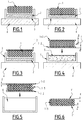
- the manufacture of the composite comprises the production of the BN (C) foam 1, then the protection of surface portions 1 'of the foam 1 by a protective material 2 ( Figures 1 to 3 ), in order to avoid the presence of MCP 5 on the surface, then the infusion of MCP 5 in foam 1 ( Figure 4 ) and finally the withdrawal of protection 2 ( Figure 5 ) to release the foam from the surface portions 1 '.
- a protective material 2 such as a polymer in solution in a solvent is prepared in order to obtain the desired viscosity (which influences the thickness E of the surface portion 1 'of the foam impregnated with said material 2) and limit the presence of bubbles during its solidification.
- the bubbles would make the material 2 fragile in places and would allow the penetration of the liquid MCP 5.
- This viscosity depends on the polymer as well as on its rate of dilution in a solvent.
- the protective material 2 is placed in a container 3 ( Figure 1 ) and the BN foam (C) 1 is deposited on said material 2 ( Figure 2 ).
- the whole is heated for example on a heating plate 4, until the material 2 forms a thin layer on the surface of the foam 1.
- the thickness E of the surface portion 1 'protected can be controlled thanks to the viscosity of the material. material 2.
- this operation can be carried out in the same way on another face of the BN foam (C).
- the MCP 5 is heated to pass to the liquid state.
- the protected foam 1 is immersed in an MCP 5 bath.
- the MCP 5 is allowed to infuse only the core of the foam 1 and then the foam thus impregnated is removed from the MCP 5 bath.
- the composite material obtained is left to cool so that the foam.
- MCP 5 turns solid.
- the shape of the mold for the MCP is arbitrarily square in the diagrams, but it can be modified to adapt to the constraints of the packaging and the application.
- the composite material is immersed in a bath of solvent 6 of the protective material 2, so as to dissolve the material 2, thus freeing each surface portion 1 'of the material 2.
- the composite material according to the invention can be prepared by selective etching of MCP.
- the manufacture of the composite firstly comprises the immersion of the continuous structure of BN (C) in a bath of MCP 5 contained in a container 3 placed on a heating plate 4.
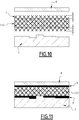
- the immersion is carried out entirely according to the second mode. of realization ( Figure 7 ).
- the material is extracted from the bath: it then consists of the structure of BN (C) impregnated over its entire thickness with MCP 5.
- the surface portions of the material thus obtained are then soaked in a bath of an etching solution 6 '. , allowing the MCP to dissolve on the submerged portions.
- the lower and upper faces can thus be immersed successively, to release two upper and lower surface portions 1 ′ of BN (C) devoid of MCP.
- the material can be completely submerged, this resulting in all the surface portions being clear of MCP, under all the faces of the material.
- a third embodiment can be represented by combining the steps of Figures 1-6 and 7-9 .
- the composite material thus formed can then be applied to an electronic component.
- the composite material is encapsulated between an aluminum cover 8 and an electronic component 7, such as for example a processor.
- Component 7 has an irregular relief on the surface. By compression, the surface portions 1 'of the composite material fill in the cavities and match the roughness of component 7.
- BN foam was prepared by applying the methodology described by Loeblein et al., Small, vol.10, n.15, 2992-2999, 2014 , without performing the carbon growth stage.
- PMMA is deposited just before the etching of the nickel in order to mechanically reinforce the BN. PMMA can be removed or stored after etching the nickel.
- Example 2 preparation of the composite
- the first strategy is to use a material that will protect the surfaces of the foam during the infusion. This protective material will then be removed.
- PEO Polyethylene Oxide
- the diluted polymer is stored under vacuum at approximately 2.5 mTorr for 30 min.
- the purpose of this “degassing” step is to remove air bubbles that have been trapped in the polymer during mixing. Without this step, during the densification phase air bubbles could form, damaging the foam and compromising the uniformity of the thickness of the polymer.
- the polymer is placed in an aluminum mold. The amount of polymer will depend on the dimensions of the mold, in order to have a polymer thickness of about 3 mm.
- the foam is deposited on the polymer which will slightly penetrate it. The depth of penetration will depend on the viscosity of the polymer.
- the mold is placed on a heating plate, in order to densify the polymer by evaporating the solvent (here water) gradually. It has been experimentally established that a step of 80 ° C for 40 min then an increase of 5 ° C every 5 min to reach 120 ° C is favorable. However, these temperatures and times depend on the hotplate temperature probe as well as the laboratory environment as everything is done in air.
- the foam with a protected face is removed from the mold. One side is perforated using a needle. These perforations are intended to aid in the infusion of the MCP thereafter and do little damage to the foam.
- the fifth step is identical to the third but on the opposite side of the foam.
- the paraffin is heated to 110 ° C, that is, slightly above the melting temperature of 90 ° C of the paraffin, in the aluminum mold.
- the foam with the two protected faces is immersed in it: the paraffin infiltrates on the sides but also through the perforated face which is kept above.
- the foam remains between 3 and 5 minutes in the MCP to ensure that the infusion is complete, while avoiding melting of the protective polymer. Finally it is put to cool, naturally or in a fridge to accelerate the cooling.
- the protected foam is immersed in water at room temperature.
- the compound is kept upright (so as not to damage the surfaces) in a beaker of water overnight.
- the water bath is renewed and left to act overnight to improve deprotection depending on the thickness of the polymer as well as the size of the sample and the amount of water. Finally, the sample is left to dry.
- Example 4 Preparation of the composite without protective material, by etching.
- the continuous structure of BN (C) is first infused by MCP in liquid phase at a temperature above the melting temperature of MCP. Then, the compound obtained is immersed in an ethanol bath at 65 ° C., allowing selective etching of the MCP with respect to the continuous structure. Each face of the MCP is etched at a speed of approximately 5 ⁇ m / min. One hour of bathing makes it possible to release approximately 300 ⁇ m of surface portion on each side of the compound. Then, the compound is immersed successively in several baths of ethanol at 65 ° C. for a few minutes to remove the re-deposits of MCP on the surface portions. Finally, the compound is dried in an oven at 50 ° C. for 1 hour.
- Example 5 Preparation of the composite with protective material and by etching.
- the continuous structure of BN (C) is surface infused with liquid NPG at a temperature of about 130 ° C on a hot plate.
- NPG infuses the continuous structure to a thickness of 1 to 2 mm.
- This step is repeated on the two opposite sides of the structure.
- the structure thus protected is immersed in the liquid MCP at 110 ° C. because its melting point is 90 ° C. for this example.
- the compound is immersed in an ethanol bath at 65 ° C.
- the NPG is dissolved almost instantaneously on the two protected faces releasing the surface portion to a thickness of 1 to 2 mm on these faces, the other faces are etched at a speed of approximately 5 ⁇ m / min. This makes it possible to have surface portions of different thickness.
- Example 6 manufacture of a component comprising the composite
- the invention can be applied in the case of a power transistor, dissipating for example 20 W, during a cyclic use, for example for a continuous operation of less than 15 min, with 15 min of cooling.
- the MCP is chosen according to the maximum critical temperature of the transistor: the melting temperature of the MCP must be equal to or less than that of the critical temperature of the transistor.
- the material according to the invention is applied directly to the transistor, with one of the stripped faces of the MCP in contact with the transistor to ensure good thermal contact. An encapsulation is carried out around the MCP as well as at the base of the processor to ensure the seal.
Landscapes
- Chemical & Material Sciences (AREA)
- Engineering & Computer Science (AREA)
- Ceramic Engineering (AREA)
- Materials Engineering (AREA)
- Organic Chemistry (AREA)
- Structural Engineering (AREA)
- Manufacturing & Machinery (AREA)
- Oil, Petroleum & Natural Gas (AREA)
- Civil Engineering (AREA)
- Inorganic Chemistry (AREA)
- Physics & Mathematics (AREA)
- Chemical Kinetics & Catalysis (AREA)
- Combustion & Propulsion (AREA)
- Thermal Sciences (AREA)
- Cooling Or The Like Of Semiconductors Or Solid State Devices (AREA)
- Superconductors And Manufacturing Methods Therefor (AREA)
- Ceramic Products (AREA)
Claims (13)
- Verbundwerkstoff, aufweisend:Bornitrid, das gegebenenfalls dotiert ist mit Kohlenstoff (BN(C)), in Form einer kontinuierlichen Struktur (1), so dass die kontinuierliche BN(C)-Struktur ein BN(C)-Schaum ist, und ein Phasenwechselmaterial (MCP) (5), das in die kontinuierliche BN(C)-Struktur (1) integriert ist, wobei das MCP aus Materialien ausgewählt ist, die in der Lage sind, einen fest/fest- oder fest/flüssig-Phasenübergang bei einer konstanten Temperatur durchzuführen,wobei das Verbundmaterial mindestens eine Fläche aufweist,und dadurch gekennzeichnet, dass das Verbundmaterial unter der Gesamtheit oder einem Teil der Fläche einen Oberflächenabschnitt (1') aufweist, der aus der kontinuierlichen BN(C)-Struktur (1) frei von MCP (5) gebildet ist.
- Verbundwerkstoff gemäß Anspruch 1, wobei der Oberflächenabschnitt eine Schicht mit einer Dicke E ungleich Null unter der Gesamtheit der Fläche ist.
- Verbundwerkstoff gemäß irgendeinem der vorhergehenden Ansprüche, wobei die kontinuierliche BN(C)-Struktur (1) eine kontinuierliche BNC-Struktur ist.
- Verbundwerkstoff gemäß irgendeinem der vorhergehenden Ansprüche, wobei der Verbundwerkstoff eine untere Fläche und eine obere Fläche aufweist, und wobei er unter jeder der beiden Flächen mindestens einen Oberflächenabschnitt (1') der kontinuierlichen Struktur frei von MCP (5) aufweist.
- Verbundwerkstoff gemäß irgendeinem der vorhergehenden Ansprüche, wobei der Verbundwerkstoff eine untere Fläche, eine obere Fläche und eine oder mehrere seitliche Flächen aufweist, wobei unter jeder dieser Flächen ein Oberflächenabschnitt (1') der kontinuierlichen BN(C)-Struktur frei von MCP (5) vorhanden ist.
- Verfahren zur Herstellung des Verbundwerkstoffs gemäß irgendeinem der vorhergehenden Ansprüche, wobei das Verfahren aufweist:- Infundieren von MCP in flüssiger Form in die kontinuierliche BN(C)-Struktur (1) und- Schützen/Entschützen des oder der Oberflächenabschnitte durch ein Schutzmaterial, das eine höhere Schmelztemperatur als die des MCP oder eine andere Ätzrate als die des MCP hat, und/oder Entfernen des gegebenenfalls in den oder die Oberflächenabschnitte infundierten MCP.
- Verfahren gemäß Anspruch 6, aufweisend die folgenden Schritte:- vorangehendes Schützen mindestens eines Oberflächenabschnitts (1') der kontinuierlichen BN(C)-Struktur (1) durch Imprägnieren mit einem Schutzmaterial,- Imprägnieren der kontinuierlichen BN(C)-Struktur (1) durch ein MCP (5) in flüssiger Form,- selektives Entschützen des oder der geschützten Abschnitte,wobei dadurch eine kontinuierliche BN(C)-Struktur gebildet wird, in die das MCP (5) integriert wird, mit Ausnahme des oder der Oberflächenabschnitte (1'), die frei von MCP sind.
- Verfahren gemäß Anspruch 7,
wobei das Imprägnieren durch das MCP (5) bei einer Temperatur, die größer ist als die Schmelztemperatur des MCP (5) und entweder kleiner ist als die Schmelztemperatur des Schutzmaterials oder bei einer Temperatur, die eine Schmelzdauer des Schutzmaterials erzeugt, die kleiner ist als die Infusionszeit des MCP (2), durchgeführt wird. - Verfahren gemäß Anspruch 7 oder 8,
wobei das Schutzmaterial eine Schmelztemperatur hat, die größer als die Schmelztemperatur des MCP ist. - Verfahren gemäß Anspruch 6, aufweisend die folgenden Schritte:- Imprägnieren der kontinuierlichen BN(C)-Struktur (1) durch ein MCP (5) in flüssiger Form,- selektives Ätzen des MCP innerhalb mindestens eines Oberflächenabschnitts (1').
- Verfahren gemäß Anspruch 6, aufweisend:- vorangehendes Schützen mindestens eines Oberflächenabschnitts (1') der kontinuierlichen BN(C)-Struktur (1) durch ein Schutzmaterial mit einer Ätzrate, die sich von der des MCP unterscheidet,- Imprägnieren der kontinuierlichen BN(C)-Struktur (1) durch ein MCP (5) in flüssiger Form, und- Ätzen des MCP durch Eintauchen des oder der mit dem Material imprägnierten Oberflächenbereiche (1') in ein Ätzlösungsmittel.
- Elektronisches Bauelement (7), aufweisend einen Verbundwerkstoff gemäß irgendeinem der Ansprüche 1 bis 5.
- Verfahren gemäß Anspruch 6 zum Herstellen des Bauelements (7) gemäß Anspruch 12, aufweisend den Schritt des Aufbringens des Verbundwerkstoffs auf das Bauelement (7).
Applications Claiming Priority (2)
| Application Number | Priority Date | Filing Date | Title |
|---|---|---|---|
| FR1700516A FR3066490B1 (fr) | 2017-05-16 | 2017-05-16 | Materiau thermique a haute capacite et haute conductivite, son procede de preparation et les composants le comprenant |
| PCT/EP2018/062780 WO2018210950A1 (fr) | 2017-05-16 | 2018-05-16 | Matériau thermique à haute capacité et haute conductivité, son procédé de préparation et les composants le comprenant |
Publications (2)
| Publication Number | Publication Date |
|---|---|
| EP3625193A1 EP3625193A1 (de) | 2020-03-25 |
| EP3625193B1 true EP3625193B1 (de) | 2021-06-09 |
Family
ID=59974480
Family Applications (1)
| Application Number | Title | Priority Date | Filing Date |
|---|---|---|---|
| EP18723544.5A Active EP3625193B1 (de) | 2017-05-16 | 2018-05-16 | Thermisches material mit hoher kapazität und hoher leitfähigkeit, verfahren zu dessen herstellung und von komponenten damit |
Country Status (6)
| Country | Link |
|---|---|
| US (1) | US20200115286A1 (de) |
| EP (1) | EP3625193B1 (de) |
| AU (1) | AU2018269662B2 (de) |
| ES (1) | ES2878291T3 (de) |
| FR (1) | FR3066490B1 (de) |
| WO (1) | WO2018210950A1 (de) |
Families Citing this family (3)
| Publication number | Priority date | Publication date | Assignee | Title |
|---|---|---|---|---|
| CN114007370B (zh) * | 2020-07-27 | 2024-12-06 | 杜邦电子公司 | 用于电子设备的散热器 |
| KR102945995B1 (ko) | 2020-07-27 | 2026-04-01 | 듀폰 일렉트로닉스, 인크. | 전자 장치용 히트 싱크 |
| WO2022076063A2 (en) * | 2020-07-31 | 2022-04-14 | Georgia Tech Research Corporation | Methods and systems for reconfigurable hybrid metasurfaces |
Family Cites Families (4)
| Publication number | Priority date | Publication date | Assignee | Title |
|---|---|---|---|---|
| US6621702B2 (en) * | 2002-01-25 | 2003-09-16 | Lockheed Martin Corporation | Method and apparatus for absorbing thermal energy |
| US9534855B2 (en) * | 2014-11-20 | 2017-01-03 | General Electric Company | High specific area composite foam and an associated method of fabrication |
| CN106497522A (zh) * | 2016-10-21 | 2017-03-15 | 中南大学 | 一种泡沫金刚石增强石蜡相变储能材料及制备方法 |
| CN105733192B (zh) * | 2016-03-21 | 2018-05-04 | 中南大学 | 一种泡沫骨架增强聚合物基复合材料及其制备方法 |
-
2017
- 2017-05-16 FR FR1700516A patent/FR3066490B1/fr not_active Expired - Fee Related
-
2018
- 2018-05-16 US US16/612,701 patent/US20200115286A1/en not_active Abandoned
- 2018-05-16 EP EP18723544.5A patent/EP3625193B1/de active Active
- 2018-05-16 WO PCT/EP2018/062780 patent/WO2018210950A1/fr not_active Ceased
- 2018-05-16 AU AU2018269662A patent/AU2018269662B2/en active Active
- 2018-05-16 ES ES18723544T patent/ES2878291T3/es active Active
Non-Patent Citations (1)
| Title |
|---|
| JIE YANG ET AL: "An ice-templated assembly strategy to construct graphene oxide/boron nitride hybrid porous scaffolds in phase change materials with enhanced thermal conductivity and shape stability for light-thermal-electric energy conversion", JOURNAL OF MATERIALS CHEMISTRY A, vol. 4, no. 48, 9 November 2016 (2016-11-09), GB, pages 18841 - 18851, XP055499904, ISSN: 2050-7488, DOI: 10.1039/C6TA08454K * |
Also Published As
| Publication number | Publication date |
|---|---|
| AU2018269662B2 (en) | 2023-01-12 |
| WO2018210950A1 (fr) | 2018-11-22 |
| EP3625193A1 (de) | 2020-03-25 |
| ES2878291T3 (es) | 2021-11-18 |
| AU2018269662A1 (en) | 2019-11-28 |
| FR3066490A1 (fr) | 2018-11-23 |
| US20200115286A1 (en) | 2020-04-16 |
| FR3066490B1 (fr) | 2021-08-06 |
Similar Documents
| Publication | Publication Date | Title |
|---|---|---|
| EP3728163B1 (de) | Verbessertes wärmematerial mit hoher kapazität und hoher leitfähigkeit, verfahren zur herstellung davon und komponenten damit | |
| EP1594816B1 (de) | Verfahren zur silizierung von thermostrukturellen verbundwerkstoffen und so hergestellte teile | |
| EP3625193B1 (de) | Thermisches material mit hoher kapazität und hoher leitfähigkeit, verfahren zu dessen herstellung und von komponenten damit | |
| EP3275037B1 (de) | Poröse elektrolytmembran, herstellungsverfahren dafür und elektrochemische vorrichtungen damit | |
| EP3420583A1 (de) | Träger für eine halbleiterstruktur | |
| EP1602143B1 (de) | Wiederaufladbarer elektrochemischer akku | |
| FR3060840A1 (fr) | Procede de realisation d'un dispositif semi-conducteur a espaceurs internes auto-alignes | |
| WO2013104620A1 (fr) | Dispositif de gestion thermique passif | |
| FR2942073A1 (fr) | Procede de realisation d'une couche de cavites | |
| WO2016075290A2 (fr) | Structure composite comportant une resine chargee avec des feuillets plans de graphene a conductivite thermique et conductivite electrique renforcees, notamment pour satellite | |
| FR3007892A1 (fr) | Procede de transfert d'une couche mince avec apport d'energie thermique a une zone fragilisee via une couche inductive | |
| EP0660400B1 (de) | In der Elektronik als Träger gedruckter Schaltungen oder Bauelemente verwendbares Wärmeleitungselement und Herstellungsverfahren dafür | |
| FR3047352A1 (fr) | Procede de fabrication d'un transistor a dopant localise a l'aplomb de la grille | |
| WO2002058134A1 (fr) | Procede de fabrication de reseaux d'interconnexions | |
| EP3876330B1 (de) | Verfahren zur herstellung einer elektrolyt-membran | |
| WO2024022723A1 (fr) | Procédé de préparation d'une couche mince monodomaine en matériau ferroélectrique comprenant du lithium | |
| FR2848334A1 (fr) | Procede de fabrication d'une structure multicouche | |
| FR2873488A1 (fr) | FIL SUPRACONDUCTEUR A PHASE Nb-Sn ET PRECURSEUR POUR CE FIL | |
| WO2020152284A1 (fr) | Procédé de fabrication d'une pièce composite à matrice céramique, pièce composite, et composant électrique correspondants | |
| JP5253562B2 (ja) | 半導体積層体及びその製造方法 | |
| WO2025153203A1 (fr) | Support comprenant une couche de piegeage de charges electriques pour un substrat composite | |
| EP4640023A1 (de) | Verfahren zur herstellung einer eindomänen-dünnschicht aus ferroelektrischem material mit lithium | |
| WO2024121504A1 (fr) | Procédé de fabrication d'un substrat pour un dispositif électronique de puissance ou radiofréquence | |
| WO2023194682A1 (fr) | Substrat pour dispositif électronique | |
| WO2023078728A1 (fr) | Chambre à vapeur |
Legal Events
| Date | Code | Title | Description |
|---|---|---|---|
| STAA | Information on the status of an ep patent application or granted ep patent |
Free format text: STATUS: UNKNOWN |
|
| STAA | Information on the status of an ep patent application or granted ep patent |
Free format text: STATUS: THE INTERNATIONAL PUBLICATION HAS BEEN MADE |
|
| PUAI | Public reference made under article 153(3) epc to a published international application that has entered the european phase |
Free format text: ORIGINAL CODE: 0009012 |
|
| STAA | Information on the status of an ep patent application or granted ep patent |
Free format text: STATUS: REQUEST FOR EXAMINATION WAS MADE |
|
| 17P | Request for examination filed |
Effective date: 20191114 |
|
| AK | Designated contracting states |
Kind code of ref document: A1 Designated state(s): AL AT BE BG CH CY CZ DE DK EE ES FI FR GB GR HR HU IE IS IT LI LT LU LV MC MK MT NL NO PL PT RO RS SE SI SK SM TR |
|
| AX | Request for extension of the european patent |
Extension state: BA ME |
|
| DAV | Request for validation of the european patent (deleted) | ||
| DAX | Request for extension of the european patent (deleted) | ||
| REG | Reference to a national code |
Ref country code: DE Ref legal event code: R079 Ref document number: 602018018405 Country of ref document: DE Free format text: PREVIOUS MAIN CLASS: C04B0035583000 Ipc: C04B0041000000 |
|
| RIC1 | Information provided on ipc code assigned before grant |
Ipc: C09K 5/06 20060101ALI20201113BHEP Ipc: C04B 35/583 20060101ALI20201113BHEP Ipc: C04B 38/04 20060101ALI20201113BHEP Ipc: C04B 41/00 20060101AFI20201113BHEP Ipc: C04B 41/47 20060101ALI20201113BHEP Ipc: C04B 41/45 20060101ALI20201113BHEP Ipc: C04B 35/632 20060101ALI20201113BHEP Ipc: C04B 41/82 20060101ALI20201113BHEP |
|
| GRAP | Despatch of communication of intention to grant a patent |
Free format text: ORIGINAL CODE: EPIDOSNIGR1 |
|
| STAA | Information on the status of an ep patent application or granted ep patent |
Free format text: STATUS: GRANT OF PATENT IS INTENDED |
|
| INTG | Intention to grant announced |
Effective date: 20210113 |
|
| RIN1 | Information on inventor provided before grant (corrected) |
Inventor name: TEO, EDWIN, HANG TONG Inventor name: COQUET, PHILIPPE Inventor name: PAWLIK, MATTHIEU Inventor name: TSANG, TONY, SIU HON Inventor name: LOEBLEIN, MANUELA Inventor name: FONCIN, JEROME Inventor name: MERLET, THOMAS |
|
| GRAS | Grant fee paid |
Free format text: ORIGINAL CODE: EPIDOSNIGR3 |
|
| GRAA | (expected) grant |
Free format text: ORIGINAL CODE: 0009210 |
|
| STAA | Information on the status of an ep patent application or granted ep patent |
Free format text: STATUS: THE PATENT HAS BEEN GRANTED |
|
| AK | Designated contracting states |
Kind code of ref document: B1 Designated state(s): AL AT BE BG CH CY CZ DE DK EE ES FI FR GB GR HR HU IE IS IT LI LT LU LV MC MK MT NL NO PL PT RO RS SE SI SK SM TR |
|
| REG | Reference to a national code |
Ref country code: GB Ref legal event code: FG4D Free format text: NOT ENGLISH |
|
| REG | Reference to a national code |
Ref country code: CH Ref legal event code: EP Ref country code: AT Ref legal event code: REF Ref document number: 1400382 Country of ref document: AT Kind code of ref document: T Effective date: 20210615 |
|
| REG | Reference to a national code |
Ref country code: DE Ref legal event code: R096 Ref document number: 602018018405 Country of ref document: DE |
|
| REG | Reference to a national code |
Ref country code: IE Ref legal event code: FG4D Free format text: LANGUAGE OF EP DOCUMENT: FRENCH |
|
| REG | Reference to a national code |
Ref country code: SE Ref legal event code: TRGR |
|
| REG | Reference to a national code |
Ref country code: LT Ref legal event code: MG9D |
|
| PG25 | Lapsed in a contracting state [announced via postgrant information from national office to epo] |
Ref country code: FI Free format text: LAPSE BECAUSE OF FAILURE TO SUBMIT A TRANSLATION OF THE DESCRIPTION OR TO PAY THE FEE WITHIN THE PRESCRIBED TIME-LIMIT Effective date: 20210609 Ref country code: HR Free format text: LAPSE BECAUSE OF FAILURE TO SUBMIT A TRANSLATION OF THE DESCRIPTION OR TO PAY THE FEE WITHIN THE PRESCRIBED TIME-LIMIT Effective date: 20210609 Ref country code: LT Free format text: LAPSE BECAUSE OF FAILURE TO SUBMIT A TRANSLATION OF THE DESCRIPTION OR TO PAY THE FEE WITHIN THE PRESCRIBED TIME-LIMIT Effective date: 20210609 Ref country code: BG Free format text: LAPSE BECAUSE OF FAILURE TO SUBMIT A TRANSLATION OF THE DESCRIPTION OR TO PAY THE FEE WITHIN THE PRESCRIBED TIME-LIMIT Effective date: 20210909 |
|
| REG | Reference to a national code |
Ref country code: AT Ref legal event code: MK05 Ref document number: 1400382 Country of ref document: AT Kind code of ref document: T Effective date: 20210609 |
|
| REG | Reference to a national code |
Ref country code: NL Ref legal event code: MP Effective date: 20210609 |
|
| REG | Reference to a national code |
Ref country code: ES Ref legal event code: FG2A Ref document number: 2878291 Country of ref document: ES Kind code of ref document: T3 Effective date: 20211118 |
|
| PG25 | Lapsed in a contracting state [announced via postgrant information from national office to epo] |
Ref country code: GR Free format text: LAPSE BECAUSE OF FAILURE TO SUBMIT A TRANSLATION OF THE DESCRIPTION OR TO PAY THE FEE WITHIN THE PRESCRIBED TIME-LIMIT Effective date: 20210910 Ref country code: NO Free format text: LAPSE BECAUSE OF FAILURE TO SUBMIT A TRANSLATION OF THE DESCRIPTION OR TO PAY THE FEE WITHIN THE PRESCRIBED TIME-LIMIT Effective date: 20210909 Ref country code: LV Free format text: LAPSE BECAUSE OF FAILURE TO SUBMIT A TRANSLATION OF THE DESCRIPTION OR TO PAY THE FEE WITHIN THE PRESCRIBED TIME-LIMIT Effective date: 20210609 Ref country code: RS Free format text: LAPSE BECAUSE OF FAILURE TO SUBMIT A TRANSLATION OF THE DESCRIPTION OR TO PAY THE FEE WITHIN THE PRESCRIBED TIME-LIMIT Effective date: 20210609 |
|
| PG25 | Lapsed in a contracting state [announced via postgrant information from national office to epo] |
Ref country code: CZ Free format text: LAPSE BECAUSE OF FAILURE TO SUBMIT A TRANSLATION OF THE DESCRIPTION OR TO PAY THE FEE WITHIN THE PRESCRIBED TIME-LIMIT Effective date: 20210609 Ref country code: AT Free format text: LAPSE BECAUSE OF FAILURE TO SUBMIT A TRANSLATION OF THE DESCRIPTION OR TO PAY THE FEE WITHIN THE PRESCRIBED TIME-LIMIT Effective date: 20210609 Ref country code: SM Free format text: LAPSE BECAUSE OF FAILURE TO SUBMIT A TRANSLATION OF THE DESCRIPTION OR TO PAY THE FEE WITHIN THE PRESCRIBED TIME-LIMIT Effective date: 20210609 Ref country code: NL Free format text: LAPSE BECAUSE OF FAILURE TO SUBMIT A TRANSLATION OF THE DESCRIPTION OR TO PAY THE FEE WITHIN THE PRESCRIBED TIME-LIMIT Effective date: 20210609 Ref country code: RO Free format text: LAPSE BECAUSE OF FAILURE TO SUBMIT A TRANSLATION OF THE DESCRIPTION OR TO PAY THE FEE WITHIN THE PRESCRIBED TIME-LIMIT Effective date: 20210609 Ref country code: PT Free format text: LAPSE BECAUSE OF FAILURE TO SUBMIT A TRANSLATION OF THE DESCRIPTION OR TO PAY THE FEE WITHIN THE PRESCRIBED TIME-LIMIT Effective date: 20211011 Ref country code: EE Free format text: LAPSE BECAUSE OF FAILURE TO SUBMIT A TRANSLATION OF THE DESCRIPTION OR TO PAY THE FEE WITHIN THE PRESCRIBED TIME-LIMIT Effective date: 20210609 Ref country code: SK Free format text: LAPSE BECAUSE OF FAILURE TO SUBMIT A TRANSLATION OF THE DESCRIPTION OR TO PAY THE FEE WITHIN THE PRESCRIBED TIME-LIMIT Effective date: 20210609 |
|
| PG25 | Lapsed in a contracting state [announced via postgrant information from national office to epo] |
Ref country code: PL Free format text: LAPSE BECAUSE OF FAILURE TO SUBMIT A TRANSLATION OF THE DESCRIPTION OR TO PAY THE FEE WITHIN THE PRESCRIBED TIME-LIMIT Effective date: 20210609 |
|
| REG | Reference to a national code |
Ref country code: DE Ref legal event code: R097 Ref document number: 602018018405 Country of ref document: DE |
|
| PLBE | No opposition filed within time limit |
Free format text: ORIGINAL CODE: 0009261 |
|
| STAA | Information on the status of an ep patent application or granted ep patent |
Free format text: STATUS: NO OPPOSITION FILED WITHIN TIME LIMIT |
|
| PG25 | Lapsed in a contracting state [announced via postgrant information from national office to epo] |
Ref country code: DK Free format text: LAPSE BECAUSE OF FAILURE TO SUBMIT A TRANSLATION OF THE DESCRIPTION OR TO PAY THE FEE WITHIN THE PRESCRIBED TIME-LIMIT Effective date: 20210609 |
|
| 26N | No opposition filed |
Effective date: 20220310 |
|
| PG25 | Lapsed in a contracting state [announced via postgrant information from national office to epo] |
Ref country code: AL Free format text: LAPSE BECAUSE OF FAILURE TO SUBMIT A TRANSLATION OF THE DESCRIPTION OR TO PAY THE FEE WITHIN THE PRESCRIBED TIME-LIMIT Effective date: 20210609 |
|
| REG | Reference to a national code |
Ref country code: CH Ref legal event code: PL |
|
| REG | Reference to a national code |
Ref country code: BE Ref legal event code: MM Effective date: 20220531 |
|
| PG25 | Lapsed in a contracting state [announced via postgrant information from national office to epo] |
Ref country code: MC Free format text: LAPSE BECAUSE OF FAILURE TO SUBMIT A TRANSLATION OF THE DESCRIPTION OR TO PAY THE FEE WITHIN THE PRESCRIBED TIME-LIMIT Effective date: 20210609 Ref country code: LU Free format text: LAPSE BECAUSE OF NON-PAYMENT OF DUE FEES Effective date: 20220516 Ref country code: LI Free format text: LAPSE BECAUSE OF NON-PAYMENT OF DUE FEES Effective date: 20220531 Ref country code: CH Free format text: LAPSE BECAUSE OF NON-PAYMENT OF DUE FEES Effective date: 20220531 |
|
| PG25 | Lapsed in a contracting state [announced via postgrant information from national office to epo] |
Ref country code: IE Free format text: LAPSE BECAUSE OF NON-PAYMENT OF DUE FEES Effective date: 20220516 |
|
| PG25 | Lapsed in a contracting state [announced via postgrant information from national office to epo] |
Ref country code: BE Free format text: LAPSE BECAUSE OF NON-PAYMENT OF DUE FEES Effective date: 20220531 |
|
| PG25 | Lapsed in a contracting state [announced via postgrant information from national office to epo] |
Ref country code: MK Free format text: LAPSE BECAUSE OF FAILURE TO SUBMIT A TRANSLATION OF THE DESCRIPTION OR TO PAY THE FEE WITHIN THE PRESCRIBED TIME-LIMIT Effective date: 20210609 Ref country code: CY Free format text: LAPSE BECAUSE OF FAILURE TO SUBMIT A TRANSLATION OF THE DESCRIPTION OR TO PAY THE FEE WITHIN THE PRESCRIBED TIME-LIMIT Effective date: 20210609 |
|
| PG25 | Lapsed in a contracting state [announced via postgrant information from national office to epo] |
Ref country code: HU Free format text: LAPSE BECAUSE OF FAILURE TO SUBMIT A TRANSLATION OF THE DESCRIPTION OR TO PAY THE FEE WITHIN THE PRESCRIBED TIME-LIMIT; INVALID AB INITIO Effective date: 20180516 |
|
| PG25 | Lapsed in a contracting state [announced via postgrant information from national office to epo] |
Ref country code: TR Free format text: LAPSE BECAUSE OF FAILURE TO SUBMIT A TRANSLATION OF THE DESCRIPTION OR TO PAY THE FEE WITHIN THE PRESCRIBED TIME-LIMIT Effective date: 20210609 |
|
| PG25 | Lapsed in a contracting state [announced via postgrant information from national office to epo] |
Ref country code: MT Free format text: LAPSE BECAUSE OF FAILURE TO SUBMIT A TRANSLATION OF THE DESCRIPTION OR TO PAY THE FEE WITHIN THE PRESCRIBED TIME-LIMIT Effective date: 20210609 |
|
| PGFP | Annual fee paid to national office [announced via postgrant information from national office to epo] |
Ref country code: DE Payment date: 20250513 Year of fee payment: 8 |
|
| PGFP | Annual fee paid to national office [announced via postgrant information from national office to epo] |
Ref country code: ES Payment date: 20250610 Year of fee payment: 8 Ref country code: GB Payment date: 20250521 Year of fee payment: 8 |
|
| PGFP | Annual fee paid to national office [announced via postgrant information from national office to epo] |
Ref country code: IT Payment date: 20250508 Year of fee payment: 8 |
|
| PGFP | Annual fee paid to national office [announced via postgrant information from national office to epo] |
Ref country code: FR Payment date: 20250530 Year of fee payment: 8 |
|
| PGFP | Annual fee paid to national office [announced via postgrant information from national office to epo] |
Ref country code: SE Payment date: 20250519 Year of fee payment: 8 |