EP3625423B1 - Fensterrahmen mit einer gitterträgerstruktur - Google Patents
Fensterrahmen mit einer gitterträgerstruktur Download PDFInfo
- Publication number
- EP3625423B1 EP3625423B1 EP18728458.3A EP18728458A EP3625423B1 EP 3625423 B1 EP3625423 B1 EP 3625423B1 EP 18728458 A EP18728458 A EP 18728458A EP 3625423 B1 EP3625423 B1 EP 3625423B1
- Authority
- EP
- European Patent Office
- Prior art keywords
- crosspiece
- elongated structure
- window frame
- elongated
- abutment surface
- Prior art date
- Legal status (The legal status is an assumption and is not a legal conclusion. Google has not performed a legal analysis and makes no representation as to the accuracy of the status listed.)
- Active
Links
- 239000004411 aluminium Substances 0.000 claims description 8
- 229910052782 aluminium Inorganic materials 0.000 claims description 8
- XAGFODPZIPBFFR-UHFFFAOYSA-N aluminium Chemical compound [Al] XAGFODPZIPBFFR-UHFFFAOYSA-N 0.000 claims description 8
- XEEYBQQBJWHFJM-UHFFFAOYSA-N Iron Chemical compound [Fe] XEEYBQQBJWHFJM-UHFFFAOYSA-N 0.000 claims description 4
- 229910001369 Brass Inorganic materials 0.000 claims description 2
- 229910000906 Bronze Inorganic materials 0.000 claims description 2
- RYGMFSIKBFXOCR-UHFFFAOYSA-N Copper Chemical compound [Cu] RYGMFSIKBFXOCR-UHFFFAOYSA-N 0.000 claims description 2
- 239000010951 brass Substances 0.000 claims description 2
- 239000010974 bronze Substances 0.000 claims description 2
- 239000010949 copper Substances 0.000 claims description 2
- 229910052802 copper Inorganic materials 0.000 claims description 2
- KUNSUQLRTQLHQQ-UHFFFAOYSA-N copper tin Chemical compound [Cu].[Sn] KUNSUQLRTQLHQQ-UHFFFAOYSA-N 0.000 claims description 2
- 229910052742 iron Inorganic materials 0.000 claims description 2
- 239000010935 stainless steel Substances 0.000 claims description 2
- 229910001220 stainless steel Inorganic materials 0.000 claims description 2
- 239000007769 metal material Substances 0.000 claims 1
- 238000004088 simulation Methods 0.000 description 16
- 239000011521 glass Substances 0.000 description 15
- 239000000463 material Substances 0.000 description 13
- 239000011295 pitch Substances 0.000 description 13
- 238000009413 insulation Methods 0.000 description 9
- 239000002184 metal Substances 0.000 description 8
- 229910052751 metal Inorganic materials 0.000 description 8
- 239000002023 wood Substances 0.000 description 8
- 238000003466 welding Methods 0.000 description 7
- 238000013461 design Methods 0.000 description 6
- 125000006850 spacer group Chemical group 0.000 description 6
- 239000013598 vector Substances 0.000 description 6
- 230000008901 benefit Effects 0.000 description 5
- 238000005259 measurement Methods 0.000 description 5
- 238000011161 development Methods 0.000 description 4
- 229920000915 polyvinyl chloride Polymers 0.000 description 4
- 239000004800 polyvinyl chloride Substances 0.000 description 4
- 230000005540 biological transmission Effects 0.000 description 3
- 229920000642 polymer Polymers 0.000 description 3
- 229910000831 Steel Inorganic materials 0.000 description 2
- 238000005452 bending Methods 0.000 description 2
- 238000010276 construction Methods 0.000 description 2
- 238000005516 engineering process Methods 0.000 description 2
- 230000006872 improvement Effects 0.000 description 2
- 238000000034 method Methods 0.000 description 2
- 238000012986 modification Methods 0.000 description 2
- 230000004048 modification Effects 0.000 description 2
- 230000002787 reinforcement Effects 0.000 description 2
- 239000010959 steel Substances 0.000 description 2
- 230000001154 acute effect Effects 0.000 description 1
- 230000003321 amplification Effects 0.000 description 1
- 230000008859 change Effects 0.000 description 1
- 239000003795 chemical substances by application Substances 0.000 description 1
- 230000006835 compression Effects 0.000 description 1
- 238000007906 compression Methods 0.000 description 1
- 238000012790 confirmation Methods 0.000 description 1
- 238000005520 cutting process Methods 0.000 description 1
- 230000006866 deterioration Effects 0.000 description 1
- 230000010339 dilation Effects 0.000 description 1
- 239000006185 dispersion Substances 0.000 description 1
- 230000000694 effects Effects 0.000 description 1
- 238000009434 installation Methods 0.000 description 1
- 239000011810 insulating material Substances 0.000 description 1
- 238000011835 investigation Methods 0.000 description 1
- 238000005304 joining Methods 0.000 description 1
- 238000003698 laser cutting Methods 0.000 description 1
- 238000004519 manufacturing process Methods 0.000 description 1
- 238000003199 nucleic acid amplification method Methods 0.000 description 1
- 229920001296 polysiloxane Polymers 0.000 description 1
- 238000012545 processing Methods 0.000 description 1
- 238000007789 sealing Methods 0.000 description 1
- 238000000926 separation method Methods 0.000 description 1
Images


Classifications
-
- E—FIXED CONSTRUCTIONS
- E06—DOORS, WINDOWS, SHUTTERS, OR ROLLER BLINDS IN GENERAL; LADDERS
- E06B—FIXED OR MOVABLE CLOSURES FOR OPENINGS IN BUILDINGS, VEHICLES, FENCES OR LIKE ENCLOSURES IN GENERAL, e.g. DOORS, WINDOWS, BLINDS, GATES
- E06B3/00—Window sashes, door leaves, or like elements for closing wall or like openings; Layout of fixed or moving closures, e.g. windows in wall or like openings; Features of rigidly-mounted outer frames relating to the mounting of wing frames
- E06B3/04—Wing frames not characterised by the manner of movement
- E06B3/06—Single frames
- E06B3/08—Constructions depending on the use of specified materials
- E06B3/12—Constructions depending on the use of specified materials of metal
-
- E—FIXED CONSTRUCTIONS
- E06—DOORS, WINDOWS, SHUTTERS, OR ROLLER BLINDS IN GENERAL; LADDERS
- E06B—FIXED OR MOVABLE CLOSURES FOR OPENINGS IN BUILDINGS, VEHICLES, FENCES OR LIKE ENCLOSURES IN GENERAL, e.g. DOORS, WINDOWS, BLINDS, GATES
- E06B3/00—Window sashes, door leaves, or like elements for closing wall or like openings; Layout of fixed or moving closures, e.g. windows in wall or like openings; Features of rigidly-mounted outer frames relating to the mounting of wing frames
- E06B3/04—Wing frames not characterised by the manner of movement
- E06B3/263—Frames with special provision for insulation
- E06B3/2634—Frames with special provision for insulation without separate insulating elements, e.g. the heat transmission being reduced by a smaller cross-section
-
- E—FIXED CONSTRUCTIONS
- E06—DOORS, WINDOWS, SHUTTERS, OR ROLLER BLINDS IN GENERAL; LADDERS
- E06B—FIXED OR MOVABLE CLOSURES FOR OPENINGS IN BUILDINGS, VEHICLES, FENCES OR LIKE ENCLOSURES IN GENERAL, e.g. DOORS, WINDOWS, BLINDS, GATES
- E06B3/00—Window sashes, door leaves, or like elements for closing wall or like openings; Layout of fixed or moving closures, e.g. windows in wall or like openings; Features of rigidly-mounted outer frames relating to the mounting of wing frames
- E06B3/54—Fixing of glass panes or like plates
- E06B3/549—Fixing of glass panes or like plates by clamping the pane between two subframes
-
- E—FIXED CONSTRUCTIONS
- E06—DOORS, WINDOWS, SHUTTERS, OR ROLLER BLINDS IN GENERAL; LADDERS
- E06B—FIXED OR MOVABLE CLOSURES FOR OPENINGS IN BUILDINGS, VEHICLES, FENCES OR LIKE ENCLOSURES IN GENERAL, e.g. DOORS, WINDOWS, BLINDS, GATES
- E06B3/00—Window sashes, door leaves, or like elements for closing wall or like openings; Layout of fixed or moving closures, e.g. windows in wall or like openings; Features of rigidly-mounted outer frames relating to the mounting of wing frames
- E06B3/54—Fixing of glass panes or like plates
- E06B3/58—Fixing of glass panes or like plates by means of borders, cleats, or the like
- E06B3/585—Fixing of glass panes or like plates by means of borders, cleats, or the like adjustable, e.g. for accommodating panes of various thickness, or with provisions for altering the clamping force on the pane
- E06B3/5857—Fixing of glass panes or like plates by means of borders, cleats, or the like adjustable, e.g. for accommodating panes of various thickness, or with provisions for altering the clamping force on the pane the fixing being adjustable, e.g. in one of several possible positions
Definitions
- the present invention relates to a metal window frame, in particular for installation in buildings used as dwellings, offices, commercial establishments, and the like.
- window frames are provided which are suitable for holding, in a fixed or movable way, panels for closing the same openings.
- the window frames provided with glass panels are widely appreciated because they allow the passage of light even when they are completely closed.
- a first problem is of mainly structural type and relates to the need for the window frame as a whole to be able to withstand stresses to which it will be subject during its service life. Stresses to be taken into consideration are of various type: the weight force of glasses, stresses which may derive from thermal dilation and the force resulting from pressure exerted by the wind. In the case of the latter, the resultant force may be either positive (that is, deriving from a pressure acting from the outside, perpendicularly to the glass surface) or, more rarely, negative (that is, deriving from a depression on the glass surface). Between the two load conditions, the heaviest is the first and the window frame must be designed based on it, in order to guarantee the necessary structural resistance.
- insulation improvement is obtained by insulating glasses (with double or triple glass panels) and/or athermal glasses and/or screened glasses.
- a first type of window frames that solves this problem is that of the window frames entirely made of a material with low thermal conductivity, typically PVC (polyvinylchloride) or wood.
- PVC polyvinylchloride
- wood unlike wood, PVC is usually not able to perform the required structural functions and must therefore be reinforced with metal profiles set up in appropriate cavities.
- Wood on the other hand, besides having a low thermal conductivity, also has good mechanical features.
- a second type of window frames that solves this problem is that of the window frames having a metal structure and with the so-called thermal break.
- the metal structure of the window frame is not continuous but it is interrupted by an insulating diaphragm.
- the portion visible from inside the dwelling is separated from the portion visible from the outside of the dwelling. Separation is obtained by means of a diaphragm made of a material with low thermal conductivity.
- the metal structure of the window frame is made of aluminium profiles, while the insulating diaphragm is made of polymer. In this way it is possible to avoid a large part of heat transmission through the window frame itself. Note how the interposition of a diaphragm made of polymer interrupts the structural continuity of the window frame by introducing a point of weakness. The overall design of the window frame must therefore take into account the polymer diaphragm.
- a further type of window frame provides that a portion, usually the one intended to be turned inward, is made of wood, while another portion, usually the one intended to be turned towards the outside, is made of aluminium.
- the object of the present invention is to overcome the drawbacks of the known art highlighted above
- An elongated structure according to the preamble of claim 1 is already known from document WO 00/65172 A1 .
- a task of the present invention is that of making available a window frame structure that has at the same time a reduced cross-section, excellent thermal insulation features and the mechanical features needed to withstand the design loads.
- a task of the present invention is that of making available a window frame and a window made with the window frame structure having the above-described features.
- 'internal' and 'external' refer to a correctly fitted window frame to divide the interior from the outside of a building.
- the window frame according to the invention could also be assembled completely inside a building, for example to separate two internal spaces, or completely outside. In these cases, however, some of the technical features of the window frame would be superfluous.
- the term 'elongated structure' indicates the basic element of the window frame, having a prevalent development along an axis.
- the elongated structure is intended to be connected to other elongated structures.
- 'window frame' means a plurality of elongated structures connected to each other, so as to support a panel.
- 'window' indicates a window frame provided with the relative panel.
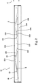
- the invention relates, first of all, to an elongated structure 20 for a window frame 200 suitable for supporting a panel 19 for separating an inner environment from an outer environment.
- the elongated structure 20 comprises:
- the truss structure 23 comprises rods 230 extending from connection zones 213 of the first crosspiece 21 to connection zones 223 of the second crosspiece 22.
- the rods 230 are tapered.
- the first abutment surface 211 is spaced from the second abutment surface 222 by a distance d; preferably the distance d is comprised between 25 mm and 82 mm.
- each rod 230 comprises an outer edge 231, facing the first crosspiece 21, and an inner edge 232, facing the second crosspiece 22; preferably in each rod 230, the shorter one among the outer edge 231 and the inner edge 232 is at least 100 mm long.
- each rod 230 defines a minimum cross section; preferably the minimum cross section has an extension s such that t ⁇ s ⁇ 2t.
- part of the accessory technical features of the elongated structure 20 of the window frame 200 are expressed through some parameters: the distance d between the abutment surfaces 211 and 222; the length of the shortest between the outer edge 231 and the inner edge 232 of each rod 230; the pitches p1 and p2 between the connection zones 213 and 223 of the crosspieces 21 and 22; and the extension s of the minimum cross section of each rod 230. Further details regarding these parameters will be shown below.
- the first abutment surface 211 defined by the first crosspiece 21 and the second abutment surface 222 defined by the second crosspiece 22 develop in parallel to a plane TT.
- the truss structure 23 extends mainly in a plane T, perpendicular to the plane TT. The thickness t of the truss structure 23 is measured perpendicular to the plane T.
- the elongated structure 20 is made starting from a metal laminate, for example from a stainless steel, iron, brass, bronze, aluminium or copper laminate.
- the laminate preferably has a thickness t comprised between 3 mm and 7 mm, more preferably between 4 mm and 6 mm, perpendicular to the plane T (see in particular figures 4.a, 4.b and 5.a ).
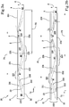
- the truss structure 23 is part of a web 233 which comprises, in addition to the truss structure 23, an inner rib 234 and an outer rib 235.
- the inner rib 234 and the outer rib 235 are preferably continuous, in order to simplify joining with the crosspieces 21 and 22.
- the whole web 233 like the truss structure 23, extends mainly in the plane T.
- openings 236 and 237 are included between the rods 230.
- the web 233 is obtained starting from a flat laminate, inside which, by removal of material, the openings 236 and 237 adjacent to one another are obtained.
- the portions of material that remain between two openings 236 and 237 adjacent to each other constitute the rods 230 of the truss structure 23.
- the removal of material to form openings 236 and 237 can be advantageously performed by laser cutting. This technology allows a wide freedom in the choice of the shape of the openings 236 and 237 and, consequently, of the shape of the rods 230. Alternatively, the removal of material to form openings 236 and 237 can be performed by other technologies known by the skilled person.
- a first flat laminate is worked to obtain the truss structure 23 and the two ribs 234 and 235.
- a second laminate also preferably flat, is joined to the outer rib 235, so as to form the first crosspiece 21.
- the elongated structure 20 is designed to support two panels 19, one for each side, the web 233 and the first crosspiece 21 can be joined so as to form as a whole a structure with a T-shaped cross-section (see, for example, figure 5.a ).
- the elongated structure 20 is designed to support a single panel 19, the web 233 and the first crosspiece 21 can be joined so as to form as a whole a structure with an L-shaped cross-section.
- the union between the web 233 and the first crosspiece 21 is preferably obtained by welding, even more preferably by laser welding.
- the first crosspiece 21, in addition to the first abutment surface 211, also defines an external finishing surface 210, which potentially remains visible next to the panel 19.
- the union between the web 233 and the first crosspiece 21 by welding has the advantage of obtaining that the outer finishing surface 210 is defined by two identical corners and which can potentially be sharp corners (see for example figure 4.b ).
- the union between the web 233 and the first crosspiece 21 can be obtained by bolting (not shown in the attached figures).
- the thickness t of the web 233 must be such as to allow the holes which receive the bolt stems to be formed therein.
- a single flat laminate can be machined by removing material, so as to form the truss structure 23 and then folded so as to form the first crosspiece 21 as well.
- the web 233 and the first crosspiece 21 necessarily form a structure with an L-shaped cross-section, designed to support a single panel 19 (see, for example, figure 4.a ).
- This embodiment has the advantage of replacing the welding step with a simpler profile bending step.
- a single profile with an L-shaped cross-section can be machined by removing material, so as to simultaneously form the truss structure 23 on a wing and the first crosspiece 21 on the other wing.
- the elongated structure 20 is designed to support a single panel 19. This embodiment (not shown) has the advantage of completely avoiding both the welding step and the profile bending step.
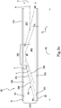
- Figure 5.b shows another solution, alternative to that of figure 5.a , to support two panels 19, one for each side of the elongated structure 20.
- two elongated structures 20 with an L-shaped cross-section are brought together.
- the elongated structure 20 shown on the right is identical to that of figure 4.b , while the one represented on the left is symmetrical with respect to a plane parallel to plane T.
- a seal 30 is also included.
- the seal 30 extends between the two webs 233, parallel to the plane T, so as to cover laterally the openings 236 and 237 which are located between the rods 230 of the truss structure 23.
- a similar side cover of the openings 236 and 237 is obtained by the edges of panels 19.
- the truss structure 23 by cutting the rods 230 from a flat metal laminate and welding them one by one directly to the first crosspiece 21 and to the second crosspiece 22.
- the rods 230 define their own longitudinal axis x.
- the minimum cross section s is usually considered perpendicular to the x axis.
- the web 233 extends into the plane T well beyond the distance d .
- the web 233 extends from the outside to the inside well beyond the thickness of the panel 19. This makes it possible to apply to the web 233 a profile 221 with an L-shaped cross section and adapted to define the second crosspiece 22.
- the second crosspiece 22 can be applied to the web 233 subsequently to the other steps of making the elongated structure 20, even more preferably it can be applied in a removable manner.
- the second crosspiece 22 can be applied to the web 233 by one or more fasteners 224, for example bolts.
- spacers 32 are interposed between the abutment surfaces 211 and 222 and the panel 19.
- a first spacer 32 is arranged between the outer surface of the panel 19 and the first abutment surface 211 of the window frame 200.
- a second spacer 32 is preferably provided between the inner surface of the panel 19 and the second abutment surface 222 of the window frame 200.
- the spacers 32 are designed to prevent direct contact between the metal of the abutment surfaces 211 and 222 and the panel 19, especially when the latter is made of glass.
- the thickness of the spacers 32 is usually between 2.5 mm and 6 mm, preferably equal to 5 mm. This thickness causes the distance d between the abutment surfaces 211 and 222 of the window frame 200 to be greater than the thickness of the panel 19 which is usually between 20 mm and 70 mm.
- each spacer 32 can also be flanked by a sealing cord 33, for example made of silicone.
- part of the technical features of the elongated structure 20 are expressed through some parameters: the distance d between the abutment surfaces 211 and 222; the length of the shortest between the outer edge 231 and the inner edge 232 of each rod 230; the pitches p1 and p2 between the connection zones 213 and 223 of the crosspieces 21 and 22; and the extension s of the minimum cross section of each rod 230.
- These parameters were defined by the applicant through a series of experimental investigations and numerical simulations, aimed at studying the behaviour of the elongated structure 20 from a structural and a thermal point of view.
- the measurement of the parameters considered here can be obtained in a rather intuitive way.
- the openings 236 and 237 have a triangular shape in the proper sense and therefore it is intuitive to consider the vertices of the triangles as ends of the edges.
- the length of the outer edge 231 and the inner edge 232 of each rod 230 can easily be measured from the vertices representing the ends.
- pitches p1 and p2 they can be measured between the midpoints M1 and M2 of the respective connection zones 213 and 223 of the crosspieces 21 and 22.
- the pitches p1 and p2 are usually identical.
- the midpoint of a connection zone coincides with the vertex of the corresponding aperture.
- the midpoint M1 of the connection zone 213 coincides with the vertex of the opening 236, while the midpoint M2 of the connection zone 223 coincides with the vertex of the opening 237.
- each edge has an end defined by the midpoint of a crosspiece connection zone.
- the inner end of the outer edge 231 is the midpoint M2 of the connection zone 223.
- the outer end of the inner edge 232 is the midpoint M1 of the connection zone 213.
- the simulations performed by the applicant have assumed a condition that can be defined as winter, in which the inner part of the window frame is exposed to a temperature of 20°C and the external part is exposed to a temperature of 0°C. It is of course possible to assume different conditions, for example summer, but the results of the simulation would not change.
- ⁇ T i.e. the maximum measurable temperature difference between the inside and the outside of the elongated structure 20. It is considered that an acceptable ⁇ T in these conditions must be at least 15.5°C. ⁇ Ts lower than 15.5 ° C indicate excessive heat transmission from the inside to the outside, a situation wherein the heat itself is dispersed in the external environment, reducing comfort inside.
- All the various configurations considered below for the elongated structure 20 are made starting from a flat steel laminate having a thickness t of 5 mm, measured in a direction k .
- a window frame comprising a continuous web, without any truss structure, is understandably free of any thermal break.
- the thermal bridge between the inside and the outside is far too large and, consequently, ⁇ T is excessively low.
- a first configuration for which the results of the simulation are reported here is that of figure 9 .
- the openings 236 extend for 410 mm in the direction i and for 30 mm in the direction j.
- the measurement of 30 mm in the direction j is dictated by the need to maintain the openings 236 included in the typical thickness of a panel 19.
- the pitches p1 and p2 between the connection zones 213 and 223 of the crosspieces 21 and 22 coincide and are equal to 420 mm (in the direction i ).
- the structural and thermal continuity between inside and outside is guaranteed by some short rods 230, substantially perpendicular to the plane TT of the abutment surfaces 211 and 222 (also identifiable as the plane ik ) .
- the rods are 30 mm long (in the direction j ) and have a constant width of 10 mm (in the direction i ). Consequently, the minimum cross section of the rod 230 has an extension s equal to 2 t .
- the simulated ⁇ T is 12.297°C, and is therefore excessively low.
- a second configuration for which the results of the simulation are reported here is that of figure 10 .
- the basic idea of the thermal break of figure 9 has been exasperated.
- the performances of the configuration of figure 9 although insufficient, have suggested that the use of openings 236 may be useful, but that at the same time the distance of 30 mm in direction j is excessively short.
- hypothesized herein are 415 mm-long (in direction i ) and 105 mm-wide (in direction j ) openings 236.
- the result is that the structural and thermal continuity between inside and outside is guaranteed by some rods 230, substantially perpendicular to the plane TT of the abutment surfaces.
- the rods are 105 mm long (in direction j ) and have a constant width of 5 mm (in direction i ). Consequently, the minimum cross section of the rod 230 has an extension s equal to t. Pitches p1 and p2 are still identical and equal to 420 mm. For this configuration the simulated ⁇ T is 16.636°C, and is therefore excellent. Naturally, such a configuration cannot have any practical confirmation, for at least two reasons, both immediately understandable by the skilled person. First of all, it is not possible for a panel 19 to cover with its own thickness a length of 105 mm in the direction j and this nullifies some of the hypotheses made at the beginning for the simulation. The consequence would be that the openings 236 and the cold parts of the window frame would enter markedly inside the building. In addition, the rods 230, 105 mm long and 5 mm wide, are far too thin to guarantee the necessary structural features.
- a third configuration for which the results of the simulation are reported herein is that of figure 11 .
- the thermal break of figure 10 that is the long and thin rods 230, within a thickness of 30 mm, like that of figure 9 .
- the solution explored here has been to incline the rods 230 each of which now has its own x axis. Because of their inclination, the rods 230 have here an outer edge 231 and an inner edge 232, having different lengths.
- the connection zones of the crosspieces are defined.
- the extension s of the minimum cross section is equal to t (5 mm) and the shorter edge of the rod 230 (i.e. the outer one) is 83 mm long.
- the pitch p2 between the connection zones 223 of the crosspiece 22 has been reduced to 210 mm (in direction i ).
- the simulated ⁇ T is 13.386°C, and is therefore too low, but some insights seem to be promising, in particular that of tilting the rods 230.
- a fourth configuration for which the results of the simulation are reported herein is that of figure 12 and directly derives from that of figure 11 .
- the rods 230 are more inclined, so as to be longer while remaining within the thickness of 30 mm measured in the direction j .
- the extension s of the minimum cross section is equal to 2t (10 mm) and its shorter edge of the rod 230 (i.e. the outer one) is 120 mm long.
- the pitch p2 has been increased to 420 mm (in direction i ).
- the simulated ⁇ T is of 15.507°C, and is therefore acceptable, but it is assumed that some further improvement can be achieved.
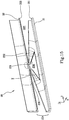
- a fifth configuration for which the results of the simulation are reported herein is that of figure 13 and directly derives from that of figure 12 .
- the rods 230 are tapered, so that the extension s of the minimum cross section is reduced to t (5 mm).
- Another effect of the tapering is that the shorter edge of the rod 230 (i.e. the outer one) is slightly longer: 124 mm.
- the pitch p2 was kept at 420 mm (in direction i ).
- the simulated ⁇ T is 16.588°C, and is therefore excellent.
- the tapering of the rods 230 does not imply a significant deterioration of the structural features. Therefore, this configuration is considered optimal. Despite this, it is considered appropriate to try some further configuration.
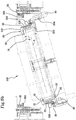
- a sixth configuration for which the simulation results are reported here is that of figure 14 , and derives directly from that of figure 13 .
- the rods 230 are tapered, so that the extension s of the minimum cross section is kept equal to t (5 mm) and so that the opposite end of the single rod is decidedly wider to investigate the possibility to improve the mechanical features.
- the tapering thus accentuated causes the shorter edge of the rod 230 (i.e. the outer one) to be considerably shortened: 72 mm.
- the pitch between the connection zones of the crosspieces was maintained at 420 mm (in direction i ).
- the simulated ⁇ T drops to 14.255°C, and is therefore excessively low.
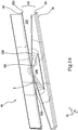
- a seventh configuration for which the simulation results are reported here is that of figure 15 , and derives directly from that of figure 14 .
- the rods 230 are strongly tapered, and essentially have the same shape as those of figure 14 .
- the difference between the two solutions is the development of the shorter edge of the rod 230 (i.e. the outer one).
- the outer edge 231 of the rod 230 is rectilinear and therefore has a development equal to the geometric length: 72 mm.
- the outer edge 231 of the rod 230 is undulated and therefore has a decidedly greater development than the geometric length: 124 mm.
- an eighth configuration for which the simulation results are reported here is that of figure 16 , and derives directly from that of figure 13 .
- the configuration of figure 13 is maintained unchanged, except for the addition of a strut 238 which extends in a direction j from the outer side towards the inner side of the elongated structure 20, but remains disconnected by a few tenths of a millimetre.
- the presence of the strut 238 is advantageous from a structural point of view.
- one of the most severe design conditions is that in which the wind applies a pressure perpendicular to the surface of the panel 19.
- the strut 238 comes into contact with the inner rib 234, from which it is separated by a few tenths of a millimetre. In this condition, therefore, the strut 238 works by compression, actively cooperating in transferring the wind load. Furthermore, in accordance with the configuration of figure 16 , the strut comprises an assembly hole which allows structurally connecting the window frame 20 to a side structure. For this configuration the simulated ⁇ T is maintained at 16.261 °C, and is therefore optimal.
- the invention also relates to a window frame 200 comprising a plurality of elongated structures 20 in accordance with the above description.
- the elongated structures 20 are joined together so as to constitute the sides of a polygon, usually but not necessarily a rectangle.
- the elongated structures 20 are arranged so that the respective first abutment surfaces 211, defined by each of the respective first crosspieces 21, lie on the same plane.
- the elongated structures 20 are preferably arranged so that the respective second abutment surfaces 222, defined by the respective second crosspieces 22, lie on the same plane.
- the invention relates to a window 219 comprising a window frame 200 in accordance with what is described above and a panel 19.
- the panel 19 extends mainly in the plane TT parallel to the abutment surfaces 211 and 222.
- the panel 19 is made in such a way as to have a low thermal conductivity.
- the panel 19 can comprise an athermal glass and/or insulating glasses.
- the panel 19 can be made with different materials or techniques.
- the fact that the second crosspiece 22 can be applied to the window frame 20 in a removable manner, for example by means of bolts 224, allows a high flexibility in fitting the window 219.
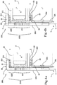
- Figures 6 to 8 represent a particular solution according to the invention, in which at least one openable window frame 200 is arranged.
- FIG. 6 On the right there is a fixed structure, on which a window frame 200 according to the invention is hinged.
- the fixed structure is in turn an elongated structure 20 according to the invention, but this is not at all necessary and the fixed structure could be a wall, a frame or any other element of the construction.
- a window frame 200 according to the invention is therefore mounted on the fixed structure by at least one hinge 40.
- Figure 7 shows the opposite end of the same openable window frame in figure 6 .
- a window frame 200 according to the invention on the left there is a fixed structure, on which a window frame 200 according to the invention abuts when it is closed.
- the fixed structure is an elongated structure 20 according to the invention, but as already stated above this is not necessary.
- the window frame 200 according to the invention comprises locking means 42, known per se, for locking it in the closed position on the fixed structure.
- the locking means 42 can for example be controlled by a handle and/or a key and can comprise a bolt, a lock, a latch or the like.
- a chamber 44 is generated between the elongated structure 20 and the fixed structure.
- a chamber 44 it is possible to appropriately shape the cross-section of the fixed structure, or the cross-section of the elongated structure 20 of the openable window frame 200 or both cross-sections.
- the elongated structure 20 of the openable window frame 200 comprises a seal 30 which laterally covers the openings 236 and 237.
- the openings 236 and 237 are covered by the edge of the panel 19.
- the seal 30 arranged on the movable window frame also includes a lip 300 suitable for cooperating with a lip 302 arranged on a corresponding seal arranged on the fixed structure.
- the purpose, the structure and the operation of the lip 300 and of the lip 302 are known. Briefly, by bringing the window frame 200 to the closed position, at least one of the two lips is deformed and/or compressed so as to seal the closure and avoid leakage of air between inside and outside.
- the particularity of the lips shown in figures 6 and 7 is that they are included in seals 30 also intended to cover laterally the openings 236 and 237 of the respective elongated structures 20.
- the invention allows to overcome the drawbacks highlighted above with reference to the known art.
- the present invention offers a window frame structure which has at the same time a reduced cross-section, excellent thermal insulation features and the mechanical features necessary to withstand the design loads.
- the present invention makes available a window frame and a window made with the window frame structure having the above-described features. It is clear that the specific features are described in relation to various embodiments of the invention with exemplifying and non-limiting intent. Obviously, a person skilled in the art may make further modifications and variations to this invention, in order to meet contingent and specific requirements. For example, the technical features described in connection with an embodiment of the invention may be extrapolated from it and applied to other embodiments of the invention. Such modifications and variations are, however, contained within the scope of the invention, as defined by the following claims.
Landscapes
- Engineering & Computer Science (AREA)
- Civil Engineering (AREA)
- Structural Engineering (AREA)
- Wing Frames And Configurations (AREA)
Claims (16)
- Längliche Struktur (20) für einen Fensterrahmen (200), der zum Tragen einer Platte (19) zum Trennen einer inneren Umgebung von einer äußeren Umgebung geeignet ist, wobei die längliche Struktur (20) umfasst:- ein erstes Querstück (21), das eine erste Widerlagerfläche (211) definiert;- ein zweites Querstück (22), das eine zweite Widerlagerfläche (222) parallel zur ersten Widerlagerfläche (211) definiert;- eine Gitterträgerstruktur (23), die das erste Querstück (21) und das zweite Querstück (22) verbindet; wobei die Gitterträgerstruktur (23) Stangen (230) umfasst, die sich von Verbindungszonen (213) des ersten Querstücks (21) zu Verbindungszonen (223) des zweiten Querstücks (22) erstrecken;dadurch gekennzeichnet, dass die Stangen (230) verjüngt sind.
- Längliche Struktur (20) nach Anspruch 1, wobei die erste Widerlagerfläche (211) um einen Abstand d von der zweiten Widerlagerfläche (222) beabstandet ist und wobei der Abstand d zwischen 25 mm und 82 mm liegt.
- Längliche Struktur (20) nach Anspruch 1 oder 2, wobei eine jede Stange (230) eine Außenkante (231), die dem ersten Querstück (21) zugewandt ist, und eine Innenkante (232), die dem zweiten Querstück (22) zugewandt ist, umfasst, und wobei in einer jeden Stange (230) die am kürzesten zwischen der Außenkante (231) und der Innenkante (232) mindestens 100 mm lang ist.
- Längliche Struktur (20) nach einem der vorhergehenden Ansprüche, wobei:- die Verbindungszonen (213) des ersten Querstücks (21) um einen Abstand p1 voneinander beabstandet sind;- die Verbindungszonen (223) des zweiten Querstücks (22) um einen Abstand p2 voneinander beabstandet sind;und wobei mindestens eines unter p1 und p2 größer als 350 mm ist.
- Längliche Struktur (20) nach einem der vorhergehenden Ansprüche, wobei eine jede Stange (230) einen minimalen Querschnitt mit einer Erstreckung s definiert, so dass t ≤ s ≤ 2t ist, wobei t die Dicke der Gitterträgerstruktur (23) ist.
- Längliche Struktur (20) nach einem der vorhergehenden Ansprüche, wobei sich die erste Widerlagerfläche (211), die durch das erste Querstück (21) definiert ist, und die zweite Widerlagerfläche (222), die durch das zweite Querstück (22) definiert ist, parallel zu einer Ebene TT erstrecken, und wobei sich die Gitterträgerstruktur (23) hauptsächlich in einer Ebene T, senkrecht zur Ebene TT erstreckt.
- Längliche Struktur (20) nach einem der vorhergehenden Ansprüche, wobei die Gitterträgerstruktur (23) Teil eines Stegs (233) ist, der ferner eine innere Rippe (234) und eine äußere Rippe (235) umfasst.
- Längliche Struktur (20) nach einem der vorhergehenden Ansprüche, hergestellt aus einem metallischen Material, vorzugsweise ausgewählt in der Gruppe bestehend aus Edelstahl, Eisen, Messing, Bronze, Aluminium und Kupfer.
- Längliche Struktur (20) nach einem der vorhergehenden Ansprüche, wobei in der Gitterträgerstruktur (23) Öffnungen (236; 237) zwischen den Stangen (230) enthalten sind.
- Längliche Struktur (20) nach einem der Ansprüche 6 bis 9, wobei t senkrecht zur Ebene T gemessen wird und zwischen 3 mm und 7 mm, vorzugsweise zwischen 4 mm und 6 mm liegt.
- Längliche Struktur (20) nach einem der vorhergehenden Ansprüche, wobei das zweite Querstück (22) auf entfernbare Weise auf die längliche Struktur (20) aufgebracht wird.
- Längliche Struktur (20) nach einem der vorhergehenden Ansprüche, wobei der Steg (233) ferner eine Strebe (238) umfasst, die von der äußeren Rippe (235) zur inneren Rippe (234) vorsteht oder umgekehrt, wobei sie um einen Zehntel Millimeter von der Rippe entfernt, in die sie hineinragt, beabstandet bleibt.
- Längliche Struktur (20) nach dem vorhergehenden Anspruch, wobei die Strebe (238) ein Montageloch umfasst.
- Fensterrahmen (200), umfassend eine Vielzahl an länglichen Strukturen (20) nach einem der vorhergehenden Ansprüche.
- Fensterrahmen (200) nach dem vorhergehenden Anspruch, wobei mindestens eine längliche Struktur (20) eine Dichtung (30) umfasst, die die Öffnungen (236; 237) seitlich abdeckt, um die in ihnen ruhende Luft von außen isoliert zu behalten.
- Fenster (219), umfassend einen Fensterrahmen (200) nach Anspruch 14 oder 15 und eine Platte (19), die sich hauptsächlich in der Ebene TT erstreckt.
Applications Claiming Priority (2)
| Application Number | Priority Date | Filing Date | Title |
|---|---|---|---|
| IT102017000053783A IT201700053783A1 (it) | 2017-05-18 | 2017-05-18 | Serramento con struttura a traliccio |
| PCT/IB2018/053148 WO2018211353A1 (en) | 2017-05-18 | 2018-05-07 | Window frame with a truss structure |
Publications (2)
| Publication Number | Publication Date |
|---|---|
| EP3625423A1 EP3625423A1 (de) | 2020-03-25 |
| EP3625423B1 true EP3625423B1 (de) | 2021-06-30 |
Family
ID=59812047
Family Applications (1)
| Application Number | Title | Priority Date | Filing Date |
|---|---|---|---|
| EP18728458.3A Active EP3625423B1 (de) | 2017-05-18 | 2018-05-07 | Fensterrahmen mit einer gitterträgerstruktur |
Country Status (4)
| Country | Link |
|---|---|
| US (1) | US20200087977A1 (de) |
| EP (1) | EP3625423B1 (de) |
| IT (1) | IT201700053783A1 (de) |
| WO (1) | WO2018211353A1 (de) |
Families Citing this family (2)
| Publication number | Priority date | Publication date | Assignee | Title |
|---|---|---|---|---|
| US11248412B2 (en) * | 2019-11-18 | 2022-02-15 | Rehme Custom Doors & Lighting, Inc. | Metallic fenestration systems with improved thermal performance and methods of manufacturing same |
| US20250122760A1 (en) * | 2023-10-16 | 2025-04-17 | Visionar Window Systems Inc. | Window, door or wall frame assembly with thermally insulating truss |
Family Cites Families (5)
| Publication number | Priority date | Publication date | Assignee | Title |
|---|---|---|---|---|
| GB156289A (en) * | 1919-08-11 | 1921-01-13 | Carlo Aiolfi | Improvements in means for holding panes or sheets in position in window frames |
| DK199900556A (da) * | 1999-04-23 | 2000-10-24 | Velux Ind As | Panelsystem |
| PL1510643T3 (pl) * | 2003-09-01 | 2018-06-29 | Forster Profilsysteme Ag | Profil i sposób wytwarzania profilu |
| FR2883624B1 (fr) * | 2005-03-22 | 2008-10-17 | Ent Peraudeau Durbecq Entpr Un | Profil de menuiserie, en particulier pour la realisation d'ouvrants ou de dormants de portes, de fenetres ou de chassis fixes |
| EP1712718A1 (de) * | 2005-04-13 | 2006-10-18 | Forster Rohr- & Profiltechnik AG | Verbundprofil und Verfahren zur Herstellung eines Verbundprofils für Rahmen von Wandelementen, Türen oder Fenstern |
-
2017
- 2017-05-18 IT IT102017000053783A patent/IT201700053783A1/it unknown
-
2018
- 2018-05-07 EP EP18728458.3A patent/EP3625423B1/de active Active
- 2018-05-07 WO PCT/IB2018/053148 patent/WO2018211353A1/en not_active Ceased
- 2018-05-07 US US16/613,938 patent/US20200087977A1/en not_active Abandoned
Non-Patent Citations (1)
| Title |
|---|
| None * |
Also Published As
| Publication number | Publication date |
|---|---|
| IT201700053783A1 (it) | 2018-11-18 |
| US20200087977A1 (en) | 2020-03-19 |
| EP3625423A1 (de) | 2020-03-25 |
| WO2018211353A1 (en) | 2018-11-22 |
Similar Documents
| Publication | Publication Date | Title |
|---|---|---|
| US12012800B2 (en) | Aperture cover with overlapping VIG unit and connection profile connected to structural frame member | |
| EP3447229B1 (de) | Zwischenstück zur wärmekompensation | |
| EP3625423B1 (de) | Fensterrahmen mit einer gitterträgerstruktur | |
| KR20200132063A (ko) | 보조레일용 여밈대 풍지구조를 가지는 미서기창호 | |
| EP0733765A1 (de) | Verbundprofile und ihr Zusammenbau für hochisolierte und holzverkleidete Tür- und Fensterrahmen | |
| CN221590777U (zh) | 被动式多腔体静音防寒门窗 | |
| CN215166931U (zh) | 一种单元体幕墙结构 | |
| CN216894133U (zh) | 具有玻纤聚氨酯加强芯的窗型材及节能耐火断桥铝合金窗 | |
| US11933100B2 (en) | Metallic fenestration systems with improved thermal performance and methods of manufacturing same | |
| CN211144177U (zh) | 一种基于铝木结构的新型门窗 | |
| GB2405172A (en) | Frame with intumescent material | |
| CN220645756U (zh) | 一种高密封性的平开窗 | |
| CN203129846U (zh) | 新型框扇平齐式隔热窗 | |
| CN206035221U (zh) | 一种自增强门窗结构 | |
| CN210564240U (zh) | 一种连接伸缩缝门窗型材 | |
| CN212129590U (zh) | 一种改进型装配式建筑预制混凝土板的板缝胶条防水装置 | |
| CN222835623U (zh) | 一种适配于窗纱一体断桥窗的转角结构 | |
| CN221144059U (zh) | 一种极窄平开门窗结构 | |
| RU239949U1 (ru) | Дверной блок с терморазрывом | |
| CN222457281U (zh) | 一种断桥多轨下框排水结构及推拉门窗 | |
| CN224093302U (zh) | 一种具有良好隔音性能的铝合金平开窗 | |
| CN221942310U (zh) | 一种断桥铝系统窗的窗框密封结构 | |
| CN218758136U (zh) | 一种气密型双层幕墙 | |
| CN222501459U (zh) | 一种门窗用隔热铝型材 | |
| JP2002242542A (ja) | サッシ窓の製造方法 |
Legal Events
| Date | Code | Title | Description |
|---|---|---|---|
| STAA | Information on the status of an ep patent application or granted ep patent |
Free format text: STATUS: UNKNOWN |
|
| STAA | Information on the status of an ep patent application or granted ep patent |
Free format text: STATUS: THE INTERNATIONAL PUBLICATION HAS BEEN MADE |
|
| PUAI | Public reference made under article 153(3) epc to a published international application that has entered the european phase |
Free format text: ORIGINAL CODE: 0009012 |
|
| STAA | Information on the status of an ep patent application or granted ep patent |
Free format text: STATUS: REQUEST FOR EXAMINATION WAS MADE |
|
| 17P | Request for examination filed |
Effective date: 20191112 |
|
| AK | Designated contracting states |
Kind code of ref document: A1 Designated state(s): AL AT BE BG CH CY CZ DE DK EE ES FI FR GB GR HR HU IE IS IT LI LT LU LV MC MK MT NL NO PL PT RO RS SE SI SK SM TR |
|
| AX | Request for extension of the european patent |
Extension state: BA ME |
|
| DAV | Request for validation of the european patent (deleted) | ||
| DAX | Request for extension of the european patent (deleted) | ||
| GRAP | Despatch of communication of intention to grant a patent |
Free format text: ORIGINAL CODE: EPIDOSNIGR1 |
|
| STAA | Information on the status of an ep patent application or granted ep patent |
Free format text: STATUS: GRANT OF PATENT IS INTENDED |
|
| INTG | Intention to grant announced |
Effective date: 20210114 |
|
| GRAS | Grant fee paid |
Free format text: ORIGINAL CODE: EPIDOSNIGR3 |
|
| GRAA | (expected) grant |
Free format text: ORIGINAL CODE: 0009210 |
|
| STAA | Information on the status of an ep patent application or granted ep patent |
Free format text: STATUS: THE PATENT HAS BEEN GRANTED |
|
| AK | Designated contracting states |
Kind code of ref document: B1 Designated state(s): AL AT BE BG CH CY CZ DE DK EE ES FI FR GB GR HR HU IE IS IT LI LT LU LV MC MK MT NL NO PL PT RO RS SE SI SK SM TR |
|
| REG | Reference to a national code |
Ref country code: CH Ref legal event code: EP |
|
| REG | Reference to a national code |
Ref country code: AT Ref legal event code: REF Ref document number: 1406483 Country of ref document: AT Kind code of ref document: T Effective date: 20210715 |
|
| REG | Reference to a national code |
Ref country code: DE Ref legal event code: R096 Ref document number: 602018019382 Country of ref document: DE |
|
| REG | Reference to a national code |
Ref country code: IE Ref legal event code: FG4D |
|
| REG | Reference to a national code |
Ref country code: LT Ref legal event code: MG9D |
|
| PG25 | Lapsed in a contracting state [announced via postgrant information from national office to epo] |
Ref country code: HR Free format text: LAPSE BECAUSE OF FAILURE TO SUBMIT A TRANSLATION OF THE DESCRIPTION OR TO PAY THE FEE WITHIN THE PRESCRIBED TIME-LIMIT Effective date: 20210630 Ref country code: FI Free format text: LAPSE BECAUSE OF FAILURE TO SUBMIT A TRANSLATION OF THE DESCRIPTION OR TO PAY THE FEE WITHIN THE PRESCRIBED TIME-LIMIT Effective date: 20210630 Ref country code: BG Free format text: LAPSE BECAUSE OF FAILURE TO SUBMIT A TRANSLATION OF THE DESCRIPTION OR TO PAY THE FEE WITHIN THE PRESCRIBED TIME-LIMIT Effective date: 20210930 |
|
| REG | Reference to a national code |
Ref country code: NL Ref legal event code: MP Effective date: 20210630 |
|
| REG | Reference to a national code |
Ref country code: AT Ref legal event code: MK05 Ref document number: 1406483 Country of ref document: AT Kind code of ref document: T Effective date: 20210630 |
|
| PG25 | Lapsed in a contracting state [announced via postgrant information from national office to epo] |
Ref country code: GR Free format text: LAPSE BECAUSE OF FAILURE TO SUBMIT A TRANSLATION OF THE DESCRIPTION OR TO PAY THE FEE WITHIN THE PRESCRIBED TIME-LIMIT Effective date: 20211001 Ref country code: SE Free format text: LAPSE BECAUSE OF FAILURE TO SUBMIT A TRANSLATION OF THE DESCRIPTION OR TO PAY THE FEE WITHIN THE PRESCRIBED TIME-LIMIT Effective date: 20210630 Ref country code: RS Free format text: LAPSE BECAUSE OF FAILURE TO SUBMIT A TRANSLATION OF THE DESCRIPTION OR TO PAY THE FEE WITHIN THE PRESCRIBED TIME-LIMIT Effective date: 20210630 Ref country code: LV Free format text: LAPSE BECAUSE OF FAILURE TO SUBMIT A TRANSLATION OF THE DESCRIPTION OR TO PAY THE FEE WITHIN THE PRESCRIBED TIME-LIMIT Effective date: 20210630 Ref country code: NO Free format text: LAPSE BECAUSE OF FAILURE TO SUBMIT A TRANSLATION OF THE DESCRIPTION OR TO PAY THE FEE WITHIN THE PRESCRIBED TIME-LIMIT Effective date: 20210930 |
|
| PG25 | Lapsed in a contracting state [announced via postgrant information from national office to epo] |
Ref country code: SK Free format text: LAPSE BECAUSE OF FAILURE TO SUBMIT A TRANSLATION OF THE DESCRIPTION OR TO PAY THE FEE WITHIN THE PRESCRIBED TIME-LIMIT Effective date: 20210630 Ref country code: EE Free format text: LAPSE BECAUSE OF FAILURE TO SUBMIT A TRANSLATION OF THE DESCRIPTION OR TO PAY THE FEE WITHIN THE PRESCRIBED TIME-LIMIT Effective date: 20210630 Ref country code: ES Free format text: LAPSE BECAUSE OF FAILURE TO SUBMIT A TRANSLATION OF THE DESCRIPTION OR TO PAY THE FEE WITHIN THE PRESCRIBED TIME-LIMIT Effective date: 20210630 Ref country code: RO Free format text: LAPSE BECAUSE OF FAILURE TO SUBMIT A TRANSLATION OF THE DESCRIPTION OR TO PAY THE FEE WITHIN THE PRESCRIBED TIME-LIMIT Effective date: 20210630 Ref country code: PT Free format text: LAPSE BECAUSE OF FAILURE TO SUBMIT A TRANSLATION OF THE DESCRIPTION OR TO PAY THE FEE WITHIN THE PRESCRIBED TIME-LIMIT Effective date: 20211102 Ref country code: NL Free format text: LAPSE BECAUSE OF FAILURE TO SUBMIT A TRANSLATION OF THE DESCRIPTION OR TO PAY THE FEE WITHIN THE PRESCRIBED TIME-LIMIT Effective date: 20210630 Ref country code: SM Free format text: LAPSE BECAUSE OF FAILURE TO SUBMIT A TRANSLATION OF THE DESCRIPTION OR TO PAY THE FEE WITHIN THE PRESCRIBED TIME-LIMIT Effective date: 20210630 Ref country code: CZ Free format text: LAPSE BECAUSE OF FAILURE TO SUBMIT A TRANSLATION OF THE DESCRIPTION OR TO PAY THE FEE WITHIN THE PRESCRIBED TIME-LIMIT Effective date: 20210630 Ref country code: AT Free format text: LAPSE BECAUSE OF FAILURE TO SUBMIT A TRANSLATION OF THE DESCRIPTION OR TO PAY THE FEE WITHIN THE PRESCRIBED TIME-LIMIT Effective date: 20210630 |
|
| PG25 | Lapsed in a contracting state [announced via postgrant information from national office to epo] |
Ref country code: PL Free format text: LAPSE BECAUSE OF FAILURE TO SUBMIT A TRANSLATION OF THE DESCRIPTION OR TO PAY THE FEE WITHIN THE PRESCRIBED TIME-LIMIT Effective date: 20210630 |
|
| REG | Reference to a national code |
Ref country code: DE Ref legal event code: R097 Ref document number: 602018019382 Country of ref document: DE |
|
| PG25 | Lapsed in a contracting state [announced via postgrant information from national office to epo] |
Ref country code: DK Free format text: LAPSE BECAUSE OF FAILURE TO SUBMIT A TRANSLATION OF THE DESCRIPTION OR TO PAY THE FEE WITHIN THE PRESCRIBED TIME-LIMIT Effective date: 20210630 |
|
| PLBE | No opposition filed within time limit |
Free format text: ORIGINAL CODE: 0009261 |
|
| STAA | Information on the status of an ep patent application or granted ep patent |
Free format text: STATUS: NO OPPOSITION FILED WITHIN TIME LIMIT |
|
| PG25 | Lapsed in a contracting state [announced via postgrant information from national office to epo] |
Ref country code: AL Free format text: LAPSE BECAUSE OF FAILURE TO SUBMIT A TRANSLATION OF THE DESCRIPTION OR TO PAY THE FEE WITHIN THE PRESCRIBED TIME-LIMIT Effective date: 20210630 |
|
| 26N | No opposition filed |
Effective date: 20220331 |
|
| PG25 | Lapsed in a contracting state [announced via postgrant information from national office to epo] |
Ref country code: IT Free format text: LAPSE BECAUSE OF FAILURE TO SUBMIT A TRANSLATION OF THE DESCRIPTION OR TO PAY THE FEE WITHIN THE PRESCRIBED TIME-LIMIT Effective date: 20210630 |
|
| REG | Reference to a national code |
Ref country code: DE Ref legal event code: R119 Ref document number: 602018019382 Country of ref document: DE |
|
| REG | Reference to a national code |
Ref country code: CH Ref legal event code: PL |
|
| REG | Reference to a national code |
Ref country code: BE Ref legal event code: MM Effective date: 20220531 |
|
| GBPC | Gb: european patent ceased through non-payment of renewal fee |
Effective date: 20220507 |
|
| PG25 | Lapsed in a contracting state [announced via postgrant information from national office to epo] |
Ref country code: MC Free format text: LAPSE BECAUSE OF FAILURE TO SUBMIT A TRANSLATION OF THE DESCRIPTION OR TO PAY THE FEE WITHIN THE PRESCRIBED TIME-LIMIT Effective date: 20210630 Ref country code: LU Free format text: LAPSE BECAUSE OF NON-PAYMENT OF DUE FEES Effective date: 20220507 Ref country code: LI Free format text: LAPSE BECAUSE OF NON-PAYMENT OF DUE FEES Effective date: 20220531 Ref country code: CH Free format text: LAPSE BECAUSE OF NON-PAYMENT OF DUE FEES Effective date: 20220531 |
|
| PG25 | Lapsed in a contracting state [announced via postgrant information from national office to epo] |
Ref country code: LT Free format text: LAPSE BECAUSE OF FAILURE TO SUBMIT A TRANSLATION OF THE DESCRIPTION OR TO PAY THE FEE WITHIN THE PRESCRIBED TIME-LIMIT Effective date: 20210630 Ref country code: IE Free format text: LAPSE BECAUSE OF NON-PAYMENT OF DUE FEES Effective date: 20220507 Ref country code: FR Free format text: LAPSE BECAUSE OF NON-PAYMENT OF DUE FEES Effective date: 20220531 |
|
| PG25 | Lapsed in a contracting state [announced via postgrant information from national office to epo] |
Ref country code: GB Free format text: LAPSE BECAUSE OF NON-PAYMENT OF DUE FEES Effective date: 20220507 Ref country code: DE Free format text: LAPSE BECAUSE OF NON-PAYMENT OF DUE FEES Effective date: 20221201 Ref country code: BE Free format text: LAPSE BECAUSE OF NON-PAYMENT OF DUE FEES Effective date: 20220531 |
|
| PG25 | Lapsed in a contracting state [announced via postgrant information from national office to epo] |
Ref country code: MK Free format text: LAPSE BECAUSE OF FAILURE TO SUBMIT A TRANSLATION OF THE DESCRIPTION OR TO PAY THE FEE WITHIN THE PRESCRIBED TIME-LIMIT Effective date: 20210630 Ref country code: CY Free format text: LAPSE BECAUSE OF FAILURE TO SUBMIT A TRANSLATION OF THE DESCRIPTION OR TO PAY THE FEE WITHIN THE PRESCRIBED TIME-LIMIT Effective date: 20210630 |
|
| PG25 | Lapsed in a contracting state [announced via postgrant information from national office to epo] |
Ref country code: HU Free format text: LAPSE BECAUSE OF FAILURE TO SUBMIT A TRANSLATION OF THE DESCRIPTION OR TO PAY THE FEE WITHIN THE PRESCRIBED TIME-LIMIT; INVALID AB INITIO Effective date: 20180507 |
|
| PG25 | Lapsed in a contracting state [announced via postgrant information from national office to epo] |
Ref country code: TR Free format text: LAPSE BECAUSE OF FAILURE TO SUBMIT A TRANSLATION OF THE DESCRIPTION OR TO PAY THE FEE WITHIN THE PRESCRIBED TIME-LIMIT Effective date: 20210630 |
|
| PG25 | Lapsed in a contracting state [announced via postgrant information from national office to epo] |
Ref country code: MT Free format text: LAPSE BECAUSE OF FAILURE TO SUBMIT A TRANSLATION OF THE DESCRIPTION OR TO PAY THE FEE WITHIN THE PRESCRIBED TIME-LIMIT Effective date: 20210630 |