EP3625452B1 - Gerät zur inspektion von windenergieanlagen - Google Patents
Gerät zur inspektion von windenergieanlagen Download PDFInfo
- Publication number
- EP3625452B1 EP3625452B1 EP18723492.7A EP18723492A EP3625452B1 EP 3625452 B1 EP3625452 B1 EP 3625452B1 EP 18723492 A EP18723492 A EP 18723492A EP 3625452 B1 EP3625452 B1 EP 3625452B1
- Authority
- EP
- European Patent Office
- Prior art keywords
- frame structure
- cable
- robot
- rotor blade
- docking
- Prior art date
- Legal status (The legal status is an assumption and is not a legal conclusion. Google has not performed a legal analysis and makes no representation as to the accuracy of the status listed.)
- Active
Links
Images



Classifications
-
- G—PHYSICS
- G01—MEASURING; TESTING
- G01B—MEASURING LENGTH, THICKNESS OR SIMILAR LINEAR DIMENSIONS; MEASURING ANGLES; MEASURING AREAS; MEASURING IRREGULARITIES OF SURFACES OR CONTOURS
- G01B5/00—Measuring arrangements characterised by the use of mechanical techniques
- G01B5/20—Measuring arrangements characterised by the use of mechanical techniques for measuring contours or curvatures
- G01B5/205—Measuring arrangements characterised by the use of mechanical techniques for measuring contours or curvatures of turbine blades or propellers
-
- F—MECHANICAL ENGINEERING; LIGHTING; HEATING; WEAPONS; BLASTING
- F03—MACHINES OR ENGINES FOR LIQUIDS; WIND, SPRING, OR WEIGHT MOTORS; PRODUCING MECHANICAL POWER OR A REACTIVE PROPULSIVE THRUST, NOT OTHERWISE PROVIDED FOR
- F03D—WIND MOTORS
- F03D80/00—Details, components or accessories not provided for in groups F03D1/00 - F03D17/00
- F03D80/50—Maintenance or repair
-
- F—MECHANICAL ENGINEERING; LIGHTING; HEATING; WEAPONS; BLASTING
- F03—MACHINES OR ENGINES FOR LIQUIDS; WIND, SPRING, OR WEIGHT MOTORS; PRODUCING MECHANICAL POWER OR A REACTIVE PROPULSIVE THRUST, NOT OTHERWISE PROVIDED FOR
- F03D—WIND MOTORS
- F03D17/00—Monitoring or testing of wind motors, e.g. diagnostics
-
- F—MECHANICAL ENGINEERING; LIGHTING; HEATING; WEAPONS; BLASTING
- F03—MACHINES OR ENGINES FOR LIQUIDS; WIND, SPRING, OR WEIGHT MOTORS; PRODUCING MECHANICAL POWER OR A REACTIVE PROPULSIVE THRUST, NOT OTHERWISE PROVIDED FOR
- F03D—WIND MOTORS
- F03D80/00—Details, components or accessories not provided for in groups F03D1/00 - F03D17/00
- F03D80/50—Maintenance or repair
- F03D80/55—Cleaning
-
- F—MECHANICAL ENGINEERING; LIGHTING; HEATING; WEAPONS; BLASTING
- F05—INDEXING SCHEMES RELATING TO ENGINES OR PUMPS IN VARIOUS SUBCLASSES OF CLASSES F01-F04
- F05B—INDEXING SCHEME RELATING TO WIND, SPRING, WEIGHT, INERTIA OR LIKE MOTORS, TO MACHINES OR ENGINES FOR LIQUIDS COVERED BY SUBCLASSES F03B, F03D AND F03G
- F05B2260/00—Function
- F05B2260/80—Diagnostics
-
- Y—GENERAL TAGGING OF NEW TECHNOLOGICAL DEVELOPMENTS; GENERAL TAGGING OF CROSS-SECTIONAL TECHNOLOGIES SPANNING OVER SEVERAL SECTIONS OF THE IPC; TECHNICAL SUBJECTS COVERED BY FORMER USPC CROSS-REFERENCE ART COLLECTIONS [XRACs] AND DIGESTS
- Y02—TECHNOLOGIES OR APPLICATIONS FOR MITIGATION OR ADAPTATION AGAINST CLIMATE CHANGE
- Y02E—REDUCTION OF GREENHOUSE GAS [GHG] EMISSIONS, RELATED TO ENERGY GENERATION, TRANSMISSION OR DISTRIBUTION
- Y02E10/00—Energy generation through renewable energy sources
- Y02E10/70—Wind energy
- Y02E10/72—Wind turbines with rotation axis in wind direction
Definitions
- the invention relates to a device for the inspection, cleaning or other examination of objects, for example rotor blades of wind turbines.
- a device in the form of a robot for inspecting rotor blades of wind turbines is known.
- the robot is provided with a plurality of propellers for a flight movement of the robot, via which the height of the robot, for example the frame structure thereof, can be controlled in relation to the ground or the nacelle of the wind turbine.
- the invention allows simple and reliable positional positioning, e.g. vertical positioning of the device, e.g. frame construction or robot or other examination device or cleaning device.
- the invention thus provides an alternative suspension and position control of a device, for example a robot according to WO 2014/059964 A1 , provided via a rope suspension, for example a rope pull-in.
- the device or a device has a frame structure for the examination of a device such as a rotor blade for the inspection, cleaning or maintenance of the same, with a cable pull-in, on which the frame structure is suspended in such a way that it can be adjusted in the vertical direction by moving the cable pull-in, and with one or more Propeller or rotor / s for moving the frame structure in a horizontal direction.
- the frame structure has one, preferably two, or more rotors for horizontal adjustment of the frame structure.
- the device can have a winch that carries the weight of the frame structure or a system via ropes and a pulley, and is connected with ropes for height control and positioning of the frame structure or the system in a y-axis on the blade of a wind turbine.
- Ropes can be connected from the pulley to knots, and, if necessary, two ropes can be run from the knot as a V to the respective corners of the frame structure or the system.
- Ropes can be connected to the frame structure or the system by one node each, and with deflection pulleys, which are present at the four corners of the frame structure or the system for pulling the rope.
- the device can have at least one cable pull-in for moving a cable on or in the frame structure or the system, the cable pull-in in each case containing a linear drive or being formed by a drum winch or cable winch.
- the device can have devices for inspecting and examining the device or a rotor blade of a wind turbine.
- the device can have a robot for inspecting rotor blades of wind turbines.
- the device in particular a robot for inspecting rotor blades of wind turbines, the frame construction having an inner opening surrounding a rotor blade in use, one or more propellers arranged on the frame construction, and a condition detection system attached to the frame construction for preferably non-contact inspection the rotor blades.
- System with a device in particular a robot, according to one of the preceding aspects, preferably with a fixed or mobile installed station, for example a control and evaluation station, and / or a cable for connecting a robot to the station, and / or a cable and / or one or more propellers.
- a fixed or mobile installed station for example a control and evaluation station, and / or a cable for connecting a robot to the station, and / or a cable and / or one or more propellers.
- a cable e.g. a power and / or data cable for connecting the robot to a station, for example on the ground or on a vehicle, in particular a control and evaluation station.
- the damper can be extended telescopically, electrically or hydraulically, a spacer being arranged centrally on a frame or a pair of dampers or spacers being provided at both corners of the frame.
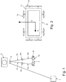
- a winch 1 is provided on the ground or in a transporter or other transport vehicle, so that the system 2 can be moved to the respective place of use.
- the vertical height of the system 2 for example a robot according to FIG WO 2014/059964 A1 , be managed.
- a deflection roller 3 is provided below a nacelle 4 of a wind turbine, wind turbine.
- a blade body for example a rotor blade 5 of the wind energy installation, which the nacelle 4 has, can be examined by means of the system 2.
- a cable pull-in 6 can be provided for height adjustment in or on the system 2, for example the robot.
- the pull-in cable 6 can consist of a linear drive.
- the cable pull-in 6 can also be formed by a drum winch or a cable winch. It is also possible to use these configurations together.
- a pulley 7 can for example according to Fig. 3 be provided on or in the system 2, ie for example the robot 2.
- One or more propellers 9 for positioning in the direction of, for example, in Fig. 2 entered direction x, i.e. in the x-axis direction, allows adjustment of the lateral or horizontal position of the robot.
- One or more further propellers 10 allow the horizontal position of the robot or other examination device 2 to be positioned in the direction of the axis y according to FIG Fig. 2 .
- Corners 11 of the system or of the robot 2 are shown in more detail in FIG Fig. 3 shown.
- a cable 12 of the cable pull-in 6 runs from the winch 1 to the deflection roller 3 and via this on to the robot 2 or the frame structure or other configurations of the device 2.
- the side view Fig. 1 can be one or more nodes 14, see Fig. 1 , be provided in order to connect ropes 13 to ropes 15, the ropes 15 from the node 14 being connected to the system 2 via the pulleys 7 at the four corners 11 of the system 2 up to the rope pull-in 6.
- the cable winch 1 is provided for vertical or horizontal positioning of the device, for example the robot 2. The positioning can take place in the direction of the axis y while maintaining the vertical height of the system 2.
- the cable winch 1 is here on the ground, in a transporter, or in a support frame, which can be stationary or movable in the horizontal direction.
- the cable winch 1 takes over the weight of the system 2 via the cables 12, see for example Fig. 4 .
- the ropes 12 can be connected to the rope 13 via the pulley 3 and via this further to the node or nodes 14. Via the ropes 12, 13, 15 and the cable winch 1, precise height control and positioning of the system 2 is possible in the direction of the y-axis on system 2 or blade 5 of the wind power plant (WEA) controllable.
- WEA wind power plant
- the wind power plant is provided as a cable guide, a cable 12 to be tensioned from the winch 1 via the deflection pulley 3 and this to be connected to the cables 13.
- the ropes 13 each consist of, for example, two ropes that are or are stretched in the form of a V from the deflection roller 3 to the node 14 or connected to them. From the nodes 14, two ropes 15 in the form of a V can be or be connected to the respective corners 11 of the system 2.
- a horizontal position control on the system 2 can take place by means of pulling-in cables.
- the horizontal position control can take place here by means of one or more pull-in cables 6, a linear axis being implemented.
- the ropes 15 of the pull-in cables 6 are connected at all four corners 11 of the system 2, whereby the horizontal position control is ensured.
- the ropes 15 are drawn in or outputted via a pulley by means of a linear axis in or on the frame of the system 2 in order to ensure a horizontal position of the system 2.
- the horizontal position regulation is recorded and controlled by an electronic angle measurement.
- an electronically operating angle measuring device is provided, the measurement results of which are compared with a target angle specified electronically or by the system 2 or the corresponding horizontal target position and used for horizontal position control.
- feed regulation and direction regulation in the x and z axes can be achieved by propellers 9, 10.
- Push and pull propellers 9 are in accordance with the exemplary embodiment Fig. 4 provided on the outside edges of the system or the frame structure 2. Lateral positioning in the z-axis is ensured by propellers 10, which according to FIG Figs. 4th and 1 are provided on the outer edge areas of the frame structure 2. In this way, the lateral positioning in the z-axis can be ensured by the propeller 10.
- the exact distance to the tower of the wind turbine (WEA tower) is measured by laser in the exemplary embodiment and via a GPS system correlated.
- the exact angle to the tower and to the blade of the wind energy installation can thus also be maintained and checked, so that correct threading of the system 2 within the framework of the frame construction can be observed and checked.
- the propellers can be arranged in different groups. For example, two propellers 10 or two propellers 9 can be provided for each side edge, as shown for example in FIG Fig. 1, Fig. 2 , Fig. 4 can be seen. Two propellers are preferably provided per side edge, but four propellers can also be provided, or only a single propeller or more than two propellers 9, 10 can be provided per side edge.
- the frame construction 2 and the corresponding system contain the measurement and evaluation units required for measuring, querying and researching the sheet 2 and / or can be connected to these via corresponding signal paths or measurement paths and evaluation paths.
- axis z In the embodiment as shown in Fig. 2 is shown, the axis z, not shown, runs at right angles to the in Fig. 2 axes x, y shown. This corresponds to the representation according to Fig. 1 a course which points upwards and downwards with respect to the frame structure 2, ie at right angles to the two parallel lines of the frame structure 2 shown.
- the embodiment according to Fig. 5 has the components according to the exemplary embodiment already described above Fig. 1 on.
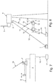
- the embodiment according to Figures 5 to 8 an additional, bottom-side anchoring via the bearing blocks 17, to which ropes 16 are attached, which are guided to the system 2 via rollers or rollers 19 and allow the frame structure 2 or the robot to be adjusted in height.
- a rope 16 is guided to the respective pulley 19 and the frame structure 2.
- the block 17 serving as a bearing block, the desired height of the system 2 can thus be adjusted as desired.
- Ropes 19a can be connected to the frame structure 2.
- Fig. 6 are the components of the embodiment according to Fig. 5 not shown in detail, the bearing blocks 17 being indicated schematically, which are mounted below the frame structure on the bottom side or in a variable manner on a height-adjustable or vertically or horizontally displaceable element.
- the exemplary embodiments described above and shown in the drawings can be modified in any way in order to achieve an adaptation to the level of use or test reliability.
- the system 2 can be implemented in a manner in accordance with the variation of the exemplary embodiments 1 to 4 described above, the frame structure 2 and the system likewise being in the manner described above or from the WO 2014/059964 A1 known way can be designed.
- an additional damper or stabilizer 18, for example acting horizontally or with a horizontal component is provided.
- the damper, spacer or stabilizer 18 can be designed as a telescopically extendable configuration, but can also have a fixed, extended length.
- the tower of the wind energy installation WEA is designated with the reference number 19.
- the spacer 18 can be designed, for example, as a telescopically extendable shock absorber, can additionally or alternatively also be designed as a hydraulically or electrically extendable damper or stabilizer in the horizontal direction.
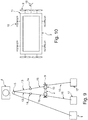
- the stabilizer 18 can be arranged as a damper on the left and / or right of the robot 2 or the frame structure, for example.
- the damper or spacer 18 can also be arranged centrally on the frame 2.
- a damper or spacer 18 can be provided as a pair at one or both or all corners of the frame 2, so that the frame 2 can be cushioned on one side. How out Fig. 10 can be seen, the spacer 18 between the Frame construction 2 can be arranged essentially in the middle and on tower 19.
Landscapes
- Engineering & Computer Science (AREA)
- Life Sciences & Earth Sciences (AREA)
- Sustainable Development (AREA)
- Sustainable Energy (AREA)
- Chemical & Material Sciences (AREA)
- Combustion & Propulsion (AREA)
- Mechanical Engineering (AREA)
- General Engineering & Computer Science (AREA)
- Physics & Mathematics (AREA)
- General Physics & Mathematics (AREA)
- Wind Motors (AREA)
Priority Applications (4)
| Application Number | Priority Date | Filing Date | Title |
|---|---|---|---|
| SI201830324T SI3625452T1 (sl) | 2017-05-17 | 2018-05-08 | Naprava za pregled vetrnih energetskih naprav |
| RS20210668A RS61970B1 (sr) | 2017-05-17 | 2018-05-08 | Uređaj za pregled postrojenja vetrenjače |
| PL18723492T PL3625452T3 (pl) | 2017-05-17 | 2018-05-08 | Sprzęt do inspekcji turbin wiatrowych |
| EP21162803.7A EP3875757A1 (de) | 2017-05-17 | 2018-05-08 | Gerät zur inspektion von windenergieanlagen |
Applications Claiming Priority (2)
| Application Number | Priority Date | Filing Date | Title |
|---|---|---|---|
| DE102017110714.2A DE102017110714A1 (de) | 2017-05-17 | 2017-05-17 | Gerät zur Inspektion von Windenergieanlagen |
| PCT/EP2018/061866 WO2018210632A1 (de) | 2017-05-17 | 2018-05-08 | Gerät zur inspektion von windenergieanlagen |
Related Child Applications (1)
| Application Number | Title | Priority Date | Filing Date |
|---|---|---|---|
| EP21162803.7A Division EP3875757A1 (de) | 2017-05-17 | 2018-05-08 | Gerät zur inspektion von windenergieanlagen |
Publications (2)
| Publication Number | Publication Date |
|---|---|
| EP3625452A1 EP3625452A1 (de) | 2020-03-25 |
| EP3625452B1 true EP3625452B1 (de) | 2021-04-07 |
Family
ID=62143171
Family Applications (2)
| Application Number | Title | Priority Date | Filing Date |
|---|---|---|---|
| EP21162803.7A Withdrawn EP3875757A1 (de) | 2017-05-17 | 2018-05-08 | Gerät zur inspektion von windenergieanlagen |
| EP18723492.7A Active EP3625452B1 (de) | 2017-05-17 | 2018-05-08 | Gerät zur inspektion von windenergieanlagen |
Family Applications Before (1)
| Application Number | Title | Priority Date | Filing Date |
|---|---|---|---|
| EP21162803.7A Withdrawn EP3875757A1 (de) | 2017-05-17 | 2018-05-08 | Gerät zur inspektion von windenergieanlagen |
Country Status (10)
| Country | Link |
|---|---|
| US (1) | US11604056B2 (da) |
| EP (2) | EP3875757A1 (da) |
| DE (3) | DE102017110714A1 (da) |
| DK (1) | DK3625452T3 (da) |
| ES (1) | ES2875392T3 (da) |
| PL (1) | PL3625452T3 (da) |
| PT (1) | PT3625452T (da) |
| RS (1) | RS61970B1 (da) |
| SI (1) | SI3625452T1 (da) |
| WO (1) | WO2018210632A1 (da) |
Families Citing this family (5)
| Publication number | Priority date | Publication date | Assignee | Title |
|---|---|---|---|---|
| US11020772B2 (en) * | 2019-02-05 | 2021-06-01 | William F. Crunk | System and method for cleaning wind turbine blades and solar panels |
| US20210255112A1 (en) * | 2020-02-18 | 2021-08-19 | Infrastructure Preservation Corporation | Robotic inspection system for structural columns |
| US11597077B2 (en) | 2020-07-22 | 2023-03-07 | Saudi Arabian Oil Company | Cable suspended robot for industrial plants |
| US12233545B2 (en) | 2022-03-30 | 2025-02-25 | Saudi Arabian Oil Company | Modular, propelled cable suspended robot for industrial plants and unmanned offshore platforms |
| CN115194746B (zh) * | 2022-07-14 | 2025-05-27 | 哈尔滨工业大学(深圳) | 一种基于高速飞轮的定轴性的自平衡绳驱机器人 |
Family Cites Families (18)
| Publication number | Priority date | Publication date | Assignee | Title |
|---|---|---|---|---|
| US5136784A (en) * | 1990-12-07 | 1992-08-11 | Marantz Jacob J | Vehicle electronic level measuring and display device |
| DE19726408C1 (de) * | 1997-06-21 | 1999-03-18 | Gerhard Reineke Schlosserei Un | Arbeitsbühne |
| DK1583905T3 (da) | 2001-12-06 | 2010-08-02 | Pp Energy Aps | Metode og apparat til behandling af et rotorblad på en vindmølle |
| AU2003258492A1 (en) * | 2002-09-04 | 2004-03-29 | Pp Energy Aps | A method and a device for lifting and/or lowering of objects at a wind turbine or the like and uses hereof |
| US8790468B2 (en) * | 2007-07-13 | 2014-07-29 | Sky Robotics, Inc. | Stabilized vertical surface cleaning |
| US8490749B2 (en) * | 2006-01-27 | 2013-07-23 | Pp Energy Aps | Device for enabling access to a structure above ground level |
| WO2011163498A2 (en) * | 2010-06-23 | 2011-12-29 | Jensen dustin | Wind turbine blade treatment apparatuses and methods |
| US8171809B2 (en) * | 2010-06-25 | 2012-05-08 | General Electric Company | System and method for wind turbine inspection |
| US20110140060A1 (en) * | 2010-11-29 | 2011-06-16 | General Electric Company | System and method for locating a maintenance device approximate an area of interest of a wind turbine |
| KR101422497B1 (ko) * | 2012-06-21 | 2014-07-25 | 삼성중공업 주식회사 | 풍력터빈용 블레이드 유지관리 플랫폼 |
| KR101422498B1 (ko) * | 2012-06-21 | 2014-07-25 | 삼성중공업 주식회사 | 풍력터빈용 블레이드 유지관리 플랫폼 |
| US9790923B2 (en) * | 2012-10-16 | 2017-10-17 | Nina Katharina Krampe | Robot for inspecting rotor blades of wind energy installations |
| SG11201506436RA (en) * | 2013-02-18 | 2015-09-29 | High Wind N V | Device and method for placing a rotor blade of a wind turbine |
| EP2801517A1 (en) * | 2013-05-06 | 2014-11-12 | Siemens Aktiengesellschaft | Underwater module handling apparatus |
| US9494133B2 (en) * | 2013-06-05 | 2016-11-15 | Inventus Holdings, Llc | Method for lowering and raising a wind turbine blade |
| JP6242779B2 (ja) * | 2013-10-09 | 2017-12-06 | 三菱重工業株式会社 | 風力発電装置の機器搬送方法及び風力発電装置 |
| EP3165945B1 (de) * | 2015-11-03 | 2024-01-03 | Leica Geosystems AG | Oberflächenvermessungsgerät zur bestimmung von 3d-koordinaten einer oberfläche |
| EP3495655B1 (en) * | 2017-12-11 | 2020-07-15 | Sulzer & Schmid Laboratories AG | Method and system for testing a lightning protection system of a wind turbine |
-
2017
- 2017-05-17 DE DE102017110714.2A patent/DE102017110714A1/de not_active Withdrawn
-
2018
- 2018-05-08 RS RS20210668A patent/RS61970B1/sr unknown
- 2018-05-08 EP EP21162803.7A patent/EP3875757A1/de not_active Withdrawn
- 2018-05-08 DE DE202018006608.7U patent/DE202018006608U1/de active Active
- 2018-05-08 WO PCT/EP2018/061866 patent/WO2018210632A1/de not_active Ceased
- 2018-05-08 US US16/614,428 patent/US11604056B2/en active Active
- 2018-05-08 DK DK18723492.7T patent/DK3625452T3/da active
- 2018-05-08 EP EP18723492.7A patent/EP3625452B1/de active Active
- 2018-05-08 PT PT187234927T patent/PT3625452T/pt unknown
- 2018-05-08 PL PL18723492T patent/PL3625452T3/pl unknown
- 2018-05-08 SI SI201830324T patent/SI3625452T1/sl unknown
- 2018-05-08 DE DE202018006490.4U patent/DE202018006490U1/de active Active
- 2018-05-08 ES ES18723492T patent/ES2875392T3/es active Active
Non-Patent Citations (1)
| Title |
|---|
| None * |
Also Published As
| Publication number | Publication date |
|---|---|
| WO2018210632A1 (de) | 2018-11-22 |
| DE202018006490U1 (de) | 2020-10-08 |
| PL3625452T3 (pl) | 2021-10-25 |
| DE202018006608U1 (de) | 2021-07-01 |
| EP3875757A1 (de) | 2021-09-08 |
| PT3625452T (pt) | 2021-05-31 |
| US20200333127A1 (en) | 2020-10-22 |
| DE102017110714A1 (de) | 2018-11-22 |
| SI3625452T1 (sl) | 2021-08-31 |
| US11604056B2 (en) | 2023-03-14 |
| DK3625452T3 (da) | 2021-06-21 |
| ES2875392T3 (es) | 2021-11-10 |
| RS61970B1 (sr) | 2021-07-30 |
| EP3625452A1 (de) | 2020-03-25 |
Similar Documents
| Publication | Publication Date | Title |
|---|---|---|
| EP3875757A1 (de) | Gerät zur inspektion von windenergieanlagen | |
| EP3016901B1 (de) | Turmdrehkran und verfahren zur montage eines windturbinen-rotorblattes | |
| EP4151857B1 (de) | Vorrichtung zur lokalen inspektion und/oder reparatur und/oder beschichtung von rotorblättern einer windenergieanlage | |
| EP2746483B1 (de) | Schwingungstilgeranordnurg | |
| EP3137763B1 (de) | Vorrichtung zur steuerung und lenkung von zugdrachen oder rotierenden flügelrädern zur stromerzeugung | |
| EP3935000B1 (de) | Messvorrichtung zum vermessen eines aufzugschachts und verwendung der messvorrichtung zum vermessen eines aufzugschachts | |
| DE102009028885B4 (de) | Geführter Winddrachen zur Erhöhung der Leistungsabgabe von Windenergieanlagen | |
| EP3049362A1 (de) | Vorrichtung und verfahren zur handhabung, montage oder demontage von komponenten einer windkraftanlage | |
| DE10051513A1 (de) | Windpark | |
| DE102010060639A1 (de) | Arbeitsbühnenanlage | |
| AT510762A1 (de) | Seilzugeinrichtung, insbesondere prospektzuganlage für eine bühne oder dgl. | |
| DE102011100912B4 (de) | Rotorblatt-Befahranlage | |
| EP3948204B1 (de) | Vorrichtung und verfahren für die demontage/remontage von rotorlagern eines gebläses eines windkanals | |
| EP3399185A1 (de) | Einhausung für eine gondel einer windenergieanlage | |
| WO2014198940A1 (de) | Stablisierungssystem für kabinen eines fassadenaufzuges | |
| WO2020057864A1 (de) | Windenergieanlagen-turmsegment für einen windenergieanlagen-turm und verfahren | |
| EP2735734A2 (de) | Windkraftmaschine mit vertikalstehenden Flügeln | |
| EP3574166B1 (de) | Rotorblattbefahranlage und verfahren zur positionierung der wartungskammer einer rotorblattbefahranlage | |
| DE102017110006B4 (de) | Außenwinde für einen Hubschrauber mit Einrichtungen zur Stabilisierung einer an die Außenwinde angehängten Außenlast und Hubschrauber mit einer solchen Außenwinde | |
| DE202011100388U1 (de) | Rotorblatt-Befahranlage | |
| EP3839252B1 (de) | Montagevorrichtung für rotorblätter einer windenergieanlage | |
| DE102010060294A1 (de) | Arbeitsbühne | |
| DE102020130409A1 (de) | Seilroboter mit Arbeitskorb | |
| DE102004009401A1 (de) | Kabelkran | |
| EP4577741A1 (de) | Verfahren für einen wechsel der flügel einer windkraftanlage |
Legal Events
| Date | Code | Title | Description |
|---|---|---|---|
| REG | Reference to a national code |
Ref country code: DE Ref legal event code: R138 Ref document number: 202018006490 Country of ref document: DE Free format text: GERMAN DOCUMENT NUMBER IS 502018004707 |
|
| STAA | Information on the status of an ep patent application or granted ep patent |
Free format text: STATUS: UNKNOWN |
|
| STAA | Information on the status of an ep patent application or granted ep patent |
Free format text: STATUS: THE INTERNATIONAL PUBLICATION HAS BEEN MADE |
|
| PUAI | Public reference made under article 153(3) epc to a published international application that has entered the european phase |
Free format text: ORIGINAL CODE: 0009012 |
|
| STAA | Information on the status of an ep patent application or granted ep patent |
Free format text: STATUS: REQUEST FOR EXAMINATION WAS MADE |
|
| 17P | Request for examination filed |
Effective date: 20191216 |
|
| AK | Designated contracting states |
Kind code of ref document: A1 Designated state(s): AL AT BE BG CH CY CZ DE DK EE ES FI FR GB GR HR HU IE IS IT LI LT LU LV MC MK MT NL NO PL PT RO RS SE SI SK SM TR |
|
| RAP1 | Party data changed (applicant data changed or rights of an application transferred) |
Owner name: COMPOSITE CONSULT GMBH |
|
| RIN1 | Information on inventor provided before grant (corrected) |
Inventor name: KRAMPE, NINA KATHARINA Inventor name: KRAMPE, TIMOTHY |
|
| GRAP | Despatch of communication of intention to grant a patent |
Free format text: ORIGINAL CODE: EPIDOSNIGR1 |
|
| STAA | Information on the status of an ep patent application or granted ep patent |
Free format text: STATUS: GRANT OF PATENT IS INTENDED |
|
| INTG | Intention to grant announced |
Effective date: 20201021 |
|
| GRAS | Grant fee paid |
Free format text: ORIGINAL CODE: EPIDOSNIGR3 |
|
| GRAA | (expected) grant |
Free format text: ORIGINAL CODE: 0009210 |
|
| STAA | Information on the status of an ep patent application or granted ep patent |
Free format text: STATUS: THE PATENT HAS BEEN GRANTED |
|
| AK | Designated contracting states |
Kind code of ref document: B1 Designated state(s): AL AT BE BG CH CY CZ DE DK EE ES FI FR GB GR HR HU IE IS IT LI LT LU LV MC MK MT NL NO PL PT RO RS SE SI SK SM TR |
|
| REG | Reference to a national code |
Ref country code: GB Ref legal event code: FG4D Free format text: NOT ENGLISH |
|
| REG | Reference to a national code |
Ref country code: AT Ref legal event code: REF Ref document number: 1380016 Country of ref document: AT Kind code of ref document: T Effective date: 20210415 Ref country code: CH Ref legal event code: EP |
|
| REG | Reference to a national code |
Ref country code: DE Ref legal event code: R096 Ref document number: 502018004707 Country of ref document: DE |
|
| REG | Reference to a national code |
Ref country code: IE Ref legal event code: FG4D Free format text: LANGUAGE OF EP DOCUMENT: GERMAN |
|
| REG | Reference to a national code |
Ref country code: PT Ref legal event code: SC4A Ref document number: 3625452 Country of ref document: PT Date of ref document: 20210531 Kind code of ref document: T Free format text: AVAILABILITY OF NATIONAL TRANSLATION Effective date: 20210524 |
|
| REG | Reference to a national code |
Ref country code: DK Ref legal event code: T3 Effective date: 20210618 |
|
| REG | Reference to a national code |
Ref country code: FI Ref legal event code: FGE |
|
| REG | Reference to a national code |
Ref country code: NL Ref legal event code: FP |
|
| REG | Reference to a national code |
Ref country code: SE Ref legal event code: TRGR |
|
| REG | Reference to a national code |
Ref country code: LT Ref legal event code: MG9D |
|
| REG | Reference to a national code |
Ref country code: SK Ref legal event code: T3 Ref document number: E 37436 Country of ref document: SK |
|
| PG25 | Lapsed in a contracting state [announced via postgrant information from national office to epo] |
Ref country code: BG Free format text: LAPSE BECAUSE OF FAILURE TO SUBMIT A TRANSLATION OF THE DESCRIPTION OR TO PAY THE FEE WITHIN THE PRESCRIBED TIME-LIMIT Effective date: 20210707 Ref country code: HR Free format text: LAPSE BECAUSE OF FAILURE TO SUBMIT A TRANSLATION OF THE DESCRIPTION OR TO PAY THE FEE WITHIN THE PRESCRIBED TIME-LIMIT Effective date: 20210407 Ref country code: LT Free format text: LAPSE BECAUSE OF FAILURE TO SUBMIT A TRANSLATION OF THE DESCRIPTION OR TO PAY THE FEE WITHIN THE PRESCRIBED TIME-LIMIT Effective date: 20210407 |
|
| REG | Reference to a national code |
Ref country code: ES Ref legal event code: FG2A Ref document number: 2875392 Country of ref document: ES Kind code of ref document: T3 Effective date: 20211110 |
|
| PG25 | Lapsed in a contracting state [announced via postgrant information from national office to epo] |
Ref country code: GR Free format text: LAPSE BECAUSE OF FAILURE TO SUBMIT A TRANSLATION OF THE DESCRIPTION OR TO PAY THE FEE WITHIN THE PRESCRIBED TIME-LIMIT Effective date: 20210708 Ref country code: LV Free format text: LAPSE BECAUSE OF FAILURE TO SUBMIT A TRANSLATION OF THE DESCRIPTION OR TO PAY THE FEE WITHIN THE PRESCRIBED TIME-LIMIT Effective date: 20210407 Ref country code: NO Free format text: LAPSE BECAUSE OF FAILURE TO SUBMIT A TRANSLATION OF THE DESCRIPTION OR TO PAY THE FEE WITHIN THE PRESCRIBED TIME-LIMIT Effective date: 20210707 |
|
| REG | Reference to a national code |
Ref country code: CH Ref legal event code: PL |
|
| REG | Reference to a national code |
Ref country code: DE Ref legal event code: R097 Ref document number: 502018004707 Country of ref document: DE |
|
| PG25 | Lapsed in a contracting state [announced via postgrant information from national office to epo] |
Ref country code: EE Free format text: LAPSE BECAUSE OF FAILURE TO SUBMIT A TRANSLATION OF THE DESCRIPTION OR TO PAY THE FEE WITHIN THE PRESCRIBED TIME-LIMIT Effective date: 20210407 Ref country code: RO Free format text: LAPSE BECAUSE OF FAILURE TO SUBMIT A TRANSLATION OF THE DESCRIPTION OR TO PAY THE FEE WITHIN THE PRESCRIBED TIME-LIMIT Effective date: 20210407 Ref country code: SM Free format text: LAPSE BECAUSE OF FAILURE TO SUBMIT A TRANSLATION OF THE DESCRIPTION OR TO PAY THE FEE WITHIN THE PRESCRIBED TIME-LIMIT Effective date: 20210407 Ref country code: LI Free format text: LAPSE BECAUSE OF NON-PAYMENT OF DUE FEES Effective date: 20210531 Ref country code: MC Free format text: LAPSE BECAUSE OF FAILURE TO SUBMIT A TRANSLATION OF THE DESCRIPTION OR TO PAY THE FEE WITHIN THE PRESCRIBED TIME-LIMIT Effective date: 20210407 Ref country code: CZ Free format text: LAPSE BECAUSE OF FAILURE TO SUBMIT A TRANSLATION OF THE DESCRIPTION OR TO PAY THE FEE WITHIN THE PRESCRIBED TIME-LIMIT Effective date: 20210407 Ref country code: CH Free format text: LAPSE BECAUSE OF NON-PAYMENT OF DUE FEES Effective date: 20210531 |
|
| PLBE | No opposition filed within time limit |
Free format text: ORIGINAL CODE: 0009261 |
|
| STAA | Information on the status of an ep patent application or granted ep patent |
Free format text: STATUS: NO OPPOSITION FILED WITHIN TIME LIMIT |
|
| 26N | No opposition filed |
Effective date: 20220110 |
|
| PG25 | Lapsed in a contracting state [announced via postgrant information from national office to epo] |
Ref country code: AL Free format text: LAPSE BECAUSE OF FAILURE TO SUBMIT A TRANSLATION OF THE DESCRIPTION OR TO PAY THE FEE WITHIN THE PRESCRIBED TIME-LIMIT Effective date: 20210407 |
|
| PGFP | Annual fee paid to national office [announced via postgrant information from national office to epo] |
Ref country code: SK Payment date: 20220502 Year of fee payment: 5 Ref country code: RS Payment date: 20220429 Year of fee payment: 5 Ref country code: PT Payment date: 20220428 Year of fee payment: 5 |
|
| PGFP | Annual fee paid to national office [announced via postgrant information from national office to epo] |
Ref country code: TR Payment date: 20220505 Year of fee payment: 5 Ref country code: SI Payment date: 20220426 Year of fee payment: 5 Ref country code: PL Payment date: 20220415 Year of fee payment: 5 |
|
| PG25 | Lapsed in a contracting state [announced via postgrant information from national office to epo] |
Ref country code: CY Free format text: LAPSE BECAUSE OF FAILURE TO SUBMIT A TRANSLATION OF THE DESCRIPTION OR TO PAY THE FEE WITHIN THE PRESCRIBED TIME-LIMIT Effective date: 20210407 |
|
| PG25 | Lapsed in a contracting state [announced via postgrant information from national office to epo] |
Ref country code: HU Free format text: LAPSE BECAUSE OF FAILURE TO SUBMIT A TRANSLATION OF THE DESCRIPTION OR TO PAY THE FEE WITHIN THE PRESCRIBED TIME-LIMIT; INVALID AB INITIO Effective date: 20180508 |
|
| REG | Reference to a national code |
Ref country code: SK Ref legal event code: MM4A Ref document number: E 37436 Country of ref document: SK Effective date: 20230508 |
|
| PGFP | Annual fee paid to national office [announced via postgrant information from national office to epo] |
Ref country code: LU Payment date: 20231129 Year of fee payment: 6 |
|
| PG25 | Lapsed in a contracting state [announced via postgrant information from national office to epo] |
Ref country code: SK Free format text: LAPSE BECAUSE OF NON-PAYMENT OF DUE FEES Effective date: 20230508 |
|
| PGFP | Annual fee paid to national office [announced via postgrant information from national office to epo] |
Ref country code: GB Payment date: 20231129 Year of fee payment: 6 |
|
| PGFP | Annual fee paid to national office [announced via postgrant information from national office to epo] |
Ref country code: ES Payment date: 20231129 Year of fee payment: 6 |
|
| PGFP | Annual fee paid to national office [announced via postgrant information from national office to epo] |
Ref country code: IS Payment date: 20231129 Year of fee payment: 6 |
|
| PG25 | Lapsed in a contracting state [announced via postgrant information from national office to epo] |
Ref country code: SK Free format text: LAPSE BECAUSE OF NON-PAYMENT OF DUE FEES Effective date: 20230508 Ref country code: SI Free format text: LAPSE BECAUSE OF NON-PAYMENT OF DUE FEES Effective date: 20230509 Ref country code: RS Free format text: LAPSE BECAUSE OF NON-PAYMENT OF DUE FEES Effective date: 20230508 Ref country code: PT Free format text: LAPSE BECAUSE OF NON-PAYMENT OF DUE FEES Effective date: 20231108 |
|
| PGFP | Annual fee paid to national office [announced via postgrant information from national office to epo] |
Ref country code: SE Payment date: 20231129 Year of fee payment: 6 Ref country code: DK Payment date: 20231129 Year of fee payment: 6 Ref country code: DE Payment date: 20231124 Year of fee payment: 6 Ref country code: AT Payment date: 20231128 Year of fee payment: 6 Ref country code: NL Payment date: 20231129 Year of fee payment: 6 Ref country code: IT Payment date: 20231128 Year of fee payment: 6 Ref country code: IE Payment date: 20231128 Year of fee payment: 6 Ref country code: FR Payment date: 20231129 Year of fee payment: 6 Ref country code: FI Payment date: 20231129 Year of fee payment: 6 |
|
| PGFP | Annual fee paid to national office [announced via postgrant information from national office to epo] |
Ref country code: BE Payment date: 20231129 Year of fee payment: 6 |
|
| REG | Reference to a national code |
Ref country code: SI Ref legal event code: KO00 Effective date: 20240222 |
|
| PG25 | Lapsed in a contracting state [announced via postgrant information from national office to epo] |
Ref country code: MK Free format text: LAPSE BECAUSE OF FAILURE TO SUBMIT A TRANSLATION OF THE DESCRIPTION OR TO PAY THE FEE WITHIN THE PRESCRIBED TIME-LIMIT Effective date: 20210407 |
|
| PG25 | Lapsed in a contracting state [announced via postgrant information from national office to epo] |
Ref country code: MT Free format text: LAPSE BECAUSE OF FAILURE TO SUBMIT A TRANSLATION OF THE DESCRIPTION OR TO PAY THE FEE WITHIN THE PRESCRIBED TIME-LIMIT Effective date: 20210407 |
|
| REG | Reference to a national code |
Ref country code: DE Ref legal event code: R119 Ref document number: 502018004707 Country of ref document: DE |
|
| REG | Reference to a national code |
Ref country code: DK Ref legal event code: EBP Effective date: 20240531 Ref country code: SE Ref legal event code: EUG |
|
| REG | Reference to a national code |
Ref country code: NL Ref legal event code: MM Effective date: 20240601 |
|
| REG | Reference to a national code |
Ref country code: AT Ref legal event code: MM01 Ref document number: 1380016 Country of ref document: AT Kind code of ref document: T Effective date: 20240508 |
|
| PG25 | Lapsed in a contracting state [announced via postgrant information from national office to epo] |
Ref country code: LU Free format text: LAPSE BECAUSE OF NON-PAYMENT OF DUE FEES Effective date: 20240508 Ref country code: FI Free format text: LAPSE BECAUSE OF NON-PAYMENT OF DUE FEES Effective date: 20240508 Ref country code: PL Free format text: LAPSE BECAUSE OF NON-PAYMENT OF DUE FEES Effective date: 20230508 |
|
| PG25 | Lapsed in a contracting state [announced via postgrant information from national office to epo] |
Ref country code: AT Free format text: LAPSE BECAUSE OF NON-PAYMENT OF DUE FEES Effective date: 20240508 |
|
| GBPC | Gb: european patent ceased through non-payment of renewal fee |
Effective date: 20240508 |
|
| PG25 | Lapsed in a contracting state [announced via postgrant information from national office to epo] |
Ref country code: PL Free format text: LAPSE BECAUSE OF NON-PAYMENT OF DUE FEES Effective date: 20230508 Ref country code: LU Free format text: LAPSE BECAUSE OF NON-PAYMENT OF DUE FEES Effective date: 20240508 Ref country code: FI Free format text: LAPSE BECAUSE OF NON-PAYMENT OF DUE FEES Effective date: 20240508 Ref country code: AT Free format text: LAPSE BECAUSE OF NON-PAYMENT OF DUE FEES Effective date: 20240508 |
|
| PG25 | Lapsed in a contracting state [announced via postgrant information from national office to epo] |
Ref country code: NL Free format text: LAPSE BECAUSE OF NON-PAYMENT OF DUE FEES Effective date: 20240601 |
|
| REG | Reference to a national code |
Ref country code: BE Ref legal event code: MM Effective date: 20240531 |
|
| PG25 | Lapsed in a contracting state [announced via postgrant information from national office to epo] |
Ref country code: DE Free format text: LAPSE BECAUSE OF NON-PAYMENT OF DUE FEES Effective date: 20241203 |
|
| PG25 | Lapsed in a contracting state [announced via postgrant information from national office to epo] |
Ref country code: DK Free format text: LAPSE BECAUSE OF NON-PAYMENT OF DUE FEES Effective date: 20240531 |
|
| PG25 | Lapsed in a contracting state [announced via postgrant information from national office to epo] |
Ref country code: IE Free format text: LAPSE BECAUSE OF NON-PAYMENT OF DUE FEES Effective date: 20240508 |
|
| PG25 | Lapsed in a contracting state [announced via postgrant information from national office to epo] |
Ref country code: BE Free format text: LAPSE BECAUSE OF NON-PAYMENT OF DUE FEES Effective date: 20240531 |
|
| PG25 | Lapsed in a contracting state [announced via postgrant information from national office to epo] |
Ref country code: FR Free format text: LAPSE BECAUSE OF NON-PAYMENT OF DUE FEES Effective date: 20240531 |
|
| PG25 | Lapsed in a contracting state [announced via postgrant information from national office to epo] |
Ref country code: IT Free format text: LAPSE BECAUSE OF NON-PAYMENT OF DUE FEES Effective date: 20240508 Ref country code: GB Free format text: LAPSE BECAUSE OF NON-PAYMENT OF DUE FEES Effective date: 20240508 |
|
| REG | Reference to a national code |
Ref country code: ES Ref legal event code: FD2A Effective date: 20250627 |
|
| PG25 | Lapsed in a contracting state [announced via postgrant information from national office to epo] |
Ref country code: ES Free format text: LAPSE BECAUSE OF NON-PAYMENT OF DUE FEES Effective date: 20240509 |
|
| PG25 | Lapsed in a contracting state [announced via postgrant information from national office to epo] |
Ref country code: SE Free format text: LAPSE BECAUSE OF NON-PAYMENT OF DUE FEES Effective date: 20240509 |