EP3625460B1 - Dichtungsvorrichtung für ein turbomaschinengehäuse - Google Patents
Dichtungsvorrichtung für ein turbomaschinengehäuse Download PDFInfo
- Publication number
- EP3625460B1 EP3625460B1 EP18726001.3A EP18726001A EP3625460B1 EP 3625460 B1 EP3625460 B1 EP 3625460B1 EP 18726001 A EP18726001 A EP 18726001A EP 3625460 B1 EP3625460 B1 EP 3625460B1
- Authority
- EP
- European Patent Office
- Prior art keywords
- annular
- casing
- inner cylindrical
- seal
- cylindrical surface
- Prior art date
- Legal status (The legal status is an assumption and is not a legal conclusion. Google has not performed a legal analysis and makes no representation as to the accuracy of the status listed.)
- Active
Links
Images

Classifications
-
- F—MECHANICAL ENGINEERING; LIGHTING; HEATING; WEAPONS; BLASTING
- F04—POSITIVE - DISPLACEMENT MACHINES FOR LIQUIDS; PUMPS FOR LIQUIDS OR ELASTIC FLUIDS
- F04D—NON-POSITIVE-DISPLACEMENT PUMPS
- F04D17/00—Radial-flow pumps, e.g. centrifugal pumps; Helico-centrifugal pumps
- F04D17/08—Centrifugal pumps
- F04D17/10—Centrifugal pumps for compressing or evacuating
- F04D17/12—Multi-stage pumps
- F04D17/122—Multi-stage pumps the individual rotor discs being, one for each stage, on a common shaft and axially spaced, e.g. conventional centrifugal multi- stage compressors
-
- F—MECHANICAL ENGINEERING; LIGHTING; HEATING; WEAPONS; BLASTING
- F04—POSITIVE - DISPLACEMENT MACHINES FOR LIQUIDS; PUMPS FOR LIQUIDS OR ELASTIC FLUIDS
- F04D—NON-POSITIVE-DISPLACEMENT PUMPS
- F04D29/00—Details, component parts, or accessories
- F04D29/08—Sealings
- F04D29/083—Sealings especially adapted for elastic fluid pumps
-
- F—MECHANICAL ENGINEERING; LIGHTING; HEATING; WEAPONS; BLASTING
- F04—POSITIVE - DISPLACEMENT MACHINES FOR LIQUIDS; PUMPS FOR LIQUIDS OR ELASTIC FLUIDS
- F04D—NON-POSITIVE-DISPLACEMENT PUMPS
- F04D29/00—Details, component parts, or accessories
- F04D29/40—Casings; Connections of working fluid
- F04D29/42—Casings; Connections of working fluid for radial or helico-centrifugal pumps
- F04D29/4206—Casings; Connections of working fluid for radial or helico-centrifugal pumps especially adapted for elastic fluid pumps
Definitions
- Aspect of the present invention relate to a seal apparatus for a turbomachine casing, and more particularly, to a seal apparatus having an annular body that includes first and second annular body portions and an appendage that extends axially from the first annular body portion wherein an inner annular surface of the appendage and an outer annular surface of the second annular body define an annular cavity wherein at least a portion of the appendage may be configured to be displaced radially outward in order to maintain contact with first and second inner cylindrical surfaces of the casing during radial expansion of the casing.
- Turbomachines such as centrifugal compressors generally include compressor components (e.g., impellers) mounted on a rotary shaft and disposed within a casing.
- the rotary shaft typically extends through an opening at one or both ends of the casing.
- a plug-like body commonly referred to as a compressor head, may be inserted into the opening(s) to close and seal the casing opening.
- the compressor head may be axially retained in the compressor by a plurality of shear keys.
- one or more O-rings may be disposed between an outer surface of the compressor head and an inner surface of the casing.
- high pressure compressors e.g., 10,000 psi (68.9 MPa)
- the casing grows radially outward while the compressor head grows little or none.
- the resulting increasing radial gap between the compressor head and casing may cause the seal provided by the O-rings to fail by extrusion through the radial gap.
- first and second features are formed in direct contact
- additional features may be formed interposing the first and second features, such that the first and second features may not be in direct contact.
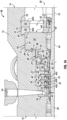
- FIG 1A illustrates a cross-sectional view of an exemplary turbomachine 10, according to one or more embodiments.
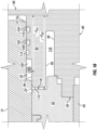
- Figure 1B illustrates an enlarged cross-sectional view of the portion of the turbomachine 10 indicated by the box labeled 1B in Figure 1A , according to one or more embodiments of the disclosure.
- the turbomachine 10 may be a centrifugal compressor; however, aspects of the present disclosure are not limited thereto, and other illustrative turbomachines 10 may include, but are not limited to, an axial flow compressor, a back-to-back compressor, a rotary separator, and a pump.
- the turbomachine 10 may be configured to draw a process fluid therein, compress the process fluid, and to discharge the process fluid therefrom at a higher pressure. Accordingly, in some embodiments, the process fluid flowing therethrough and subsequently discharged from the turbomachine 10 may have a pressure of about 10,000 psi (68.9 MPa) or greater.
- Illustrative process fluids provided to the turbomachine 10 may include, but are not limited to, methane, natural gas, air, oxygen, nitrogen, hydrogen, and carbon dioxide.
- the turbomachine 10 includes a casing 12 having opposing axial ends 14, 16 and a central axis 18 extending between the opposing axial ends 14, 16.
- the casing 12 includes a plurality of inner cylindrical surfaces (three indicated 20, 22, 24) having different internal diameters.
- the plurality of inner cylindrical surfaces 20, 22, 24 may include a first inner cylindrical surface 20, a second inner cylindrical surface 22, and a third inner cylindrical surface 24 having respective internal diameters such that the first inner cylindrical surface 20, the second inner cylindrical surface 22, and the third inner cylindrical surface 24 are radially offset from one another.
- the first inner cylindrical surface 20, the second inner cylindrical surface 22, and the third inner cylindrical surface 24 may define a central bore 26 extending along the central axis 18.
- a first cylindrical portion of the central bore 26 may be defined by the first inner cylindrical surface 20 and the second inner cylindrical surface 22 and may be referred to as the working chamber 28.
- a second cylindrical portion of the central bore 26 may be defined by the third inner cylindrical surface 24 and may be referred to as the casing opening 30.
- the internal diameter of the casing opening 30 may be greater than the internal diameter of the working chamber 28.
- the central bore 26 may be a stepped bore. Accordingly, an annular wall 32 of the casing 12 may extend radially between the first inner cylindrical surface 20 and the third inner cylindrical surface 24. Additionally, as the first inner cylindrical surface 20 and the second inner cylindrical surface 22 may be radially offset from one another, a shoulder or annular wall 34 may extend radially therebetween.
- the working chamber 28 generally houses a modular bundle 36 containing the working components of the turbomachine 10.
- the casing opening 30 may extend from the axial end 14 of the casing 12 to the working chamber 28, thereby providing a means for insertion or extraction of the modular bundle 36.
- the modular bundle 36 may include, amongst other working components, a rotary shaft 38 and one or more compression stages (three shown 40a-c), each stage 40a-c including an impeller 42 mounted to the rotatable shaft 38 and at least one stationary diaphragm 44 coupled to a bundle housing 46 and providing outlet and inlet flow passages 48 between each impeller 42.
- the modular bundle 36 may further include a plurality of seals including a main seal 50 disposed in a sealing relationship with the rotary shaft 38, and a seal carrier 52 provided to support the main seal 50.
- the casing 12 may further define a radial fluid inlet 54 fluidly coupling a process fluid source or an upstream process component (not shown) with the first compression stage 40a and an outlet chamber or volute 56 fluidly connected with the last compression stage 40c.
- the turbomachine 10 further includes a seal apparatus 58 disposed within the central bore 26 and engageable with the casing 12 to close and seal the working chamber 28 from the casing opening 30 such that any leakage of process fluid from the working chamber 28 into the casing opening 30 is substantially reduced or prevented.
- the seal apparatus 58 includes an annular body 60 defining a center opening 62 through which the rotary shaft 38 may extend.
- the annular body 60 has a center axis 64, and as arranged about the rotary shaft 38, the center axis 64 of the annular body 60 and the central axis 18 of the casing 12 may be coaxial.
- the annular body 60 may be formed without a center opening 62 and may be used instead to close and seal other types of casing openings 30 (i.e., other than an opening surrounding the rotary shaft 38).
- the seal apparatus 58 is configured or constructed to substantially obstruct or seal the casing opening 30 so as to at least substantially prevent high pressure fluid from flowing out of the working chamber 28 through the casing opening 30.
- the annular body 60 may have a substantial axial thickness such that the seal apparatus 58 may be capable of resisting relatively high pressure without a substantial deformation or failure of the seal apparatus 58.
- the annular body 60 includes a first annular body portion 66 including a first annular sidewall 68, a second annular sidewall 70 axially opposing the first annular sidewall 68, and an outer annular surface 72 extending between the first annular sidewall 68 and the second annular sidewall 70.
- the sealing apparatus 58 may be disposed within the central bore 26 and between the opposing axial ends 14, 16 of the casing 12 such that the outer annular surface 72 abuts the third inner cylindrical surface 24 and the first annular sidewall 68 abuts or is adjacent the annular wall 32 of the casing 12 extending radially between the first inner cylindrical sidewall 20 and the third inner cylindrical sidewall 24.
- the first annular sidewall 68 may be coupled to the annular wall 32 via one or more retainers (one shown 74). In one or more embodiments, the first annular sidewall 68 may be coupled to the annular wall 32 via a plurality of retainers 74 circumferentially disposed about the rotary shaft 38.
- the retainers 74 may be bolts. In other embodiments, the retainers may be dowels, pins, or like components.
- the retainer(s) 74 may be configured to at least prevent rotational displacement of the annular body 60 about the central axis 18.
- the second annular sidewall 70 may abut a retainer 76 disposed in an annular groove 78 defined by the third inner cylindrical surface 24 at the casing opening 30.
- the retainer 76 may include two rings 80, 82, the first or annular shear ring 80 having an axial lip 84 disposed or disposable between a portion of the first annular body portion 66 and the annular groove 78.
- Each shear ring 80, 82 may be formed of a plurality of arcuate segments 80a, 82a (only one each shown), spaced circumferentially about the central axis 18.
- the annular shear rings 80, 82 may be configured to retain the seal apparatus 58 within the central bore 26 during operation of the turbomachine 10. During extraction of the modular bundle 36, a sufficient axial force may be applied to the modular bundle 36 to shear the annular shear rings 80, 82 and axially slide the seal apparatus 58 and the modular bundle 36 from the turbomachine 10.
- the annular body 60 also includes a second annular body portion 86 extending axially from the first annular body portion 66 and having an outer annular surface 88 radially offset from the outer annular surface 72 of the first annular body portion 66.
- the second annular body portion 86 may be disposed in the working chamber 28 of the central bore 26 adjacent the seal carrier 52.
- an axial end 90 of the second annular body portion 86 may be coupled to the seal carrier 52 via one or more mechanical fasteners (one shown 92).
- the axial end 90 of the second annular body portion 86 may be coupled to the seal carrier 52 via a plurality of mechanical fasteners 92 circumferentially disposed about the rotary shaft 38.
- the mechanical fasteners 92 may be bolts, such as, for example, tie bolts. In other embodiments, the mechanical fasteners 92 may be dowels, pins, or like components.
- the annular body 60 further includes an appendage 94 extending axially from the first annular body portion 66 and having an outer annular surface 96 and an inner annular surface 98.
- the outer annular surface of the appendage 94 defines a plurality of annular grooves 100, 102, 104.
- a plurality of annular seals 106, 108, 110 is disposed within the respective annular grooves 100, 102, 104.
- each of the annular seals 106, 108, 110 extends radially from the respective annular groove 100, 102, 104 and engage the first inner cylindrical surface 20 of the casing 12 in order to provide a seal between the appendage 94 and the first inner cylindrical surface 20.
- the annular seals 106, 108, 110 may be constructed from a compressible polymer material in one or more embodiments.
- the annular seals 106, 108, 110 may be O-rings.
- the annular seals 106, 108, 110 may be constructed from a compressible non-polymer material.
- the plurality of annular seals 106, 108, 110 include a primary annular seal 106 and one or more secondary annular seals (two shown 108 and 110).
- the primary annular seal 106 is disposed in the annular groove 100 proximal an end portion 112 of the appendage 94 distal the first annular body portion 66.
- the end portion 112 of the appendage 94 may engage or contact the second inner cylindrical surface 22 of the casing 12.
- the end portion 112 is used to locate the appendage 94 relative to the second inner cylindrical surface 22.
- the primary annular seal 106 may be subject to a maximum pressure of the process fluid flowing through the turbomachine 10. Accordingly, the primary annular seal 106 and the respective annular groove 100 in which the primary annular seal 106 is disposed is greater in size than the secondary seal(s) 108, 110and the respective annular grooves 102, 104 in which the secondary annular seals 108, 110 are disposed.
- the primary annular seal 106 has a greater external diameter than an external diameter of each of the secondary annular seals 108, 110. Accordingly, as arranged, each of the secondary annular seals 108, 110 may see a pressure equal to or less than the maximum pressure seen by the primary annular seal 106.
- the secondary seals 108, 110 may be "step down" seals in that the secondary seal 110 may see a lower pressure than the previous secondary annular seal 108. In other embodiments, the secondary annular seals 108, 110 may be utilized as back-up seals in case of failure of the primary annular seal 106.
- the outer annular surface 96 of the appendage 94 and the first inner cylindrical surface 20 of the casing 12 further define a port 114 disposed between adjacent annular seals 106, 108 or 108, 110.
- the port 114 may be disposed between the primary seal 106 and an adjacent secondary seal 108.
- the port 114 may be disposed between adjacent secondary seals 108, 110.
- the port 114 may be fluidly coupled to a lower pressure environment within the casing 12 of the turbomachine 10, or in other embodiments, the port 114 may be fluidly coupled to a lower pressure environment external of the casing 12 of the turbomachine 10 via one or more flowpaths defined in the casing 12.
- the port 114 may be fluidly coupled to the atmosphere external of the casing 12, a flare, an inlet of another process component, or any other suitable pressure sink.
- the port 114 may be fluidly coupled to a stage 40a-c in the working chamber 28.
- the port 114 may be configured as a component of a leak detection system (not shown) for the annular seals 106, 108, 110.
- the port 114 may be configured as a vent for leakage of process fluid within the turbomachine 10.
- the inner annular surface 98 of the appendage 94 and the outer annular surface 88 of the second annular body portion 86 define an annular cavity 116 therebetween.
- the annular cavity 116 may be bounded axially by the seal carrier 52 and the first annular body portion 66.
- the annular cavity 116 may be fluidly coupled with at least one stage 40a-c. In one or more embodiments, the annular cavity 116 may be fluidly coupled with the last stage 40c such that a pressurized process fluid may be directed to the annular cavity 116.
- the annular cavity 116 may be configured to receive the pressurized process fluid therein, thereby creating a pressure differential across the appendage 94.
- the casing 12 of the turbomachine 10 may radially expand in response to the generation of the pressurized process fluid.
- At least a portion of the appendage 94 is configured to be displaced radially outward due to the pressure differential thereacross in order to maintain contact with the first inner cylindrical surface 20 and the second inner cylindrical surface 22 of the casing 12 during radial expansion of the casing 12.
- the appendage 94 may maintain sealing engagement of the annular seals 106, 108, 110 with the first inner cylindrical surface 20 of the casing 12 during radial expansion of the casing 12.
- the primary annular seal 106 may be disposed in the annular groove 100 at a first axial distance D A1 from the first annular body portion 66.
- An end portion 118 of the annular cavity 116 distal the first annular body portion 66 may be at a second axial distance D A2 from the first annular body portion 66. Accordingly, in one or more embodiments, the second axial distance D A2 may be greater than the first axial distance D A1 .
- the working chamber 28 may contain highpressure process fluid, which often exerts a pressure on the casing 12 sufficient to cause the casing 12, including the plurality of inner cylindrical surfaces 20, 22, 24 to expand radially outwardly, as indicated by arrow A R in FIG. 1B .
- the inner cylindrical surfaces 20, 22, 24 may be displaced radially outward from the appendage 94.
- the appendage 94 of the sealing apparatus 58 is configured to move radially outward with the radial expansion of the casing 12, thereby maintaining sealing engagement with the inner cylindrical surface 22 of the casing 12, thereby substantially eliminating any space between the appendage 94 and the inner cylindrical surfaces 20, 22, thus acting to prevent leakage of fluid from the working chamber 28.
- Figure 2 illustrates a flowchart depicting a method 200 which does not form part of the claimed invention for sealing a turbomachine casing during radial expansion of the turbomachine casing, according to one or more embodiments disclosed.
- the method may include disposing a plurality of annular seals within respective annular grooves defined by an outer annular surface of an appendage of a seal apparatus, as at 202.
- the seal apparatus may include a first annular body portion from which the appendage and a second annular body portion axially each extend.
- the method 200 may also include disposing the sealing apparatus within a central bore of the turbomachine casing, as at 204.
- the central bore may be defined by a first inner cylindrical surface, a second cylindrical surface, and a third cylindrical surface of the turbomachine casing.
- the first inner cylindrical surface, a second cylindrical surface, and a third cylindrical surface may be radially offset from one another.
- the method 200 may further include sealingly engaging the plurality of seals with the first inner cylindrical surface of the turbomachine casing, as at 206, and engaging an end portion of the appendage with the second inner cylindrical surface of the turbomachine casing, as at 208.
- the method 200 may also include pressurizing an annular cavity defined by an inner annular surface of an appendage of the sealing apparatus and an outer annular surface of the second annular body portion to form a pressure differential across the appendage, as at 210.
- the method 200 may further include expanding the appendage radially outward in response to the pressure differential, thereby (i) maintaining contact of the end portion of the appendage with the second inner cylindrical surface of the turbomachine casing, and (ii) maintaining sealing engagement of the plurality of annular seals with the first inner cylindrical surface of the turbomachine casing during the radial expansion of the turbomachine casing.
- the method 200 may include further include drawing a process fluid into one or more impellers coupled to a rotating shaft extending along a center axis of the turbomachine casing to form a pressurized process fluid.
- the method 200 may further include fluidly coupling a port defined by the first inner cylindrical surface of the turbomachine casing and the outer annular surface of the appendage with a lower pressure environment.
- the port may be configured to vent a leakage of the pressurized process fluid across one or more annular seals of the plurality of annular seals.
- pressurizing the annular cavity may further include feeding a portion of the pressurized process fluid to the annular cavity.
- the third inner cylindrical surface may define an open end of the turbomachine casing, and an annular face of the first annular body portion may abut an annular wall extending radially between the first inner cylindrical surface and the third inner cylindrical surface.
Landscapes
- Engineering & Computer Science (AREA)
- Mechanical Engineering (AREA)
- General Engineering & Computer Science (AREA)
- Structures Of Non-Positive Displacement Pumps (AREA)
Claims (8)
- Dichtungsvorrichtung (58) für ein Gehäuse (12) einer Turbomaschine (10), umfassend:
einen ringförmigen Körper (60), der eine Mittelachse (64) aufweist und eine mittige Öffnung (62) definiert, die sich entlang der Mittelachse (64) erstreckt, wobei der ringförmige Körper (60) ferner umfasst:einen ersten ringförmigen Körperabschnitt (66), der eine erste ringförmige Seitenwand (68), eine der ersten ringförmigen Seitenwand (68) axial gegenüberliegende zweite ringförmige Seitenwand (70) und eine äußere ringförmige Oberfläche (72) umfasst, die sich zwischen der ersten ringförmigen Seitenwand (68) und der zweiten ringförmigen Seitenwand (70) erstreckt;einen zweiten ringförmigen Körperabschnitt (86), der sich axial vom ersten ringförmigen Körperabschnitt (66) erstreckt und eine äußere ringförmige Oberfläche (88) aufweist, die radial von der äußeren ringförmigen Oberfläche (72) des ersten ringförmigen Körperabschnitts (66) versetzt ist; undeinen Fortsatz (94), der sich axial vom ersten ringförmigen Körperabschnitt (66) erstreckt und eine äußere ringförmige Oberfläche (96) und eine innere ringförmige Oberfläche (98) aufweist, wobei die innere ringförmige Oberfläche (98) des Fortsatzes (94) und die äußere ringförmige Oberfläche (88) des zweiten ringförmigen Körperabschnitts (86) einen ringförmigen Hohlraum (116) dazwischen definieren, und mindestens ein Abschnitt des Fortsatzes (94) dazu ausgelegt ist, radial nach außen verschoben zu werden, um während der radialen Expansion des Gehäuses (12) den Kontakt mit einer ersten inneren zylindrischen Oberfläche (20) des Gehäuses (12) und einer zweiten inneren zylindrischen Oberfläche (22) des Gehäuses (12) aufrechtzuerhalten;wobei eine Vielzahl von ringförmigen Dichtungen (106, 108, 110) in jeweiligen Ringnuten (100, 102, 104) angeordnet sind, die durch die äußere ringförmige Oberfläche (96) des Fortsatzes (94) definiert sind, wobei sich mindestens ein Abschnitt jeder der Vielzahl von ringförmigen Dichtungen (106, 108, 110) von der jeweiligen Ringnut (100, 102, 104) radial nach außen erstreckt und dazu ausgelegt ist, mit der ersten inneren ringförmigen Oberfläche des Gehäuses (12) dichtend in Eingriff zu treten,dadurch gekennzeichnet, dass die äußere ringförmige Oberfläche (96) des Fortsatzes (94) ferner eine Öffnung (114) definiert, die zwischen den benachbarten ringförmigen Dichtungen (106, 108, 110) angeordnet und dazu ausgelegt ist, mit einer Umgebung niedrigeren Drucks fluidmäßig gekoppelt zu sein, unddie benachbarten ringförmigen Dichtungen (106, 108, 110) eine primäre ringförmige Dichtung (106) und eine sekundäre ringförmige Dichtung (108, 110) sind, wobei die primäre ringförmige Dichtung (106) in einer Ringnut (100) nahe an einem Endabschnitt (112) des Fortsatzes (94) fern zum ersten ringförmigen Körperabschnitt (66) angeordnet ist, wobei die sekundäre ringförmige Dichtung (108, 110) in einer Ringnut (102, 104) fern zum Endabschnitt (112) angeordnet ist, wobei die primäre ringförmige Dichtung (106) einen größeren Außendurchmesser als die sekundäre ringförmige Dichtung (108, 110) aufweist, und wobei die Ringnut (100), in der die primäre ringförmige Dichtung (106) angeordnet ist, größer als die Ringnut (102, 104) ist, in der die sekundäre ringförmige Dichtung (108, 110) angeordnet ist. - Dichtungsvorrichtung (58) nach Anspruch 1, wobei die primäre ringförmige Dichtung (106) an dem Fortsatz (94) in einem ersten axialen Abstand (DA1) vom ersten ringförmigen Körperabschnitt (66) angeordnet ist und ein Endabschnitt (118) des ringförmigen Hohlraums (116), der fern vom ersten ringförmigen Körperabschnitt (66) liegt, in einem zweiten axialen Abstand (DA2) vom ersten ringförmigen Körperabschnitt (66) liegt, wobei der zweite axiale Abstand (DA2) größer als der erste axiale Abstand (DA1) ist.
- Turbomaschine (10), umfassend:
ein Gehäuse (12), umfassend:eine Mittelachse (64);ein erstes Ende (14) und ein dem ersten Ende (14) axial gegenüberliegendes zweites Ende (16);eine Vielzahl von inneren zylindrischen Oberflächen (20, 22, 24), die radial zueinander versetzt sind und einen ersten Abschnitt (28) und einen zweiten Abschnitt (30) einer mittigen Bohrung (26) definieren, wobei sich der zweite Abschnitt (30) vom ersten Abschnitt (28) zum zweiten Ende (16) des Gehäuses (12) erstreckt;eine Drehwelle (38);eine oder mehrere drehende Komponenten (36), die mit der Drehwelle (38) gekoppelt sind, wobei die eine oder die mehreren drehenden Komponenten (36) innerhalb des ersten Abschnitts (28) der mittigen Bohrung (26) angeordnet und dazu ausgelegt sind, ein Prozessfluid mit Druck zu beaufschlagen; undeine Dichtungsvorrichtung (58) nach einem der vorhergehenden Ansprüche 1 oder 2, die in der mittigen Bohrung (26) angeordnet und dazu ausgelegt ist, ein im ersten Abschnitt (28) unter Druck stehendes Prozessfluid am Austritt aus dem zweiten Ende (16) des Gehäuses (12) wesentlich zu reduzieren oder zu verhindern,wobei der erste ringförmige Körperabschnitt (66) innerhalb des zweiten Abschnitts (30) der mittigen Bohrung (26) angeordnet ist, undwobei mindestens ein Abschnitt des Fortsatzes (94) dazu ausgelegt ist, radial nach außen verschoben zu werden, um während der radialen Ausdehnung des Gehäuses (12) den Kontakt mit den zwei inneren zylindrischen Oberflächen des Gehäuses (12) aufrechtzuerhalten. - Turbomaschine (10) nach Anspruch 3, wobei:
die Vielzahl von inneren zylindrischen Oberflächen (20, 22, 24) umfasst:eine erste innere zylindrische Oberfläche (20) und eine zweite innere zylindrische Oberfläche (22), die den ersten Abschnitt (28) des Gehäuses (12) definieren, undeine dritte innere zylindrische Oberfläche (24), die den zweiten Abschnitt (30) des Gehäuses (12) definiert; unddas Gehäuse (12) ferner umfasst:eine erste ringförmige Wand (32), die sich radial zwischen der ersten inneren zylindrischen Oberfläche (20) und der dritten inneren zylindrischen Oberfläche (24) erstreckt, undeine zweite ringförmige Wand (34), die sich radial zwischen der ersten inneren zylindrischen Oberfläche (20) und der zweiten inneren zylindrischen Oberfläche (22) erstreckt. - Turbomaschine (10) nach einem der Ansprüche 3 oder 4, wobei der Fortsatz (94) einen fern gelegenen Endabschnitt (112) des ersten ringförmigen Körperabschnitts (66) aufweist, wobei der Endabschnitt (112) die zweite innere zylindrische Oberfläche (22) des Gehäuses (12) berührt.
- Turbomaschine (10) nach einem der Ansprüche 3 bis 5, wobei sich die Drehwelle (38) entlang einer Mittelachse (18) und durch eine durch die Dichtungsvorrichtung (58) definierte mittige Öffnung (62) erstreckt.
- Turbomaschine (10) nach einem der Ansprüche 3 bis 6, wobei die eine oder die mehreren drehenden Komponenten (36) ein oder mehrere Laufräder (42) enthalten, wobei jedes Laufrad (42) Teil einer jeweiligen Verdichtungsstufe ist und der ringförmige Hohlraum (116) mit einer letzten Verdichtungsstufe (40c) der Turbomaschine (10) fluidisch gekoppelt ist.
- Turbomaschine (10) nach einem der Ansprüche 4 bis 7, bei Abhängigkeit von Anspruch 4, ferner umfassend einen Scherring (80), der in einer Ringnut (78) angeordnet ist, die durch die dritte innere zylindrische Oberfläche (24) des Gehäuses (12) definiert ist, und dazu ausgelegt ist, die Dichtungsvorrichtung (58) in der mittigen Bohrung (26) zu halten.
Applications Claiming Priority (2)
| Application Number | Priority Date | Filing Date | Title |
|---|---|---|---|
| US201762506787P | 2017-05-16 | 2017-05-16 | |
| PCT/US2018/030551 WO2018212990A1 (en) | 2017-05-16 | 2018-05-02 | Seal apparatus for a turbomachine casing |
Publications (2)
| Publication Number | Publication Date |
|---|---|
| EP3625460A1 EP3625460A1 (de) | 2020-03-25 |
| EP3625460B1 true EP3625460B1 (de) | 2025-01-08 |
Family
ID=62200564
Family Applications (1)
| Application Number | Title | Priority Date | Filing Date |
|---|---|---|---|
| EP18726001.3A Active EP3625460B1 (de) | 2017-05-16 | 2018-05-02 | Dichtungsvorrichtung für ein turbomaschinengehäuse |
Country Status (4)
| Country | Link |
|---|---|
| US (1) | US11118594B2 (de) |
| EP (1) | EP3625460B1 (de) |
| JP (1) | JP7058673B2 (de) |
| WO (1) | WO2018212990A1 (de) |
Families Citing this family (1)
| Publication number | Priority date | Publication date | Assignee | Title |
|---|---|---|---|---|
| WO2023059321A1 (en) * | 2021-10-06 | 2023-04-13 | Siemens Energy Global GmbH & Co. KG | In a turbomachine, rotor structure with seal assembly and method in connection with same |
Family Cites Families (13)
| Publication number | Priority date | Publication date | Assignee | Title |
|---|---|---|---|---|
| JPH0654115B2 (ja) * | 1987-12-18 | 1994-07-20 | 株式会社日立製作所 | 多段遠心ポンプ |
| US5087172A (en) * | 1989-02-13 | 1992-02-11 | Dresser-Rand Company, A General Partnership | Compressor cartridge seal method |
| JPH02229966A (ja) * | 1989-02-28 | 1990-09-12 | Taiho Kogyo Co Ltd | リップシール装置 |
| DE4031936A1 (de) * | 1990-10-09 | 1992-04-16 | Klein Schanzlin & Becker Ag | Leiteinrichtung |
| US5456577A (en) * | 1994-07-28 | 1995-10-10 | Ingersoll-Dresser Pump Company | Centrifugal pump with resiliently biasing diffuser |
| JPH0988864A (ja) * | 1995-09-26 | 1997-03-31 | Ebara Corp | 二重胴型高圧多段ポンプの構造 |
| US6279914B1 (en) * | 1997-10-24 | 2001-08-28 | Eagle Industry Co., Ltd. | Sealing apparatus |
| EP1960632B1 (de) | 2005-11-30 | 2019-08-21 | Dresser-Rand Company | Endverschlussvorrichtung für ein turbomaschinengehäuse |
| DE102010041208B4 (de) * | 2010-09-22 | 2013-05-08 | Siemens Aktiengesellschaft | Anordnung mit einer Dichtung, Dichtung und Turboverdichter |
| JP5524109B2 (ja) | 2011-02-25 | 2014-06-18 | 三菱重工コンプレッサ株式会社 | 圧縮機 |
| EP2815129B1 (de) * | 2012-02-14 | 2021-08-25 | Sulzer Management AG | Dichtungsanordnung und pumpe mit einer dichtungsanordnung |
| DE102013208357B3 (de) * | 2013-05-07 | 2014-07-03 | Siemens Aktiengesellschaft | Anordnung mit einer Dichtung |
| US10584710B2 (en) * | 2014-05-05 | 2020-03-10 | Sulzer Management Ag | Seal arrangement for a high-pressure pump and high-pressure pump having such a seal arrangement |
-
2018
- 2018-05-02 WO PCT/US2018/030551 patent/WO2018212990A1/en not_active Ceased
- 2018-05-02 US US16/611,269 patent/US11118594B2/en active Active
- 2018-05-02 EP EP18726001.3A patent/EP3625460B1/de active Active
- 2018-05-02 JP JP2019563514A patent/JP7058673B2/ja active Active
Also Published As
| Publication number | Publication date |
|---|---|
| EP3625460A1 (de) | 2020-03-25 |
| WO2018212990A1 (en) | 2018-11-22 |
| US20200166046A1 (en) | 2020-05-28 |
| JP7058673B2 (ja) | 2022-04-22 |
| US11118594B2 (en) | 2021-09-14 |
| JP2020520432A (ja) | 2020-07-09 |
Similar Documents
| Publication | Publication Date | Title |
|---|---|---|
| EP1960632B1 (de) | Endverschlussvorrichtung für ein turbomaschinengehäuse | |
| CN102762872B (zh) | 具有轴向偏移的可磨耗密封件 | |
| EP3019778B1 (de) | Verdichter mit ringförmiger dichtung | |
| EP2246597B1 (de) | Wellendichtungsvorrichtung | |
| US9567864B2 (en) | Centrifugal impeller and turbomachine | |
| CN114787544A (zh) | 用于机器的复合密封结构和制造复合密封结构的方法 | |
| EP3625460B1 (de) | Dichtungsvorrichtung für ein turbomaschinengehäuse | |
| CN106661954A (zh) | 燃气涡轮发动机中的级间密封壳体优化系统 | |
| JP6228377B2 (ja) | 蒸気タービン用シャフトシールシステム | |
| EP2279353B1 (de) | Rückgewinnung von expander/booster-leckgas | |
| EP2372085A2 (de) | Interne Reaktionsdampfturbinenkühlanordnung | |
| JP6239844B2 (ja) | 蒸気タービン用シャフトシールシステム | |
| EP3126678B1 (de) | Dämpferdichtung für eine doppelflussverdichteranordnung | |
| US12055152B1 (en) | In a turbomachine, rotor structure with seal assembly and method in connection with same | |
| JP2008002412A (ja) | 多段遠心圧縮機 | |
| KR20120011797A (ko) | 유체 기계 | |
| JP5931696B2 (ja) | 回転機械 |
Legal Events
| Date | Code | Title | Description |
|---|---|---|---|
| STAA | Information on the status of an ep patent application or granted ep patent |
Free format text: STATUS: UNKNOWN |
|
| STAA | Information on the status of an ep patent application or granted ep patent |
Free format text: STATUS: THE INTERNATIONAL PUBLICATION HAS BEEN MADE |
|
| PUAI | Public reference made under article 153(3) epc to a published international application that has entered the european phase |
Free format text: ORIGINAL CODE: 0009012 |
|
| STAA | Information on the status of an ep patent application or granted ep patent |
Free format text: STATUS: REQUEST FOR EXAMINATION WAS MADE |
|
| 17P | Request for examination filed |
Effective date: 20191114 |
|
| AK | Designated contracting states |
Kind code of ref document: A1 Designated state(s): AL AT BE BG CH CY CZ DE DK EE ES FI FR GB GR HR HU IE IS IT LI LT LU LV MC MK MT NL NO PL PT RO RS SE SI SK SM TR |
|
| AX | Request for extension of the european patent |
Extension state: BA ME |
|
| DAV | Request for validation of the european patent (deleted) | ||
| DAX | Request for extension of the european patent (deleted) | ||
| STAA | Information on the status of an ep patent application or granted ep patent |
Free format text: STATUS: EXAMINATION IS IN PROGRESS |
|
| 17Q | First examination report despatched |
Effective date: 20211001 |
|
| RAP1 | Party data changed (applicant data changed or rights of an application transferred) |
Owner name: SIEMENS ENERGY, INC. |
|
| GRAP | Despatch of communication of intention to grant a patent |
Free format text: ORIGINAL CODE: EPIDOSNIGR1 |
|
| STAA | Information on the status of an ep patent application or granted ep patent |
Free format text: STATUS: GRANT OF PATENT IS INTENDED |
|
| INTG | Intention to grant announced |
Effective date: 20240515 |
|
| GRAJ | Information related to disapproval of communication of intention to grant by the applicant or resumption of examination proceedings by the epo deleted |
Free format text: ORIGINAL CODE: EPIDOSDIGR1 |
|
| STAA | Information on the status of an ep patent application or granted ep patent |
Free format text: STATUS: EXAMINATION IS IN PROGRESS |
|
| GRAP | Despatch of communication of intention to grant a patent |
Free format text: ORIGINAL CODE: EPIDOSNIGR1 |
|
| STAA | Information on the status of an ep patent application or granted ep patent |
Free format text: STATUS: GRANT OF PATENT IS INTENDED |
|
| INTC | Intention to grant announced (deleted) | ||
| INTG | Intention to grant announced |
Effective date: 20241004 |
|
| GRAS | Grant fee paid |
Free format text: ORIGINAL CODE: EPIDOSNIGR3 |
|
| GRAA | (expected) grant |
Free format text: ORIGINAL CODE: 0009210 |
|
| STAA | Information on the status of an ep patent application or granted ep patent |
Free format text: STATUS: THE PATENT HAS BEEN GRANTED |
|
| AK | Designated contracting states |
Kind code of ref document: B1 Designated state(s): AL AT BE BG CH CY CZ DE DK EE ES FI FR GB GR HR HU IE IS IT LI LT LU LV MC MK MT NL NO PL PT RO RS SE SI SK SM TR |
|
| REG | Reference to a national code |
Ref country code: GB Ref legal event code: FG4D |
|
| REG | Reference to a national code |
Ref country code: CH Ref legal event code: EP |
|
| REG | Reference to a national code |
Ref country code: DE Ref legal event code: R096 Ref document number: 602018078338 Country of ref document: DE |
|
| REG | Reference to a national code |
Ref country code: IE Ref legal event code: FG4D |
|
| REG | Reference to a national code |
Ref country code: NL Ref legal event code: FP |
|
| REG | Reference to a national code |
Ref country code: LT Ref legal event code: MG9D |
|
| REG | Reference to a national code |
Ref country code: AT Ref legal event code: MK05 Ref document number: 1758488 Country of ref document: AT Kind code of ref document: T Effective date: 20250108 |
|
| PGFP | Annual fee paid to national office [announced via postgrant information from national office to epo] |
Ref country code: NL Payment date: 20250526 Year of fee payment: 8 |
|
| PG25 | Lapsed in a contracting state [announced via postgrant information from national office to epo] |
Ref country code: RS Free format text: LAPSE BECAUSE OF FAILURE TO SUBMIT A TRANSLATION OF THE DESCRIPTION OR TO PAY THE FEE WITHIN THE PRESCRIBED TIME-LIMIT Effective date: 20250408 |
|
| PG25 | Lapsed in a contracting state [announced via postgrant information from national office to epo] |
Ref country code: FI Free format text: LAPSE BECAUSE OF FAILURE TO SUBMIT A TRANSLATION OF THE DESCRIPTION OR TO PAY THE FEE WITHIN THE PRESCRIBED TIME-LIMIT Effective date: 20250108 |
|
| PG25 | Lapsed in a contracting state [announced via postgrant information from national office to epo] |
Ref country code: PL Free format text: LAPSE BECAUSE OF FAILURE TO SUBMIT A TRANSLATION OF THE DESCRIPTION OR TO PAY THE FEE WITHIN THE PRESCRIBED TIME-LIMIT Effective date: 20250108 |
|
| PGFP | Annual fee paid to national office [announced via postgrant information from national office to epo] |
Ref country code: DE Payment date: 20250528 Year of fee payment: 8 |
|
| PG25 | Lapsed in a contracting state [announced via postgrant information from national office to epo] |
Ref country code: ES Free format text: LAPSE BECAUSE OF FAILURE TO SUBMIT A TRANSLATION OF THE DESCRIPTION OR TO PAY THE FEE WITHIN THE PRESCRIBED TIME-LIMIT Effective date: 20250108 |
|
| PG25 | Lapsed in a contracting state [announced via postgrant information from national office to epo] |
Ref country code: NO Free format text: LAPSE BECAUSE OF FAILURE TO SUBMIT A TRANSLATION OF THE DESCRIPTION OR TO PAY THE FEE WITHIN THE PRESCRIBED TIME-LIMIT Effective date: 20250408 Ref country code: IS Free format text: LAPSE BECAUSE OF FAILURE TO SUBMIT A TRANSLATION OF THE DESCRIPTION OR TO PAY THE FEE WITHIN THE PRESCRIBED TIME-LIMIT Effective date: 20250508 |
|
| PG25 | Lapsed in a contracting state [announced via postgrant information from national office to epo] |
Ref country code: HR Free format text: LAPSE BECAUSE OF FAILURE TO SUBMIT A TRANSLATION OF THE DESCRIPTION OR TO PAY THE FEE WITHIN THE PRESCRIBED TIME-LIMIT Effective date: 20250108 |
|
| PG25 | Lapsed in a contracting state [announced via postgrant information from national office to epo] |
Ref country code: LV Free format text: LAPSE BECAUSE OF FAILURE TO SUBMIT A TRANSLATION OF THE DESCRIPTION OR TO PAY THE FEE WITHIN THE PRESCRIBED TIME-LIMIT Effective date: 20250108 Ref country code: PT Free format text: LAPSE BECAUSE OF FAILURE TO SUBMIT A TRANSLATION OF THE DESCRIPTION OR TO PAY THE FEE WITHIN THE PRESCRIBED TIME-LIMIT Effective date: 20250508 |
|
| PGFP | Annual fee paid to national office [announced via postgrant information from national office to epo] |
Ref country code: FR Payment date: 20250526 Year of fee payment: 8 |
|
| PG25 | Lapsed in a contracting state [announced via postgrant information from national office to epo] |
Ref country code: BG Free format text: LAPSE BECAUSE OF FAILURE TO SUBMIT A TRANSLATION OF THE DESCRIPTION OR TO PAY THE FEE WITHIN THE PRESCRIBED TIME-LIMIT Effective date: 20250108 Ref country code: GR Free format text: LAPSE BECAUSE OF FAILURE TO SUBMIT A TRANSLATION OF THE DESCRIPTION OR TO PAY THE FEE WITHIN THE PRESCRIBED TIME-LIMIT Effective date: 20250409 |
|
| PGFP | Annual fee paid to national office [announced via postgrant information from national office to epo] |
Ref country code: CH Payment date: 20250601 Year of fee payment: 8 |
|
| PG25 | Lapsed in a contracting state [announced via postgrant information from national office to epo] |
Ref country code: AT Free format text: LAPSE BECAUSE OF FAILURE TO SUBMIT A TRANSLATION OF THE DESCRIPTION OR TO PAY THE FEE WITHIN THE PRESCRIBED TIME-LIMIT Effective date: 20250108 |
|
| PG25 | Lapsed in a contracting state [announced via postgrant information from national office to epo] |
Ref country code: SE Free format text: LAPSE BECAUSE OF FAILURE TO SUBMIT A TRANSLATION OF THE DESCRIPTION OR TO PAY THE FEE WITHIN THE PRESCRIBED TIME-LIMIT Effective date: 20250108 |
|
| PG25 | Lapsed in a contracting state [announced via postgrant information from national office to epo] |
Ref country code: SM Free format text: LAPSE BECAUSE OF FAILURE TO SUBMIT A TRANSLATION OF THE DESCRIPTION OR TO PAY THE FEE WITHIN THE PRESCRIBED TIME-LIMIT Effective date: 20250108 |
|
| REG | Reference to a national code |
Ref country code: DE Ref legal event code: R097 Ref document number: 602018078338 Country of ref document: DE |
|
| PG25 | Lapsed in a contracting state [announced via postgrant information from national office to epo] |
Ref country code: DK Free format text: LAPSE BECAUSE OF FAILURE TO SUBMIT A TRANSLATION OF THE DESCRIPTION OR TO PAY THE FEE WITHIN THE PRESCRIBED TIME-LIMIT Effective date: 20250108 |
|
| PG25 | Lapsed in a contracting state [announced via postgrant information from national office to epo] |
Ref country code: CZ Free format text: LAPSE BECAUSE OF FAILURE TO SUBMIT A TRANSLATION OF THE DESCRIPTION OR TO PAY THE FEE WITHIN THE PRESCRIBED TIME-LIMIT Effective date: 20250108 Ref country code: EE Free format text: LAPSE BECAUSE OF FAILURE TO SUBMIT A TRANSLATION OF THE DESCRIPTION OR TO PAY THE FEE WITHIN THE PRESCRIBED TIME-LIMIT Effective date: 20250108 |
|
| PG25 | Lapsed in a contracting state [announced via postgrant information from national office to epo] |
Ref country code: RO Free format text: LAPSE BECAUSE OF FAILURE TO SUBMIT A TRANSLATION OF THE DESCRIPTION OR TO PAY THE FEE WITHIN THE PRESCRIBED TIME-LIMIT Effective date: 20250108 |
|
| PG25 | Lapsed in a contracting state [announced via postgrant information from national office to epo] |
Ref country code: SK Free format text: LAPSE BECAUSE OF FAILURE TO SUBMIT A TRANSLATION OF THE DESCRIPTION OR TO PAY THE FEE WITHIN THE PRESCRIBED TIME-LIMIT Effective date: 20250108 |
|
| PLBE | No opposition filed within time limit |
Free format text: ORIGINAL CODE: 0009261 |
|
| STAA | Information on the status of an ep patent application or granted ep patent |
Free format text: STATUS: NO OPPOSITION FILED WITHIN TIME LIMIT |
|
| 26N | No opposition filed |
Effective date: 20251009 |
|
| PG25 | Lapsed in a contracting state [announced via postgrant information from national office to epo] |
Ref country code: LU Free format text: LAPSE BECAUSE OF NON-PAYMENT OF DUE FEES Effective date: 20250502 |
|
| REG | Reference to a national code |
Ref country code: BE Ref legal event code: MM Effective date: 20250531 |
|
| PG25 | Lapsed in a contracting state [announced via postgrant information from national office to epo] |
Ref country code: MC Free format text: LAPSE BECAUSE OF FAILURE TO SUBMIT A TRANSLATION OF THE DESCRIPTION OR TO PAY THE FEE WITHIN THE PRESCRIBED TIME-LIMIT Effective date: 20250108 |
|
| PGFP | Annual fee paid to national office [announced via postgrant information from national office to epo] |
Ref country code: GB Payment date: 20260323 Year of fee payment: 9 |
|
| PG25 | Lapsed in a contracting state [announced via postgrant information from national office to epo] |
Ref country code: IE Free format text: LAPSE BECAUSE OF NON-PAYMENT OF DUE FEES Effective date: 20250502 |
|
| PG25 | Lapsed in a contracting state [announced via postgrant information from national office to epo] |
Ref country code: BE Free format text: LAPSE BECAUSE OF NON-PAYMENT OF DUE FEES Effective date: 20250531 Ref country code: IT Free format text: LAPSE BECAUSE OF NON-PAYMENT OF DUE FEES Effective date: 20250502 |