EP3625528B1 - System und verfahren zur schätzung der motortemperatur eines winkelverstellsystems einer windturbine - Google Patents
System und verfahren zur schätzung der motortemperatur eines winkelverstellsystems einer windturbine Download PDFInfo
- Publication number
- EP3625528B1 EP3625528B1 EP17910282.7A EP17910282A EP3625528B1 EP 3625528 B1 EP3625528 B1 EP 3625528B1 EP 17910282 A EP17910282 A EP 17910282A EP 3625528 B1 EP3625528 B1 EP 3625528B1
- Authority
- EP
- European Patent Office
- Prior art keywords
- motor
- pitch
- monitored
- temperature
- sensor
- Prior art date
- Legal status (The legal status is an assumption and is not a legal conclusion. Google has not performed a legal analysis and makes no representation as to the accuracy of the status listed.)
- Active
Links
Images




Classifications
-
- F—MECHANICAL ENGINEERING; LIGHTING; HEATING; WEAPONS; BLASTING
- F03—MACHINES OR ENGINES FOR LIQUIDS; WIND, SPRING, OR WEIGHT MOTORS; PRODUCING MECHANICAL POWER OR A REACTIVE PROPULSIVE THRUST, NOT OTHERWISE PROVIDED FOR
- F03D—WIND MOTORS
- F03D17/00—Monitoring or testing of wind motors, e.g. diagnostics
-
- F—MECHANICAL ENGINEERING; LIGHTING; HEATING; WEAPONS; BLASTING
- F03—MACHINES OR ENGINES FOR LIQUIDS; WIND, SPRING, OR WEIGHT MOTORS; PRODUCING MECHANICAL POWER OR A REACTIVE PROPULSIVE THRUST, NOT OTHERWISE PROVIDED FOR
- F03D—WIND MOTORS
- F03D7/00—Controlling wind motors
- F03D7/02—Controlling wind motors the wind motors having rotation axis substantially parallel to the air flow entering the rotor
- F03D7/022—Adjusting aerodynamic properties of the blades
- F03D7/0224—Adjusting blade pitch
-
- G—PHYSICS
- G01—MEASURING; TESTING
- G01K—MEASURING TEMPERATURE; MEASURING QUANTITY OF HEAT; THERMALLY-SENSITIVE ELEMENTS NOT OTHERWISE PROVIDED FOR
- G01K13/00—Thermometers specially adapted for specific purposes
- G01K13/04—Thermometers specially adapted for specific purposes for measuring temperature of moving solid bodies
- G01K13/08—Thermometers specially adapted for specific purposes for measuring temperature of moving solid bodies in rotary movement
-
- G—PHYSICS
- G01—MEASURING; TESTING
- G01K—MEASURING TEMPERATURE; MEASURING QUANTITY OF HEAT; THERMALLY-SENSITIVE ELEMENTS NOT OTHERWISE PROVIDED FOR
- G01K7/00—Measuring temperature based on the use of electric or magnetic elements directly sensitive to heat ; Power supply therefor, e.g. using thermoelectric elements
- G01K7/16—Measuring temperature based on the use of electric or magnetic elements directly sensitive to heat ; Power supply therefor, e.g. using thermoelectric elements using resistive elements
-
- G—PHYSICS
- G01—MEASURING; TESTING
- G01K—MEASURING TEMPERATURE; MEASURING QUANTITY OF HEAT; THERMALLY-SENSITIVE ELEMENTS NOT OTHERWISE PROVIDED FOR
- G01K7/00—Measuring temperature based on the use of electric or magnetic elements directly sensitive to heat ; Power supply therefor, e.g. using thermoelectric elements
- G01K7/42—Circuits effecting compensation of thermal inertia; Circuits for predicting the stationary value of a temperature
- G01K7/427—Temperature calculation based on spatial modeling, e.g. spatial inter- or extrapolation
-
- G—PHYSICS
- G08—SIGNALLING
- G08B—SIGNALLING SYSTEMS, e.g. PERSONAL CALLING SYSTEMS; ORDER TELEGRAPHS; ALARM SYSTEMS
- G08B21/00—Alarms responsive to a single specified undesired or abnormal condition and not otherwise provided for
- G08B21/18—Status alarms
- G08B21/182—Level alarms, e.g. alarms responsive to variables exceeding a threshold
-
- G—PHYSICS
- G08—SIGNALLING
- G08B—SIGNALLING SYSTEMS, e.g. PERSONAL CALLING SYSTEMS; ORDER TELEGRAPHS; ALARM SYSTEMS
- G08B29/00—Checking or monitoring of signalling or alarm systems; Prevention or correction of operating errors, e.g. preventing unauthorised operation
- G08B29/12—Checking intermittently signalling or alarm systems
- G08B29/14—Checking intermittently signalling or alarm systems checking the detection circuits
-
- F—MECHANICAL ENGINEERING; LIGHTING; HEATING; WEAPONS; BLASTING
- F05—INDEXING SCHEMES RELATING TO ENGINES OR PUMPS IN VARIOUS SUBCLASSES OF CLASSES F01-F04
- F05B—INDEXING SCHEME RELATING TO WIND, SPRING, WEIGHT, INERTIA OR LIKE MOTORS, TO MACHINES OR ENGINES FOR LIQUIDS COVERED BY SUBCLASSES F03B, F03D AND F03G
- F05B2260/00—Function
- F05B2260/82—Forecasts
- F05B2260/821—Parameter estimation or prediction
-
- F—MECHANICAL ENGINEERING; LIGHTING; HEATING; WEAPONS; BLASTING
- F05—INDEXING SCHEMES RELATING TO ENGINES OR PUMPS IN VARIOUS SUBCLASSES OF CLASSES F01-F04
- F05B—INDEXING SCHEME RELATING TO WIND, SPRING, WEIGHT, INERTIA OR LIKE MOTORS, TO MACHINES OR ENGINES FOR LIQUIDS COVERED BY SUBCLASSES F03B, F03D AND F03G
- F05B2260/00—Function
- F05B2260/845—Redundancy
-
- F—MECHANICAL ENGINEERING; LIGHTING; HEATING; WEAPONS; BLASTING
- F05—INDEXING SCHEMES RELATING TO ENGINES OR PUMPS IN VARIOUS SUBCLASSES OF CLASSES F01-F04
- F05B—INDEXING SCHEME RELATING TO WIND, SPRING, WEIGHT, INERTIA OR LIKE MOTORS, TO MACHINES OR ENGINES FOR LIQUIDS COVERED BY SUBCLASSES F03B, F03D AND F03G
- F05B2270/00—Control
- F05B2270/30—Control parameters, e.g. input parameters
- F05B2270/303—Temperature
- F05B2270/3032—Temperature excessive temperatures, e.g. caused by overheating
-
- F—MECHANICAL ENGINEERING; LIGHTING; HEATING; WEAPONS; BLASTING
- F05—INDEXING SCHEMES RELATING TO ENGINES OR PUMPS IN VARIOUS SUBCLASSES OF CLASSES F01-F04
- F05B—INDEXING SCHEME RELATING TO WIND, SPRING, WEIGHT, INERTIA OR LIKE MOTORS, TO MACHINES OR ENGINES FOR LIQUIDS COVERED BY SUBCLASSES F03B, F03D AND F03G
- F05B2270/00—Control
- F05B2270/60—Control system actuates through
- F05B2270/602—Control system actuates through electrical actuators
-
- Y—GENERAL TAGGING OF NEW TECHNOLOGICAL DEVELOPMENTS; GENERAL TAGGING OF CROSS-SECTIONAL TECHNOLOGIES SPANNING OVER SEVERAL SECTIONS OF THE IPC; TECHNICAL SUBJECTS COVERED BY FORMER USPC CROSS-REFERENCE ART COLLECTIONS [XRACs] AND DIGESTS
- Y02—TECHNOLOGIES OR APPLICATIONS FOR MITIGATION OR ADAPTATION AGAINST CLIMATE CHANGE
- Y02E—REDUCTION OF GREENHOUSE GAS [GHG] EMISSIONS, RELATED TO ENERGY GENERATION, TRANSMISSION OR DISTRIBUTION
- Y02E10/00—Energy generation through renewable energy sources
- Y02E10/70—Wind energy
- Y02E10/72—Wind turbines with rotation axis in wind direction
Definitions
- the present disclosure relates generally to wind turbines, and more particularly to systems and methods for estimating motor temperature of a pitch system of a wind turbine, e.g. when the standard motor temperature sensor fails.
- Wind power is considered one of the cleanest, most environmentally friendly energy sources presently available, and wind turbines have gained increased attention in this regard.
- a modern wind turbine typically includes a tower, a generator, a gearbox, a nacelle, and a rotor including one or more rotor blades.
- the rotor blades capture kinetic energy from wind using known foil principles and transmit the kinetic energy through rotational energy to turn a shaft coupling the rotor blades to a gearbox, or if a gearbox is not used, directly to the generator.
- the generator then converts the mechanical energy to electrical energy that may be deployed to a utility grid.
- the direction of the wind which powers the wind turbine may change.
- the wind turbine may thus adjust the nacelle through, for example, a yaw adjustment about a longitudinal axis of the tower to maintain alignment with the wind direction.
- the wind turbine may adjust a pitch angle of one or more of the rotor blades via a pitch drive mechanism configured with a pitch bearing of the respective rotor blade to change the angle of the blade with respect to the wind.
- Typical pitch drive mechanisms include pitch drive motor, a pitch drive gearbox, and a pitch drive pinion.
- the pitch drive motor is a direct current (DC) compound motor having, at least, an armature and a shunt field winding.
- the pitch drive motor is coupled to the pitch drive gearbox so that the pitch drive motor imparts mechanical force to the pitch drive gearbox.
- the pitch drive gearbox may be coupled to the pitch drive pinion for rotation therewith.
- the pitch drive pinion may, in turn, be in rotational engagement with the pitch bearing coupled between the hub and a corresponding rotor blade such that rotation of the pitch drive pinion causes rotation of the pitch bearing.
- rotation of the pitch drive motor drives the pitch drive gearbox and the pitch drive pinion, thereby rotating the pitch bearing and the rotor blade about the pitch axis.
- the shunt field winding of the pitch drive motor is typically the most temperature sensitive component thereof.
- typical pitch drive motors include a resistance temperature device (RTD) for monitoring the temperature of the shunt field winding.
- RTD resistance temperature device
- the pitch controller receives temperature signals from the RTD and trips the pitch system when the pitch drive motor is over temperature. If the RTD fails, the pitch controller trips the pitch system due to abnormal motor temperature, eventually causing the entire wind turbine to shut down.
- EP 2 928 050 A1 discloses a method for estimating a temperature of a motor, involving detecting failure of an internal air temperature sensor, in which case a coil temperature sensor is used. The coil temperature sensor and a calculated temperature of the coil are compared and a correction is performed if necessary.
- the present disclosure is directed to systems and methods for estimating motor temperature of a pitch system of a wind turbine, e.g. when the RTD sensor fails.
- the present disclosure is directed to a method for estimating a temperature of a motor of a pitch drive mechanism of a rotor blade of a wind turbine.
- the method includes monitoring, via at least one sensor, an actual temperature and at least one additional operating condition of the motor during a normal operating period of the wind turbine.
- the method also includes storing, via a pitch controller, the monitored temperatures and the monitored additional operating conditions of the motor for the normal operating period.
- the method includes determining a relationship between the monitored temperatures and the monitored additional operating conditions of the motor for the normal operating period.
- the method includes determining, via the pitch controller, an estimated temperature of the motor based on the relationship.
- the sensor failing to operate may be caused by a fault or short, or an open switch.
- the actual temperature and the estimated temperature of the motor may each represent a shunt field temperature of a shunt field winding of the motor.
- the additional operating condition(s) of the motor may include a shunt field resistance, a shunt field current, a shunt field voltage, an armature current, an armature voltage, a motor speed, or similar, and/or combinations thereof.
- the step of determining the relationship between the monitored temperatures and the monitored resistances of the motor for the normal operating period may include performing, via the pitch controller, a statistical analysis on the monitored temperatures and the monitored resistances of the motor for the normal operating period.
- the statistical analysis may include a regression analysis.
- the step of determining the relationship between the monitored temperatures and the monitored additional operating conditions of the motor for the normal operating period may include determining, via machine learning, the relationship between the monitored temperatures and the monitored additional operating conditions of the motor for the normal operating period for multiple power cycles until a predetermined temperature rise of the motor is reached. More specifically, in certain embodiments, the predetermined temperature rise may include from about twenty (20) degrees to about sixty (60) degrees, such as about fifty (50) degrees.
- the method may further include generating a transfer function between the monitored temperatures and the monitored additional operating conditions of the motor for the normal operating period, and determining the estimated temperature of the motor based on the transfer function if the sensor fails.
- the method may also include updating the transfer function during the normal operating period of the wind turbine.
- the method may include generating an alarm signal in the event that the sensor fails to operate.
- the present disclosure is directed to a pitch system for a wind turbine.
- the pitch system includes a pitch drive motor having an armature and a shunt field winding, at least one sensor configured for monitoring an actual temperature and at least one additional operating condition of the shunt field winding during a normal operating period of the wind turbine, a converter communicatively coupled to the pitch dive motor so as to drive the armature, and a pitch controller communicatively coupled to the at least one sensor.
- the pitch controller includes at least one processor configured to perform one or more operations, including but not limited to, storing the monitored temperatures and the monitored additional operating conditions of the motor for the normal operating period, determining a relationship between the monitored temperatures and the monitored additional operating conditions of the motor for the normal operating period, and in the event that the sensor fails to operate, determining an estimated temperature of the motor based on the relationship.
- the senor(s) may include a resistance temperature detector (RTD).
- RTD resistance temperature detector
- the pitch system may be further configured with any of the additional features and/or embodiments described herein.
- the present disclosure is directed to a method for estimating a temperature of a motor of a pitch drive mechanism of a rotor blade of a wind turbine.
- the method includes initially storing a transfer function in a pitch controller of the pitch drive mechanism relating at least one actual temperature of the motor with at least one operating conditions of the motor for a normal operating period.
- the method further includes determining, via the pitch controller, an estimated temperature of the motor based on the transfer function.
- the method further includes comparing the estimated temperature with a present temperature limit of the motor and determining an accuracy of the transfer function based on the comparison.
- the method may further include updating the transfer function if the accuracy is above a predetermined threshold or generating an alarm signal if the accuracy is below a predetermined threshold.
- the method may be further configured with any of the additional steps, features and/or embodiments described herein.
- FIG. 1 illustrates perspective view of one embodiment of a wind turbine 10 according to the present disclosure.
- the wind turbine 10 includes a tower 12 extending from a support surface 14, a nacelle 16 mounted on the tower 12, and a rotor 18 coupled to the nacelle 16.
- the rotor 18 includes a rotatable hub 20 and at least one rotor blade 22 coupled to and extending outwardly from the hub 20.
- the rotor 18 includes three rotor blades 22.
- the rotor 18 may include more or less than three rotor blades 22.
- Each rotor blade 22 may be spaced about the hub 20 to facilitate rotating the rotor 18 to enable kinetic energy to be transferred from the wind into usable mechanical energy, and subsequently, electrical energy.
- the hub 20 may be rotatably coupled to an electric generator 24 ( FIG. 2 ) positioned within the nacelle 16 to permit electrical energy to be produced.
- a generator 24 may be disposed within the nacelle 16.
- the generator 24 may be coupled to the rotor 18 of the wind turbine 10 for generating electrical power from the rotational energy generated by the rotor 18.
- the rotor 18 may include a main shaft 40 coupled to the hub 20 for rotation therewith.
- the generator 24 may then be coupled to the main shaft 40 such that rotation of the main shaft 40 drives the generator 24.
- the generator 24 includes a generator shaft 42 rotatably coupled to the main shaft 40 through a gearbox 44.
- the generator shaft 42 may be rotatably coupled directly to the main shaft 40.
- the generator 24 may be directly rotatably coupled to the main shaft 40.
- the main shaft 40 may generally be supported within the nacelle 16 by a support frame or bedplate 46 positioned atop the wind turbine tower 12.
- the main shaft 40 may be supported by the bedplate 46 via a pair of pillow blocks 48, 50 mounted to the bedplate 46.
- the wind turbine 10 may also include a turbine control system or a turbine controller 26 within the nacelle 16.
- the turbine controller 26 is disposed within a control cabinet 52 mounted to a portion of the nacelle 16.
- the turbine controller 26 may be disposed at any location on or in the wind turbine 10, at any location on the support surface 14 or generally at any other location.
- the turbine controller 26 may generally be configured to control the various operating modes (e.g., start-up or shut-down sequences) and/or components of the wind turbine 10.
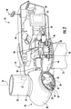
- Each rotor blade 22 may also include a pitch adjustment mechanism 32 configured to rotate each rotor blade 22 about its pitch axis 34.
- each pitch adjustment mechanism 32 may include a pitch drive motor 33 (e.g., any suitable electric, hydraulic, or pneumatic motor), a pitch drive gearbox 35, and a pitch drive pinion 37.
- the pitch drive motor 33 may be coupled to the pitch drive gearbox 35 so that the pitch drive motor 33 imparts mechanical force to the pitch drive gearbox 35.
- the pitch drive gearbox 35 may be coupled to the pitch drive pinion 37 for rotation therewith.
- the pitch drive pinion 37 may, in turn, be in rotational engagement with a pitch bearing 54 coupled between the hub 20 and a corresponding rotor blade 22 such that rotation of the pitch drive pinion 37 causes rotation of the pitch bearing 54.
- rotation of the pitch drive motor 33 drives the pitch drive gearbox 35 and the pitch drive pinion 37, thereby rotating the pitch bearing 54 and the rotor blade 22 about the pitch axis 34.
- the wind turbine 10 may include one or more yaw drive mechanisms 38 communicatively coupled to the controller 26, with each yaw drive mechanism(s) 38 being configured to change the angle of the nacelle 16 relative to the wind (e.g., by engaging a yaw bearing 56 of the wind turbine 10).
- the turbine controller 26 may also be communicatively coupled to each pitch adjustment mechanism 32 of the wind turbine 10 (one of which is shown) through a separate or integral pitch controller 30 ( FIG. 1 ) for controlling and/or altering the pitch angle of the rotor blades 22 (i.e., an angle that determines a perspective of the rotor blades 22 with respect to the direction 28 of the wind).
- one or more sensors 57, 58, 59 may be provided on the wind turbine 10. More specifically, as shown, a blade sensor 57 may be configured with one or more of the rotor blades 22 to monitor the rotor blades 22. Further, as shown, a wind sensor 58 may be provided on the wind turbine 10. For example, the wind sensor 58 may a wind vane, and anemometer, a LIDAR sensor, or another suitable sensor that measures wind speed and/or direction. In addition, a pitch sensor 59 may be configured with each of the pitch drive mechanism 32, e.g. with one or more batteries of the pitch drive motors 33 thereof, which will be discussed in more detail below.
- the sensors 57, 58, 59 may further be in communication with the controller 26, and may provide related information to the controller 26.
- the pitch sensor(s) 59 may correspond to temperature sensors that send temperature signals to the controllers 26, 30 to indicate a temperature of the pitch batteries, which is described in more detail herein.
- the term "monitor" and variations thereof indicates that the various sensors of the wind turbine 10 may be configured to provide a direct measurement of the parameters being monitored and/or an indirect measurement of such parameters.
- the sensors described herein may, for example, be used to generate signals relating to the parameter being monitored, which can then be utilized by the controller 26 to determine the condition.
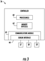
- the controller 26, 30 may include one or more processor(s) 60 and associated memory device(s) 62 configured to perform a variety of computer-implemented functions (e.g., performing the methods, steps, calculations and the like and storing relevant data as disclosed herein). Additionally, the controller 26, 30 may also include a communications module 64 to facilitate communications between the controller 26, 30 and the various components of the wind turbine 10.
- the communications module 64 may include a sensor interface 66 (e.g., one or more analog-to-digital converters) to permit signals transmitted from one or more sensors 57, 58, 59 to be converted into signals that can be understood and processed by the processors 60.
- the sensors 57, 58, 59 may be communicatively coupled to the communications module 64 using any suitable means.
- the sensors 57, 58, 59 are coupled to the sensor interface 66 via a wired connection.
- the sensors 57, 58, 59 may be coupled to the sensor interface 66 via a wireless connection, such as by using any suitable wireless communications protocol known in the art.
- the term "processor” refers not only to integrated circuits referred to in the art as being included in a computer, but also refers to a controller, a microcontroller, a microcomputer, a programmable logic controller (PLC), an application specific integrated circuit, and other programmable circuits.
- the memory device(s) 62 may generally comprise memory element(s) including, but not limited to, computer readable medium (e.g., random access memory (RAM)), computer readable non-volatile medium (e.g., a flash memory), a floppy disk, a compact disc-read only memory (CD-ROM), a magneto-optical disk (MOD), a digital versatile disc (DVD) and/or other suitable memory elements.
- RAM random access memory
- CD-ROM compact disc-read only memory
- MOD magneto-optical disk
- DVD digital versatile disc
- Such memory device(s) 62 may generally be configured to store suitable computer-readable instructions that, when implemented by the processor(s) 60, configure the controller 26 to perform various functions including, but not limited to, transmitting suitable control signals to implement corrective action(s) in response to a distance signal exceeding a predetermined threshold as described herein, as well as various other suitable computer-implemented functions.
- the pitch system 70 may include a plurality of pitch drive mechanisms 32, i.e. one for each pitch axis 34 so as to rotate respective pitch bearings 54. Further, as shown, each of the pitch drive mechanisms may be communicatively coupled to the power grid 45 as well as one or more backup batteries 72. More specifically, as shown, each pitch drive mechanism 32 may include a plurality of backup batteries 72 stored in a battery cabinet 74. During normal operation of the wind turbine 10, the pitch drive motors 33 are driven by the power grid 45. However, in some instances, such as during an adverse grid event or grid loss, the pitch drive motors 33 may be driven by one or more backup batteries 72.
- the control circuit 80 includes the pitch drive motor 33, a converter 82 for driving the motor 33, and the pitch controller 30 for controlling the circuit 80.
- the pitch drive motor 33 is a compound direct-current (DC) motor that includes an armature 86 and a shunt field winding 84 or coil.
- the pitch controller 30 may receive one or more control signals from the turbine controller 26 and operate the pitch drive motor(s) 33 accordingly.
- the shunt field winding 84 is generally the most temperature sensitive part in the motor.
- the control circuit 80 typically includes a temperature sensor 59 in or near the shunt field winding 84 so as to monitor the temperature thereof.
- the pitch controller 30 senses a temperature of the motor 33 (i.e. the shunt field winding 84) using the temperature sensor 59.
- the pitch controller 30 is configured to trip when the sensed temperature exceeds a predetermined threshold that is indicative of an over-temperature condition.
- the temperature sensor 59 may be a resistance temperature device (RTD). If the temperature sensor 59 fails, which can be a common failure mode, the pitch controller 30 also trips due to sensing an abnormal motor temperature, eventually causing the wind turbine 10 to shut down.
- RTD resistance temperature device
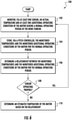
- the present disclosure is directed to systems and methods for predicting the motor temperature by learning the relationship between the shunt field resistance and its temperature when the temperature sensor 59 is working properly and using the temperature prediction when the temperature sensor 59 fails so as to reduce turbine down time. More specifically, as shown in FIG. 6 , a flow diagram of one embodiment of a method 100 for estimating the temperature of a motor 33 of the pitch drive mechanism 32 of one of the rotor blades 22 of the wind turbine 10 is illustrated. As shown at 102, the method 100 monitoring an actual temperature of the motor 33 via the temperature sensor 59 and at least one additional operating condition of the motor 33 during a normal operating period of the wind turbine 10.
- the actual temperature of the motor 33 is representative of the temperature of the shunt field temperature of the shunt field winding 84 of the motor 33.
- the additional operating condition(s) of the motor 33 may include a shunt field resistance, a shunt field current, a shunt field voltage, an armature current, an armature voltage, a motor speed, or similar, and/or combinations thereof.
- the method 100 includes storing, via the pitch controller 30, the monitored temperatures and the monitored additional operating conditions of the motor 33 for the normal operating period. As shown at 106, the method 100 includes determining a relationship between the monitored temperatures and the monitored additional operating conditions of the motor 33 for the normal operating period. More specifically, in certain embodiments, the pitch controller 30 may perform a statistical analysis on the monitored temperatures and the monitored resistances of the motor 33 for the normal operating period. For example, in one embodiment, the statistical analysis may include a regression analysis. Alternatively, it should be understood that any further statistical analysis may also be performed on the monitored temperatures and the monitored resistances of the motor 33 for the normal operating period.
- the pitch controller 30 may determine the relationship between the monitored temperatures and the monitored additional operating conditions of the motor 33 for the normal operating period via machine learning. Further, the pitch controller 30 may determine the relationship between the monitored temperatures and the monitored additional operating conditions of the motor for the normal operating period for multiple power cycles until a predetermined temperature rise of the motor is reached. More specifically, in certain embodiments, the predetermined temperature rise may include from about twenty (20) degrees to about sixty (60) degrees, such as about fifty (50) degrees.
- the pitch controller 30 may also be configured to generate a transfer function between the monitored temperatures and the monitored additional operating conditions of the motor 33 for the normal operating period. In such embodiments, the controller 30 is further configured to determine the estimated temperature of the motor 33 based on the transfer function, e.g. if the sensor 59 fails. In additional embodiments, the pitch controller 30 may also update the transfer function during the normal operating period of the wind turbine 10.
- the pitch controller 30 determines whether the temperature sensor 59 is operating properly. Accordingly, as shown at 110, in the event that the sensor fails to operate 59, the pitch controller 30 is configured to determine an estimated temperature of the motor 33 based on the relationship described above. For example, in one embodiment, the estimated temperature of the motor 33 may each represent an estimated temperature of the shunt field winding 84 of the motor 33. As described herein, the sensor failing to operate may be caused by a fault or short, an open switch, or any other sensor issue to cause the sensor 59 to not function or operate properly. In one embodiment, the pitch controller 30 may generate an alarm signal in the event that the temperature sensor 59 fails to operate.
- the method 200 starts.
- the method 200 includes initially storing a transfer function in a pitch controller of the pitch drive mechanism relating at least one actual temperature of the motor with at least one operating conditions of the motor for a normal operating period.
- the method 200 includes determining whether the sensor is operating properly or not. In the event that the temperature sensor 59 fails to operate, as shown at 208, the method 200 includes determining, via the pitch controller 30, an estimated temperature of the motor 33 based on the transfer function.
- the method 200 further includes comparing the estimated temperature with a present temperature limit of the motor and determining an accuracy of the transfer function based on the comparison. In another embodiment, the method 200 may further include updating the transfer function if the accuracy is above a predetermined threshold or generating an alarm signal if the accuracy is below a predetermined threshold.
Landscapes
- Engineering & Computer Science (AREA)
- Physics & Mathematics (AREA)
- General Physics & Mathematics (AREA)
- Sustainable Energy (AREA)
- Life Sciences & Earth Sciences (AREA)
- Sustainable Development (AREA)
- Chemical & Material Sciences (AREA)
- Combustion & Propulsion (AREA)
- Mechanical Engineering (AREA)
- General Engineering & Computer Science (AREA)
- Fluid Mechanics (AREA)
- Business, Economics & Management (AREA)
- Emergency Management (AREA)
- Computer Security & Cryptography (AREA)
- Wind Motors (AREA)
Claims (15)
- Verfahren zum Abschätzen einer Temperatur eines Motors (33) einer Pitch-Antriebsanordnung (32) eines Rotorblatts (22) einer Windkraftanlage (10), wobei das Verfahren Folgendes umfasst:Überwachen, mittels mindestens eines Sensors (59), einer tatsächlichen Temperatur und mindestens einer zusätzlichen Betriebsbedingung des Motors (33) während einer normalen Betriebsperiode der Windkraftanlage (10);Speichern der überwachten Temperaturen und der überwachten zusätzlichen Betriebsbedingungen des Motors (33) mittels einer Pitch-Steuerung (30) für die normale Betriebsperiode;Bestimmen einer Relation zwischen den überwachten Temperaturen und den überwachten zusätzlichen Betriebsbedingungen des Motors (33) für die normale Betriebsperiode; und,für den Fall, dass der Sensor (59) nicht funktioniert, Bestimmen einer geschätzten Temperatur des Motors (33) mittels der Pitch-Steuerung (30) basierend auf der Relation.
- Verfahren nach Anspruch 1, wobei die tatsächliche Temperatur und die geschätzte Temperatur des Motors (33) jeweils eine Nebenschlussfeldtemperatur einer Nebenschlussfeldwicklung (84) des Motors (33) darstellen.
- Verfahren nach Anspruch 1 oder 2, wobei die mindestens eine zusätzliche Betriebsbedingung des Motors (33) mindestens einen Nebenschlussfeldwiderstand, einen Nebenschlussfeldstrom, eine Nebenschlussfeldspannung, einen Ankerstrom, eine Ankerspannung, eine Drehzahl des Motors (33) oder Kombinationen davon umfasst.
- Verfahren nach Anspruch 1, 2 oder 3, wobei das Bestimmen der Relation zwischen den überwachten Temperaturen und den überwachten Widerständen des Motors (33) für die normale Betriebsperiode ferner umfasst:Durchführen einer statistischen Analyse der überwachten Temperaturen und der überwachten Widerstände des Motors (33) für die normale Betriebsperiode mittels der Pitch-Steuerung (30).
- Verfahren nach Anspruch 4, wobei die statistische Analyse eine Regressionsanalyse umfasst.
- Verfahren nach einem der vorhergehenden Ansprüche, wobei das Bestimmen der Relation zwischen den überwachten Temperaturen und den überwachten zusätzlichen Betriebsbedingungen des Motors (33) für die normale Betriebsperiode ferner aufweist:Bestimmen, mittels maschinellem Lernen, der Relation zwischen den überwachten Temperaturen und den überwachten zusätzlichen Betriebsbedingungen des Motors (33) für den normalen Betriebszeitraum für mehrere Leistungszyklen, bis ein vorbestimmter Temperaturanstieg des Motors (33) erreicht ist.
- Verfahren nach Anspruch 6, wobei der vorbestimmte Temperaturanstieg von etwa zwanzig (20) Grad bis etwa sechzig (60) Grad aufweisend ist.
- Verfahren nach einem der vorhergehenden Ansprüche, ferner umfassend:Erzeugen einer Übertragungsfunktion zwischen den überwachten Temperaturen und den überwachten zusätzlichen Betriebsbedingungen des Motors (33) für die normale Betriebsperiode; und
Bestimmen, mittels der Pitch-Steuerung (30), der geschätzten Temperatur des Motors (33) basierend auf der Übertragungsfunktion, wenn der Sensor (59) ausfällt. - Verfahren nach Anspruch 8, ferner aufweisend das Aktualisieren der Übertragungsfunktion während des normalen Betriebszeitraums der Windkraftanlage (10).
- Verfahren nach einem der vorhergehenden Ansprüche, wobei der Ausfall des Sensors (59) durch mindestens einen Fehler oder einen geöffneten Schalter verursacht wird.
- Verfahren nach einem der vorhergehenden Ansprüche weist ferner auf, dass mittels der Pitch-Steuerung (30) für den Fall, dass der Sensor (59) nicht funktioniert, ein Alarmsignal erzeugt wird.
- Pitch-System (70) für eine Windkraftanlage (10), wobei das Pitch-System (70) umfasst:einen Pitch-Antriebsmotor (33), der einen Anker (86) und eine Nebenschlussfeldwicklung (84) aufweist;mindestens einen Sensor (59), der derart konfiguriert ist, dass er eine tatsächliche Temperatur und mindestens eine zusätzliche Betriebsbedingung der Nebenschlussfeldwicklung (84) während einer normalen Betriebsperiode der Windkraftanlage (10) überwacht;einen Umrichter (82), der kommunikativ mit dem Pitch-Tauchmotor (33) verbunden ist, um den Anker anzutreiben; und,eine Pitch-Steuerung (30), die kommunikativ mit dem mindestens einen Sensor (59) verbunden ist, wobei die Pitch-Steuerung (30) mindestens einen Prozessor aufweist, der derart konfiguriert ist, dass er eine oder mehrere Operationen durchführt, wobei die eine oder die mehreren Operationen Folgendes umfassen:Speichern der überwachten Temperaturen und der überwachten zusätzlichen Betriebsbedingungen des Motors (33) für die normale Betriebsperiode;Bestimmen einer Relation zwischen den überwachten Temperaturen und den überwachten zusätzlichen Betriebsbedingungen des Motors (33) für die normale Betriebsperiode; und,für den Fall, dass der Sensor (59) nicht funktioniert, Bestimmen einer geschätzten Temperatur des Motors (33) basierend auf der Relation.
- System (70) nach Anspruch 12, wobei der mindestens eine Sensor (59) einen Widerstandstemperaturdetektor (RTD) umfasst.
- System (70) nach Anspruch 12 oder 13, wobei die tatsächliche Temperatur und die geschätzte Temperatur des Motors (33) jeweils eine Nebenschlussfeldtemperatur einer Nebenschlussfeldwicklung (84) des Motors (33) darstellen.
- System (70) nach Anspruch 12, 13 oder 14, wobei die mindestens eine zusätzliche Betriebsbedingung des Motors (33) mindestens einen Nebenschlussfeldwiderstand, einen Nebenschlussfeldstrom, eine Nebenschlussfeldspannung, einen Ankerstrom, eine Ankerspannung, eine Drehzahl des Motors (33) oder Kombinationen davon umfassen.
Applications Claiming Priority (1)
| Application Number | Priority Date | Filing Date | Title |
|---|---|---|---|
| PCT/CN2017/084941 WO2018209655A1 (en) | 2017-05-18 | 2017-05-18 | System and method for estimating motor temperature of a pitch system of a wind turbine |
Publications (3)
| Publication Number | Publication Date |
|---|---|
| EP3625528A1 EP3625528A1 (de) | 2020-03-25 |
| EP3625528A4 EP3625528A4 (de) | 2021-01-13 |
| EP3625528B1 true EP3625528B1 (de) | 2022-03-09 |
Family
ID=64273198
Family Applications (1)
| Application Number | Title | Priority Date | Filing Date |
|---|---|---|---|
| EP17910282.7A Active EP3625528B1 (de) | 2017-05-18 | 2017-05-18 | System und verfahren zur schätzung der motortemperatur eines winkelverstellsystems einer windturbine |
Country Status (5)
| Country | Link |
|---|---|
| US (1) | US11629701B2 (de) |
| EP (1) | EP3625528B1 (de) |
| DK (1) | DK3625528T3 (de) |
| ES (1) | ES2917417T3 (de) |
| WO (1) | WO2018209655A1 (de) |
Families Citing this family (6)
| Publication number | Priority date | Publication date | Assignee | Title |
|---|---|---|---|---|
| CN113446156B (zh) * | 2020-03-27 | 2023-07-11 | 新疆金风科技股份有限公司 | 变桨系统的状态监测方法、装置、设备及介质 |
| ES3038176T3 (en) * | 2020-06-04 | 2025-10-09 | Vestas Wind Sys As | Temperature estimation in a wind turbine |
| US12117783B2 (en) * | 2020-10-15 | 2024-10-15 | Abb Schweiz Ag | Online frequently derived measurements for process monitoring, control and optimization |
| CN114235415B (zh) * | 2022-02-28 | 2022-06-03 | 浙江大学 | 基于神经网络的风力发电机变桨轴承故障诊断方法及装置 |
| CN117329072A (zh) * | 2022-06-23 | 2024-01-02 | 北京金风科创风电设备有限公司 | 风力发电机组的变桨控制方法、控制器和风力发电机组 |
| CN118793569B (zh) * | 2023-04-14 | 2026-03-17 | 北京金风科创风电设备有限公司 | 变桨系统的异常检测方法及装置 |
Family Cites Families (23)
| Publication number | Priority date | Publication date | Assignee | Title |
|---|---|---|---|---|
| US20040119470A1 (en) | 2002-09-13 | 2004-06-24 | Sankyo Seiki Mfg. Co., Ltd. | Winding type magnetic sensor device and coin discriminating sensor device |
| JP4501433B2 (ja) | 2003-10-24 | 2010-07-14 | ダイキン工業株式会社 | Dcモータのコイル温度推定方法およびその装置 |
| CN2874580Y (zh) | 2006-03-01 | 2007-02-28 | 元山科技工业股份有限公司 | 直流无刷风扇马达的温控变速电路 |
| DE102006029640B4 (de) | 2006-06-28 | 2010-01-14 | Nordex Energy Gmbh | Windenergieanlage mit einem Maschinenhaus |
| EP2232697A1 (de) * | 2007-12-14 | 2010-09-29 | Vestas Wind Systems A/S | Lebensdaueroptimierung eines windturbinengenerators durch steuerung der generatortemperatur |
| CN102549910B (zh) | 2009-09-29 | 2016-05-25 | 胡斯华纳有限公司 | 电动机及用于控制该电动机的方法 |
| CN102312772B (zh) | 2010-06-29 | 2013-06-26 | 上海派恩科技有限公司 | 一种风力发电机变桨距系统控制方法 |
| DE102010036358A1 (de) * | 2010-07-12 | 2012-01-12 | Ssb Wind Systems Gmbh & Co. Kg | Blattwinkelverstellantrieb für eine Windkraftanlage |
| CN103154509B (zh) | 2010-08-23 | 2016-03-16 | 维斯塔斯风力系统集团公司 | 运行风力涡轮机的方法和风力涡轮机 |
| JP5397785B2 (ja) | 2011-08-01 | 2014-01-22 | 株式会社デンソー | 3相回転機の制御装置 |
| CN102330645A (zh) | 2011-09-19 | 2012-01-25 | 吴建华 | 一种风电机组结构健康监测系统及其方法 |
| CN102721924B (zh) | 2012-06-26 | 2014-07-02 | 新疆金风科技股份有限公司 | 风力发电机组的故障预警方法 |
| JP3180372U (ja) | 2012-10-04 | 2012-12-13 | 永興電機工業株式会社 | パワーユニット・モニタ機構 |
| JP5607698B2 (ja) | 2012-10-18 | 2014-10-15 | ファナック株式会社 | 電動機の温度を推定する温度推定装置 |
| JP2014107956A (ja) | 2012-11-28 | 2014-06-09 | Hitachi Automotive Systems Ltd | モータ、制御装置およびモータ駆動装置 |
| CN104283483B (zh) | 2013-07-02 | 2018-07-24 | 韩华兰德系统株式会社 | 用于控制电机的系统和方法 |
| CN103758696B (zh) | 2014-01-09 | 2016-05-25 | 华北电力大学 | 基于scada温度参数的风电机组安全状况评价方法 |
| JP6080894B2 (ja) | 2015-05-14 | 2017-02-15 | Ntn株式会社 | 電動モータ装置および電動式直動アクチュエータ |
| WO2016206692A1 (en) * | 2015-06-24 | 2016-12-29 | Vestas Wind Systems A/S | Blade load sensing system for a wind turbine |
| CN105134510A (zh) | 2015-09-18 | 2015-12-09 | 北京中恒博瑞数字电力科技有限公司 | 一种风力发电机组变桨系统的状态监测和故障诊断方法 |
| JP6361641B2 (ja) * | 2015-12-03 | 2018-07-25 | 横河電機株式会社 | フィールド機器 |
| US11062588B2 (en) * | 2016-03-23 | 2021-07-13 | Solaredge Technologies Ltd. | Conductor temperature detector |
| CN106050562B (zh) | 2016-07-21 | 2019-09-10 | 江阴弘远新能源科技有限公司 | 一种风力发电变桨控制系统 |
-
2017
- 2017-05-18 ES ES17910282T patent/ES2917417T3/es active Active
- 2017-05-18 EP EP17910282.7A patent/EP3625528B1/de active Active
- 2017-05-18 WO PCT/CN2017/084941 patent/WO2018209655A1/en not_active Ceased
- 2017-05-18 US US16/614,530 patent/US11629701B2/en active Active
- 2017-05-18 DK DK17910282.7T patent/DK3625528T3/da active
Also Published As
| Publication number | Publication date |
|---|---|
| DK3625528T3 (da) | 2022-06-13 |
| ES2917417T3 (es) | 2022-07-08 |
| EP3625528A1 (de) | 2020-03-25 |
| US11629701B2 (en) | 2023-04-18 |
| EP3625528A4 (de) | 2021-01-13 |
| WO2018209655A1 (en) | 2018-11-22 |
| US20200109700A1 (en) | 2020-04-09 |
Similar Documents
| Publication | Publication Date | Title |
|---|---|---|
| US11629701B2 (en) | System and method for estimating motor temperature of a pitch system of a wind turbine | |
| EP3409940B1 (de) | Verfahren zur reduzierung von lasten während eines leerlaufs oder im geparkten zustand einer windturbine über gier-versatz | |
| EP3597905B1 (de) | System und verfahren zur erkennung eines neigungsfehlers in einer windturbine mittels spannungs-, strom-, drehmoment- oder kraftüberwachung | |
| JP6247957B2 (ja) | 風力発電装置のヨー制御システム及びヨー制御方法 | |
| EP3597904B1 (de) | System und verfahren zur reduzierung der belastungen von windturbinen durch gieren der gondel in eine vorbestimmte position basierend auf dem rotorungleichgewicht | |
| EP3543523B1 (de) | System und verfahren zum testen einer energiespeichervorrichtung eines windturbinenneigungswinkelsystems | |
| CN101900081B (zh) | 在电动机超温条件下操作的风力涡轮机及其操作方法 | |
| EP3581795B1 (de) | System und verfahren zur steuerung einer windturbine zur minimierung von rotorblattschäden | |
| EP3470669B1 (de) | Verfahren zur minderung von blattausreisserlasten bei einem neigungssystemausfall | |
| EP3454067B1 (de) | Systeme und verfahren zur prädiktiven batterieprüfung | |
| EP3597910B1 (de) | System und verfahren zur reduzierung von lasten während eines leerlaufs oder im geparkten zustand einer windturbine mit einem festgefahrenen rotorblatt | |
| EP3029318B1 (de) | System und verfahren zur steuerung einer windturbine während ungünstiger windverhältnisse | |
| US10738767B2 (en) | System and method for estimating consumed battery life of a pitch system of a wind turbine | |
| EP3722596B1 (de) | System und verfahren zur minderung von schäden in einem rotorblatt einer windturbine | |
| EP4325047B1 (de) | Lastabhängige autonome giersteuerung für eine windturbine | |
| EP3722597B1 (de) | System und verfahren zur verhinderung von katastrophalen schäden im antriebsstrang einer windturbine | |
| CN113446156A (zh) | 变桨系统的状态监测方法、装置、设备及介质 | |
| EP3597906B1 (de) | System und verfahren zur reduzierung der belastungen einer windturbine, wenn ein rotorblatt festsitzt |
Legal Events
| Date | Code | Title | Description |
|---|---|---|---|
| STAA | Information on the status of an ep patent application or granted ep patent |
Free format text: STATUS: THE INTERNATIONAL PUBLICATION HAS BEEN MADE |
|
| PUAI | Public reference made under article 153(3) epc to a published international application that has entered the european phase |
Free format text: ORIGINAL CODE: 0009012 |
|
| STAA | Information on the status of an ep patent application or granted ep patent |
Free format text: STATUS: REQUEST FOR EXAMINATION WAS MADE |
|
| 17P | Request for examination filed |
Effective date: 20191213 |
|
| AK | Designated contracting states |
Kind code of ref document: A1 Designated state(s): AL AT BE BG CH CY CZ DE DK EE ES FI FR GB GR HR HU IE IS IT LI LT LU LV MC MK MT NL NO PL PT RO RS SE SI SK SM TR |
|
| AX | Request for extension of the european patent |
Extension state: BA ME |
|
| DAV | Request for validation of the european patent (deleted) | ||
| DAX | Request for extension of the european patent (deleted) | ||
| A4 | Supplementary search report drawn up and despatched |
Effective date: 20201215 |
|
| RIC1 | Information provided on ipc code assigned before grant |
Ipc: G01K 7/16 20060101AFI20201209BHEP Ipc: F03D 7/02 20060101ALI20201209BHEP |
|
| GRAP | Despatch of communication of intention to grant a patent |
Free format text: ORIGINAL CODE: EPIDOSNIGR1 |
|
| STAA | Information on the status of an ep patent application or granted ep patent |
Free format text: STATUS: GRANT OF PATENT IS INTENDED |
|
| GRAJ | Information related to disapproval of communication of intention to grant by the applicant or resumption of examination proceedings by the epo deleted |
Free format text: ORIGINAL CODE: EPIDOSDIGR1 |
|
| STAA | Information on the status of an ep patent application or granted ep patent |
Free format text: STATUS: REQUEST FOR EXAMINATION WAS MADE |
|
| GRAP | Despatch of communication of intention to grant a patent |
Free format text: ORIGINAL CODE: EPIDOSNIGR1 |
|
| STAA | Information on the status of an ep patent application or granted ep patent |
Free format text: STATUS: GRANT OF PATENT IS INTENDED |
|
| INTG | Intention to grant announced |
Effective date: 20211013 |
|
| INTC | Intention to grant announced (deleted) | ||
| INTG | Intention to grant announced |
Effective date: 20211026 |
|
| GRAS | Grant fee paid |
Free format text: ORIGINAL CODE: EPIDOSNIGR3 |
|
| GRAA | (expected) grant |
Free format text: ORIGINAL CODE: 0009210 |
|
| STAA | Information on the status of an ep patent application or granted ep patent |
Free format text: STATUS: THE PATENT HAS BEEN GRANTED |
|
| AK | Designated contracting states |
Kind code of ref document: B1 Designated state(s): AL AT BE BG CH CY CZ DE DK EE ES FI FR GB GR HR HU IE IS IT LI LT LU LV MC MK MT NL NO PL PT RO RS SE SI SK SM TR |
|
| REG | Reference to a national code |
Ref country code: CH Ref legal event code: EP Ref country code: AT Ref legal event code: REF Ref document number: 1474540 Country of ref document: AT Kind code of ref document: T Effective date: 20220315 |
|
| REG | Reference to a national code |
Ref country code: DE Ref legal event code: R096 Ref document number: 602017054533 Country of ref document: DE |
|
| REG | Reference to a national code |
Ref country code: IE Ref legal event code: FG4D |
|
| REG | Reference to a national code |
Ref country code: DK Ref legal event code: T3 Effective date: 20220610 |
|
| REG | Reference to a national code |
Ref country code: LT Ref legal event code: MG9D |
|
| REG | Reference to a national code |
Ref country code: ES Ref legal event code: FG2A Ref document number: 2917417 Country of ref document: ES Kind code of ref document: T3 Effective date: 20220708 |
|
| REG | Reference to a national code |
Ref country code: NL Ref legal event code: MP Effective date: 20220309 |
|
| PG25 | Lapsed in a contracting state [announced via postgrant information from national office to epo] |
Ref country code: SE Free format text: LAPSE BECAUSE OF FAILURE TO SUBMIT A TRANSLATION OF THE DESCRIPTION OR TO PAY THE FEE WITHIN THE PRESCRIBED TIME-LIMIT Effective date: 20220309 Ref country code: RS Free format text: LAPSE BECAUSE OF FAILURE TO SUBMIT A TRANSLATION OF THE DESCRIPTION OR TO PAY THE FEE WITHIN THE PRESCRIBED TIME-LIMIT Effective date: 20220309 Ref country code: NO Free format text: LAPSE BECAUSE OF FAILURE TO SUBMIT A TRANSLATION OF THE DESCRIPTION OR TO PAY THE FEE WITHIN THE PRESCRIBED TIME-LIMIT Effective date: 20220609 Ref country code: LT Free format text: LAPSE BECAUSE OF FAILURE TO SUBMIT A TRANSLATION OF THE DESCRIPTION OR TO PAY THE FEE WITHIN THE PRESCRIBED TIME-LIMIT Effective date: 20220309 Ref country code: HR Free format text: LAPSE BECAUSE OF FAILURE TO SUBMIT A TRANSLATION OF THE DESCRIPTION OR TO PAY THE FEE WITHIN THE PRESCRIBED TIME-LIMIT Effective date: 20220309 Ref country code: BG Free format text: LAPSE BECAUSE OF FAILURE TO SUBMIT A TRANSLATION OF THE DESCRIPTION OR TO PAY THE FEE WITHIN THE PRESCRIBED TIME-LIMIT Effective date: 20220609 |
|
| REG | Reference to a national code |
Ref country code: AT Ref legal event code: MK05 Ref document number: 1474540 Country of ref document: AT Kind code of ref document: T Effective date: 20220309 |
|
| PG25 | Lapsed in a contracting state [announced via postgrant information from national office to epo] |
Ref country code: LV Free format text: LAPSE BECAUSE OF FAILURE TO SUBMIT A TRANSLATION OF THE DESCRIPTION OR TO PAY THE FEE WITHIN THE PRESCRIBED TIME-LIMIT Effective date: 20220309 Ref country code: GR Free format text: LAPSE BECAUSE OF FAILURE TO SUBMIT A TRANSLATION OF THE DESCRIPTION OR TO PAY THE FEE WITHIN THE PRESCRIBED TIME-LIMIT Effective date: 20220610 Ref country code: FI Free format text: LAPSE BECAUSE OF FAILURE TO SUBMIT A TRANSLATION OF THE DESCRIPTION OR TO PAY THE FEE WITHIN THE PRESCRIBED TIME-LIMIT Effective date: 20220309 |
|
| PG25 | Lapsed in a contracting state [announced via postgrant information from national office to epo] |
Ref country code: NL Free format text: LAPSE BECAUSE OF FAILURE TO SUBMIT A TRANSLATION OF THE DESCRIPTION OR TO PAY THE FEE WITHIN THE PRESCRIBED TIME-LIMIT Effective date: 20220309 |
|
| PG25 | Lapsed in a contracting state [announced via postgrant information from national office to epo] |
Ref country code: SM Free format text: LAPSE BECAUSE OF FAILURE TO SUBMIT A TRANSLATION OF THE DESCRIPTION OR TO PAY THE FEE WITHIN THE PRESCRIBED TIME-LIMIT Effective date: 20220309 Ref country code: SK Free format text: LAPSE BECAUSE OF FAILURE TO SUBMIT A TRANSLATION OF THE DESCRIPTION OR TO PAY THE FEE WITHIN THE PRESCRIBED TIME-LIMIT Effective date: 20220309 Ref country code: RO Free format text: LAPSE BECAUSE OF FAILURE TO SUBMIT A TRANSLATION OF THE DESCRIPTION OR TO PAY THE FEE WITHIN THE PRESCRIBED TIME-LIMIT Effective date: 20220309 Ref country code: PT Free format text: LAPSE BECAUSE OF FAILURE TO SUBMIT A TRANSLATION OF THE DESCRIPTION OR TO PAY THE FEE WITHIN THE PRESCRIBED TIME-LIMIT Effective date: 20220711 Ref country code: EE Free format text: LAPSE BECAUSE OF FAILURE TO SUBMIT A TRANSLATION OF THE DESCRIPTION OR TO PAY THE FEE WITHIN THE PRESCRIBED TIME-LIMIT Effective date: 20220309 Ref country code: CZ Free format text: LAPSE BECAUSE OF FAILURE TO SUBMIT A TRANSLATION OF THE DESCRIPTION OR TO PAY THE FEE WITHIN THE PRESCRIBED TIME-LIMIT Effective date: 20220309 Ref country code: AT Free format text: LAPSE BECAUSE OF FAILURE TO SUBMIT A TRANSLATION OF THE DESCRIPTION OR TO PAY THE FEE WITHIN THE PRESCRIBED TIME-LIMIT Effective date: 20220309 |
|
| PG25 | Lapsed in a contracting state [announced via postgrant information from national office to epo] |
Ref country code: PL Free format text: LAPSE BECAUSE OF FAILURE TO SUBMIT A TRANSLATION OF THE DESCRIPTION OR TO PAY THE FEE WITHIN THE PRESCRIBED TIME-LIMIT Effective date: 20220309 Ref country code: IS Free format text: LAPSE BECAUSE OF FAILURE TO SUBMIT A TRANSLATION OF THE DESCRIPTION OR TO PAY THE FEE WITHIN THE PRESCRIBED TIME-LIMIT Effective date: 20220709 Ref country code: AL Free format text: LAPSE BECAUSE OF FAILURE TO SUBMIT A TRANSLATION OF THE DESCRIPTION OR TO PAY THE FEE WITHIN THE PRESCRIBED TIME-LIMIT Effective date: 20220309 |
|
| REG | Reference to a national code |
Ref country code: DE Ref legal event code: R097 Ref document number: 602017054533 Country of ref document: DE |
|
| REG | Reference to a national code |
Ref country code: CH Ref legal event code: PL |
|
| PLBE | No opposition filed within time limit |
Free format text: ORIGINAL CODE: 0009261 |
|
| STAA | Information on the status of an ep patent application or granted ep patent |
Free format text: STATUS: NO OPPOSITION FILED WITHIN TIME LIMIT |
|
| REG | Reference to a national code |
Ref country code: BE Ref legal event code: MM Effective date: 20220531 |
|
| PG25 | Lapsed in a contracting state [announced via postgrant information from national office to epo] |
Ref country code: MC Free format text: LAPSE BECAUSE OF FAILURE TO SUBMIT A TRANSLATION OF THE DESCRIPTION OR TO PAY THE FEE WITHIN THE PRESCRIBED TIME-LIMIT Effective date: 20220309 Ref country code: LU Free format text: LAPSE BECAUSE OF NON-PAYMENT OF DUE FEES Effective date: 20220518 Ref country code: LI Free format text: LAPSE BECAUSE OF NON-PAYMENT OF DUE FEES Effective date: 20220531 Ref country code: CH Free format text: LAPSE BECAUSE OF NON-PAYMENT OF DUE FEES Effective date: 20220531 |
|
| 26N | No opposition filed |
Effective date: 20221212 |
|
| PG25 | Lapsed in a contracting state [announced via postgrant information from national office to epo] |
Ref country code: SI Free format text: LAPSE BECAUSE OF FAILURE TO SUBMIT A TRANSLATION OF THE DESCRIPTION OR TO PAY THE FEE WITHIN THE PRESCRIBED TIME-LIMIT Effective date: 20220309 |
|
| GBPC | Gb: european patent ceased through non-payment of renewal fee |
Effective date: 20220609 |
|
| PG25 | Lapsed in a contracting state [announced via postgrant information from national office to epo] |
Ref country code: IE Free format text: LAPSE BECAUSE OF NON-PAYMENT OF DUE FEES Effective date: 20220518 Ref country code: FR Free format text: LAPSE BECAUSE OF NON-PAYMENT OF DUE FEES Effective date: 20220531 |
|
| PG25 | Lapsed in a contracting state [announced via postgrant information from national office to epo] |
Ref country code: GB Free format text: LAPSE BECAUSE OF NON-PAYMENT OF DUE FEES Effective date: 20220609 Ref country code: BE Free format text: LAPSE BECAUSE OF NON-PAYMENT OF DUE FEES Effective date: 20220531 |
|
| P01 | Opt-out of the competence of the unified patent court (upc) registered |
Effective date: 20230530 |
|
| PG25 | Lapsed in a contracting state [announced via postgrant information from national office to epo] |
Ref country code: IT Free format text: LAPSE BECAUSE OF FAILURE TO SUBMIT A TRANSLATION OF THE DESCRIPTION OR TO PAY THE FEE WITHIN THE PRESCRIBED TIME-LIMIT Effective date: 20220309 |
|
| REG | Reference to a national code |
Ref country code: DE Ref legal event code: R082 Ref document number: 602017054533 Country of ref document: DE Ref country code: DE Ref legal event code: R081 Ref document number: 602017054533 Country of ref document: DE Owner name: GENERAL ELECTRIC RENOVABLES ESPANA, S.L., ES Free format text: FORMER OWNER: GENERAL ELECTRIC COMPANY, SCHENECTADY, NY, US Ref country code: DE Ref legal event code: R082 Ref document number: 602017054533 Country of ref document: DE Representative=s name: ZIMMERMANN & PARTNER PATENTANWAELTE MBB, DE |
|
| REG | Reference to a national code |
Ref country code: DE Ref legal event code: R082 Ref document number: 602017054533 Country of ref document: DE Representative=s name: ZIMMERMANN & PARTNER PATENTANWAELTE MBB, DE |
|
| PG25 | Lapsed in a contracting state [announced via postgrant information from national office to epo] |
Ref country code: MK Free format text: LAPSE BECAUSE OF FAILURE TO SUBMIT A TRANSLATION OF THE DESCRIPTION OR TO PAY THE FEE WITHIN THE PRESCRIBED TIME-LIMIT Effective date: 20220309 Ref country code: CY Free format text: LAPSE BECAUSE OF FAILURE TO SUBMIT A TRANSLATION OF THE DESCRIPTION OR TO PAY THE FEE WITHIN THE PRESCRIBED TIME-LIMIT Effective date: 20220309 |
|
| PG25 | Lapsed in a contracting state [announced via postgrant information from national office to epo] |
Ref country code: HU Free format text: LAPSE BECAUSE OF FAILURE TO SUBMIT A TRANSLATION OF THE DESCRIPTION OR TO PAY THE FEE WITHIN THE PRESCRIBED TIME-LIMIT; INVALID AB INITIO Effective date: 20170518 |
|
| REG | Reference to a national code |
Ref country code: ES Ref legal event code: PC2A Owner name: GENERAL ELECTRIC RENOVABLES ESPANA S.L. Effective date: 20240809 |
|
| PG25 | Lapsed in a contracting state [announced via postgrant information from national office to epo] |
Ref country code: MT Free format text: LAPSE BECAUSE OF FAILURE TO SUBMIT A TRANSLATION OF THE DESCRIPTION OR TO PAY THE FEE WITHIN THE PRESCRIBED TIME-LIMIT Effective date: 20220309 |
|
| PGFP | Annual fee paid to national office [announced via postgrant information from national office to epo] |
Ref country code: DE Payment date: 20250423 Year of fee payment: 9 |
|
| PGFP | Annual fee paid to national office [announced via postgrant information from national office to epo] |
Ref country code: ES Payment date: 20250602 Year of fee payment: 9 Ref country code: DK Payment date: 20250423 Year of fee payment: 9 |
|
| PG25 | Lapsed in a contracting state [announced via postgrant information from national office to epo] |
Ref country code: TR Free format text: LAPSE BECAUSE OF FAILURE TO SUBMIT A TRANSLATION OF THE DESCRIPTION OR TO PAY THE FEE WITHIN THE PRESCRIBED TIME-LIMIT Effective date: 20220309 |