EP3625728B1 - Procédé de génération d'un modèle biométrique 3d d'une partie corporelle d'un utilisateur et dispositif électronique associé - Google Patents
Procédé de génération d'un modèle biométrique 3d d'une partie corporelle d'un utilisateur et dispositif électronique associé Download PDFInfo
- Publication number
- EP3625728B1 EP3625728B1 EP18834583.9A EP18834583A EP3625728B1 EP 3625728 B1 EP3625728 B1 EP 3625728B1 EP 18834583 A EP18834583 A EP 18834583A EP 3625728 B1 EP3625728 B1 EP 3625728B1
- Authority
- EP
- European Patent Office
- Prior art keywords
- body part
- image
- electronic device
- user
- finger
- Prior art date
- Legal status (The legal status is an assumption and is not a legal conclusion. Google has not performed a legal analysis and makes no representation as to the accuracy of the status listed.)
- Active
Links
Images




Classifications
-
- G—PHYSICS
- G06—COMPUTING OR CALCULATING; COUNTING
- G06F—ELECTRIC DIGITAL DATA PROCESSING
- G06F21/00—Security arrangements for protecting computers, components thereof, programs or data against unauthorised activity
- G06F21/30—Authentication, i.e. establishing the identity or authorisation of security principals
- G06F21/31—User authentication
- G06F21/32—User authentication using biometric data, e.g. fingerprints, iris scans or voiceprints
-
- G—PHYSICS
- G06—COMPUTING OR CALCULATING; COUNTING
- G06T—IMAGE DATA PROCESSING OR GENERATION, IN GENERAL
- G06T17/00—Three-dimensional [3D] modelling for computer graphics
-
- G—PHYSICS
- G06—COMPUTING OR CALCULATING; COUNTING
- G06V—IMAGE OR VIDEO RECOGNITION OR UNDERSTANDING
- G06V10/00—Arrangements for image or video recognition or understanding
- G06V10/10—Image acquisition
- G06V10/12—Details of acquisition arrangements; Constructional details thereof
- G06V10/14—Optical characteristics of the device performing the acquisition or on the illumination arrangements
- G06V10/145—Illumination specially adapted for pattern recognition, e.g. using gratings
-
- G—PHYSICS
- G06—COMPUTING OR CALCULATING; COUNTING
- G06V—IMAGE OR VIDEO RECOGNITION OR UNDERSTANDING
- G06V20/00—Scenes; Scene-specific elements
- G06V20/60—Type of objects
- G06V20/64—Three-dimensional [3D] objects
-
- G—PHYSICS
- G06—COMPUTING OR CALCULATING; COUNTING
- G06V—IMAGE OR VIDEO RECOGNITION OR UNDERSTANDING
- G06V40/00—Recognition of biometric, human-related or animal-related patterns in image or video data
- G06V40/10—Human or animal bodies, e.g. vehicle occupants or pedestrians; Body parts, e.g. hands
- G06V40/107—Static hand or arm
-
- G—PHYSICS
- G06—COMPUTING OR CALCULATING; COUNTING
- G06V—IMAGE OR VIDEO RECOGNITION OR UNDERSTANDING
- G06V40/00—Recognition of biometric, human-related or animal-related patterns in image or video data
- G06V40/10—Human or animal bodies, e.g. vehicle occupants or pedestrians; Body parts, e.g. hands
- G06V40/12—Fingerprints or palmprints
- G06V40/13—Sensors therefor
- G06V40/1312—Sensors therefor direct reading, e.g. contactless acquisition
-
- G—PHYSICS
- G06—COMPUTING OR CALCULATING; COUNTING
- G06V—IMAGE OR VIDEO RECOGNITION OR UNDERSTANDING
- G06V40/00—Recognition of biometric, human-related or animal-related patterns in image or video data
- G06V40/10—Human or animal bodies, e.g. vehicle occupants or pedestrians; Body parts, e.g. hands
- G06V40/18—Eye characteristics, e.g. of the iris
- G06V40/19—Sensors therefor
-
- H—ELECTRICITY
- H04—ELECTRIC COMMUNICATION TECHNIQUE
- H04N—PICTORIAL COMMUNICATION, e.g. TELEVISION
- H04N23/00—Cameras or camera modules comprising electronic image sensors; Control thereof
- H04N23/56—Cameras or camera modules comprising electronic image sensors; Control thereof provided with illuminating means
-
- H—ELECTRICITY
- H04—ELECTRIC COMMUNICATION TECHNIQUE
- H04N—PICTORIAL COMMUNICATION, e.g. TELEVISION
- H04N23/00—Cameras or camera modules comprising electronic image sensors; Control thereof
- H04N23/60—Control of cameras or camera modules
-
- G—PHYSICS
- G03—PHOTOGRAPHY; CINEMATOGRAPHY; ANALOGOUS TECHNIQUES USING WAVES OTHER THAN OPTICAL WAVES; ELECTROGRAPHY; HOLOGRAPHY
- G03B—APPARATUS OR ARRANGEMENTS FOR TAKING PHOTOGRAPHS OR FOR PROJECTING OR VIEWING THEM; APPARATUS OR ARRANGEMENTS EMPLOYING ANALOGOUS TECHNIQUES USING WAVES OTHER THAN OPTICAL WAVES; ACCESSORIES THEREFOR
- G03B35/00—Stereoscopic photography
- G03B35/08—Stereoscopic photography by simultaneous recording
-
- G—PHYSICS
- G06—COMPUTING OR CALCULATING; COUNTING
- G06V—IMAGE OR VIDEO RECOGNITION OR UNDERSTANDING
- G06V40/00—Recognition of biometric, human-related or animal-related patterns in image or video data
- G06V40/10—Human or animal bodies, e.g. vehicle occupants or pedestrians; Body parts, e.g. hands
- G06V40/12—Fingerprints or palmprints
- G06V40/1341—Sensing with light passing through the finger
-
- G—PHYSICS
- G06—COMPUTING OR CALCULATING; COUNTING
- G06V—IMAGE OR VIDEO RECOGNITION OR UNDERSTANDING
- G06V40/00—Recognition of biometric, human-related or animal-related patterns in image or video data
- G06V40/10—Human or animal bodies, e.g. vehicle occupants or pedestrians; Body parts, e.g. hands
- G06V40/14—Vascular patterns
Definitions
- the disclosure relates to three-dimensional (3D) modeling using electronic devices. More particularly, the disclosure relates to an electronic device and method for generating a 3D biometric model of a body part of a user.
- biometric identification is widely used in various applications such as forensics, government agencies, banking and financial institutions, enterprise identity management, and other identification and recognition applications.
- Multiple technologies have been developed for biometric identification of individuals using physical features fingerprints, retinal, iris, voice, facial features, finger vein pattern, palm vein pattern, etc.
- a two-dimensional (2D) finger vein pattern is obtained by illuminating a finger with a light at a specific wavelength (e.g., near infrared) such that the light is absorbed by blood in the finger veins according to the related art.
- the scattered light is then detected by imaging sensors to produce a 2D image of the finger vein pattern where the finger-vein pattern appears as a 2D network of dark lines.
- a 2D model of the body part may not be able to capture all the information necessary for feature extraction due to low compatibility to illumination. Further, creating an imitation of the 2D model of the body part can be easily achieved, which makes the systems which use 2D biometrics susceptible to spoofing attacks.
- the three-dimensional (3D) models of the body parts used for biometric identification capture more information necessary for feature extraction and hence are difficult to be imitated.
- the equipment that is used for generating the 3D models of the body parts are bulky and expensive.
- US2016/071111 describes an authentication process that prompts the user to perform an action in view of a camera or sensor.
- US2014/292676 describes a sensor-integrated display device including a display surface from which information is output and a sensor surface to which operation information is input.
- KR20040006703 describes a system for recognizing an iris to execute an iris recognition and detection of a forged iris.
- an aspect of the disclosure is to provide an electronic device and method for generating a three-dimensional (3D) biometric model of a body part of a user.
- Another aspect of the disclosure is to capture a first image of a first portion of a body part and a second image of a second portion of the body part.
- Another aspect of the disclosure is to determine whether the first image of the first portion of the body part and the second image of the second portion of the body part overlaps.
- Another aspect of the disclosure is to dynamically generate the 3D biometric model of the body part using the first image and the second image of the body part, on determining that the first image of the first portion of the body part and the second image of the second portion of the body part overlaps at a given instant of time.
- Another aspect of the disclosure is to capture a delayed video of the body part, on determining that the first image of the first portion of the body part and the second image of the second portion of the body part do not overlap at a given instant of time.
- Another aspect of the disclosure is to compare the 3D biometric model of the body part of the user with the 3D biometric model of the body part of the user already stored in the electronic device and perform actions on the electronic device based on a successful authentication.
- Another aspect of the disclosure is to use the 3D biometric model of the body part of the user as spoof-free live biometrics.
- a method for generating a three-dimensional (3D) biometric model of a user's body part includes detecting, by at least one imaging sensor of the electronic device, the body part, capturing, by the at least two imaging sensors a first image of a first portion of the body part and a second image of a second portion of the body part, generating the 3D biometric model of the body part using the first image and the second image of the body part, and storing the 3D biometric model of the body part of the user.
- an electronic device for generating a 3D biometric model of a user's body part.
- the electronic device includes a memory, at least one processor, at least one imaging sensor coupled to the at least one processor, and a 3D modeling engine.
- the at least two imaging sensors are configured to detect the body part and capture a first image of a first portion of the body part and a second image of a second portion of the body part.
- the 3D modeling engine is configured to generate the 3D biometric model of the body part using the first image and the second image of the body part and store the 3D biometric model of the body part.
- the memory is configured to store the 3D biometric model of the body part.
- circuits may, for example, be embodied in one or more semiconductor chips, or on substrate supports such as printed circuit boards and the like.
- circuits constituting a block may be implemented by dedicated hardware, or by a processor (e.g., one or more programmed microprocessors and associated circuitry), or by a combination of dedicated hardware to perform some functions of the block and a processor to perform other functions of the block.
- a processor e.g., one or more programmed microprocessors and associated circuitry
- Each block of the embodiments may be physically separated into two or more interacting and discrete blocks without departing from the scope of the disclosure.
- the blocks of the embodiments may be physically combined into more complex blocks without departing from the scope of the disclosure.
- the embodiments herein provide a method for generating a three-dimensional (3D) biometric model of a body part of a user.
- the method includes detecting by at least two imaging sensors of the electronic device the body part of the user and automatically capturing by the at least two imaging sensors a first image of a first portion of the body part and a second image of a second portion of the body part. Further, the method includes dynamically generating the 3D biometric model of the body part using the first image and the second image of the body part.
- the body part of the user is within a field of view (FOV) of the at least two imaging sensors.
- FOV field of view
- the first image and the second image of the body part are automatically captured by the at least two imaging sensors.
- the method includes illuminating by a second imaging sensor from the at least two imaging sensors the first portion of the body part and capturing by the first imaging sensor the first image of the first portion of the body part.
- the method includes detecting a sliding movement of the body part, where the body part is slid to bring the body part from the FOV of the first imaging sensor into the FOV of the second imaging sensor.
- the method includes illuminating by the first imaging sensor from the at least two imaging sensors the second portion of the body part and capturing by the second imaging sensor the second image of the second portion of the body part.
- Dynamically generating the 3D biometric model of the body part using the first image and the second image of the body part includes determining whether at least one location of the first portion in the first image of the body part overlaps with the second portion in the second image of the body part at a given instant of time. On determining that the at least one location of the first portion in the first image of the body part overlaps with the second portion in the second image of the body part at the given instant of time, the method includes dynamically generating the 3D biometric model of the body part using the first image and the second image of the body part.
- the method includes capturing a video of the body part by sliding the body part along the at least two imaging sensors, where the first portion in the first image of the body part will overlap with the second portion of the second image of the body part at a later time when the body part has slid at a determinable speed.
- the proposed method includes generating the 3D biometric model of body parts which are more robust to illumination, provides a more information which can be used for feature extraction, and are difficult to be replicated.
- the proposed method allows for the generation of the 3D biometric model of the body part which cannot be easily replicated and used for spoofing the systems.
- the 3D biometric models are generated using epipolar constraint and homography constraint which require large equipment. Further, the equipment required for focusing on the finger vein patterns in order to capture sharp images are also expensive. Unlike the methods and systems of the related art, the proposed method provides for generating the 3D biometric model using a dual-camera of the electronic device.
- the proposed method allows the user to capture the iris using the dual-camera of the electronic device.
- FIGS. 1 through 8 where similar reference characters denote corresponding features consistently throughout the figures, there are shown preferred embodiments.
- FIGS. 1A, 1B, 1C , and 1D are example illustrations in which an electronic device generates a 3D biometric model of a user's body part or, according to various embodiments of the disclosure.
- the electronic device 100 includes two imaging sensors, a first imaging sensor 110a and a second imaging sensor 110b.
- Each imaging sensor includes an image capturing sensor 112a or 112b and an illuminating sensor 114a or 114b.
- the first imaging sensor 110a and the second imaging sensor 110b are activated alternatively with cross-pairing of the image capturing sensor and the illuminating sensor to capture the image of the body part of the user.
- the at least two imaging sensors 110a and 110b determine that the user has placed the finger on the at least two imaging sensors 110a and 110b in the specified direction.
- the illuminating sensor 114b of the second imaging sensor 110b and the image capturing sensor 112a of the first imaging sensor 110a are activated simultaneously by the user.
- a first image comprising the first portion of the finger vein structure is captured.
- the first imaging sensor 110a and a second imaging sensor 110b then detects a sliding motion of the finger when the user moves the finger in the direction as indicated by the arrow, along the first imaging sensor 110a and a second imaging sensor 110b.
- the illuminating sensor of the first imaging sensor 110a and the image capturing sensor of the second imaging sensor 110b are activated simultaneously by the user.
- a second image comprising the second portion of the finger vein structure is captured.
- the electronic device 100 determines whether the first image and the second image are of the same portion of the finger of the user at the given instant of time.
- the electronic device 100 Upon determining that the first image and the second image are of the same portion of the finger of the user, the electronic device 100 generates the 3D biometric model of the finger vein structure using the first image and the second image of the finger vein structure.
- the electronic device 100 captures the second image of the second portion of the body part.
- the second imaging sensor 110b can be configured to capture the second image of the second portion of the body part.
- the electronic device 100 generates the 3D biometric model of the body part using the first image and the second image of the body part.
- the 3D modeling engine 1120 can be configured to dynamically generate the 3D model of the body part using the first image and the second image of the body part.
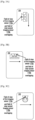
- FIGS. 3A, 3B, 3C , and 3D are examples illustrating a FOV of at least two imaging sensors of an electronic device, according to various embodiments of the disclosure.
- the electronic device 100 has two imaging sensors 110a and 110b.
- the electronic device 100 In order to capture the first image and the second image of the finger of the user, the electronic device 100 initially determines whether the finger of the user is placed such that the finger covers the first imaging sensor 110a and the second imaging sensor 110b completely. The electronic device 100 determines whether the finger of the user completely covers the two imaging sensors 110a and 110b by using variants of proximity sensors and advanced image processing techniques.
- the proposed method includes determining whether the first imaging sensor 110a and the second imaging sensor 110b have captured the same portion of the finger of the user by determining the overlapping portions in the first image and the second image (i.e., the overlapping portions of the finger vein structure in the first image and the second image).
- the same portion of the finger vein structure can be captured in consecutive frames by the first imaging sensor 110a and the second imaging sensor 110b or in subsequent frames by capturing a delayed video of the finger.
- the video frames comprising the same portion of the finger of the user may appear after certain time delay and may not appear in the consecutive video frames.
- the distance between the first imaging sensor 110a and the second imaging sensor 110b determines whether the same portion of the finger can be captured in consecutive video frames or the delayed video of the finger needs to be captured.
- the FOV of the first imaging sensor 110a and the second imaging sensor 110b are cone shaped and the fields of view originate at the center of the first imaging sensor 110a and the second imaging sensor 110b respectively. If the cones of the first imaging sensor 110a and the second imaging sensor 110b do not intersect each other within the finger, then the first imaging sensor 110a and the second imaging sensor 110b are not imaging the same portion of the finger simultaneously. Further, the intersection of the FOV depends on the distance between the first imaging sensor 110a and the second imaging sensor 110b. In general, the inter-imaging sensor distances are in the range of 0.8 cm to 2.5 cm.
- the first imaging sensor 110a and the second imaging sensor 110b with shorter inter-imaging sensor distances capture the same portion of the finger in the consecutive frames since the fields of view of the first imaging sensor 110a and the second imaging sensor 110b overlaps, as shown in FIGS. 3A-3C .
- the first imaging sensor 110a and the second imaging sensor 110b with longer inter-imaging sensor distances require the delayed video to capture the same portion of the finger, since the FOV of the first imaging sensor 110a and the FOV of the second imaging sensor 110b does not overlap at the given instant of time, as shown in FIG. 3D . Accordingly, the stereo video of the finger vein structure has to be captured to be able to generate the 3D biometric model of the finger vein structure.
- FIGS. 4A and 4B are illustrations in which an electronic device generates a 3D biometric model of a finger vein structure of a user, according to various embodiments of the disclosure.
- finger veins are sub-dermal (i.e., the finger veins are located below the skin) and have a three-dimensional structure.
- the finger vein structure is unique for every user and hence can be used as a biometric in various applications. Since the finger veins are located deep within the user's finger, the finger vein structure cannot be replicated and is thus spoof free. Also, since the finger vein structures are sub-dermal, related art techniques for capturing the structure require complex structures.
- the proposed method uses the electronic device including the at least two imaging sensors to capture the finger vein structures. The proposed method includes illuminating the finger with an infrared light beam. The infrared light beam travels through the finger and highlights the vein pattern within the finger of the user.
- the finger vein structure is then captured as an image using the at least two imaging sensors.
- the finger vein structure has lower false rejection rate (FRR) and lower false acceptance rate (FAR) as compared to traditional biometrics due to the sub-dermal feature. Further, the finger vein structure is not affected by weather or age related effects on the skin surface.
- the electronic device 100 determines that the user has placed the finger on the first imaging sensor 110a and the second imaging sensor 110b such that the finger covers the first imaging sensor 110a and the second imaging sensor 110b completely.
- the illuminating sensor 114b of the second imaging sensor 110b and the image capturing sensor 112a of the first imaging sensor 110a are activated simultaneously.
- the first imaging sensor 110a captures the first image which includes the first portion of the finger which is within the FOV of the first imaging sensor 110a and illuminated by the second imaging sensor 110b, as shown in FIG. 4A .
- the electronic device 100 then detects a sliding motion of the finger on the first imaging sensor 110a and the second imaging sensor 110b in the direction as indicated in FIG. 4A .
- the illuminating sensor 114a of the first imaging sensor 110a and the image capturing sensor 112b of the second imaging sensor 110b are activated simultaneously.
- the second imaging sensor 110b captures the second image which includes the second portion of the finger which is within the FOV of the second imaging sensor 110b and illuminated by the first imaging sensor 110a, as shown in FIG. 4B .
- the electronic device 100 determines whether at least one location of the first portion in the first image of the finger overlaps with the second portion in the second image of the finger of the user at the given instant of time. According to determining that the at least one location of the first portion in the first image of the finger overlaps the second portion in the second image of the finger, the electronic device 100 uses the first image and the second image to generate the 3D biometric model of the finger vein structure of the user.
- the electronic device 100 Upon determining that the at least one location of the first portion in the first image of the finger does not overlap with the second portion in the second image of the finger at the given instant of time, the electronic device 100 records a video of the finger of the user by sliding the finger along the first imaging sensor 110a and the second imaging sensor 110b, in the direction as indicated in FIGS. 4A and 4B .
- the images or frames capturing the same region of the finger may be captured at a later period of time in the video. For example, a portion of the finger may be captured in the first frame of the video by the first imaging sensor 110a. The user performs the sliding movement of the finger so that the same portion of the finger moves into the FOV of the second imaging sensor 110b.
- the same portion of the finger is again captured in the 20 th frame of the video which appears after a time delay.
- the video is then used to determine the first frame and the 20 th frame which have captured the same portion of the finger.
- the first frame and the 20 th frame of the video are also used to create the depth map of the finger vein structure, which is then used to generate the 3D biometric model of the user's finger vein structure.
- FIG. 5 is a flow chart illustrating a method for generating a 3D biometric model of a user's finger vein structure, according to an embodiment of the disclosure.
- the electronic device 100 detects the finger of the user.
- the at least two imaging sensors 110a and 110b can be configured to detect the user's finger.
- the electronic device 100 illuminates the first portion of the finger.
- the second imaging sensor 110b can be configured to illuminate the first portion of the finger.
- the electronic device 100 captures the first image of the first portion of the finger.
- the first imaging sensor 110a can be configured to capture the first image of the first portion of the finger.
- the electronic device 100 illuminates the second portion of the finger.
- the first imaging sensor 110a can be configured to illuminate the second portion of the finger.
- the electronic device 100 captures the second image of the second portion of the finger.
- the second imaging sensor 110b can be configured to capture the second image of the second portion of the finger.
- the electronic device 100 determines whether the first portion of finger and the second portion of finger overlap at the given instant of time.
- the 3D modeling engine 1120 can be configured to determine whether first portion of finger and second portion of finger overlap at the given instant of time.
- the electronic device 100 Upon determining that the first portion of the finger and the second portion of the finger overlap at the given instant of time, at operation 514, the electronic device 100 generates the 3D biometric model of the finger vein structure.
- the 3D modeling engine 1120 can be configured to dynamically generate the 3D biometric model of the finger vein structure.
- the electronic device 100 Upon determining that the first portion of the finger and the second portion of the finger do not overlap at the given instant of time, at operation 516, the electronic device 100 captures the stereo video of the finger.
- the at least two imaging sensors 110a and 110b can be configured to capture the stereo video of the finger.
- the stereo video includes a plurality of images (frames) of the finger which captures the finger vein structure. The first portion of the finger and the second portion of the finger will overlap at a later point of time in one of the subsequent images (frames) of the stereo video.
- the electronic device 100 determines the images (frames) from the stereo video having the first portion of the finger and the second portion of the finger overlapping.
- the 3D modeling engine 1120 can be configured to determine the images (frames) from the stereo video having the first portion of the finger and the second portion of the finger overlapping.
- the electronic device 100 loops to operation 514 and dynamically generates the 3D biometric model of the finger vein structure using the images from the stereo video which have the first portion of the finger and the second portion of the finger overlapping.
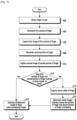
- FIG. 6 is a flow chart illustrating a method for generating a 3D biometric model of a finger using images, according to an embodiment of the disclosure.
- the electronic device 100 estimates a video-frame of a second portion of a finger, matching to a first portion of the finger. If no overlap, the electronic device 100 estimates based on a stereo camera baseline, a frame-rate, and a sliding finger speed estimated from a touchscreen speed or a camera Image speed of the finger, and so on.
- the electronic device 100 Given an input of matching left and right infrared (IR) finger vein images, the known stereo camera baseline, sets up a well-known epipolar geometrical computation framework. At operation 606, the electronic device 100 computes a stereo correspondence of vein segments between the left and right vein images.
- IR infrared
- the electronic device 100 computes a stereo disparity from the stereo correspondence, and estimates or refines a depth of each vein point using standard 3D construction methods.
- the electronic device 100 determines whether a current depth reconstruction is accurately converged. When a vein axis is parallel to the stereo camera baseline, it will be difficult to estimate its depth with just one stereo image pair. As doing more iterations, the two ends of the vein segment will be revealed, thus increasing accuracy.
- the electronic device 100 obtains a next video frame of the second portion. Then, the electronic device 100 returns to the operation 602.
- a procedure described at FIG. 6 is performed completely for an image of a first portion of the finger.
- the procedure described at FIG. 6 may be repeatedly performed on other first portiosn of the finger in the video by shifting the first portion. That is, all operations at FIG. 6 are repeated about a next image of another first portion of the finger, until an entire finger is completed. If the finger is completed, the 3D biometric model is generated.
- At least two imaging sensors are utilized.
- a single imaging sensor may be utilized to generate a 3D biometric model of the finger vein structure.
- the single imaging sensor includes an image capturing sensor and at least two illuminating sensors.
- the at least two illuminating sensors are arranged around the image capturing sensor.
- the at least two illuminating sensors are arranged at different locations, as shown in FIGS. 7A and 7B .
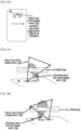
- FIGS. 7A and 7B are another example illustrations in which an electronic device generates a 3D biometric model of a user's finger vein structure, according to various embodiments of the disclosure.
- a first illuminating sensor 714a is arranged at left side of an image capturing sensor 712
- a second illuminating sensor 714b is arranged at right side of an image capturing sensor 712.
- the second illuminating sensor 714b is activated and the image capturing sensor 712 is controlled to capture a first image as shown in FIG. 7A .
- the first illuminating sensor 714a is activated and the image capturing sensor 712 is controlled to capture a second image as shown in FIG. 7B . Due to a difference between locations of the first illuminating sensor 714a and the second illuminating sensor 714b, the first image and the second image include different images of the same portion of the finger.
- a user interface for guiding a user in order to place the user's finger at proper location to capture images.
- An example of the UI is shown in FIG. 8 .
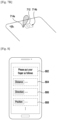
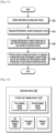
- FIG. 8 is an example illustration of a UI displayed in an electronic device according to an embodiment of the disclosure.
- the electronic device 100 displays the UI for guiding the user.
- the UI includes at least one of a title item 802, a first guide item 804 regarding to a distance between a finger and an image sensor, a second guide item 806 regarding to a slide direction (i.e., 'left to right', 'right to left' and so on), and a third guide item 808 regarding to a position of the finger to be captured.
- at least one of the items 802, 804, 806 and 808 may be text, images or moving images.
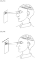
- FIGS. 9A and 9B are example scenarios illustrating an electronic device generating a 3D biometric model of a user's iris, according to various embodiments of the disclosure.
- the iris is a structure in the eyes that is an intricately woven web of blood vessels and cells.
- the iris is formed at the early stages of an individual's life and the texture remains stable during the lifetime of the individual. Further, even genetically identical individuals have distinct iris textures which make the use of iris for authentication purposes highly accurate and reliable.
- the iris has complex patterns that are unique for every user. Iris recognition uses video camera technology with subtle near infrared illumination to acquire images of the detail-rich, intricate structures of the iris which are visible externally according to the related art.
- the electronic device 100 has the first imaging sensor 110a and the second imaging sensor 110b.
- the electronic device 100 is placed in front of the eyes of the user such that the iris is within the FOV of the first imaging sensor 110a of the electronic device 100.
- the iris is illuminated by the second imaging sensor 110b of the electronic device 100 and the first imaging sensor 110a captures the first image of the iris of the eye.
- the iris is illuminated by the first imaging sensor 110a and the second imaging sensor 110b captures the second image of the iris of the eye.
- the first image and the second image of the iris are registered (i.e., image registration is performed).
- a difference between the first image and the second image of the iris is determined.
- the difference value between the first image and the second image of the iris provides an indication of the 3D structure of the iris.
- the electronic device 100 is moved across the user's face (as shown in FIG. 9B ) to bring the iris into the FOV of the second imaging sensor 110b of the electronic device 100 to obtain an alternating stereo video of the iris.
- the alternating stereo video is captured with high frame rate to avoid flicker issues.
- the alternating stereo video is captured using the cross-paired setup where the first imaging sensor 110a of the at least two imaging sensors 110a and 110b is used to illuminate the iris while the second imaging sensor 110b is used to capture the image of the iris.
- the second imaging sensor 110b of the at least two imaging sensors 110a and 110b are used to illuminate the iris while the first imaging sensor 110a is used to capture the image of the iris.
- the 3D biometric model of the iris is generated using the difference between multiple images (frames) obtained in the stereo video of the iris.
- the 3D biometric model of the iris can be used for spoof free biometric authentication of the user.
- the main advantage of using iris for authentication is the speed of matching and the resistance to false matches.
- FIG. 10 is a flow chart illustrating a method for generating a 3D biometric model of a user's iris, according to an embodiment of the disclosure.
- the electronic device 100 detects the user's iris within the FOV.
- the at least two imaging sensors 1210a and 1210b can be configured to detect that the iris of the user is within the FOV.
- the electronic device 100 illuminates the iris.
- the second imaging sensor 110b can be configured to illuminate the iris.
- the electronic device 100 captures the first image of the iris.
- the first imaging sensor 1210a can be configured to capture the first image of the iris.
- the electronic device 100 illuminates the iris.
- the first imaging sensor 110a can be configured to illuminate the iris.
- the electronic device 100 captures the second image of the iris.
- the second imaging sensor 1210b can be configured to capture the second image of the iris.
- the electronic device 100 registers the first image and the second image and obtains the difference between the first image and the second image.
- the 3D modeling engine 1220 can be configured to register the first image and the second image and obtain the difference between the first image and the second image.
- the electronic device 100 obtains an alternating stereo video of the iris.
- the at least two imaging sensors 1210a and 1210b can be configured to obtain the alternating stereo video of the iris.
- the electronic device 100 generates the 3D biometric model of the iris using the difference between multiple images of the stereo video of the iris.
- the 3D modeling engine 1220 can be configured to dynamically generate the 3D biometric model of the iris using the difference between multiple images of the stereo video of the iris.
- FIG. 11 is a flow chart illustrating a method for performing actions based on a 3D biometric model of a user's body part, according to an embodiment of the disclosure.
- the electronic device 100 obtains information on the user's body part.
- the at least two imaging sensors 1210a and 1210b can be configured to obtain the information on the body part of the user.
- the electronic device 100 generates the 3D biometric model of the user's body part.
- the 3D modeling engine 1220 can be configured to generate the 3D biometric model of the body part of the user.
- the electronic device 100 compares the 3D biometric model of the user's body part with the 3D biometric model of the user's body part that is already stored in the electronic device 100.
- the 3D modeling engine 1220 can be configured to compare the 3D biometric model of the body part of the user with the 3D biometric model of the body part of user which is already stored in the electronic device 100.
- the electronic device 100 performs actions in response to determining that the 3D biometric model of the user's body part matches the 3D biometric model of the user's body part stored in the electronic device 100.
- the 3D modeling engine 1220 can be configured to perform actions in response to determining that the 3D biometric model of the user's body part matches the 3D biometric model of the user's body part stored in the electronic device 100.
- FIG. 12 is a block diagram illustrating various hardware elements of an electronic device for generating a 3D biometric model of a user's body part, according to an embodiment of the disclosure.
- the electronic device 100 can be, for example, a mobile phone, a smart phone, personal digital assistants (PDAs), a tablet, a wearable device, display devices, Internet of things (IoT) devices, electronic circuit, chipset, and electrical circuit (i.e., system on chip (SoC)), etc.
- PDAs personal digital assistants
- SoC system on chip
- the electronic device 100 can include at least one imaging sensor 1210, a 3D modeling engine 1220, a processor 1230, and a memory 1240.
- the at least two imaging sensors 1210 includes a first imaging sensor 1210a and a second imaging sensor 1210b.
- Each of the imaging sensors is a pair of an image capturing sensor (e.g., camera) and an illuminating sensor (e.g., light emitting diode (LED)).
- the at least two imaging sensors 1210a and 1210b emits light that is capable of penetrating through skin and illuminate the user's body part of the user (e.g., near infrared light).
- a single imaging sensor may be included.
- the single imaging sensor includes an image capturing sensor and at least two illuminating sensors that are arranged around the image capturing sensor.
- the at least two imaging sensors 1210a and 1210b are configured to detect that the body part of the user is within the FOV of the at least two imaging sensors 1210.
- the at least two imaging sensors 1210a and 1210b detects the body part is within the FOV of the at least two imaging sensors 1210a and 1210b based on various proximity sensors, advanced image processing techniques, light sensors and the like.
- the at least two imaging sensors 1210a and 1210b are also configured to automatically capture the first image of the first portion of the body part and the second image of the second portion of the body part of the user.
- the first image of the first portion of the body part and the second image of the second portion of the body part are captured by alternating the crossed-pair of the at least two imaging sensors 1210.
- the alternating crossed-pairing of the first imaging sensor 1210a and the second imaging sensor 1210b can be done manually by the user.
- the first image of the first portion of the body part includes a subcutaneous pattern/ structure at a first location of the body part.
- the second image of the second portion of the body part includes a subcutaneous pattern/ structure at a second location of the body part.
- the at least two imaging sensors 1210a and 1210b is also configured to record the delayed stereo video of the body part by sliding the body part across the at least two imaging sensors 1210, when the 3D modeling engine 1220 determines that the first portion of the first image of the body part and the second portion of the second image of the body part do not overlap at the given instant of time.
- the delayed stereo video of the body part includes continuously capturing the subcutaneous pattern/ structure of the body part in the subsequent frames of the video.
- the at least two imaging sensors 1210a and 1210b are configured to capture the delayed stereo video of the body part by moving the electronic device 100 across the user's body part (e.g., the iris).
- the frame rate is maintained at a specific level to avoid flicker issues.
- the 3D modeling engine 1220 may be configured to compare the first image of the body part and the second image of the body part based on image similarity techniques to determine whether the first portion of the first image of the body part and the second portion of the second image of the body part overlaps.
- the 3D modeling engine 1220 may be configured to generate the 3D biometric model of the body part on determining that the first portion of the first image of the body part and the second portion of the second image of the body part overlaps at the given instant of time. The first portion of the first image of the body part and the second portion of the second image of the body part overlaps when the first image and the second image have captured the same portion of the body part of the user.
- the 3D modeling engine 1220 Upon determining that the first portion of the first image of the body part and the second portion of the second image of the body part do not overlap, the 3D modeling engine 1220 is configured to trigger the at least two imaging sensors 1210a and 1210b to record the delayed video of the body part of the user by sliding the body part across the at least two imaging sensors 120.
- the 3D modeling engine 1220 may be configured to determine the images (i.e., video frames) in the video which have the same portion of the body part of the user and use the images to generate the 3D biometric model of the body part of the user.
- the 3D modeling engine 1220 may be configured to register the first image and the second image of the body part of the user and obtain the difference between the first image and the second image.
- the 3D modeling engine 1220 may also be configured to obtain an alternating stereo video of the body part of the user.
- the 3D modeling engine 1220 may also be configured to determine the difference between the multiple images of the stereo video of the body part and dynamically generate the 3D biometric model of the body part using the difference between multiple images.
- the 3D modeling engine 1220 may also be configured to retrieve the 3D biometric model of the body part which is stored in the memory 1240 and compare the retrieved the 3D biometric model of the body part with a current 3D biometric model of the body part to perform actions on the electronic device.
- the actions can be associated with authentication and access control applications such as at least one of locking the electronic device, unlocking the electronic device, locking an application in the electronic device, unlocking an application in the electronic device, etc.
- the processor 1230 can be configured to interact with the hardware elements such as the at least one imaging sensor 1210, the 3D modeling engine 1220, and the memory 1240 for generating the 3D biometric model of the body part of the user.
- the processor 1230 may include one or more processors configured to control various components of the electronic device 100.
- the memory 1140 may be configured to store the 3D biometric model of the body part generated by the 3D modeling engine 1220.
- the 3D biometric model of the body part which is stored in the memory 1240 is retrieved and compared with a current 3D biometric model of the body part generated by the 3D modeling engine 1220 for various authentication and access control applications.
- the memory 1240 can include non-volatile storage elements. Examples of such non-volatile storage elements may include magnetic hard discs, optical discs, floppy discs, flash memories, or forms of electrically programmable memories (EPROM) or electrically erasable and programmable (EEPROM) memories.
- EPROM electrically programmable memories
- EEPROM electrically erasable and programmable
- the memory 140 may, in some examples, be considered a non-transitory storage medium.
- non-transitory may indicate that the storage medium is not embodied in a carrier wave or a propagated signal. However, the term “non-transitory” should not be interpreted that the memory 1240 is non-movable. In some examples, the memory 1240 can be configured to store larger amounts of information than the memory. In certain examples, a non-transitory storage medium may store data that can, over time, change (e.g., in random access memory (RAM) or cache).
- RAM random access memory
- the electronic device 100 can include a display (not shown).
- the display is used to display a user interface (e.g., the user interface as shown at FIG. 8 ).
- FIG. 12 shows the hardware elements of the electronic device 100, it is to be understood that other embodiments are not limited thereon.
- the electronic device 100 may include a larger or smaller number of elements.
- the labels or names of the elements are used only for illustrative purpose and does not limit the scope of the disclosure.
- One or more components can be combined together to perform same or substantially similar function for generating the 3D biometric model of the body part of the user using an electronic device 100.
- the embodiments disclosed herein can be implemented using at least one software program running on at least one hardware device and performing network management functions to control the elements.
Landscapes
- Engineering & Computer Science (AREA)
- Physics & Mathematics (AREA)
- Theoretical Computer Science (AREA)
- General Physics & Mathematics (AREA)
- Multimedia (AREA)
- Human Computer Interaction (AREA)
- Software Systems (AREA)
- Computer Security & Cryptography (AREA)
- Computer Hardware Design (AREA)
- General Engineering & Computer Science (AREA)
- Computer Graphics (AREA)
- Geometry (AREA)
- Signal Processing (AREA)
- Artificial Intelligence (AREA)
- Computer Vision & Pattern Recognition (AREA)
- Health & Medical Sciences (AREA)
- General Health & Medical Sciences (AREA)
- Ophthalmology & Optometry (AREA)
- Measurement Of The Respiration, Hearing Ability, Form, And Blood Characteristics Of Living Organisms (AREA)
- Image Input (AREA)
Claims (6)
- Procédé permettant la génération d'un modèle biométrique tridimensionnel (3D) d'une partie corporelle d'un utilisateur à l'aide d'un dispositif électronique (100), le procédé comprenant :la détection, à l'aide d'au moins un capteur d'imagerie (110) du dispositif électronique (100), de la partie corporelle ;la capture, à l'aide du au moins un capteur d'imagerie (110), d'une première image d'une première partie de la partie corporelle ;la détection d'un mouvement de coulissement de la partie corporelle ;la capture, à l'aide du au moins un capteur d'imagerie (110), d'une seconde image d'une seconde partie de la partie corporelle, en réponse à la détection du mouvement de coulissement de la partie corporelle ;la détermination pour savoir si la première partie dans la première image chevauche la seconde partie dans la seconde image ;la génération du modèle biométrique 3D de la partie corporelle à l'aide de la première image et de la seconde image de la partie corporelle, lors de la détermination que la première partie dans la première image chevauche la seconde partie dans la seconde image ; etle stockage du modèle biométrique 3D de la partie corporelle dans le dispositif électronique (100).
- Procédé de la revendication 1, comprenant en outre :l'obtention d'informations sur la partie corporelle ;la génération du modèle biométrique 3D de la partie corporelle ;la comparaison du modèle biométrique 3D de la partie corporelle avec le modèle biométrique 3D stocké de la partie corporelle ; etla réalisation d'actions sur le dispositif électronique (100), en réponse à la détermination que le modèle biométrique 3D de la partie corporelle correspond au modèle biométrique 3D de la partie corporelle stocké dans le dispositif électronique (100).
- Dispositif électronique (100) destiné à générer un modèle biométrique tridimensionnel (3D) d'une partie corporelle d'un utilisateur, le dispositif électronique comprenant :au moins un processeur (1230) couplé à une mémoire (1240) ;au moins un capteur d'imagerie (1210) couplé à l'au moins un processeur (1230), ledit au moins un capteur d'imagerie (1210) étant configuré pour :détecter la partie corporelle,capturer une première image d'une première partie de la partie corporelle,détecter un mouvement de coulissement de la partie corporelle,capturer une seconde image d'une seconde partie de la partie corporelle, en réponse à la détectiondu mouvement de coulissement de la partie corporelle, et déterminer si la première partie dans la première image chevauche la seconde partie dans la seconde image ;un moteur de modélisation 3D (1220) couplé à l'au moins un processeur (1230) et à la mémoire (1240),ledit au moins un processeur (1230) étant configuré pour commander le moteur de modélisation 3D (1220) afin de générer le modèle biométrique 3D de la partie corporelle à l'aide de la première image et de la seconde image de la partie corporelle, lors de la détermination que la première partie dans la première image chevauche la seconde partie dans la seconde image, etladite mémoire (1240) étant configurée pour stocker le modèle biométrique 3D de la partie corporelle.
- Dispositif électronique (100) de la revendication 3, ledit au moins un processeur (1230) étant en outre configuré pour :obtenir des informations sur la partie corporelle,générer le modèle biométrique 3D de la partie corporelle,comparer le modèle biométrique 3D de la partie corporelle de l'utilisateur avec le modèle biométrique 3D de la partie corporelle de l'utilisateur stocké dans le dispositif électronique (100), etréaliser des actions sur le dispositif électronique (100), en réponse à la détermination que le modèle biométrique 3D de la partie corporelle de l'utilisateur correspond au modèle biométrique 3D de la partie corporelle stocké dans le dispositif électronique (100).
- Dispositif électronique (100) de la revendication 4, lesdites actions comprenant au moins l'une du verrouillage du dispositif électronique (100), du déverrouillage du dispositif électronique (100), du verrouillage d'une application dans le dispositif électronique (100), ou du déverrouillage d'une application dans le dispositif électronique (100).
- Dispositif électronique (100) de la revendication 3, ladite partie corporelle comprenant l'un d'une veine de doigt ou d'un iris de l'utilisateur.
Applications Claiming Priority (2)
| Application Number | Priority Date | Filing Date | Title |
|---|---|---|---|
| IN201741025468 | 2017-07-18 | ||
| PCT/KR2018/008112 WO2019017686A1 (fr) | 2017-07-18 | 2018-07-18 | Procédé de génération d'un modèle biométrique 3d d'une partie corporelle d'un utilisateur et dispositif électronique associé |
Publications (3)
| Publication Number | Publication Date |
|---|---|
| EP3625728A1 EP3625728A1 (fr) | 2020-03-25 |
| EP3625728A4 EP3625728A4 (fr) | 2020-08-12 |
| EP3625728B1 true EP3625728B1 (fr) | 2025-03-26 |
Family
ID=65019047
Family Applications (1)
| Application Number | Title | Priority Date | Filing Date |
|---|---|---|---|
| EP18834583.9A Active EP3625728B1 (fr) | 2017-07-18 | 2018-07-18 | Procédé de génération d'un modèle biométrique 3d d'une partie corporelle d'un utilisateur et dispositif électronique associé |
Country Status (3)
| Country | Link |
|---|---|
| US (1) | US10776469B2 (fr) |
| EP (1) | EP3625728B1 (fr) |
| WO (1) | WO2019017686A1 (fr) |
Families Citing this family (5)
| Publication number | Priority date | Publication date | Assignee | Title |
|---|---|---|---|---|
| US11657570B2 (en) | 2020-06-02 | 2023-05-23 | Koninklijke Philips N.V. | Creating a 3D model using two or more cameras with variable focal lengths |
| CN113076921B (zh) * | 2021-04-21 | 2022-11-18 | 华南理工大学 | 一种三维指部生物特征模型的多光谱纹理同步映射方法 |
| WO2022249011A1 (fr) | 2021-05-25 | 2022-12-01 | Applications Mobiles Overview Inc. | Système et procédé pour fournir des transactions personnalisées basées sur des représentations 3d de caractéristiques physiques d'utilisateur |
| US20250028801A1 (en) * | 2023-07-19 | 2025-01-23 | Plume Design, Inc. | Computerized systems and methods for biometric authentication via a smart wearable device |
| FR3161970A1 (fr) * | 2024-06-10 | 2025-11-07 | Idemia Identity & Security France | Dispositif et procede d’acquisition sans contact d’image de dermatoglyphe |
Family Cites Families (11)
| Publication number | Priority date | Publication date | Assignee | Title |
|---|---|---|---|---|
| KR20040006703A (ko) | 2002-07-13 | 2004-01-24 | 엘지전자 주식회사 | 홍채 인식 시스템 |
| JP2006103453A (ja) | 2004-10-04 | 2006-04-20 | Takata Corp | シートベルトリトラクタおよびこれを用いたシートベルト装置 |
| WO2007024259A2 (fr) * | 2005-02-17 | 2007-03-01 | Authentec, Inc. | Appareil a capteur de doigt utilisant le reechantillonnage des images et procedes correspondants |
| US9202105B1 (en) | 2012-01-13 | 2015-12-01 | Amazon Technologies, Inc. | Image analysis for user authentication |
| US9396382B2 (en) * | 2012-08-17 | 2016-07-19 | Flashscan3D, Llc | System and method for a biometric image sensor with spoofing detection |
| JP2014199492A (ja) | 2013-03-29 | 2014-10-23 | 株式会社ジャパンディスプレイ | 電子機器および電子機器の制御方法 |
| US9898642B2 (en) * | 2013-09-09 | 2018-02-20 | Apple Inc. | Device, method, and graphical user interface for manipulating user interfaces based on fingerprint sensor inputs |
| EP3061023B1 (fr) * | 2013-10-25 | 2020-01-01 | OneVisage SA | Procédé et système de mise en oeuvre de vérification d'identité reposant sur un modèle 3d d'individus à l'aide de dispositifs mobiles |
| WO2017076292A1 (fr) * | 2015-11-02 | 2017-05-11 | Shenzhen Huiding Technology Co., Ltd. | Capteur d'empreintes digitales multifonction doté d'une détection optique contre les contrefaçons d'empreintes digitales |
| KR101728970B1 (ko) * | 2015-12-11 | 2017-04-20 | 연세대학교 산학협력단 | 광을 이용한 3차원 생체 정보 감지 장치 및 생체 정보 감지 방법 |
| US10372974B2 (en) * | 2017-01-11 | 2019-08-06 | Microsoft Technology Licensing, Llc | 3D imaging recognition by stereo matching of RGB and infrared images |
-
2018
- 2018-07-18 EP EP18834583.9A patent/EP3625728B1/fr active Active
- 2018-07-18 US US16/038,749 patent/US10776469B2/en not_active Expired - Fee Related
- 2018-07-18 WO PCT/KR2018/008112 patent/WO2019017686A1/fr not_active Ceased
Also Published As
| Publication number | Publication date |
|---|---|
| EP3625728A4 (fr) | 2020-08-12 |
| EP3625728A1 (fr) | 2020-03-25 |
| US20190026451A1 (en) | 2019-01-24 |
| US10776469B2 (en) | 2020-09-15 |
| WO2019017686A1 (fr) | 2019-01-24 |
Similar Documents
| Publication | Publication Date | Title |
|---|---|---|
| EP3625728B1 (fr) | Procédé de génération d'un modèle biométrique 3d d'une partie corporelle d'un utilisateur et dispositif électronique associé | |
| CN106991377B (zh) | 结合深度信息的人脸识别方法、人脸识别装置和电子装置 | |
| US10339402B2 (en) | Method and apparatus for liveness detection | |
| CN107506684B (zh) | 步态识别方法及装置 | |
| EP3241151B1 (fr) | Procédé et appareil de traitement de visage dans une image | |
| WO2019080580A1 (fr) | Procédé et appareil d'authentification d'identité de visage 3d | |
| WO2019080578A1 (fr) | Procédé et appareil d'authentification d'identité de visage 3d | |
| US20100098299A1 (en) | Information Extraction Method, Information Extraction Device, Program, Registration Device, and Verification Device | |
| WO2019080579A1 (fr) | Procédé et appareil d'authentification d'identité de visage en 3d | |
| CN105993022B (zh) | 利用脸部表情识别和认证的方法和系统 | |
| CN111382592B (zh) | 活体检测方法和设备 | |
| CN106133752A (zh) | 眼睛注视跟踪 | |
| JP2013522754A (ja) | 複数の虹彩テンプレートを用いた虹彩認識装置及び方法 | |
| CN113330433B (zh) | 用于认证用户的方法及其电子设备 | |
| US20210350126A1 (en) | Iris authentication device, iris authentication method, and recording medium | |
| JPWO2020065954A1 (ja) | 認証装置、認証方法、認証プログラムおよび記録媒体 | |
| US10748025B2 (en) | Method, apparatus, and non-transitory computer-readable storage medium for verification process | |
| CN110555348A (zh) | 一种指纹识别方法、设备及计算机可读存储介质 | |
| CN112989902B (zh) | 活体测试方法和活体测试装置 | |
| JP5789691B2 (ja) | 個人認証装置、及び血管画像撮影装置 | |
| JP7524953B2 (ja) | 凝視に基づくライブネス検出のための情報処理装置、情報処理方法、およびプログラム | |
| CN112766175B (zh) | 活体检测方法、装置及非易失性存储介质 | |
| US11200401B2 (en) | Method and device for biometric vascular recognition and/or identification | |
| JP5134655B2 (ja) | 個人認証システム、個人認証装置、及び血管画像撮影装置 | |
| Chopra et al. | Finger print and finger vein recognition using repeated line tracking and minutiae |
Legal Events
| Date | Code | Title | Description |
|---|---|---|---|
| STAA | Information on the status of an ep patent application or granted ep patent |
Free format text: STATUS: THE INTERNATIONAL PUBLICATION HAS BEEN MADE |
|
| PUAI | Public reference made under article 153(3) epc to a published international application that has entered the european phase |
Free format text: ORIGINAL CODE: 0009012 |
|
| STAA | Information on the status of an ep patent application or granted ep patent |
Free format text: STATUS: REQUEST FOR EXAMINATION WAS MADE |
|
| 17P | Request for examination filed |
Effective date: 20191217 |
|
| AK | Designated contracting states |
Kind code of ref document: A1 Designated state(s): AL AT BE BG CH CY CZ DE DK EE ES FI FR GB GR HR HU IE IS IT LI LT LU LV MC MK MT NL NO PL PT RO RS SE SI SK SM TR |
|
| AX | Request for extension of the european patent |
Extension state: BA ME |
|
| RIC1 | Information provided on ipc code assigned before grant |
Ipc: H04N 13/00 20180101ALI20200403BHEP Ipc: G06T 17/00 20060101ALI20200403BHEP Ipc: G06K 9/00 20060101ALI20200403BHEP Ipc: G03B 35/00 20060101ALI20200403BHEP Ipc: G06F 21/32 20130101AFI20200403BHEP Ipc: G06K 9/20 20060101ALI20200403BHEP |
|
| A4 | Supplementary search report drawn up and despatched |
Effective date: 20200710 |
|
| RIC1 | Information provided on ipc code assigned before grant |
Ipc: G03B 35/00 20060101ALI20200706BHEP Ipc: H04N 13/00 20180101ALI20200706BHEP Ipc: G06K 9/20 20060101ALI20200706BHEP Ipc: G06K 9/00 20060101ALI20200706BHEP Ipc: G06F 21/32 20130101AFI20200706BHEP Ipc: G06T 17/00 20060101ALI20200706BHEP |
|
| DAV | Request for validation of the european patent (deleted) | ||
| DAX | Request for extension of the european patent (deleted) | ||
| STAA | Information on the status of an ep patent application or granted ep patent |
Free format text: STATUS: EXAMINATION IS IN PROGRESS |
|
| 17Q | First examination report despatched |
Effective date: 20221219 |
|
| REG | Reference to a national code |
Ref country code: DE Ref legal event code: R079 Free format text: PREVIOUS MAIN CLASS: G06K0009000000 Ipc: G06F0021320000 Ref country code: DE Ref legal event code: R079 Ref document number: 602018080536 Country of ref document: DE Free format text: PREVIOUS MAIN CLASS: G06K0009000000 Ipc: G06F0021320000 |
|
| GRAP | Despatch of communication of intention to grant a patent |
Free format text: ORIGINAL CODE: EPIDOSNIGR1 |
|
| STAA | Information on the status of an ep patent application or granted ep patent |
Free format text: STATUS: GRANT OF PATENT IS INTENDED |
|
| INTG | Intention to grant announced |
Effective date: 20241223 |
|
| RIC1 | Information provided on ipc code assigned before grant |
Ipc: G06V 40/14 20220101ALN20241213BHEP Ipc: G03B 35/08 20060101ALN20241213BHEP Ipc: H04N 23/60 20230101ALI20241213BHEP Ipc: H04N 23/56 20230101ALI20241213BHEP Ipc: G06V 40/19 20220101ALI20241213BHEP Ipc: G06V 40/13 20220101ALI20241213BHEP Ipc: G06V 40/10 20220101ALI20241213BHEP Ipc: G06V 20/64 20220101ALI20241213BHEP Ipc: G06V 10/145 20220101ALI20241213BHEP Ipc: G03B 35/00 20060101ALI20241213BHEP Ipc: H04N 13/00 20180101ALI20241213BHEP Ipc: G06T 17/00 20060101ALI20241213BHEP Ipc: G06F 21/32 20130101AFI20241213BHEP |
|
| GRAS | Grant fee paid |
Free format text: ORIGINAL CODE: EPIDOSNIGR3 |
|
| GRAA | (expected) grant |
Free format text: ORIGINAL CODE: 0009210 |
|
| STAA | Information on the status of an ep patent application or granted ep patent |
Free format text: STATUS: THE PATENT HAS BEEN GRANTED |
|
| AK | Designated contracting states |
Kind code of ref document: B1 Designated state(s): AL AT BE BG CH CY CZ DE DK EE ES FI FR GB GR HR HU IE IS IT LI LT LU LV MC MK MT NL NO PL PT RO RS SE SI SK SM TR |
|
| REG | Reference to a national code |
Ref country code: GB Ref legal event code: FG4D |
|
| REG | Reference to a national code |
Ref country code: CH Ref legal event code: EP |
|
| REG | Reference to a national code |
Ref country code: DE Ref legal event code: R096 Ref document number: 602018080536 Country of ref document: DE |
|
| REG | Reference to a national code |
Ref country code: IE Ref legal event code: FG4D |
|
| PG25 | Lapsed in a contracting state [announced via postgrant information from national office to epo] |
Ref country code: RS Free format text: LAPSE BECAUSE OF FAILURE TO SUBMIT A TRANSLATION OF THE DESCRIPTION OR TO PAY THE FEE WITHIN THE PRESCRIBED TIME-LIMIT Effective date: 20250626 |
|
| PG25 | Lapsed in a contracting state [announced via postgrant information from national office to epo] |
Ref country code: FI Free format text: LAPSE BECAUSE OF FAILURE TO SUBMIT A TRANSLATION OF THE DESCRIPTION OR TO PAY THE FEE WITHIN THE PRESCRIBED TIME-LIMIT Effective date: 20250326 |
|
| REG | Reference to a national code |
Ref country code: LT Ref legal event code: MG9D |
|
| PG25 | Lapsed in a contracting state [announced via postgrant information from national office to epo] |
Ref country code: NO Free format text: LAPSE BECAUSE OF FAILURE TO SUBMIT A TRANSLATION OF THE DESCRIPTION OR TO PAY THE FEE WITHIN THE PRESCRIBED TIME-LIMIT Effective date: 20250626 |
|
| PG25 | Lapsed in a contracting state [announced via postgrant information from national office to epo] |
Ref country code: HR Free format text: LAPSE BECAUSE OF FAILURE TO SUBMIT A TRANSLATION OF THE DESCRIPTION OR TO PAY THE FEE WITHIN THE PRESCRIBED TIME-LIMIT Effective date: 20250326 |
|
| PG25 | Lapsed in a contracting state [announced via postgrant information from national office to epo] |
Ref country code: LV Free format text: LAPSE BECAUSE OF FAILURE TO SUBMIT A TRANSLATION OF THE DESCRIPTION OR TO PAY THE FEE WITHIN THE PRESCRIBED TIME-LIMIT Effective date: 20250326 |
|
| PG25 | Lapsed in a contracting state [announced via postgrant information from national office to epo] |
Ref country code: GR Free format text: LAPSE BECAUSE OF FAILURE TO SUBMIT A TRANSLATION OF THE DESCRIPTION OR TO PAY THE FEE WITHIN THE PRESCRIBED TIME-LIMIT Effective date: 20250627 Ref country code: BG Free format text: LAPSE BECAUSE OF FAILURE TO SUBMIT A TRANSLATION OF THE DESCRIPTION OR TO PAY THE FEE WITHIN THE PRESCRIBED TIME-LIMIT Effective date: 20250326 |
|
| REG | Reference to a national code |
Ref country code: NL Ref legal event code: MP Effective date: 20250326 |
|
| PG25 | Lapsed in a contracting state [announced via postgrant information from national office to epo] |
Ref country code: NL Free format text: LAPSE BECAUSE OF FAILURE TO SUBMIT A TRANSLATION OF THE DESCRIPTION OR TO PAY THE FEE WITHIN THE PRESCRIBED TIME-LIMIT Effective date: 20250326 |
|
| PG25 | Lapsed in a contracting state [announced via postgrant information from national office to epo] |
Ref country code: SE Free format text: LAPSE BECAUSE OF FAILURE TO SUBMIT A TRANSLATION OF THE DESCRIPTION OR TO PAY THE FEE WITHIN THE PRESCRIBED TIME-LIMIT Effective date: 20250326 |
|
| REG | Reference to a national code |
Ref country code: AT Ref legal event code: MK05 Ref document number: 1779642 Country of ref document: AT Kind code of ref document: T Effective date: 20250326 |
|
| PG25 | Lapsed in a contracting state [announced via postgrant information from national office to epo] |
Ref country code: SM Free format text: LAPSE BECAUSE OF FAILURE TO SUBMIT A TRANSLATION OF THE DESCRIPTION OR TO PAY THE FEE WITHIN THE PRESCRIBED TIME-LIMIT Effective date: 20250326 |
|
| PG25 | Lapsed in a contracting state [announced via postgrant information from national office to epo] |
Ref country code: PT Free format text: LAPSE BECAUSE OF FAILURE TO SUBMIT A TRANSLATION OF THE DESCRIPTION OR TO PAY THE FEE WITHIN THE PRESCRIBED TIME-LIMIT Effective date: 20250728 Ref country code: ES Free format text: LAPSE BECAUSE OF FAILURE TO SUBMIT A TRANSLATION OF THE DESCRIPTION OR TO PAY THE FEE WITHIN THE PRESCRIBED TIME-LIMIT Effective date: 20250326 |
|
| PGFP | Annual fee paid to national office [announced via postgrant information from national office to epo] |
Ref country code: DE Payment date: 20250624 Year of fee payment: 8 |
|
| PG25 | Lapsed in a contracting state [announced via postgrant information from national office to epo] |
Ref country code: PL Free format text: LAPSE BECAUSE OF FAILURE TO SUBMIT A TRANSLATION OF THE DESCRIPTION OR TO PAY THE FEE WITHIN THE PRESCRIBED TIME-LIMIT Effective date: 20250326 Ref country code: IT Free format text: LAPSE BECAUSE OF FAILURE TO SUBMIT A TRANSLATION OF THE DESCRIPTION OR TO PAY THE FEE WITHIN THE PRESCRIBED TIME-LIMIT Effective date: 20250326 |
|
| PG25 | Lapsed in a contracting state [announced via postgrant information from national office to epo] |
Ref country code: AT Free format text: LAPSE BECAUSE OF FAILURE TO SUBMIT A TRANSLATION OF THE DESCRIPTION OR TO PAY THE FEE WITHIN THE PRESCRIBED TIME-LIMIT Effective date: 20250326 |
|
| PG25 | Lapsed in a contracting state [announced via postgrant information from national office to epo] |
Ref country code: EE Free format text: LAPSE BECAUSE OF FAILURE TO SUBMIT A TRANSLATION OF THE DESCRIPTION OR TO PAY THE FEE WITHIN THE PRESCRIBED TIME-LIMIT Effective date: 20250326 |
|
| PG25 | Lapsed in a contracting state [announced via postgrant information from national office to epo] |
Ref country code: RO Free format text: LAPSE BECAUSE OF FAILURE TO SUBMIT A TRANSLATION OF THE DESCRIPTION OR TO PAY THE FEE WITHIN THE PRESCRIBED TIME-LIMIT Effective date: 20250326 |
|
| PG25 | Lapsed in a contracting state [announced via postgrant information from national office to epo] |
Ref country code: SK Free format text: LAPSE BECAUSE OF FAILURE TO SUBMIT A TRANSLATION OF THE DESCRIPTION OR TO PAY THE FEE WITHIN THE PRESCRIBED TIME-LIMIT Effective date: 20250326 |
|
| PG25 | Lapsed in a contracting state [announced via postgrant information from national office to epo] |
Ref country code: IS Free format text: LAPSE BECAUSE OF FAILURE TO SUBMIT A TRANSLATION OF THE DESCRIPTION OR TO PAY THE FEE WITHIN THE PRESCRIBED TIME-LIMIT Effective date: 20250726 |
|
| REG | Reference to a national code |
Ref country code: DE Ref legal event code: R097 Ref document number: 602018080536 Country of ref document: DE |
|
| PG25 | Lapsed in a contracting state [announced via postgrant information from national office to epo] |
Ref country code: DK Free format text: LAPSE BECAUSE OF FAILURE TO SUBMIT A TRANSLATION OF THE DESCRIPTION OR TO PAY THE FEE WITHIN THE PRESCRIBED TIME-LIMIT Effective date: 20250326 |
|
| PG25 | Lapsed in a contracting state [announced via postgrant information from national office to epo] |
Ref country code: CZ Free format text: LAPSE BECAUSE OF FAILURE TO SUBMIT A TRANSLATION OF THE DESCRIPTION OR TO PAY THE FEE WITHIN THE PRESCRIBED TIME-LIMIT Effective date: 20250326 |
|
| PLBE | No opposition filed within time limit |
Free format text: ORIGINAL CODE: 0009261 |
|
| STAA | Information on the status of an ep patent application or granted ep patent |
Free format text: STATUS: NO OPPOSITION FILED WITHIN TIME LIMIT |
|
| REG | Reference to a national code |
Ref country code: CH Ref legal event code: L10 Free format text: ST27 STATUS EVENT CODE: U-0-0-L10-L00 (AS PROVIDED BY THE NATIONAL OFFICE) Effective date: 20260211 |
|
| REG | Reference to a national code |
Ref country code: CH Ref legal event code: H13 Free format text: ST27 STATUS EVENT CODE: U-0-0-H10-H13 (AS PROVIDED BY THE NATIONAL OFFICE) Effective date: 20260224 |
|
| 26N | No opposition filed |
Effective date: 20260105 |
|
| PG25 | Lapsed in a contracting state [announced via postgrant information from national office to epo] |
Ref country code: LU Free format text: LAPSE BECAUSE OF NON-PAYMENT OF DUE FEES Effective date: 20250718 |
|
| GBPC | Gb: european patent ceased through non-payment of renewal fee |
Effective date: 20250718 |
|
| REG | Reference to a national code |
Ref country code: BE Ref legal event code: MM Effective date: 20250731 |
|
| PG25 | Lapsed in a contracting state [announced via postgrant information from national office to epo] |
Ref country code: GB Free format text: LAPSE BECAUSE OF NON-PAYMENT OF DUE FEES Effective date: 20250718 |
|
| PG25 | Lapsed in a contracting state [announced via postgrant information from national office to epo] |
Ref country code: BE Free format text: LAPSE BECAUSE OF NON-PAYMENT OF DUE FEES Effective date: 20250731 |
|
| PG25 | Lapsed in a contracting state [announced via postgrant information from national office to epo] |
Ref country code: FR Free format text: LAPSE BECAUSE OF NON-PAYMENT OF DUE FEES Effective date: 20250731 |
|
| PG25 | Lapsed in a contracting state [announced via postgrant information from national office to epo] |
Ref country code: CH Free format text: LAPSE BECAUSE OF NON-PAYMENT OF DUE FEES Effective date: 20250731 |