EP3625976B1 - Verfahren zur bestimmung der entfernung zwischen ohren eines trägers eines schallerzeugungsobjekts und einem im ohr getragenen schallerzeugungsobjekt - Google Patents
Verfahren zur bestimmung der entfernung zwischen ohren eines trägers eines schallerzeugungsobjekts und einem im ohr getragenen schallerzeugungsobjekt Download PDFInfo
- Publication number
- EP3625976B1 EP3625976B1 EP18723040.4A EP18723040A EP3625976B1 EP 3625976 B1 EP3625976 B1 EP 3625976B1 EP 18723040 A EP18723040 A EP 18723040A EP 3625976 B1 EP3625976 B1 EP 3625976B1
- Authority
- EP
- European Patent Office
- Prior art keywords
- wearer
- sound generating
- head
- generating object
- accelerometer
- Prior art date
- Legal status (The legal status is an assumption and is not a legal conclusion. Google has not performed a legal analysis and makes no representation as to the accuracy of the status listed.)
- Active
Links
Images
Classifications
-
- H—ELECTRICITY
- H04—ELECTRIC COMMUNICATION TECHNIQUE
- H04S—STEREOPHONIC SYSTEMS
- H04S7/00—Indicating arrangements; Control arrangements, e.g. balance control
- H04S7/30—Control circuits for electronic adaptation of the sound field
- H04S7/302—Electronic adaptation of stereophonic sound system to listener position or orientation
- H04S7/303—Tracking of listener position or orientation
- H04S7/304—For headphones
-
- H—ELECTRICITY
- H04—ELECTRIC COMMUNICATION TECHNIQUE
- H04S—STEREOPHONIC SYSTEMS
- H04S7/00—Indicating arrangements; Control arrangements, e.g. balance control
- H04S7/30—Control circuits for electronic adaptation of the sound field
-
- H—ELECTRICITY
- H04—ELECTRIC COMMUNICATION TECHNIQUE
- H04R—LOUDSPEAKERS, MICROPHONES, GRAMOPHONE PICK-UPS OR LIKE ACOUSTIC ELECTROMECHANICAL TRANSDUCERS; ELECTRIC HEARING AIDS; PUBLIC ADDRESS SYSTEMS
- H04R25/00—Electric hearing aids
- H04R25/43—Electronic input selection or mixing based on input signal analysis, e.g. mixing or selection between microphone and telecoil or between microphones with different directivity characteristics
-
- H—ELECTRICITY
- H04—ELECTRIC COMMUNICATION TECHNIQUE
- H04S—STEREOPHONIC SYSTEMS
- H04S2420/00—Techniques used stereophonic systems covered by H04S but not provided for in its groups
- H04S2420/01—Enhancing the perception of the sound image or of the spatial distribution using head related transfer functions [HRTF's] or equivalents thereof, e.g. interaural time difference [ITD] or interaural level difference [ILD]
Definitions
- the disclosure primarily relates to a method for determining distance between ears of a wearer of a sound generating object.
- EP 2 890 161 presents a method of determining acoustic head size of a user wearing a pair of hearing aids.
- Minimum requirement in terms of equipment to arrive at the solution is to employ two hearing instruments and an intermediate signal provider, typically a mobile telephone. These devices communicate with each other using audio signals in order to determine acoustic time delay between the two ears so as to estimate the acoustic head size.
- acoustic head size may be defined as an acoustic distance between a pair of customarily arranged hearing aids. This acoustic distance is derived from the value of the time delay associated with the acoustic signals captured by the microphones of the respective hearing aid.
- US 2013/0177166 relates to head-related transfer function (hrtf) selection or adaptation based on head size and includes determining a user's head size and forwarding information associated with the user's head size to a processing device.
- hrtf head-related transfer function
- One objective of the invention at hand is therefore to at least alleviate drawbacks associated with the current art.
- a first aspect of the present disclosure provides a method for determining a distance (D) between ears of a wearer of a sound generating object, the method comprising: selecting a model for representing shape of the head of the wearer of the sound generating object so as to obtain a center axis of the wearer's head, wherein the center axis is an axis substantially perpendicular to a horizontal, ground plane and intersecting a head pivot point of the wearer's head; associating the first sound generating object with an ear of the wearer, wherein the first sound generating object comprises a first accelerometer and a second accelerometer, the respective accelerometers, i.e.
- the first accelerometer and the second accelerometer being arranged to measure at least an acceleration component (a1, a2) intersecting at a substantially right angle a center axis of the wearer's head, wherein the first and second accelerometers are so arranged that a straight line that intersects the center axis of the wearer's head at a substantially right angle crosses the first and second accelerometers such that the acceleration components (a1, a2) have the same direction, the first and second accelerometers being spaced by a known distance ( ⁇ r); when the head of the wearer is in motion, determining, by means of the first accelerometer, a value of the first acceleration component (a1) and, by means of the second accelerometer, a value of the second acceleration component (a2), determining the distance (D) between the ears of the wearer on the basis of the obtained values of the acceleration components (a1, a2).
- determining the distance (D) between the ears of the wearer is based on the model. In one or more exemplary methods, determining the distance (D) between the ears of the wearer is based on the known distance between the first accelerometer and the second accelerometer.
- center axis of the wearer's head is an axis substantially perpendicular to a horizontal, ground plane, said axis further intersecting a head pivot point, i.e. a point around which the head rotates side to side.
- associating the first sound generating object with an ear of the wearer entails arranging said object at or in proximity of the ear.
- an automatic adjustment of the distance between the ears of the wearer may be achieved.
- no involvement of the user is required in order to handily and accurately determine the ear-to-ear distance.
- said method is due to its inherent simplicity easily integrated in the existing software.
- the effect conferred by the inventive method is the improved fidelity with respect to presentation of the virtual (3D) audio signals generated by the sound generating object.
- more advanced beamforming models may be employed in the sound generating object, in particular in the hearing aid.
- estimation of the direction of arrival (DOA) of the speech signal could be significantly improved when the head size is accurately determined.
- a first sound generating object configured to be worn at an ear of a wearer
- the first sound generating object comprises means for allowing the wearer of the sound generating object to select a model for representing shape of the head so as to obtain a center axis of the wearer's head, wherein the center axis is an axis substantially perpendicular to a horizontal, ground plane and intersecting a head pivot point of the wearer's head, a first accelerometer and a second accelerometer, the respective accelerometers, i.e.
- the first accelerometer and the second accelerometer being arranged to measure at least an acceleration component (a1, a2) intersecting at a substantially right angle the center axis of the wearer's head, wherein the first and second accelerometers are so arranged that a straight line that intersects the center axis of the wearer's head at a substantially right angle crosses the first and second accelerometers such that the acceleration components (a1, a2) have the same direction, the first and second accelerometers being spaced by a known distance ( ⁇ r), wherein the first accelerometer is provided with means for determining a value of a first acceleration component (a1) and the second accelerometer is provided with means for determining a value of a second acceleration component (a2), and wherein the first, ear-worn, sound generating object (4) is provided with means for determining, on the basis of the obtained values of the acceleration components (a1, a2), a distance (D) between the ears of the wearer.
- ⁇ r known distance
- the means for determining the distance (D) between the ears of the wearer comprises means for determining the distance (D) between the ears of the wearer based on the model. In one or more exemplary first, ear-worn, sound generating objects, the means for determining the distance (D) between the ears of the wearer comprises means for determining the distance (D) between the ears of the wearer based on the known distance between the first accelerometer and the second accelerometer.
- a method for determining a distance (D) between ears of a wearer of a sound generating object comprises selecting a model for representing shape of the head of the wearer of the sound generating object so as to obtain a center axis of the wearer's head.
- the method comprises associating, such as arranging or positioning, the first sound generating object with an ear of the wearer, wherein the first sound generating object comprises a first accelerometer and a second accelerometer, the respective accelerometers being arranged to measure at least an acceleration component (a1, a2) intersecting at a substantially right angle the center axis of the wearer's head, wherein the first and second accelerometers are so arranged that a straight line that intersects the center axis of the wearer's head at a substantially right angle crosses the first and second accelerometers such that the acceleration components (a1, a2) have the same direction, the first and second accelerometers being spaced by a known distance.
- the first sound generating object is positioned or arranged at or near the wearer's ear, such as behind-the-ear, in-the-ear or partly within the ear.
- the method comprises determining, by means of the first accelerometer when the head of the wearer is in motion, a value of a first acceleration component (a1) and, by means of the second accelerometer, a value of a second acceleration component (a2), and determining the distance (D) between the ears of the wearer on the basis of the model, the obtained values of the first and second acceleration components (a1, a2), and the known distance between the first accelerometer and the second accelerometer.
- the first acceleration component may intersect at a substantially right angle the center axis of the wearer's head and/or the straight line crossing the first accelerometer and the second accelerometer.
- the first acceleration component may form a substantially right angle with the center axis of the wearer's head and/or the straight line crossing the first accelerometer and the second accelerometer.
- the second acceleration component may intersect at a substantially right angle the center axis of the wearer's head and/or the straight line crossing the first accelerometer and the second accelerometer.
- the second acceleration component may form a substantially right angle with the center axis of the wearer's head and/or the straight line crossing the first accelerometer and the second accelerometer.
- the distance (D) may be determined as a function of time and averaged over a time interval.
- the length of the time interval may be at least 60 seconds.
- a (first) ear-worn, sound generating object comprising means for allowing the wearer of the sound generating object to select a model for representing shape of the head so as to obtain a center axis of the wearer's head; a first accelerometer and a second accelerometer, the respective accelerometers being arranged to measure at least an acceleration component (a1, a2) intersecting at a substantially right angle the center axis of the wearer's head, wherein the first and second accelerometers are so arranged that a straight line that intersects the center axis of the wearer's head at a substantially right angle crosses the first and second accelerometers such that the acceleration components (a1, a2) have the same direction, the first and second accelerometers being spaced by a known distance; wherein the first accelerometer is provided with means for determining a value of a first acceleration component (a1) and the second accelerometer (12) is provided with means for determining a value of a second acceleration component (a2); and wherein the ear-worn,
- the sound generating object is configured to, when worn at the ear of the user, determine the distance (D) between the ears of the wearer based on first acceleration component and the second acceleration component.
- the acceleration components are determined in a plane substantially perpendicular to the center axis.
- the first, ear-worn, sound generating object may be a hearing instrument.
- the sound generating object may be enclosed by an earpad belonging to a headphone.
- a headphone comprising an earpad is disclosed, the earpad enclosing the sound generating object.
- the sound generating object may be an ear piece being part of a headset.
- a headset comprising an ear piece is disclosed, the earpiece comprising a sound generating object as disclosed herein.
- the sound generating object may be a hearable.
- a first accelerometer and a second accelerometer in an ear-worn, sound generating object as disclosed herein in order to determine a distance (D) between the ears of the wearer, wherein the respective accelerometers are arranged to measure at least an acceleration component (a1, a2) intersecting at a substantially right angle a center axis of the wearer's head, wherein the first accelerometer is spaced from the second accelerometer by a known distance, and wherein the first accelerometer is provided with means for determining a value of a first acceleration component (a1) and the second accelerometer is provided with means for determining a value of a second acceleration component (a2), when the head (2) of the wearer is in motion.
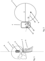
- Fig. 1 is a perspective view of a head 2 of a user schematically showing an ear-worn, sound generating object 4. More specifically, a skull and a portion of a spine 9 including cervical vertebrae is illustrated. Further, a center axis 6 of the wearer's head and a corresponding head pivot point 5 are shown. As defined above, the center axis 6 is an axis substantially perpendicular to a horizontal, ground plane, and it intersects the head pivot point 5, i.e. a point around which the head rotates side to side. As it may be seen, the head pivot point 5 is positioned at an interface of the skull and the topmost vertebrae 7, also called atlas. The ear-worn, sound generating object 4 is also shown.
- said object may be chosen from the group comprising hearing instruments, earpads belonging to a headphone, ear pieces being part of a headset or hearables. Relevant structural features of the sound generating object will be more thoroughly described in conjunction with Fig. 2 .
- Fig. 2 is a close-up of an accelerometer configuration according to an embodiment of the present invention.
- the configuration is shown in top view and the center axis extends perpendicularly to the plane of the paper.
- a sound generating object here a hearing aid, is schematically shown.
- the hearing aid comprises a first and a second accelerometers, the respective accelerometer being arranged to measure at least an acceleration component (a1, a2) intersecting at a substantially right angle a center axis of the wearer's head.
- the two accelerometers are so arranged that a straight line that intersects the center axis of the wearer's head at a substantially right angle crosses the two accelerometers.
- the accelerometers are spaced by a known distance ( ⁇ r). In hearing aids, this distance is, due to spatial constraints, typically below 10 mm, preferably between 5 and 8 mm.
- the accelerations measured with the two accelerometers are a meas 1 ( t ) and a meas 2 ( t ) and the distance ( ⁇ r) is a known distance.
- the distances to be calculated are, firstly, a distance R 1 from the center axis of the head to a first accelerometer and the corresponding distance R 2 to a second accelerometer, where R 2 > R 1 , i.e. R 1 is positioned closer to the center axis than R 2 .
- R 2 and R 1 are calculated in the following manner once the user starts to rotate his head:
- the magnitude of the angular acceleration originating from the head rotation is a 0 at a given time t 0 .
- R 1 ⁇ r a meas 2 a meas 1 ⁇ 1
- an automatic adjustment of the distance (D) between the ears of the wearer may be achieved.
- no involvement of the user is required in order to handily and accurately determine the ear-to-ear distance.
- said method is due to its inherent simplicity easily integrated in the existing software.
- the effect conferred by the inventive method is the improved fidelity with respect to presentation of the virtual (3D) audio signals generated by the sound generating object.
- more advanced beamformers may be employed.
- estimation of the direction of arrival (DOA) of the speech signal could be significantly improved when the head size is accurately determined.
- the distance (D) is determined as a function of time and averaged over a time interval.
- the length of the time interval is at least 60 seconds. In certain applications, even longer time intervals may be used.
- hearing aids carrying two accelerometers are known in the art.
- such a set-up is disclosed in WO9914985 attempting to reduce vibrations in the miniature hearing aids.
- two accelerometers are arranged in a hearing aid of the completely-in-the-canal-type (CIC).
- the accelerometers are so positioned within the hearing aid so that they are physically secured to its housing since they measure vibrations that arise due to feedback loop in the hearing aid. Otherwise, their position in the hearing aid is completely arbitrary.
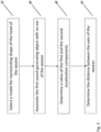
- Fig. 3 is a flow chart illustrating a method for determining a distance (D) between ears of a wearer of a sound generating object, according to one embodiment of the present invention.
- the method may be performed in a device such a hearing aid, hearable or a headphone.
- the applications where accelerometers are integrated in hearing aids are experiencing increased interest from the industry.
- the method comprises to select 20 a model for representing shape of the head of the wearer of the sound generating object means for allowing the wearer of the sound generating object to select a model for representing shape of the head so as to obtain a center axis of the wearer's head.
- the shape of the head is approximated by a well-known geometric body, e.g.
- the method comprises to associate 30 the first sound generating object with an ear of the wearer, wherein the first sound generating object comprises a first accelerometer and a second accelerometer, the respective accelerometers being arranged to measure at least an acceleration component (a1, a2) intersecting at a substantially right angle a center axis of the wearer's head, said two accelerometers being spaced by a known distance ( ⁇ r).
- the first sound generating object comprises a first accelerometer and a second accelerometer, the respective accelerometers being arranged to measure at least an acceleration component (a1, a2) intersecting at a substantially right angle a center axis of the wearer's head, said two accelerometers being spaced by a known distance ( ⁇ r).
- the method further comprises to, when the head of the wearer is in motion, determine 40, by means of the first accelerometer, a value of the first acceleration component (a1) intersecting at a substantially right angle a center axis of the wearer's head and, by means of the second accelerometer, a value of the second acceleration component (a2) intersecting at a substantially right angle a center axis of the wearer's head.
- the method also comprises to, on the basis of the obtained values of the acceleration components (a1, a2), determine 50 the distance (D) between the ears of the wearer.
Landscapes
- Physics & Mathematics (AREA)
- Engineering & Computer Science (AREA)
- Acoustics & Sound (AREA)
- Signal Processing (AREA)
- Stereophonic System (AREA)
- Length Measuring Devices With Unspecified Measuring Means (AREA)
- Headphones And Earphones (AREA)
Claims (8)
- Verfahren zum Bestimmen eines Abstands (D) zwischen Ohren eines Trägers eines schallerzeugenden Objekts (4), wobei das Verfahren umfasst:Auswählen (20) eines Modells zum Darstellen der Form des Kopfes (2) des Trägers des schallerzeugenden Objekts (4), um eine Mittelachse (6) des Kopfes des Trägers zu erhalten, wobei die Mittelachse eine im Wesentlichen senkrechte Achse ist zu einer horizontalen Grundebene und schneidet einen Kopfdrehpunkt des Kopfes des Trägers,Zuordnen (30) des ersten schallerzeugenden Objekts (4) zu einem Ohr des Trägers, wobei das erste schallerzeugende Objekt (4) einen ersten Beschleunigungsmesser (10) und einen zweiten Beschleunigungsmesser (12) umfasst, wobei die jeweiligen Beschleunigungsmesser (10, 12) angeordnet ist, um mindestens eine Beschleunigungskomponente (a1, a2) zu messen, die die Mittelachse (6) des Kopfes des Trägers in einem im Wesentlichen rechten Winkel schneidet, wobei der erste und der zweite Beschleunigungsmesser (10, 12) so angeordnet sind, dass sie eine gerade Linie bilden (14), der die Mittelachse (6) des Kopfes des Trägers in einem im wesentlichen rechten Winkel schneidet, kreuzt den ersten und den zweiten Beschleunigungsmesser (10, 12), so dass die Beschleunigungskomponenten (a1, a2) die gleiche Richtung haben, der erste und der zweite Beschleunigungsmesser (10, 12), die um einen bekannten Abstand (Δr) beabstandet sind,wenn der Kopf (2) des Trägers in Bewegung ist, Bestimmen (40) mittels des ersten Beschleunigungsmessers (10) eines Werts einer ersten Beschleunigungskomponente (a1) und mittels des zweiten Beschleunigungsmessers (12), ein Wert einer zweiten Beschleunigungskomponente (a2),Bestimmen (50) des Abstands (D) zwischen den Ohren des Trägers auf der Grundlage des Modells, der erhaltenen Werte der ersten und zweiten Beschleunigungskomponenten (a1, a2) und des bekannten Abstands zwischen dem ersten Beschleunigungsmesser und dem zweiten Beschleunigungsmesser.
- Verfahren nach Anspruch 1, dadurch gekennzeichnet, dass die Distanz (D) zeitabhängig bestimmt und über ein Zeitintervall gemittelt wird.
- Verfahren nach Anspruch 2, wobei die Länge des Zeitintervalls mindestens 60 Sekunden beträgt.
- Ein erstes schallerzeugendes Objekt (4), das, um an einem Ohr eines Trägers getragen zu werden konfiguriert ist, wobei das erste schallerzeugende Objekt (4) umfasst:Mittel, die es dem Träger des schallerzeugenden Objekts ermöglichen, ein Modell zum Darstellen der Form des Kopfs (2) auszuwählen, um eine Mittelachse (6) des Kopfs des Trägers zu erhalten, wobei die Mittelachse eine Achse ist, die im Wesentlichen senkrecht zu einer Horizontalen ist, Grundebene und einen Kopfdrehpunkt des Kopfes des Trägers schneidend,einen ersten Beschleunigungsmesser (10) und einen zweiten Beschleunigungsmesser (12), wobei die jeweiligen Beschleunigungsmesser so angeordnet sind, dass sie mindestens eine Beschleunigungskomponente (a1, a2) messen, die die Mittelachse des Kopfes (2) des Trägers in einem im Wesentlichen rechten Winkel schneidet, wobei die erste und zweite Beschleunigungsmesser (10, 12) so angeordnet sind, dass eine gerade Linie (14), die die Mittelachse (6) des Kopfes des Trägers in einem im Wesentlichen rechten Winkel schneidet, den ersten und zweiten Beschleunigungsmesser (10, 12) schneidet, so dass die Beschleunigungskomponenten (a1, a2) haben die gleiche Richtung, wobei der erste und der zweite Beschleunigungsmesser (10, 12) um einen bekannten Abstand (Δr) beabstandet sind,wobei der erste Beschleunigungsmesser (10) mit Mitteln zum Bestimmen eines Werts einer ersten Beschleunigungskomponente (a1) versehen ist und der zweite Beschleunigungsmesser (12) mit Mitteln zum Bestimmen eines Werts einer zweiten Beschleunigungskomponente (a2) versehen ist, undwobei das erste Schallerzeugungsobjekt (4) mit Mitteln zum Bestimmen der erhaltenen Werte der ersten und zweiten Beschleunigungskomponenten (a1, a2) und des bekannten Abstands zwischen dem ersten Beschleunigungsmesser und dem zweiten auf der Grundlage des Modells versehen ist Beschleunigungsmesser, ein Abstand (D) zwischen den Ohren des Trägers.
- Erstes schallerzeugendes Objekt (4) nach Anspruch 4, wobei das erste schallerzeugende Objekt ein Hörinstrument ist.
- Erstes schallerzeugendes Objekt (4) nach Anspruch 4, wobei das erste schallerzeugende Objekt von einem zu einem Kopfhörer gehörenden Ohrpolster umschlossen ist.
- Erstes schallerzeugendes Objekt (4) nach Anspruch 4, wobei das erste schallerzeugende Objekt ein Ohrstück ist, das Teil eines Headsets ist.
- Erstes schallerzeugendes Objekt (4) nach Anspruch 4, wobei das erste schallerzeugende Objekt ein Hörobjekt ist.
Applications Claiming Priority (2)
| Application Number | Priority Date | Filing Date | Title |
|---|---|---|---|
| EP17171286 | 2017-05-16 | ||
| PCT/EP2018/062817 WO2018210974A1 (en) | 2017-05-16 | 2018-05-16 | A method for determining distance between ears of a wearer of a sound generating object and an ear-worn, sound generating object |
Publications (2)
| Publication Number | Publication Date |
|---|---|
| EP3625976A1 EP3625976A1 (de) | 2020-03-25 |
| EP3625976B1 true EP3625976B1 (de) | 2023-08-09 |
Family
ID=58745046
Family Applications (1)
| Application Number | Title | Priority Date | Filing Date |
|---|---|---|---|
| EP18723040.4A Active EP3625976B1 (de) | 2017-05-16 | 2018-05-16 | Verfahren zur bestimmung der entfernung zwischen ohren eines trägers eines schallerzeugungsobjekts und einem im ohr getragenen schallerzeugungsobjekt |
Country Status (6)
| Country | Link |
|---|---|
| US (2) | US10911886B2 (de) |
| EP (1) | EP3625976B1 (de) |
| JP (1) | JP2020520198A (de) |
| CN (1) | CN110741657B (de) |
| DK (1) | DK3625976T3 (de) |
| WO (1) | WO2018210974A1 (de) |
Families Citing this family (3)
| Publication number | Priority date | Publication date | Assignee | Title |
|---|---|---|---|---|
| CN110741657B (zh) | 2017-05-16 | 2021-06-29 | 大北欧听力公司 | 用于确定声音生成物体的佩戴者的耳部之间的距离的方法以及耳戴式声音生成物体 |
| US10845379B1 (en) * | 2017-08-10 | 2020-11-24 | Mcube, Inc. | Low power rotational detection methods and apparatus |
| US20240292148A1 (en) * | 2021-07-20 | 2024-08-29 | Panasonic Intellectual Property Management Co., Ltd. | Headset and method for controlling directivity of call microphone |
Family Cites Families (18)
| Publication number | Priority date | Publication date | Assignee | Title |
|---|---|---|---|---|
| JP2939105B2 (ja) * | 1993-12-27 | 1999-08-25 | シャープ株式会社 | 3次元音場制御用ステレオヘッドホン装置 |
| JP3395807B2 (ja) * | 1994-09-07 | 2003-04-14 | 日本電信電話株式会社 | ステレオ音響再生装置 |
| JP3388478B2 (ja) * | 1994-09-07 | 2003-03-24 | 日本電信電話株式会社 | ヘッドホン |
| WO1999014985A1 (en) | 1997-09-17 | 1999-03-25 | Siemens Hearing Instruments, Inc. | High-gain, feedback-resistant cic hearing aid |
| TR201908933T4 (tr) * | 2009-02-13 | 2019-07-22 | Koninklijke Philips Nv | Mobil uygulamalar için baş hareketi izleme. |
| CN101835072B (zh) * | 2010-04-06 | 2011-11-23 | 瑞声声学科技(深圳)有限公司 | 虚拟环绕声处理方法 |
| US9332372B2 (en) * | 2010-06-07 | 2016-05-03 | International Business Machines Corporation | Virtual spatial sound scape |
| WO2012164346A1 (en) * | 2011-05-27 | 2012-12-06 | Sony Ericsson Mobile Communications Ab | Head-related transfer function (hrtf) selection or adaptation based on head size |
| CN103697859A (zh) * | 2012-09-27 | 2014-04-02 | 上海西门子医疗器械有限公司 | 一种用于测量倾斜角的测量装置和一种医疗设备 |
| EP2890161A1 (de) | 2013-12-30 | 2015-07-01 | GN Store Nord A/S | Anordnung und Verfahren zur Bestimmung einer Entfernung zwischen zwei schallerzeugenden Objekten |
| KR102433613B1 (ko) * | 2014-12-04 | 2022-08-19 | 가우디오랩 주식회사 | 개인 특징을 반영한 바이노럴 오디오 신호 처리 방법 및 장치 |
| CN107996028A (zh) * | 2015-03-10 | 2018-05-04 | Ossic公司 | 校准听音装置 |
| JP6642989B2 (ja) * | 2015-07-06 | 2020-02-12 | キヤノン株式会社 | 制御装置、制御方法及びプログラム |
| US10117012B2 (en) * | 2015-09-28 | 2018-10-30 | Apple Inc. | Wireless ear buds with proximity sensors |
| US9955279B2 (en) * | 2016-05-11 | 2018-04-24 | Ossic Corporation | Systems and methods of calibrating earphones |
| CN106162499B (zh) * | 2016-07-04 | 2018-02-23 | 大连理工大学 | 一种头相关传递函数的个性化方法及系统 |
| US10638250B2 (en) * | 2016-09-23 | 2020-04-28 | Apple Inc. | Systems and methods for determining estimated head orientation and position with ear pieces |
| CN110741657B (zh) * | 2017-05-16 | 2021-06-29 | 大北欧听力公司 | 用于确定声音生成物体的佩戴者的耳部之间的距离的方法以及耳戴式声音生成物体 |
-
2018
- 2018-05-16 CN CN201880039493.6A patent/CN110741657B/zh active Active
- 2018-05-16 EP EP18723040.4A patent/EP3625976B1/de active Active
- 2018-05-16 WO PCT/EP2018/062817 patent/WO2018210974A1/en not_active Ceased
- 2018-05-16 DK DK18723040.4T patent/DK3625976T3/da active
- 2018-05-16 JP JP2019563273A patent/JP2020520198A/ja active Pending
-
2019
- 2019-11-07 US US16/677,627 patent/US10911886B2/en active Active
-
2021
- 2021-02-01 US US17/163,572 patent/US11330390B2/en active Active
Also Published As
| Publication number | Publication date |
|---|---|
| DK3625976T3 (da) | 2023-10-23 |
| US10911886B2 (en) | 2021-02-02 |
| EP3625976A1 (de) | 2020-03-25 |
| US20200077223A1 (en) | 2020-03-05 |
| CN110741657A (zh) | 2020-01-31 |
| JP2020520198A (ja) | 2020-07-02 |
| WO2018210974A1 (en) | 2018-11-22 |
| US11330390B2 (en) | 2022-05-10 |
| CN110741657B (zh) | 2021-06-29 |
| US20210152971A1 (en) | 2021-05-20 |
Similar Documents
| Publication | Publication Date | Title |
|---|---|---|
| US9848273B1 (en) | Head related transfer function individualization for hearing device | |
| US11832082B2 (en) | Self-calibrating microphone and loudspeaker arrays for wearable audio devices | |
| JP5894634B2 (ja) | 個人ごとのhrtfの決定 | |
| US7561707B2 (en) | Hearing aid system | |
| CN107690110B (zh) | 用于操作可穿戴式扬声器设备的系统和方法 | |
| US11330390B2 (en) | Method for determining distance between ears of a wearer of a sound generating object and an ear-worn, sound generating object | |
| CN112544089A (zh) | 提供具有空间背景的音频的麦克风设备 | |
| WO2014208085A1 (ja) | 測定装置及び測定システム | |
| CN115150716B (zh) | 基于设备位置确定音频滤波器的音频系统和方法 | |
| US10924837B2 (en) | Acoustic device | |
| JP2016158212A (ja) | 測定システム及び測定方法 | |
| WO2025201282A1 (zh) | 耳机左右声道匹配方法、装置、耳夹式耳机和存储介质 | |
| EP2273800A1 (de) | Hörgerät mit einer virtuellen Schallquelle | |
| US12501230B2 (en) | Hearing device | |
| Wersényi | Comparison of Transfer Functions of Open Ear Canal Headsets Measured on a Dummy-Head and a Human Head | |
| CN109963232A (zh) | 音频信号播放装置及对应的音频信号处理方法 | |
| JP2020086143A (ja) | 情報処理システム、情報処理方法、測定システム、及びプログラム | |
| CN111213390A (zh) | 改进的声音转换器 |
Legal Events
| Date | Code | Title | Description |
|---|---|---|---|
| STAA | Information on the status of an ep patent application or granted ep patent |
Free format text: STATUS: UNKNOWN |
|
| STAA | Information on the status of an ep patent application or granted ep patent |
Free format text: STATUS: THE INTERNATIONAL PUBLICATION HAS BEEN MADE |
|
| PUAI | Public reference made under article 153(3) epc to a published international application that has entered the european phase |
Free format text: ORIGINAL CODE: 0009012 |
|
| STAA | Information on the status of an ep patent application or granted ep patent |
Free format text: STATUS: REQUEST FOR EXAMINATION WAS MADE |
|
| 17P | Request for examination filed |
Effective date: 20191118 |
|
| AK | Designated contracting states |
Kind code of ref document: A1 Designated state(s): AL AT BE BG CH CY CZ DE DK EE ES FI FR GB GR HR HU IE IS IT LI LT LU LV MC MK MT NL NO PL PT RO RS SE SI SK SM TR |
|
| AX | Request for extension of the european patent |
Extension state: BA ME |
|
| DAV | Request for validation of the european patent (deleted) | ||
| DAX | Request for extension of the european patent (deleted) | ||
| STAA | Information on the status of an ep patent application or granted ep patent |
Free format text: STATUS: EXAMINATION IS IN PROGRESS |
|
| 17Q | First examination report despatched |
Effective date: 20210324 |
|
| GRAP | Despatch of communication of intention to grant a patent |
Free format text: ORIGINAL CODE: EPIDOSNIGR1 |
|
| STAA | Information on the status of an ep patent application or granted ep patent |
Free format text: STATUS: GRANT OF PATENT IS INTENDED |
|
| INTG | Intention to grant announced |
Effective date: 20221125 |
|
| GRAS | Grant fee paid |
Free format text: ORIGINAL CODE: EPIDOSNIGR3 |
|
| GRAA | (expected) grant |
Free format text: ORIGINAL CODE: 0009210 |
|
| STAA | Information on the status of an ep patent application or granted ep patent |
Free format text: STATUS: THE PATENT HAS BEEN GRANTED |
|
| AK | Designated contracting states |
Kind code of ref document: B1 Designated state(s): AL AT BE BG CH CY CZ DE DK EE ES FI FR GB GR HR HU IE IS IT LI LT LU LV MC MK MT NL NO PL PT RO RS SE SI SK SM TR |
|
| REG | Reference to a national code |
Ref country code: GB Ref legal event code: FG4D |
|
| REG | Reference to a national code |
Ref country code: CH Ref legal event code: EP |
|
| REG | Reference to a national code |
Ref country code: IE Ref legal event code: FG4D |
|
| REG | Reference to a national code |
Ref country code: DE Ref legal event code: R096 Ref document number: 602018054967 Country of ref document: DE |
|
| REG | Reference to a national code |
Ref country code: DK Ref legal event code: T3 Effective date: 20231017 |
|
| REG | Reference to a national code |
Ref country code: LT Ref legal event code: MG9D |
|
| REG | Reference to a national code |
Ref country code: NL Ref legal event code: MP Effective date: 20230809 |
|
| REG | Reference to a national code |
Ref country code: AT Ref legal event code: MK05 Ref document number: 1598862 Country of ref document: AT Kind code of ref document: T Effective date: 20230809 |
|
| PG25 | Lapsed in a contracting state [announced via postgrant information from national office to epo] |
Ref country code: GR Free format text: LAPSE BECAUSE OF FAILURE TO SUBMIT A TRANSLATION OF THE DESCRIPTION OR TO PAY THE FEE WITHIN THE PRESCRIBED TIME-LIMIT Effective date: 20231110 |
|
| PG25 | Lapsed in a contracting state [announced via postgrant information from national office to epo] |
Ref country code: IS Free format text: LAPSE BECAUSE OF FAILURE TO SUBMIT A TRANSLATION OF THE DESCRIPTION OR TO PAY THE FEE WITHIN THE PRESCRIBED TIME-LIMIT Effective date: 20231209 |
|
| PG25 | Lapsed in a contracting state [announced via postgrant information from national office to epo] |
Ref country code: SE Free format text: LAPSE BECAUSE OF FAILURE TO SUBMIT A TRANSLATION OF THE DESCRIPTION OR TO PAY THE FEE WITHIN THE PRESCRIBED TIME-LIMIT Effective date: 20230809 Ref country code: RS Free format text: LAPSE BECAUSE OF FAILURE TO SUBMIT A TRANSLATION OF THE DESCRIPTION OR TO PAY THE FEE WITHIN THE PRESCRIBED TIME-LIMIT Effective date: 20230809 Ref country code: PT Free format text: LAPSE BECAUSE OF FAILURE TO SUBMIT A TRANSLATION OF THE DESCRIPTION OR TO PAY THE FEE WITHIN THE PRESCRIBED TIME-LIMIT Effective date: 20231211 Ref country code: NO Free format text: LAPSE BECAUSE OF FAILURE TO SUBMIT A TRANSLATION OF THE DESCRIPTION OR TO PAY THE FEE WITHIN THE PRESCRIBED TIME-LIMIT Effective date: 20231109 Ref country code: NL Free format text: LAPSE BECAUSE OF FAILURE TO SUBMIT A TRANSLATION OF THE DESCRIPTION OR TO PAY THE FEE WITHIN THE PRESCRIBED TIME-LIMIT Effective date: 20230809 Ref country code: LV Free format text: LAPSE BECAUSE OF FAILURE TO SUBMIT A TRANSLATION OF THE DESCRIPTION OR TO PAY THE FEE WITHIN THE PRESCRIBED TIME-LIMIT Effective date: 20230809 Ref country code: LT Free format text: LAPSE BECAUSE OF FAILURE TO SUBMIT A TRANSLATION OF THE DESCRIPTION OR TO PAY THE FEE WITHIN THE PRESCRIBED TIME-LIMIT Effective date: 20230809 Ref country code: IS Free format text: LAPSE BECAUSE OF FAILURE TO SUBMIT A TRANSLATION OF THE DESCRIPTION OR TO PAY THE FEE WITHIN THE PRESCRIBED TIME-LIMIT Effective date: 20231209 Ref country code: HR Free format text: LAPSE BECAUSE OF FAILURE TO SUBMIT A TRANSLATION OF THE DESCRIPTION OR TO PAY THE FEE WITHIN THE PRESCRIBED TIME-LIMIT Effective date: 20230809 Ref country code: GR Free format text: LAPSE BECAUSE OF FAILURE TO SUBMIT A TRANSLATION OF THE DESCRIPTION OR TO PAY THE FEE WITHIN THE PRESCRIBED TIME-LIMIT Effective date: 20231110 Ref country code: FI Free format text: LAPSE BECAUSE OF FAILURE TO SUBMIT A TRANSLATION OF THE DESCRIPTION OR TO PAY THE FEE WITHIN THE PRESCRIBED TIME-LIMIT Effective date: 20230809 Ref country code: AT Free format text: LAPSE BECAUSE OF FAILURE TO SUBMIT A TRANSLATION OF THE DESCRIPTION OR TO PAY THE FEE WITHIN THE PRESCRIBED TIME-LIMIT Effective date: 20230809 |
|
| PG25 | Lapsed in a contracting state [announced via postgrant information from national office to epo] |
Ref country code: PL Free format text: LAPSE BECAUSE OF FAILURE TO SUBMIT A TRANSLATION OF THE DESCRIPTION OR TO PAY THE FEE WITHIN THE PRESCRIBED TIME-LIMIT Effective date: 20230809 |
|
| PG25 | Lapsed in a contracting state [announced via postgrant information from national office to epo] |
Ref country code: ES Free format text: LAPSE BECAUSE OF FAILURE TO SUBMIT A TRANSLATION OF THE DESCRIPTION OR TO PAY THE FEE WITHIN THE PRESCRIBED TIME-LIMIT Effective date: 20230809 |
|
| PG25 | Lapsed in a contracting state [announced via postgrant information from national office to epo] |
Ref country code: SM Free format text: LAPSE BECAUSE OF FAILURE TO SUBMIT A TRANSLATION OF THE DESCRIPTION OR TO PAY THE FEE WITHIN THE PRESCRIBED TIME-LIMIT Effective date: 20230809 Ref country code: RO Free format text: LAPSE BECAUSE OF FAILURE TO SUBMIT A TRANSLATION OF THE DESCRIPTION OR TO PAY THE FEE WITHIN THE PRESCRIBED TIME-LIMIT Effective date: 20230809 Ref country code: ES Free format text: LAPSE BECAUSE OF FAILURE TO SUBMIT A TRANSLATION OF THE DESCRIPTION OR TO PAY THE FEE WITHIN THE PRESCRIBED TIME-LIMIT Effective date: 20230809 Ref country code: EE Free format text: LAPSE BECAUSE OF FAILURE TO SUBMIT A TRANSLATION OF THE DESCRIPTION OR TO PAY THE FEE WITHIN THE PRESCRIBED TIME-LIMIT Effective date: 20230809 Ref country code: CZ Free format text: LAPSE BECAUSE OF FAILURE TO SUBMIT A TRANSLATION OF THE DESCRIPTION OR TO PAY THE FEE WITHIN THE PRESCRIBED TIME-LIMIT Effective date: 20230809 Ref country code: SK Free format text: LAPSE BECAUSE OF FAILURE TO SUBMIT A TRANSLATION OF THE DESCRIPTION OR TO PAY THE FEE WITHIN THE PRESCRIBED TIME-LIMIT Effective date: 20230809 |
|
| REG | Reference to a national code |
Ref country code: DE Ref legal event code: R097 Ref document number: 602018054967 Country of ref document: DE |
|
| PG25 | Lapsed in a contracting state [announced via postgrant information from national office to epo] |
Ref country code: IT Free format text: LAPSE BECAUSE OF FAILURE TO SUBMIT A TRANSLATION OF THE DESCRIPTION OR TO PAY THE FEE WITHIN THE PRESCRIBED TIME-LIMIT Effective date: 20230809 |
|
| PLBE | No opposition filed within time limit |
Free format text: ORIGINAL CODE: 0009261 |
|
| STAA | Information on the status of an ep patent application or granted ep patent |
Free format text: STATUS: NO OPPOSITION FILED WITHIN TIME LIMIT |
|
| 26N | No opposition filed |
Effective date: 20240513 |
|
| PG25 | Lapsed in a contracting state [announced via postgrant information from national office to epo] |
Ref country code: SI Free format text: LAPSE BECAUSE OF FAILURE TO SUBMIT A TRANSLATION OF THE DESCRIPTION OR TO PAY THE FEE WITHIN THE PRESCRIBED TIME-LIMIT Effective date: 20230809 |
|
| PG25 | Lapsed in a contracting state [announced via postgrant information from national office to epo] |
Ref country code: BG Free format text: LAPSE BECAUSE OF FAILURE TO SUBMIT A TRANSLATION OF THE DESCRIPTION OR TO PAY THE FEE WITHIN THE PRESCRIBED TIME-LIMIT Effective date: 20230809 |
|
| PG25 | Lapsed in a contracting state [announced via postgrant information from national office to epo] |
Ref country code: BG Free format text: LAPSE BECAUSE OF FAILURE TO SUBMIT A TRANSLATION OF THE DESCRIPTION OR TO PAY THE FEE WITHIN THE PRESCRIBED TIME-LIMIT Effective date: 20230809 |
|
| PG25 | Lapsed in a contracting state [announced via postgrant information from national office to epo] |
Ref country code: MC Free format text: LAPSE BECAUSE OF FAILURE TO SUBMIT A TRANSLATION OF THE DESCRIPTION OR TO PAY THE FEE WITHIN THE PRESCRIBED TIME-LIMIT Effective date: 20230809 |
|
| PG25 | Lapsed in a contracting state [announced via postgrant information from national office to epo] |
Ref country code: LU Free format text: LAPSE BECAUSE OF NON-PAYMENT OF DUE FEES Effective date: 20240516 |
|
| PG25 | Lapsed in a contracting state [announced via postgrant information from national office to epo] |
Ref country code: MC Free format text: LAPSE BECAUSE OF FAILURE TO SUBMIT A TRANSLATION OF THE DESCRIPTION OR TO PAY THE FEE WITHIN THE PRESCRIBED TIME-LIMIT Effective date: 20230809 Ref country code: LU Free format text: LAPSE BECAUSE OF NON-PAYMENT OF DUE FEES Effective date: 20240516 |
|
| REG | Reference to a national code |
Ref country code: BE Ref legal event code: MM Effective date: 20240531 |
|
| PG25 | Lapsed in a contracting state [announced via postgrant information from national office to epo] |
Ref country code: IE Free format text: LAPSE BECAUSE OF NON-PAYMENT OF DUE FEES Effective date: 20240516 |
|
| PG25 | Lapsed in a contracting state [announced via postgrant information from national office to epo] |
Ref country code: BE Free format text: LAPSE BECAUSE OF NON-PAYMENT OF DUE FEES Effective date: 20240531 |
|
| PGFP | Annual fee paid to national office [announced via postgrant information from national office to epo] |
Ref country code: DE Payment date: 20250520 Year of fee payment: 8 |
|
| PGFP | Annual fee paid to national office [announced via postgrant information from national office to epo] |
Ref country code: DK Payment date: 20250522 Year of fee payment: 8 |
|
| PGFP | Annual fee paid to national office [announced via postgrant information from national office to epo] |
Ref country code: FR Payment date: 20250516 Year of fee payment: 8 |
|
| PGFP | Annual fee paid to national office [announced via postgrant information from national office to epo] |
Ref country code: CH Payment date: 20250601 Year of fee payment: 8 |
|
| PG25 | Lapsed in a contracting state [announced via postgrant information from national office to epo] |
Ref country code: CY Free format text: LAPSE BECAUSE OF FAILURE TO SUBMIT A TRANSLATION OF THE DESCRIPTION OR TO PAY THE FEE WITHIN THE PRESCRIBED TIME-LIMIT; INVALID AB INITIO Effective date: 20180516 |
|
| PG25 | Lapsed in a contracting state [announced via postgrant information from national office to epo] |
Ref country code: HU Free format text: LAPSE BECAUSE OF FAILURE TO SUBMIT A TRANSLATION OF THE DESCRIPTION OR TO PAY THE FEE WITHIN THE PRESCRIBED TIME-LIMIT; INVALID AB INITIO Effective date: 20180516 |
|
| PGFP | Annual fee paid to national office [announced via postgrant information from national office to epo] |
Ref country code: GB Payment date: 20260317 Year of fee payment: 9 |