EP3626008B1 - Auf berechtigung basierende uplink-übertragung in einem unlizenzierten band - Google Patents
Auf berechtigung basierende uplink-übertragung in einem unlizenzierten band Download PDFInfo
- Publication number
- EP3626008B1 EP3626008B1 EP18809565.7A EP18809565A EP3626008B1 EP 3626008 B1 EP3626008 B1 EP 3626008B1 EP 18809565 A EP18809565 A EP 18809565A EP 3626008 B1 EP3626008 B1 EP 3626008B1
- Authority
- EP
- European Patent Office
- Prior art keywords
- uplink transmission
- frequency resource
- start point
- allocated
- uplink
- Prior art date
- Legal status (The legal status is an assumption and is not a legal conclusion. Google has not performed a legal analysis and makes no representation as to the accuracy of the status listed.)
- Active
Links
Images








Classifications
-
- H—ELECTRICITY
- H04—ELECTRIC COMMUNICATION TECHNIQUE
- H04W—WIRELESS COMMUNICATION NETWORKS
- H04W72/00—Local resource management
- H04W72/04—Wireless resource allocation
-
- H—ELECTRICITY
- H04—ELECTRIC COMMUNICATION TECHNIQUE
- H04W—WIRELESS COMMUNICATION NETWORKS
- H04W72/00—Local resource management
- H04W72/12—Wireless traffic scheduling
- H04W72/1263—Mapping of traffic onto schedule, e.g. scheduled allocation or multiplexing of flows
- H04W72/1268—Mapping of traffic onto schedule, e.g. scheduled allocation or multiplexing of flows of uplink data flows
-
- H—ELECTRICITY
- H04—ELECTRIC COMMUNICATION TECHNIQUE
- H04W—WIRELESS COMMUNICATION NETWORKS
- H04W72/00—Local resource management
- H04W72/20—Control channels or signalling for resource management
- H04W72/23—Control channels or signalling for resource management in the downlink direction of a wireless link, i.e. towards a terminal
-
- H—ELECTRICITY
- H04—ELECTRIC COMMUNICATION TECHNIQUE
- H04W—WIRELESS COMMUNICATION NETWORKS
- H04W74/00—Wireless channel access
- H04W74/08—Non-scheduled access, e.g. ALOHA
- H04W74/0808—Non-scheduled access, e.g. ALOHA using carrier sensing, e.g. carrier sense multiple access [CSMA]
Definitions
- the present disclosure relates generally to wireless communications and, in particular, to grant-based uplink transmission in an unlicensed band.
- an electronic device such as a user equipment (UE) wirelessly communicates with a Transmission and Receive Point (TRP), termed “base station”, to send data to the ED and/or receive data from the ED.
- TRP Transmission and Receive Point
- a wireless communication from an ED to a base station is referred to as an uplink communication.
- a wireless communication from a base station to an ED is referred to as a downlink communication.
- an ED may wirelessly transmit data to a base station in an uplink transmission at a particular frequency and during a particular time slot.
- the frequency and time slot used is an example of a physical communication resource.
- the required transmission control parameters are typically communicated via a Physical Uplink Control Channel (PUCCH) and/or Physical Downlink Control Channel (PDCCH).
- PUCCH Physical Uplink Control Channel
- PDCH Physical Downlink Control Channel
- Some modes of communication may enable communications with an ED over an unlicensed spectrum band, or over different spectrum bands (e.g., an unlicensed spectrum band and a licensed spectrum band) of a wireless network.
- spectrum bands e.g., an unlicensed spectrum band and a licensed spectrum band
- MBB mobile broadband
- uplink transmissions may be transmitted over an unlicensed spectrum band. Accordingly, efficient and fair mechanisms for grant-based uplink transmissions in the unlicensed spectrum may be desirable.
- Document, 3GPP TSG RAN WG1 Meeting #89 R1-1709160 discloses proposals for supporting more starting or ending positions in an uplink subframe allowed for License Assisted Access.
- the proposals comprise adding a 2 nd slot boundary as an additional uplink starting position, so that if an LBT for an uplink transmission fails, a terminal device can start another LBT from the 2 nd slot boundary for the uplink transmission.
- this 2 nd slot boundary may be configurable by higher layer signalling from a base station.
- the present invention is defined by a method for an Electronic Device (ED) in a wireless network according to independent claim 1, and an ED according to independent claim 14. Additional features of the invention are provided in the dependent claims.
- ED Electronic Device
- the present disclosure provides a method for an ED in a wireless network.
- the method according to the first aspect includes receiving an uplink grant message from a base station, the uplink grant message indicating a time-frequency resource allocated to the ED for uplink transmission in an unlicensed spectrum band.
- the method according to the first aspect further includes performing a first listen-before-talk (LBT) operation for the allocated time-frequency resource, and performing a second LBT operation within the allocated time-frequency resource if the first LBT operation fails.
- LBT listen-before-talk
- the method further includes transmitting an uplink transmission within a remaining portion of the allocated time-frequency resource in response to the second LBT operation succeeding.
- the uplink transmission may include an activation signal to indicate a start of the uplink transmission and uplink payload data.
- the ED is allocated a subset of subcarriers of a component carrier (CC) bandwidth;
- the second LBT operation is a narrowband LBT operation that is based on energy measured on the allocated subset of subcarriers during one or more OFDM symbol intervals immediately preceding a start point within the allocated time-frequency resource; and transmitting the uplink transmission comprises transmitting the uplink transmission on the allocated subset of subcarriers within the remaining portion of the allocated time-frequency resource.
- a bandwidth of the narrowband LBT operation performed by the ED is narrower than a full channel bandwidth of the CC or bandwidth part in which an uplink resource is scheduled.
- the second LBT operation is performed at a start time based on a start point configuration within the allocated time-frequency resource.
- the start point configuration indicates the configuration of a plurality of possible start points of uplink transmission within a subframe.
- each start point is either at an OFDM symbol boundary or midway between adjacent OFDM symbol boundaries, within the allocated time-frequency resource.
- the method further includes receiving, from the base station, information indicating the start point configuration.
- the activation signal is a demodulation reference signal (DMRS).
- DMRS demodulation reference signal
- transmitting an uplink transmission within the remaining portion of the allocated time-frequency resource comprises transmitting the uplink transmission with one or more blanking intervals within the remaining portion of the allocated time-frequency resource based on the start point configuration.
- performing a second LBT operation within the allocated time-frequency resource comprises performing an LBT operation at each of a plurality of start times based on the start point configuration until one of the LBT operations succeeds.
- the second LBT operation is performed during one or more orthogonal frequency division multiplexing (OFDM) symbol intervals immediately preceding a start point within the allocated time-frequency resource.
- OFDM orthogonal frequency division multiplexing
- the method further includes, in response to the second LBT operation succeeding, transmitting a reservation signal between the start point of uplink transmission and the closest OFDM symbol boundary after the start point.
- the reservation signal includes a cyclic prefix extension of the following OFDM symbol.
- transmitting an uplink transmission within a remaining portion of the allocated time-frequency resource comprises transmitting the activation signal at a start point that is part of a pre-configured subset of possible start points within the allocated time-frequency resource.
- the activation signal is selected by the ED from among a plurality of activation signals associated with the ED.
- the plurality of activation signals may include a first activation signal to indicate that uplink transmission started at a start point that preceded the start point at which the first activation signal is transmitted, and a second activation signal to indicate that uplink transmission started at or after the start point at which the first activation signal is transmitted.
- the present disclosure provides an Electronic Device (ED) that includes one or more processors; and a non-transitory computer-readable storage medium storing program for execution by the one or more processors, the program including instructions to: receive an uplink grant message from a base station, the uplink grant message indicating a time-frequency resource allocated to the ED for uplink transmission in an unlicensed spectrum band; perform a first listen-before-talk (LBT) operation for the allocated time-frequency resource; and perform a second LBT operation within the allocated time-frequency resource if the first LBT operation fails.
- LBT listen-before-talk
- the programming further includes instructions to: perform the second LBT operation at a start time based on a start point configuration within the allocated time-frequency resource; and in response to the second LBT operation succeeding, transmit an uplink transmission within a remaining portion of the allocated time-frequency resource, the uplink transmission comprising: an activation signal to indicate a start of the uplink transmission; and uplink payload data.
- the ED is allocated a subset of subcarriers of a component carrier (CC) bandwidth;
- the second LBT operation is a narrowband LBT operation that is based on energy measured on the allocated subset of subcarriers during one or more OFDM symbol intervals immediately preceding a start point within the allocated time-frequency resource;
- the instructions to transmit the uplink transmission comprises instructions to transmit the uplink transmission on the allocated subset of subcarriers within the remaining portion of the allocated time-frequency resource.
- a bandwidth of the narrowband LBT operation performed by the ED is narrower than a full channel bandwidth of the CC or bandwidth part in which an uplink resource is scheduled.
- the start point configuration indicates the configuration of a plurality of possible start points of uplink transmission within a subframe.
- each start point is either at an OFDM symbol boundary or midway between adjacent OFDM symbol boundaries, within the allocated time-frequency resource.
- the instructions to perform a second LBT operation within the allocated time-frequency resource comprises instructions to perform an LBT operation at each of a plurality of start times based on the start point configuration until one of the LBT operations succeeds.
- the instructions to transmit an uplink transmission within a remaining portion of the allocated time-frequency resource comprises instructions to transmit the activation signal at a start point that is part of a pre-configured subset of possible start points within the allocated time-frequency resource.
- the activation signal is selected by the ED from among a plurality of activation signals associated with the ED.
- the plurality of activation signals may include a first activation signal to indicate that uplink transmission started at a start point that preceded the start point at which the first activation signal is transmitted, and a second activation signal to indicate that uplink transmission started at or after the start point at which the first activation signal is transmitted.
- any module, component, or device disclosed herein that executes instructions may include or otherwise have access to a non-transitory computer/processor readable storage medium or media for storage of information, such as computer/processor readable instructions, data structures, program modules, and/or other data.
- a non-transitory computer/processor readable storage medium includes magnetic cassettes, magnetic tape, magnetic disk storage or other magnetic storage devices, optical disks such as compact disc read-only memory (CD-ROM), digital video discs or digital versatile discs (i.e.
- Non-transitory computer/processor storage media may be part of a device or accessible or connectable thereto.
- Computer/processor readable/executable instructions to implement an application or module described herein may be stored or otherwise held by such non-transitory computer/processor readable storage media.
- the ED when an uplink transmission from an ED to a base station takes place in the unlicensed spectrum, the ED must perform a listen-before-talk (LBT) operation to make a clear channel assessment (CCA) before accessing the unlicensed spectrum in order to check that the channel is idle before transmitting.
- LBT listen-before-talk
- CCA clear channel assessment
- an Access Point can schedule multiple EDs (referred to as stations (STAs) in IEEE 802.11ax) simultaneously transmitting in uplink either by Orthogonal Frequency Division Multiple Access (OFDMA) or Multi-User Multiple-Input-Multiple-Output (MU MIMO).
- STAs stations
- OFDMA Orthogonal Frequency Division Multiple Access
- MU MIMO Multi-User Multiple-Input-Multiple-Output
- the scheduled STAs in IEEE 802.11ax perform LBT operations to make a CCA within the Short Inter-Frame Space (SIFS) after a trigger frame. If the CCA fails, a STA gives up the scheduled transmission opportunity (TXOP).
- SIFS Short Inter-Frame Space
- an ED (referred to as User Equipment (UE) in LTE eLAA) that has received an uplink grant message indicating that the UE has been scheduled on a subframe for uplink transmission in the unlicensed spectrum performs an LBT operation in the first OFDM symbol interval of the scheduled subframe to make a CCA. If the CCA is successful (indicating that the channel is available), then the UE can proceed with transmitting uplink transmission from the starting point indicated in the uplink grant. Otherwise, if the CCA fails (indicating that the channel is busy/unavailable), the UE gives up the whole subframe. Thus the failure of the single LBT operation at the beginning of the subframe boundary of the scheduled subframe causes the UE to waste the whole subframe.
- 3GPP 3rd Generation Partnership Project
- UE User Equipment
- Some aspects of the present disclosure provide mechanisms for EDs to perform LBT operations and start uplink transmissions other than only at subframe boundaries. These mechanisms can provide multiple opportunities for scheduled UEs to contend for a transmission opportunity within a time-frequency resource that they have been allocated for uplink transmission in the unlicensed spectrum. The multiple opportunities mean that the entire allocated time-frequency resource does not have to be wasted after a single failed LBT operation, which may reduce resource waste in unlicensed spectrum operation.
- FIG. 1 illustrates an example communication system 100 in which embodiments of the present disclosure could be implemented.
- the communication system 100 enables multiple wireless or wired elements to communicate data and other content.
- the purpose of the communication system 100 may be to provide content (voice, data, video, text) via broadcast, multicast, unicast, user device to user device, etc.
- the communication system 100 may operate by sharing resources such as bandwidth.
- the communication system 100 includes electronic devices (ED) 110a-110c, radio access networks (RANs) 120a-120b, a core network 130, a public switched telephone network (PSTN) 140, the internet 150, and other networks 160.
- ED electronic devices
- RANs radio access networks
- PSTN public switched telephone network
- the EDs 110a-110c are configured to operate, communicate, or both, in the communication system 100.
- the EDs 110a-110c are configured to transmit, receive, or both via wireless or wired communication channels.
- Each ED 110a-110c represents any suitable end user device for wireless operation and may include such devices (or may be referred to) as a user equipment/device (UE), wireless transmit/receive unit (WTRU), mobile station, fixed or mobile subscriber unit, cellular telephone, station (STA), machine type communication (MTC) device, personal digital assistant (PDA), smartphone, laptop, computer, tablet, wireless sensor, or consumer electronics device.
- UE user equipment/device
- WTRU wireless transmit/receive unit
- STA station
- MTC machine type communication
- PDA personal digital assistant
- smartphone laptop, computer, tablet, wireless sensor, or consumer electronics device.
- the RANs 120a-120b include base stations 170a-170b, respectively.
- Each base station 170a-170b is configured to wirelessly interface with one or more of the EDs 110a-110c to enable access to any other base station 170a-170b, the core network 130, the PSTN 140, the internet 150, and/or the other networks 160.
- the base stations 170a-170b may include (or be) one or more of several well-known devices, such as a base transceiver station (BTS), a Node-B (NodeB), an evolved NodeB (eNodeB), a Home eNodeB, a gNodeB, a transmission and receive point (TRP), a site controller, an access point (AP), or a wireless router.
- BTS base transceiver station
- NodeB Node-B
- eNodeB evolved NodeB
- TRP transmission and receive point
- AP access point
- Any ED 110a-110c may be alternatively or additionally configured to interface, access, or communicate with any other base station 170a-170b, the internet 150, the core network 130, the PSTN 140, the other networks 160, or any combination of the preceding.
- the communication system 100 may include RANs, such as RAN 120b, wherein the corresponding base station 170b accesses the core network 130 via the internet 150, as
- the EDs 110a-110c and base stations 170a-170b are examples of communication equipment that can be configured to implement some or all of the functionality and/or embodiments described herein.
- the base station 170a forms part of the RAN 120a, which may include other base stations, base station controller(s) (BSC), radio network controller(s) (RNC), relay nodes, elements, and/or devices.
- BSC base station controller
- RNC radio network controller
- Any base station 170a, 170b may be a single element, as shown, or multiple elements, distributed in the corresponding RAN, or otherwise.
- the base station 170b forms part of the RAN 120b, which may include other base stations, elements, and/or devices.
- Each base station 170a-170b transmits and/or receives wireless signals within a particular geographic region or area, sometimes referred to as a "cell" or “coverage area".
- a cell may be further divided into cell sectors, and a base station 170a-170b may, for example, employ multiple transceivers to provide service to multiple sectors.
- multiple transceivers could be used for each cell, for example using multiple-input multiple-output (MIMO) technology.
- MIMO multiple-input multiple-output
- the number of RAN 120a-120b shown is exemplary only. Any number of RAN may be contemplated when devising the communication system 100.
- the base stations 170a-170b communicate with one or more of the EDs 110a-110c over one or more air interfaces 190 using wireless communication links e.g. radio frequency (RF), microwave, infrared (IR), etc.
- the air interfaces 190 may utilize any suitable radio access technology.
- the communication system 100 may implement one or more orthogonal or non-orthogonal channel access methods, such as code division multiple access (CDMA), time division multiple access (TDMA), frequency division multiple access (FDMA), orthogonal FDMA (OFDMA), or single-carrier FDMA (SC-FDMA) in the air interfaces 190.
- CDMA code division multiple access
- TDMA time division multiple access
- FDMA frequency division multiple access
- OFDMA orthogonal FDMA
- SC-FDMA single-carrier FDMA
- a base station 170a-170b may implement Universal Mobile Telecommunication System (UMTS) Terrestrial Radio Access (UTRA) to establish an air interface 190 using wideband CDMA (WCDMA).
- UMTS Universal Mobile Telecommunication System
- UTRA Universal Mobile Telecommunication System
- WCDMA wideband CDMA
- the base station 170a-170b may implement protocols such as HSPA, HSPA+ optionally including HSDPA, HSUPA or both.
- a base station 170a-170b may establish an air interface 190 with Evolved UTMS Terrestrial Radio Access (E-UTRA) using LTE, LTE-A, and/or LTE-B.
- E-UTRA Evolved UTMS Terrestrial Radio Access
- radio technologies for implementing air interfaces include IEEE 802.11, 802.15, 802.16, CDMA2000, CDMA2000 1X, CDMA2000 EV-DO, IS-2000, IS-95, IS-856, GSM, EDGE, and GERAN.
- IEEE 802.11, 802.15, 802.16, CDMA2000, CDMA2000 1X, CDMA2000 EV-DO, IS-2000, IS-95, IS-856, GSM, EDGE, and GERAN Of course, other multiple access schemes and wireless protocols may be utilized.
- the RANs 120a-120b are in communication with the core network 130 to provide the EDs 110a-110c with various services such as voice, data, and other services.
- the RANs 120a-120b and/or the core network 130 may be in direct or indirect communication with one or more other RANs (not shown), which may or may not be directly served by core network 130, and may or may not employ the same radio access technology as RAN 120a, RAN 120b or both.
- the core network 130 may also serve as a gateway access between (i) the RANs 120a-120b or EDs 110a-110c or both, and (ii) other networks (such as the PSTN 140, the internet 150, and the other networks 160).
- the EDs 110a-110c may include functionality for communicating with different wireless networks over different wireless links using different wireless technologies and/or protocols. Instead of wireless communication (or in addition thereto), the EDs may communicate via wired communication channels to a service provider or switch (not shown), and to the internet 150.
- PSTN 140 may include circuit switched telephone networks for providing plain old telephone service (POTS).
- POTS plain old telephone service
- Internet 150 may include a network of computers and subnets (intranets) or both, and incorporate protocols, such as IP, TCP, UDP.
- EDs 110a-110c may be multimode devices capable of operation according to multiple radio access technologies, and incorporate multiple transceivers necessary to support such.
- Embodiments of the present disclosure provide a grant-based transmission mode for uplink transmissions in an unlicensed spectrum.
- a base station such as an eNB or gNB, may pre-configure one or more start points within UL slot(s)/subframe(s).
- the start points can include slot/subframe boundaries, any OFDM symbol boundaries within the slot/subframe, or possibly points between OFDM symbol boundaries, as discussed in further detail below with reference to FIGs 3A and 3B .
- the base station may then provide the one or more start points to EDs, e.g., via control signaling in the licensed spectrum or unlicensed spectrum.
- the base station may then allocate an uplink resource in the unlicensed spectrum to an ED in terms of slot(s)/subframe(s) in the time domain.
- the base station may indicate the allocation to the ED by transmitting an uplink grant message to the ED.
- the base station may transmit such an uplink grant message in response to receiving an uplink scheduling request message from the ED.
- EDs are configured to transmit an activation signal to indicate the start of uplink transmission.
- the base station monitors for detection of potential activation signals from the scheduled ED at the min-slot and slot/subframe boundaries within the allocated resource until either the base station successfully detects the activation signal associated with the ED or the allocated resource has ended.
- the base station If the base station detects the activation signal associated with a scheduled ED within the allocated resource, the base station attempts to decode the uplink payload data from the scheduled ED from transmissions received by the base station between the start of uplink transmission from the scheduled ED and the end of the allocated resource.
- an ED may transmit an uplink scheduling request to a base station.
- the uplink scheduling request may be transmitted over either the licensed spectrum or unlicensed spectrum, for example.
- the ED may receive an uplink grant message from the base station indicating a time-frequency resource allocated to the ED for uplink transmission in an unlicensed spectrum band.
- the ED may also receive potential start point(s) from the base station.
- the ED may have been previously configured with one or more start points.
- the ED may perform an LBT operation at the potential start point(s) within the allocated resource based on the configuration of potential start point(s).
- the ED may perform another LBT operation at the next start point within the slot/subframe. If the LBT operation at next start point fails, the ED may perform an LBT operation within one or more OFDM symbol intervals within the mini-slot and/or at the boundary of a subsequent mini-slot within the slot/subframe. The ED may continue to perform LBT operations at subsequent times within the allocated resource until either an LBT operation is successful or the allocated resource has ended. If an LBT operation is successful, the ED transmits an uplink transmission within a remaining portion of the allocated resource. The uplink transmission includes an activation signal and uplink payload data. The activation signal is transmitted by the ED to indicate the start of its uplink transmission.
- the payload data may be transmitted before, after or together with the activation signal, as discussed in further detail below with reference to FIGs 2A and 2B .
- the ED may reuse a demodulation reference signal (DMRS) within the allocated resource as its activation signal.
- DMRS demodulation reference signal
- the activation signal may be any ED-specific signal to indicate the start of uplink transmission to the base station.
- the uplink transmission transmitted by the ED may be transmitted with one or more blanking intervals to avoid potential interference with the LBT operations of other EDs, as discussed in further detail below.
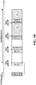
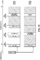
- FIGs. 2A and 2B are timing diagrams showing two examples of an unlicensed spectrum band access procedure by an ED to access an allocated time-frequency resource in an unlicensed spectrum band for grant-based uplink transmission in accordance with an embodiment of the present disclosure.
- a base station transmits in downlink (DL) subframe #n an uplink (UL) grant for the uplink subframe #n+k.
- the uplink subframe #n+k includes four start points #1-4.
- the ED performs an LBT operation at the boundary of subframe #n+k (which is also start point #1) and the start points #2 and #3. In this example, the LBT operation fails at the boundaries of subframe #n+k and start point #2 and passes at the start point #3.
- the ED In response to the LBT operation at the start point #3 succeeding, the ED begins transmitting an uplink transmission from start point #3.
- the uplink transmission includes an activation signal to indicate the start of the uplink transmission, and uplink payload data.
- the activation signal is transmitted within the unlicensed spectrum time-frequency resource allocated to the ED.
- the ED may transmit a reservation signal (not shown in FIGs. 2A and 2B ) within the allocated time-frequency resource between the end of the successful LBT and the transmission of the activation signal.
- the reservation signal is intended to prevent other devices from accessing the time-frequency resource the base station has allocated to the ED.
- a cyclic prefix (CP) extension of a following OFDM symbol is transmitted as the reservation signal. Transmitting the CP extension of the following OFDM symbol as the reservation signal may also mitigate inter symbol interference.
- CP cyclic prefix
- the ED is allocated a subset of subcarriers of a component carrier (CC) bandwidth.
- the second LBT operation is a narrowband LBT operation that is based on energy measured on the allocated subset of subcarriers during one or more OFDM symbol intervals immediately preceding a start point within the allocated time-frequency resource.
- the ED transmits the uplink transmission on the allocated subset of subcarriers within the remaining portion of the allocated time-frequency resource;
- the ED transmits the uplink transmission until the end of the allocated resource.
- the ED will adjust the transport block (TB) size used to transmit uplink traffic based on the amount of the allocated resource that remains after the successful LBT operation.
- the transmissions for different TB sizes corresponding to different start points can be prepared in advance in order to satisfy the short latency between the end of LBT and start of transmission. For example, if the LBT operation at the subframe boundary of subframe #n+k was successful, the ED may use a different TB size than if an LBT operation does not succeed until the start point #3.
- the base station performs a similar operation to configure an expected TB size to use in decoding the uplink payload data received from the ED.
- the ED may use rate matching or puncturing to fit the original TB into the accessible resource without changing the TB size.
- the ED may use packet segmentation to generate the uplink payload data to fit within the remaining portion of the allocated resource.
- the ED may transmit an updated buffer status report (BSR) as part of the uplink transmission to advise the base station of its updated buffer status due to the packet segmentation.
- BSR buffer status report
- the base station can determine the start point of uplink transmission from one or multiple pre-configured locations. If the uplink transmission starts from start points #1 or #2, the base station will detect an activation signal at the location of activation #1. Different sequences on the signals indicate whether the transmission began at start point #1 or #2. The start point #3 and #4 are indicated at the location of activation #2. The sequences are used to further distinguish start points #3 and #4.
- LBT operations are shown as being within the OFDM symbol intervals that immediately precede the subframe boundary and start points. More generally, as discussed in further detail below with reference to FIGs. 3A-3B , LBT operations can occupy one or more OFDM symbol intervals immediately before subframe/slot/mini-slot boundaries or one or more symbol intervals within the corresponding subframe/slot/mini-slot.
- an ED may be allocated an UL resource based on an interlace of physical resource blocks (PRBs) distributed within a channel bandwidth.
- PRBs physical resource blocks
- an activation signal may be transmitted on each of the plurality of PRBs of the interlace allocated to the ED.
- Regulations relating to unlicensed spectrum access may require that transmissions made within a given channel bandwidth satisfy a minimum occupancy channel bandwidth.
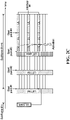
- FIG. 2C is a timing diagram showing an example of an unlicensed spectrum band access procedure by an ED to access a time-frequency resource in an unlicensed spectrum band for grant-based uplink transmission.
- the time-frequency resource allocated to the ED includes an interlace, Interlace #1, of PRBs.
- an activation signal is transmitted by the ED only on the PRBs of the allocated interlace.
- FIGs. 3A and 3B are timing diagrams showing two examples of the timing of LBT operations relative to start point in accordance with an embodiment of the present disclosure.
- the start point is at the OFDM symbol boundary.
- the LBT operation occupies time intervals immediately before the start point.
- an ED may keep the rest of symbol duration blank between the end of a successful LBT operation and the beginning of uplink transmission.
- the start point is located at a point after the OFDM symbol boundary such that it is located between OFDM symbol boundaries.
- the LBT operation occupies an LBT time interval immediately before the start point.
- the activation signal or DMRS starts at the first OFDM symbol boundary after the LBT operation passes at the start point.
- the ED may transmit a reservation signal for the remainder of OFDM symbol (OS) OS#1 before starting uplink transmission in the second OS interval (OS#2) of the mini-slot.
- the reservation signal may be a CP extension of the next OFDM symbol.
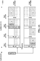
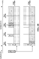
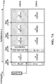
- FIGs. 4A and 4B are timing diagrams showing examples of an unlicensed spectrum band access procedure by an ED for grant-based uplink transmission that supports frequency domain multiplexing in accordance with an embodiment of the present disclosure.
- frequency domain multiplexing of uplink transmissions from different EDs is supported by performing wideband LBT operations at the subframe boundary and at potential start points within the subframe.
- two EDs (ED#1 and ED#2) are allocated non-overlapping physical resource blocks (PRB#1 and PRB#2), virtual resource blocks or interlaces.
- Each of the PRBs includes a respective subset of the subcarriers of a component carrier (CC) bandwidth, e.g. a respective subset of the subcarriers within a 20 MHz CC bandwidth.
- An interlace includes multiple resource blocks distributed within the component carrier (CC) or bandwidth part (BWP).
- the bandwidth of CC or BWP can be larger than a unit bandwidth defined in the channelization, e.g. 20MHz.
- the wideband LBT operations at the subframe boundary and potential start points within the subframe are based on energy measured on all of the subcarriers of the CC bandwidth during the time period conforming to regulation.
- the wideband LBT operations may measure the energy of CC/system bandwidth according to the Category 2 (CAT2 - LBT without random back-off) or Category 4 (CAT 4 - LBT with random back-off with variable size of contention window or extended CCA) LBT procedures defined for LTE license assisted access.
- the ED transmits its uplink transmission with blanking intervals immediately before each of the subsequent start points in order to avoid having its uplink transmission act as interference to the potential LBT operations of other EDs that may be scheduled in the same time-frequency resource.
- the uplink transmission transmitted by ED#2 after its successful LBT operation at the boundary of subframe #n+k includes blanking intervals immediately before the start points #2,#3 and #4.
- frequency domain multiplexing of uplink transmissions from different EDs is supported by performing a wideband LBT operation at a slot/subframe boundary and narrow band LBT operations at the start points within the duration of a slot or subframe. Similar to the example shown in FIG. 4A , in the example shown in FIG. 4B two EDs (ED#1 and ED#2) are allocated non-overlapping physical resource blocks (PRB#1 and PRB#2) that each include a respective subset of the subcarriers of a CC bandwidth. However, unlike the example shown in FIG. 4A , in the example shown in FIG.
- the LBT operations that are performed immediately before the start points # 2, 3 and 4 within subframe #n+k are narrowband LBT operations that are based on energy measured only on the respective subset of subcarriers allocated to the ED.
- the duration of a narrow band LBT operation is equal to and aligned with one OFDM symbol interval.
- two EDs (ED#1 and ED#2) are allocated non-overlapping interlaces (Interlace#1 and Interlace#2) that each include a plurality of PRBs distributed within a CC or BWP.
- the LBT operations that are performed immediately before the start points # 2, 3 and 4 within subframe #n+k are narrowband LBT operations that are based on energy measured only on the respective PRBs of the interlace allocated to the ED.
- the wideband and narrowband LBT operations occur before the start points in the slot/subframe.
- the start point may start at the OFDM symbol boundary or in the middle of OFDM symbol duration.
- the term "wideband LBT” is used herein to refer to an LBT procedure in which an ED performs LBT on the channel bandwidth of a component carrier or bandwidth part in which the UL resource is scheduled
- the term “narrowband LBT” is used herein to refer to an LBT procedure in which the bandwidth of the LBT performed by the ED is narrower than the full channel bandwidth of a component carrier or bandwidth part in which the UL resource is scheduled, e.g., a bandwidth equal to the frequency resource allocated to the ED.
- FIGs. 5A , 5B and 5C are timing diagrams showing examples of an unlicensed spectrum band access procedure by an ED for grant-based uplink transmission that supports UL MU MIMO in accordance with an embodiment of the present disclosure.
- two EDs (ED#1 and ED#2) are allocated the same time-frequency resource, and their respective uplink transmissions are distinguished by spatial layer separation.
- UL MU MIMO is supported by reserving the first symbol(s) of each start point for DMRS and/or activation signal transmission for all EDs scheduled in the same time-frequency resource.
- the uplink transmission transmitted by ED#2 after its successful LBT operation at the boundary of subframe #n+k includes ED#2's DMRS and/or activation signal at the location of start points #1-4, which the base station can potentially use to estimate the channel and decode uplink data in each mini-slot. This means that the base station can potentially start decoding ED#2's uplink payload data in each mini-slot as soon as it is received.
- UL MU MIMO is supported by reserving the pre-configured symbol interval(s) after the last start point in the subframe, e.g., the last OS interval(s) of the subframe, for DMRS transmission.
- each UE transmits an activation signal at the beginning of its uplink transmission and then transmits its DMRS in the last OS intervals at the end of the subframe #n+k.
- UE#2 transmits its activation signal in start point #1 after its successful LBT operation at the boundary of subframe #n+k, but does not transmit its DMRS until the last OS intervals at the end of subframe #n+k.
- UE#1 transmits its activation signal at start point #3 after its LBT operation succeeds, but does not transmit its DMRS until the last OS intervals at the end of subframe #n+k.
- This example saves signaling overhead relative to the example shown in FIG. 5A (because the first symbol(s) of each mini-slot are not reserved for DMRS and/or activation signal transmission), at the cost of potentially higher latency, because the base station has to wait until it receives the DMRS at the end of the subframe before it can decode the channel and the uplink data.
- the activation signal can be a "lite" version that may be suitable for activation detection, but not for channel estimation.
- an activation signal may be sparse in the frequency domain, which is shown by way of example in the activation signal transmitted by UE#1 at start point #3 in FIG. 5B .
- the positions of the activation signal and DMRS are pre-configured.
- the possible positions are at the start point of #2 and #4.
- ED#2 starts uplink transmission from start point #1 and will transmit DMRS at both locations, with the DMRS sequence at least in first location indicating the uplink transmission starting at start point #1.
- ED#1 starts uplink transmission from start point #3 and will transmit DMRS at the second location with a DMRS sequence indicating the start point #3.
- all DMRS sequences are orthogonal or have low cross correlation, which facilitates reliable channel estimation across different spatial layers.
- the use of multiple DMRSs can potentially provide better channel estimation in scenarios of higher mobility.
- the receiving latency is smaller than the case in FIG.5B .
- a larger buffer size is required because the base station does not know exactly when the uplink transmission starts until the DMRS symbol is detected.
- the time-frequency resource scheduled to an ED may be across one LBT bandwidth in the frequency domain, e.g. multiple PRBs across 20 MHz channel boundaries.
- FIG. 6 is a timing diagram showing an example of an unlicensed spectrum band access procedure by an ED for grant-based uplink transmission that supports the scheduling of an ED on such a time-frequency resource.
- an ED is allocated a time-frequency resource that includes a set of subcarriers of a first 20 MHz CC bandwidth and a set of subcarriers of a second 20 MHz CC bandwidth.
- the ED performs LBT operations for the first 20 MHz CC bandwidth that are based on energy measured on the allocated set of subcarriers of the first 20 MHz CC bandwidth and LBT operations for the second 20 MHz CC bandwidth that are based on energy measured on the allocated set of subcarriers of the second 20 MHz CC bandwidth.
- the LBT operations are performed at the potential start points in a slot/subframe.
- both of the initial LBT operations for the first and second 20 MHz CC bandwidths at the subframe boundary of subframe #n+k fail.
- the LBT operation for the second 20 MHz CC bandwidth at the start point #2 also fails.
- the LBT operation for the first 20 MHz CC bandwidth at the start point #2 succeeds, and the ED begins transmitting an uplink transmission on an allocated set of subcarriers of the first 20 MHz CC bandwidth at start point #2 and continues to do so until the end of the slot/subframe.
- the ED does not continue with further LBT operations for the second 20 MHz CC bandwidth at the boundaries of start point #3 or #4 once the LBT operation for the first 20 MHz CC bandwidth at the start point #2 succeeds.
- the ED may continue to perform LBT operations for the second 20 MHz CC bandwidth at subsequent start points within the allocated time-frequency resource even after an LBT operation for the first 20 MHz CC bandwidth succeeds. Furthermore, if a subsequent LBT operation for the second 20 MHz CC bandwidth succeeds, the ED may begin transmitting an uplink transmission on the allocated subset of the second 20 MHz CC bandwidth within the portion of the allocated time-frequency resource that remains after the success of the LBT operation for the second 20 MHz CC bandwidth.
- a code block (CB) size may be adapted based on the time-frequency resource size, in terms of frequency bandwidth and/or time within the allocated time-frequency resource, that is available for uplink transmission. For example, referring again to FIG. 6 , the CB size may be adapted to account for only half of the frequency bandwidth of the allocated time-frequency resource (i.e., only one of the two 20 MHz CC bandwidths) and only one interval between two consecutive start points (e.g. number of OFDM symbols between start point #n and start point #n+1).
- FIGs. 7A and 7B are timing diagrams showing two options for adapting the CBs that may be transmitted as part of the uplink transmission in the scenario depicted in FIG. 6 .
- code blocks CB(G) 11, CB(G) 12, CB(G) 13 and CB(G) 14 are mapped to start point #1, start point #2, start point #3 and start point #4, respectively, on the allocated set of subcarriers of the first 20 MHz CC bandwidth.
- code blocks CB(G) 21, CB(G) 22, CB(G) 23 and CB(G) 24 are mapped to start point #1, start point #2, start point #3 and start point #4, respectively, on the allocated set of subcarriers of the second 20 MHz CC bandwidth.
- the uplink payload data that is transmitted as part of the uplink transmission that starts at start point #2 includes code blocks CB(G) 12, CB(G) 13 and CB(G) 14. These are the code blocks of data that are mapped to the start points within the remaining portion of the allocated time-frequency resource after the LBT operation succeeds at start point #2.
- the uplink payload data this is transmitted as part of the uplink transmission includes CB(G) 11, CB(G) 12 and CB(G) 13. These are the code blocks of data starting with the code block mapped to the first start point of the allocated time-frequency resource and continuing sequentially in the time domain.
- the un-transmitted CB may be rescheduled or retransmitted automatically.
- FIG. 8A is a flow diagram of example operations 800 in an ED according to an embodiment of the present disclosure.
- the ED transmits an uplink scheduling request to a base station.
- the ED receives an uplink grant message from the base station indicating that the ED has been allocated a time-frequency resource for uplink transmission in an unlicensed spectrum.
- the ED performs a first LBT operation at a first start time based on a start point configuration for the allocated time-frequency resource as discussed previously.
- the ED proceeds to 816 (the Y path from 808), in which the ED transmits an uplink transmission within a remaining portion of the allocated time-frequency resource.
- the uplink transmission includes an activation signal and uplink payload data as discussed previously.
- the ED proceeds to 810 (the N path from 808), in which the ED performs a second LBT operation at a later start time based on the start point configuration within the allocated time-frequency resource.
- the ED proceeds to 816 (the Y path from 812) and transmits an uplink transmission within the remaining portion of the allocated time-frequency resource.
- the ED proceeds to 814 (the N path from 812), in which the ED checks if the time-frequency resource has ended. This may involve, for example, checking if the start point configuration indicates that there is still at least one possible start point for uplink transmission remaining in the allocated time-frequency resource.
- the ED may return to 802 (the Y path from 814) to transmit another uplink scheduling request. If there is still at least one possible start point left for uplink transmission, the ED may return to 810 to perform another LBT operation at a later start time based on the start point configuration. In this way, if the first LBT operation at 808 fails, the ED may continue to loop through steps 810, 812 and 814 until either the time-frequency resource has ended or one of the LBT operations at 812 is successful and the ED is able to transmit an uplink transmission at 816.
- example operations 800 could include performing the illustrated operations in any of various ways and/or performing additional or fewer operations.
- variations of the example operations 800 could include any or all of the following:
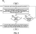
- Fig. 9 is a flow diagram of example operations 900 in a base station.
- the base station receives an uplink scheduling request from a first ED.
- the base station transmits a first uplink grant message for the first ED, the first uplink grant message indicating a time-frequency resource allocated to the first ED for uplink transmission in an unlicensed spectrum band.
- the base station monitors for detection of an activation signal associated with the first ED at start times based on a start point configuration within the allocated time-frequency resource. If an activation signal associated with the first ED is detected at 906, the base station proceeds to 910 (the Y path from 906), in which the base station decodes uplink payload data for the first ED that was received between the start of uplink transmission from the first ED and the end of the allocated time-frequency resource.
- the base station proceeds to 908, in which the base station checks if the time-frequency resource has ended, e.g., if the start point configuration indicates that no further start points for uplink transmission remain in the allocated time-frequency resource. If the time-frequency resource has ended, the base station may return to the start and await a further uplink scheduling request from the first ED (the Y path from 908). If the time-frequency resource has not yet ended, such that at least one possible start point for uplink transmission remains within the allocated time-frequency resource, then the base station may return to 906 (the N path from 908) to continue to monitor for detection of an activation signal associated with the first ED. In this way, the base station may continue to monitor for the activation signal until either the activation signal associated with the first ED is detected or the allocated time-frequency resource ends.
- the base station may return to 906 (the N path from 908) to continue to monitor for detection of an activation signal associated with the first ED. In this way, the base station may continue to monitor for the activation signal until either the activ
- example operations 900 could include performing the illustrated operations in any of various ways and/or performing additional or fewer operations.
- variations of the example operations 900 could include any or all of the following:
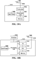
- FIGs. 10A and 10B illustrate example devices that may implement the methods and teachings according to this disclosure.
- FIG. 10A illustrates an example ED 110
- FIG. 10B illustrates an example base station 170. These components could be used in the communication system 100 or in any other suitable system.
- the ED 110 includes at least one processing unit 1400.
- the processing unit 1400 implements various processing operations of the ED 110.
- the processing unit 1400 could perform signal coding, data processing, power control, input/output processing, or any other functionality enabling the ED 110 to operate in the communication system 100.
- the processing unit 1400 may also be configured to implement some or all of the functionality and/or embodiments described in more detail above.
- Each processing unit 1400 includes any suitable processing or computing device configured to perform one or more operations.
- Each processing unit 1400 could, for example, include a microprocessor, microcontroller, digital signal processor, field programmable gate array, or application specific integrated circuit.
- the ED 110 also includes at least one transceiver 1402.
- the transceiver 1402 is configured to modulate data or other content for transmission by at least one antenna or Network Interface Controller (NIC) 1404.
- the transceiver 1402 is also configured to demodulate data or other content received by the at least one antenna 1404.
- Each transceiver 1402 includes any suitable structure for generating signals for wireless or wired transmission and/or processing signals received wirelessly or by wire.
- Each antenna 1404 includes any suitable structure for transmitting and/or receiving wireless or wired signals.
- One or multiple transceivers 1402 could be used in the ED 110.
- One or multiple antennas 1404 could be used in the ED 110.
- a transceiver 1402 could also be implemented using at least one transmitter and at least one separate receiver.
- the ED 110 further includes one or more input/output devices 1406 or interfaces (such as a wired interface to the internet 150).
- the input/output devices 1406 permit interaction with a user or other devices in the network.
- Each input/output device 1406 includes any suitable structure for providing information to or receiving information from a user, such as a speaker, microphone, keypad, keyboard, display, or touch screen, including network interface communications.
- the ED 110 includes at least one memory 1408.
- the memory 1408 stores instructions and data used, generated, or collected by the ED 110.
- the memory 1408 could store software instructions or modules configured to implement some or all of the functionality and/or embodiments described above and that are executed by the processing unit(s) 1400.
- Each memory 1408 includes any suitable volatile and/or non-volatile storage and retrieval device(s). Any suitable type of memory may be used, such as random access memory (RAM), read only memory (ROM), hard disk, optical disc, subscriber identity module (SIM) card, memory stick, secure digital (SD) memory card, and the like.
- RAM random access memory
- ROM read only memory
- SIM subscriber identity module
- SD secure digital
- the base station 170 includes at least one processing unit 1450, at least one transmitter 1452, at least one receiver 1454, one or more antennas 1456, at least one memory 1458, and one or more input/output devices or interfaces 1466.
- a transceiver not shown, may be used instead of the transmitter 1452 and receiver 1454.
- a scheduler 253 may be coupled to the processing unit 1450. The scheduler 253 may be included within or operated separately from the base station 170.
- the processing unit 1450 implements various processing operations of the base station 170, such as signal coding, data processing, power control, input/output processing, or any other functionality.
- the processing unit 1450 can also be configured to implement some or all of the functionality and/or embodiments described in more detail above.
- Each processing unit 1450 includes any suitable processing or computing device configured to perform one or more operations.
- Each processing unit 1450 could, for example, include a microprocessor, microcontroller, digital signal processor, field programmable gate array, or application specific integrated circuit.
- Each transmitter 1452 includes any suitable structure for generating signals for wireless or wired transmission to one or more EDs or other devices.
- Each receiver 1454 includes any suitable structure for processing signals received wirelessly or by wire from one or more EDs or other devices. Although shown as separate components, at least one transmitter 1452 and at least one receiver 1454 could be combined into a transceiver.
- Each antenna 1456 includes any suitable structure for transmitting and/or receiving wireless or wired signals. Although a common antenna 1456 is shown here as being coupled to both the transmitter 1452 and the receiver 1454, one or more antennas 1456 could be coupled to the transmitter(s) 1452, and one or more separate antennas 1456 could be coupled to the receiver(s) 1454.
- Each memory 1458 includes any suitable volatile and/or non-volatile storage and retrieval device(s) such as those described above in connection to the ED 110.
- the memory 1458 stores instructions and data used, generated, or collected by the base station 170.
- the memory 1458 could store software instructions or modules configured to implement some or all of the functionality and/or embodiments described above and that are executed by the processing unit(s) 1450.
- Each input/output device 1466 permits interaction with a user or other devices in the network.
- Each input/output device 1466 includes any suitable structure for providing information to or receiving/providing information from a user, including network interface communications.
- a signal may be transmitted by a transmitting unit or a transmitting module.
- a signal may be received by a receiving unit or a receiving module.
- a signal may be processed by a processing unit or a processing module.
- the respective units/modules may be hardware, software, or a combination thereof.
- one or more of the units/modules may be an integrated circuit, such as field programmable gate arrays (FPGAs) or application-specific integrated circuits (ASICs).
- FPGAs field programmable gate arrays
- ASICs application-specific integrated circuits
- Embodiments of the disclosure can be represented as a computer program product stored in a machine-readable medium (also referred to as a computer-readable medium, a processor-readable medium, or a computer usable medium having a computer-readable program code embodied therein).
- the machine-readable medium can be any suitable tangible, non-transitory medium, including magnetic, optical, or electrical storage medium including a diskette, compact disk read only memory (CD-ROM), memory device (volatile or non-volatile), or similar storage mechanism.
- the machine-readable medium can contain various sets of instructions, code sequences, configuration information, or other data, which, when executed, cause a processor to perform steps in a method according to an embodiment of the disclosure.
- FIG. 1 is a block diagram of a communication system in which embodiments may be implemented. Other embodiments could be implemented in communication systems that include more network elements than shown, or that have different topologies than the example shown. Similarly, the examples in the other figures are also intended solely for illustrative purposes.
Landscapes
- Engineering & Computer Science (AREA)
- Computer Networks & Wireless Communication (AREA)
- Signal Processing (AREA)
- Mobile Radio Communication Systems (AREA)
Claims (14)
- Verfahren für eine Elektronische Vorrichtung (Electronic Device - ED) in einem drahtlosen Netzwerk, wobei das Verfahren Folgendes umfasst:Empfangen (804), durch die ED, einer Uplink-Grant-Nachricht von einer Basisstation, wobei die Uplink-Grant-Nachricht eine Zeit-Frequenz-Ressource angibt, die der ED für eine Uplink-Übertragung in einem nicht lizenzierten Spektrumband zugewiesen wird;Durchführen (806), durch die ED, eines ersten Listen-Before-Talk(LBT)-Vorgangs für die zugewiesene Zeit-Frequenz-Ressource;falls der erste LBT-Vorgang fehlschlägt, Durchführen (810), durch die ED; eines zweiten LBT-Vorgangs innerhalb der zugewiesenen Zeit-Frequenz-Ressource, dadurch gekennzeichnet, dassals Reaktion auf den LBT-Vorgang, der erfolgreich ist (812), Übertragen (816), durch die ED, einer Uplink-Übertragung innerhalb eines verbleibenden Abschnitts der zugewiesenen Zeit-Frequenz-Ressource, wobei die Uplink-Übertragung Folgendes umfasst:ein Aktivierungssignal, um einen Start der Uplink-Übertragung anzugeben; undUplink-Nutzlastdaten,wobei der ED eine Untermenge von Unterträgern einer Komponententräger(component carrier- CC)-Bandbreite zugewiesen wird;der zweite LBT-Vorgang ein Schmalband-LBT-Vorgang ist, der auf Energie basiert, die auf der zugewiesenen Untermenge von Unterträgern während eines oder mehrerer Orthogonalfrequenzmultiplex(orthogonal frequency division multiplexing - OFDM)-Symbolintervalle gemessen wird, die einem Startpunkt innerhalb der zugewiesenen Zeit-Frequenz-Ressource unmittelbar vorausgehen, wobei eine Bandbreite des Schmalband-LBT-Vorgangs, der durch die ED durchgeführt wird, schmaler als eine volle Kanalbandbreite des CC oder des Bandbreitenteils ist, in dem eine Uplink-Ressource geplant ist; unddas Übertragen (816) der Uplink-Übertragung das Übertragen, durch die ED, der Uplink-Übertragung auf der zugewiesenen Untergruppe von Unterträgern innerhalb des verbleibenden Abschnitts der zugewiesenen Zeit-Frequenz-Ressource umfasst.
- Verfahren nach Anspruch 1, wobei der zweite LBT-Vorgang zu einer Startzeit basierend auf einer Startpunktkonfiguration innerhalb der zugewiesenen Zeit-Frequenz-Ressource durchgeführt wird.
- Verfahren nach Anspruch 2, wobei die Startpunktkonfiguration die Konfiguration mehrerer möglicher Startpunkte der Uplink-Übertragung innerhalb eines Unterrahmens angibt.
- Verfahren nach Anspruch 3, wobei sich jeder Startpunkt entweder an einer OFDM-Symbolgrenze oder in der Mitte zwischen angrenzenden OFDM-Symbolgrenzen innerhalb der zugewiesenen Zeit-Frequenz-Ressource befindet.
- Verfahren nach einem der Ansprüche 2 bis 4, das ferner das Empfangen, durch die ED von der Basisstation, von Informationen umfasst, die die Startpunktkonfiguration angeben.
- Verfahren nach einem der Ansprüche 1 bis 5, wobei das Aktivierungssignal ein Demodulationsreferenzsignal (demodulation reference signal - DMRS) ist.
- Verfahren nach einem der Ansprüche 2 bis 6, wobei das Übertragen der Uplink-Übertragung innerhalb des verbleibenden Abschnitts der zugewiesenen Zeit-Frequenz-Ressource das Übertragen, durch die ED, der Uplink-Übertragung mit einem oder mehreren Austastlücken innerhalb des verbleibenden Abschnitts der zugewiesenen Zeit-Frequenz-Ressource basierend auf der Startpunktkonfiguration umfasst.
- Verfahren nach einem der Ansprüche 2 bis 7, wobei das Durchführen des zweiten LBT-Vorgangs innerhalb der zugewiesenen Zeit-Frequenz-Ressource das Durchführen, durch die ED, eines LBT-Vorgangs zu jeder von mehreren Startzeiten basierend auf der Startpunktkonfiguration umfasst, bis einer der LBT-Vorgänge erfolgreich ist.
- Verfahren nach einem der Ansprüche 1 bis 8, wobei der zweite LBT-Vorgang durchgeführt wird, während ein oder mehrere OFDM-Symbolintervalle einen Startpunkt innerhalb der zugewiesenen Zeit-Frequenz-Ressource unmittelbar vorausgehen.
- Verfahren nach Anspruch 9, das ferner, als Reaktion auf den LBT-Vorgang, der erfolgreich ist, das Übertragen, durch die ED, eines Reservierungssignals zwischen dem Startpunkt der Uplink-Übertragung und der nächsten OFDM-Symbolgrenze nach dem Startpunkt umfasst.
- Verfahren nach Anspruch 10, wobei das Reservierungssignal eine zyklische Präfixerweiterung des folgenden OFDM-Symbols beinhaltet.
- Verfahren nach einem der Ansprüche 1 bis 11, wobei das Übertragen der Uplink-Übertragung innerhalb des verbleibenden Abschnitts der zugewiesenen Zeit-Frequenz-Ressource das Übertragen, durch die ED, des Aktivierungssignals an einem Startpunkt umfasst, der Teil einer vorkonfigurierten Untergruppe möglicher Startpunkte innerhalb der zugewiesenen Zeit-Frequenz-Ressource ist.
- Verfahren nach Anspruch 12, wobei das Aktivierungssignal durch die ED aus mehreren Aktivierungssignalen ausgewählt wird, die der ED zugewiesen sind, wobei die mehreren Aktivierungssignale Folgendes umfassen:ein erstes Aktivierungssignal, um anzugeben, dass die Uplink-Übertragung an einem Startpunkt startet, der dem Startpunkt vorausgeht, an dem das erste Aktivierungssignal übertragen wird; undein zweites Aktivierungssignal, um anzugeben, dass die Uplink-Übertragung an oder nach dem Startpunkt startet, an dem das erste Aktivierungssignal übertragen wird.
- Elektronische Vorrichtung (110) (ED) die Folgendes umfasst:einen oder mehrere Prozessoren (1400); undein nicht flüchtiges computerlesbares Speichermedium (1408), das ein Programm für eine Ausführung durch den einen oder die mehreren Prozessoren (1400) speichert, wobei das Programm Anweisungen beinhaltet, um das Verfahren nach einem der Ansprüche 1 bis 13 durchzuführen.
Applications Claiming Priority (3)
| Application Number | Priority Date | Filing Date | Title |
|---|---|---|---|
| US201762512551P | 2017-05-30 | 2017-05-30 | |
| US15/989,902 US10687313B2 (en) | 2017-05-30 | 2018-05-25 | Grant-based uplink transmission in unlicensed band |
| PCT/CN2018/088542 WO2018219235A1 (en) | 2017-05-30 | 2018-05-26 | Grant-based uplink transmission in unlicensed band |
Publications (3)
| Publication Number | Publication Date |
|---|---|
| EP3626008A1 EP3626008A1 (de) | 2020-03-25 |
| EP3626008A4 EP3626008A4 (de) | 2020-05-20 |
| EP3626008B1 true EP3626008B1 (de) | 2022-10-05 |
Family
ID=64456355
Family Applications (1)
| Application Number | Title | Priority Date | Filing Date |
|---|---|---|---|
| EP18809565.7A Active EP3626008B1 (de) | 2017-05-30 | 2018-05-26 | Auf berechtigung basierende uplink-übertragung in einem unlizenzierten band |
Country Status (4)
| Country | Link |
|---|---|
| US (1) | US10687313B2 (de) |
| EP (1) | EP3626008B1 (de) |
| CN (1) | CN110651524B (de) |
| WO (1) | WO2018219235A1 (de) |
Cited By (1)
| Publication number | Priority date | Publication date | Assignee | Title |
|---|---|---|---|---|
| EP3759990B1 (de) * | 2018-03-01 | 2024-02-14 | QUALCOMM Incorporated | Mehrere startsymbole für neufunk-unlizenzierten (nr-u) gemeinsam genutzten physischen uplink-kanal (pusch) |
Families Citing this family (29)
| Publication number | Priority date | Publication date | Assignee | Title |
|---|---|---|---|---|
| CN108293265B (zh) * | 2015-10-21 | 2021-07-27 | 松下电器(美国)知识产权公司 | 用户设备以及无线通信方法 |
| US11324047B2 (en) * | 2017-11-10 | 2022-05-03 | Qualcomm Incorporated | NR-unlicensed transmission opportunity structure with flexible starting point |
| US10750492B2 (en) * | 2017-12-20 | 2020-08-18 | Qualcomm Incorporated | Resource assignment in NR-SS |
| US11363630B2 (en) * | 2018-03-01 | 2022-06-14 | Qualcomm Incorporated | Bandwidth part (BWP) configuration for subband access in new radio-unlicensed (NR-U) |
| GB2575816A (en) * | 2018-07-23 | 2020-01-29 | Tcl Communication Ltd | Transmission techniques in a cellular network |
| US11272540B2 (en) | 2018-08-09 | 2022-03-08 | Ofinno, Llc | Channel access and uplink switching |
| US11272539B2 (en) | 2018-08-09 | 2022-03-08 | Ofinno, Llc | Channel access and bandwidth part switching |
| EP3878224A4 (de) * | 2018-11-08 | 2022-06-29 | Lenovo (Beijing) Limited | Verfahren und vorrichtung zum steuerungskanaldesign zur datenübertragung auf unlizenziertem spektrum |
| CN109688626B (zh) * | 2018-12-10 | 2021-10-22 | 中国科学院上海微系统与信息技术研究所 | 一种基于帧的设备的先听后说参数配置方法 |
| CN109462895B (zh) * | 2018-12-14 | 2022-03-25 | 京信网络系统股份有限公司 | 用户设备上行调度方法和装置 |
| JP7270649B2 (ja) * | 2019-01-10 | 2023-05-10 | 京セラ株式会社 | 通信制御方法 |
| BR112021014409A2 (pt) * | 2019-01-23 | 2021-09-21 | Ntt Docomo, Inc. | Aparelho de transmissão e método de radiocomunicação |
| CN111294868B (zh) * | 2019-01-31 | 2022-09-30 | 展讯通信(上海)有限公司 | 先听后说操作的执行方法及装置、存储介质、终端、基站 |
| EP4646008A3 (de) | 2019-03-27 | 2026-02-18 | InterDigital Patent Holdings, Inc. | Verfahren für unlizenzierten breitbandkanalzugang |
| EP3949653B1 (de) * | 2019-03-29 | 2022-07-20 | Telefonaktiebolaget LM Ericsson (publ) | Verbesserte antennensysteme für räumliches listen-before-talk |
| CN113557784B (zh) * | 2019-03-29 | 2024-04-12 | 富士通株式会社 | 上行传输方法、上行调度方法、装置和通信系统 |
| PH12022550970A1 (en) * | 2019-11-08 | 2023-09-25 | Qualcomm Inc | Configured grant channel occupancy time sharing procedure |
| CN114930966A (zh) | 2020-01-10 | 2022-08-19 | 鸿颖创新有限公司 | 用于处理nr-u中的上行链路的(重新)传输的方法和装置 |
| CN120857273A (zh) * | 2020-02-13 | 2025-10-28 | 高通股份有限公司 | 将上行链路动态准予与所配置上行链路传输交叠 |
| WO2021179221A1 (zh) * | 2020-03-11 | 2021-09-16 | Oppo广东移动通信有限公司 | 数据传输方法、装置、设备及存储介质 |
| US12432775B2 (en) | 2020-03-17 | 2025-09-30 | Beijing Xiaomi Mobile Software Co., Ltd. | Communication method, apparatus, and device, and readable storage medium |
| CN113498202A (zh) * | 2020-04-07 | 2021-10-12 | 维沃移动通信有限公司 | 一种非授权频段传输的方法及通信设备 |
| WO2021206400A1 (ko) * | 2020-04-08 | 2021-10-14 | 엘지전자 주식회사 | 채널 접속 절차를 수행하는 방법 및 이를 위한 장치 |
| EP3944547A1 (de) * | 2020-07-24 | 2022-01-26 | Nokia Technologies Oy | Bestimmung der erweiterung des zyklischen präfix (cp) und des listen-before-talk (lbt)-typs für uplink-übertragungen |
| WO2022026161A1 (en) * | 2020-07-30 | 2022-02-03 | Intel Corporation | Reservation signal for communications above 52.6 ghz |
| CN114449539B (zh) * | 2020-11-02 | 2023-12-01 | 华为技术有限公司 | 波束训练方法、装置及存储介质 |
| CN115190643A (zh) * | 2021-04-02 | 2022-10-14 | 大唐移动通信设备有限公司 | 一种上行重复传输方法、装置、设备及存储介质 |
| CN112954674B (zh) * | 2021-04-13 | 2022-03-22 | 广州奥融科技有限公司 | 一种远程数据安全加密方法及系统 |
| EP4613028A4 (de) * | 2022-11-02 | 2025-12-31 | Nec Corp | Verfahren, vorrichtung und computerlesbares medium für sidelink-kommunikationen |
Family Cites Families (10)
| Publication number | Priority date | Publication date | Assignee | Title |
|---|---|---|---|---|
| EP2966789B1 (de) * | 2013-03-07 | 2019-02-13 | LG Electronics Inc. | Verfahren und vorrichtung zum empfangen von signalen von einer station in einem wlan-system |
| JP2017521191A (ja) * | 2014-07-25 | 2017-08-03 | ノボ・ノルデイスク・エー/エス | 医療装置用のナットアセンブリ |
| EP3873164B1 (de) | 2014-11-17 | 2025-04-16 | Apple Inc. | Entwurf von listen-before-talk (lbt) für betrieb mit uplink-lizenziertem unterstütztem zugriff (laa) in einem unlizenzierten band |
| CN104333873A (zh) * | 2014-11-28 | 2015-02-04 | 东莞宇龙通信科技有限公司 | 信道检测方法及系统、具有基站功能的设备和终端 |
| CN107211441B (zh) | 2015-01-30 | 2021-07-30 | 苹果公司 | 用于许可-辅助的接入的上行调度 |
| JP6298904B2 (ja) | 2015-01-30 | 2018-03-20 | 京セラ株式会社 | ユーザ端末、方法、及び移動通信システム |
| JP6637163B2 (ja) * | 2015-09-17 | 2020-01-29 | エルジー エレクトロニクス インコーポレイティド | 非免許帯域を支援する無線接続システムにおいてマルチキャリア上でlbt過程を行う方法及び装置 |
| CN108029023B (zh) | 2015-09-25 | 2021-11-30 | 松下电器(美国)知识产权公司 | 用户设备和无线通信方法 |
| KR102307242B1 (ko) * | 2016-05-20 | 2021-09-30 | 텔레호낙티에볼라게트 엘엠 에릭슨(피유비엘) | 비면허 스펙트럼에서의 다수의 서브프레임들의 스케줄링 |
| US11038650B2 (en) * | 2017-05-05 | 2021-06-15 | Qualcomm Incorporated | Configuration of downlink and uplink partial subframes in shared radio frequency spectrum |
-
2018
- 2018-05-25 US US15/989,902 patent/US10687313B2/en active Active
- 2018-05-26 CN CN201880033440.3A patent/CN110651524B/zh active Active
- 2018-05-26 WO PCT/CN2018/088542 patent/WO2018219235A1/en not_active Ceased
- 2018-05-26 EP EP18809565.7A patent/EP3626008B1/de active Active
Cited By (1)
| Publication number | Priority date | Publication date | Assignee | Title |
|---|---|---|---|---|
| EP3759990B1 (de) * | 2018-03-01 | 2024-02-14 | QUALCOMM Incorporated | Mehrere startsymbole für neufunk-unlizenzierten (nr-u) gemeinsam genutzten physischen uplink-kanal (pusch) |
Also Published As
| Publication number | Publication date |
|---|---|
| CN110651524B (zh) | 2022-02-18 |
| EP3626008A1 (de) | 2020-03-25 |
| EP3626008A4 (de) | 2020-05-20 |
| CN110651524A (zh) | 2020-01-03 |
| US20180352537A1 (en) | 2018-12-06 |
| US10687313B2 (en) | 2020-06-16 |
| WO2018219235A1 (en) | 2018-12-06 |
Similar Documents
| Publication | Publication Date | Title |
|---|---|---|
| EP3626008B1 (de) | Auf berechtigung basierende uplink-übertragung in einem unlizenzierten band | |
| US11570804B2 (en) | Resource allocation for transmission with configured grant in unlicensed spectrum | |
| US12004214B2 (en) | Channel access mechanism for random access channel in unlicensed spectrum | |
| JP7317152B2 (ja) | アンライセンススペクトルにおける構成グラントを伴う送信のための物理アップリンク共有チャネル拡張 | |
| US11632195B2 (en) | Method for transmission of HARQ feedback in group common downlink control information | |
| EP3718332B1 (de) | Semipersistente planung für downlink mit geteiltem spektrum | |
| US11323989B2 (en) | Method and apparatus for bandwidth indication in unlicensed spectrum | |
| EP3738381B1 (de) | Systeme und verfahren zur zuweisung von uplink-steuerkanalressourcen in nichtlizenziertem spektrum | |
| US11265849B2 (en) | Grant-based uplink transmission in unlicensed band | |
| RU2784460C2 (ru) | Выделение ресурсов для передачи со сконфигурированным грантом в нелицензируемом спектре | |
| RU2777374C2 (ru) | Адаптация передачи и доступ без предоставления |
Legal Events
| Date | Code | Title | Description |
|---|---|---|---|
| STAA | Information on the status of an ep patent application or granted ep patent |
Free format text: STATUS: THE INTERNATIONAL PUBLICATION HAS BEEN MADE |
|
| PUAI | Public reference made under article 153(3) epc to a published international application that has entered the european phase |
Free format text: ORIGINAL CODE: 0009012 |
|
| STAA | Information on the status of an ep patent application or granted ep patent |
Free format text: STATUS: REQUEST FOR EXAMINATION WAS MADE |
|
| 17P | Request for examination filed |
Effective date: 20191217 |
|
| AK | Designated contracting states |
Kind code of ref document: A1 Designated state(s): AL AT BE BG CH CY CZ DE DK EE ES FI FR GB GR HR HU IE IS IT LI LT LU LV MC MK MT NL NO PL PT RO RS SE SI SK SM TR |
|
| AX | Request for extension of the european patent |
Extension state: BA ME |
|
| A4 | Supplementary search report drawn up and despatched |
Effective date: 20200420 |
|
| RIC1 | Information provided on ipc code assigned before grant |
Ipc: H04W 72/12 20090101AFI20200414BHEP Ipc: H04W 74/08 20090101ALN20200414BHEP Ipc: H04W 72/14 20090101ALN20200414BHEP |
|
| DAV | Request for validation of the european patent (deleted) | ||
| DAX | Request for extension of the european patent (deleted) | ||
| STAA | Information on the status of an ep patent application or granted ep patent |
Free format text: STATUS: EXAMINATION IS IN PROGRESS |
|
| 17Q | First examination report despatched |
Effective date: 20210325 |
|
| REG | Reference to a national code |
Ref country code: DE Ref legal event code: R079 Ref document number: 602018041477 Country of ref document: DE Free format text: PREVIOUS MAIN CLASS: H04W0072040000 Ipc: H04W0072120000 |
|
| GRAP | Despatch of communication of intention to grant a patent |
Free format text: ORIGINAL CODE: EPIDOSNIGR1 |
|
| STAA | Information on the status of an ep patent application or granted ep patent |
Free format text: STATUS: GRANT OF PATENT IS INTENDED |
|
| RIC1 | Information provided on ipc code assigned before grant |
Ipc: H04W 74/08 20090101ALN20220323BHEP Ipc: H04W 72/14 20090101ALN20220323BHEP Ipc: H04W 72/12 20090101AFI20220323BHEP |
|
| INTG | Intention to grant announced |
Effective date: 20220414 |
|
| GRAS | Grant fee paid |
Free format text: ORIGINAL CODE: EPIDOSNIGR3 |
|
| GRAA | (expected) grant |
Free format text: ORIGINAL CODE: 0009210 |
|
| STAA | Information on the status of an ep patent application or granted ep patent |
Free format text: STATUS: THE PATENT HAS BEEN GRANTED |
|
| AK | Designated contracting states |
Kind code of ref document: B1 Designated state(s): AL AT BE BG CH CY CZ DE DK EE ES FI FR GB GR HR HU IE IS IT LI LT LU LV MC MK MT NL NO PL PT RO RS SE SI SK SM TR |
|
| REG | Reference to a national code |
Ref country code: GB Ref legal event code: FG4D |
|
| REG | Reference to a national code |
Ref country code: CH Ref legal event code: EP |
|
| REG | Reference to a national code |
Ref country code: AT Ref legal event code: REF Ref document number: 1523566 Country of ref document: AT Kind code of ref document: T Effective date: 20221015 |
|
| REG | Reference to a national code |
Ref country code: IE Ref legal event code: FG4D |
|
| REG | Reference to a national code |
Ref country code: DE Ref legal event code: R096 Ref document number: 602018041477 Country of ref document: DE |
|
| REG | Reference to a national code |
Ref country code: LT Ref legal event code: MG9D |
|
| REG | Reference to a national code |
Ref country code: NL Ref legal event code: MP Effective date: 20221005 |
|
| REG | Reference to a national code |
Ref country code: AT Ref legal event code: MK05 Ref document number: 1523566 Country of ref document: AT Kind code of ref document: T Effective date: 20221005 |
|
| PG25 | Lapsed in a contracting state [announced via postgrant information from national office to epo] |
Ref country code: NL Free format text: LAPSE BECAUSE OF FAILURE TO SUBMIT A TRANSLATION OF THE DESCRIPTION OR TO PAY THE FEE WITHIN THE PRESCRIBED TIME-LIMIT Effective date: 20221005 |
|
| PG25 | Lapsed in a contracting state [announced via postgrant information from national office to epo] |
Ref country code: SE Free format text: LAPSE BECAUSE OF FAILURE TO SUBMIT A TRANSLATION OF THE DESCRIPTION OR TO PAY THE FEE WITHIN THE PRESCRIBED TIME-LIMIT Effective date: 20221005 Ref country code: PT Free format text: LAPSE BECAUSE OF FAILURE TO SUBMIT A TRANSLATION OF THE DESCRIPTION OR TO PAY THE FEE WITHIN THE PRESCRIBED TIME-LIMIT Effective date: 20230206 Ref country code: NO Free format text: LAPSE BECAUSE OF FAILURE TO SUBMIT A TRANSLATION OF THE DESCRIPTION OR TO PAY THE FEE WITHIN THE PRESCRIBED TIME-LIMIT Effective date: 20230105 Ref country code: LT Free format text: LAPSE BECAUSE OF FAILURE TO SUBMIT A TRANSLATION OF THE DESCRIPTION OR TO PAY THE FEE WITHIN THE PRESCRIBED TIME-LIMIT Effective date: 20221005 Ref country code: FI Free format text: LAPSE BECAUSE OF FAILURE TO SUBMIT A TRANSLATION OF THE DESCRIPTION OR TO PAY THE FEE WITHIN THE PRESCRIBED TIME-LIMIT Effective date: 20221005 Ref country code: ES Free format text: LAPSE BECAUSE OF FAILURE TO SUBMIT A TRANSLATION OF THE DESCRIPTION OR TO PAY THE FEE WITHIN THE PRESCRIBED TIME-LIMIT Effective date: 20221005 Ref country code: AT Free format text: LAPSE BECAUSE OF FAILURE TO SUBMIT A TRANSLATION OF THE DESCRIPTION OR TO PAY THE FEE WITHIN THE PRESCRIBED TIME-LIMIT Effective date: 20221005 |
|
| PG25 | Lapsed in a contracting state [announced via postgrant information from national office to epo] |
Ref country code: RS Free format text: LAPSE BECAUSE OF FAILURE TO SUBMIT A TRANSLATION OF THE DESCRIPTION OR TO PAY THE FEE WITHIN THE PRESCRIBED TIME-LIMIT Effective date: 20221005 Ref country code: PL Free format text: LAPSE BECAUSE OF FAILURE TO SUBMIT A TRANSLATION OF THE DESCRIPTION OR TO PAY THE FEE WITHIN THE PRESCRIBED TIME-LIMIT Effective date: 20221005 Ref country code: LV Free format text: LAPSE BECAUSE OF FAILURE TO SUBMIT A TRANSLATION OF THE DESCRIPTION OR TO PAY THE FEE WITHIN THE PRESCRIBED TIME-LIMIT Effective date: 20221005 Ref country code: IS Free format text: LAPSE BECAUSE OF FAILURE TO SUBMIT A TRANSLATION OF THE DESCRIPTION OR TO PAY THE FEE WITHIN THE PRESCRIBED TIME-LIMIT Effective date: 20230205 Ref country code: HR Free format text: LAPSE BECAUSE OF FAILURE TO SUBMIT A TRANSLATION OF THE DESCRIPTION OR TO PAY THE FEE WITHIN THE PRESCRIBED TIME-LIMIT Effective date: 20221005 Ref country code: GR Free format text: LAPSE BECAUSE OF FAILURE TO SUBMIT A TRANSLATION OF THE DESCRIPTION OR TO PAY THE FEE WITHIN THE PRESCRIBED TIME-LIMIT Effective date: 20230106 |
|
| P01 | Opt-out of the competence of the unified patent court (upc) registered |
Effective date: 20230524 |
|
| REG | Reference to a national code |
Ref country code: DE Ref legal event code: R097 Ref document number: 602018041477 Country of ref document: DE |
|
| PG25 | Lapsed in a contracting state [announced via postgrant information from national office to epo] |
Ref country code: SM Free format text: LAPSE BECAUSE OF FAILURE TO SUBMIT A TRANSLATION OF THE DESCRIPTION OR TO PAY THE FEE WITHIN THE PRESCRIBED TIME-LIMIT Effective date: 20221005 Ref country code: RO Free format text: LAPSE BECAUSE OF FAILURE TO SUBMIT A TRANSLATION OF THE DESCRIPTION OR TO PAY THE FEE WITHIN THE PRESCRIBED TIME-LIMIT Effective date: 20221005 Ref country code: EE Free format text: LAPSE BECAUSE OF FAILURE TO SUBMIT A TRANSLATION OF THE DESCRIPTION OR TO PAY THE FEE WITHIN THE PRESCRIBED TIME-LIMIT Effective date: 20221005 Ref country code: DK Free format text: LAPSE BECAUSE OF FAILURE TO SUBMIT A TRANSLATION OF THE DESCRIPTION OR TO PAY THE FEE WITHIN THE PRESCRIBED TIME-LIMIT Effective date: 20221005 Ref country code: CZ Free format text: LAPSE BECAUSE OF FAILURE TO SUBMIT A TRANSLATION OF THE DESCRIPTION OR TO PAY THE FEE WITHIN THE PRESCRIBED TIME-LIMIT Effective date: 20221005 |
|
| PLBE | No opposition filed within time limit |
Free format text: ORIGINAL CODE: 0009261 |
|
| STAA | Information on the status of an ep patent application or granted ep patent |
Free format text: STATUS: NO OPPOSITION FILED WITHIN TIME LIMIT |
|
| PG25 | Lapsed in a contracting state [announced via postgrant information from national office to epo] |
Ref country code: SK Free format text: LAPSE BECAUSE OF FAILURE TO SUBMIT A TRANSLATION OF THE DESCRIPTION OR TO PAY THE FEE WITHIN THE PRESCRIBED TIME-LIMIT Effective date: 20221005 Ref country code: AL Free format text: LAPSE BECAUSE OF FAILURE TO SUBMIT A TRANSLATION OF THE DESCRIPTION OR TO PAY THE FEE WITHIN THE PRESCRIBED TIME-LIMIT Effective date: 20221005 |
|
| 26N | No opposition filed |
Effective date: 20230706 |
|
| PG25 | Lapsed in a contracting state [announced via postgrant information from national office to epo] |
Ref country code: SI Free format text: LAPSE BECAUSE OF FAILURE TO SUBMIT A TRANSLATION OF THE DESCRIPTION OR TO PAY THE FEE WITHIN THE PRESCRIBED TIME-LIMIT Effective date: 20221005 |
|
| REG | Reference to a national code |
Ref country code: CH Ref legal event code: PL |
|
| PG25 | Lapsed in a contracting state [announced via postgrant information from national office to epo] |
Ref country code: MC Free format text: LAPSE BECAUSE OF FAILURE TO SUBMIT A TRANSLATION OF THE DESCRIPTION OR TO PAY THE FEE WITHIN THE PRESCRIBED TIME-LIMIT Effective date: 20221005 |
|
| REG | Reference to a national code |
Ref country code: BE Ref legal event code: MM Effective date: 20230531 |
|
| PG25 | Lapsed in a contracting state [announced via postgrant information from national office to epo] |
Ref country code: MC Free format text: LAPSE BECAUSE OF FAILURE TO SUBMIT A TRANSLATION OF THE DESCRIPTION OR TO PAY THE FEE WITHIN THE PRESCRIBED TIME-LIMIT Effective date: 20221005 Ref country code: LU Free format text: LAPSE BECAUSE OF NON-PAYMENT OF DUE FEES Effective date: 20230526 Ref country code: LI Free format text: LAPSE BECAUSE OF NON-PAYMENT OF DUE FEES Effective date: 20230531 Ref country code: CH Free format text: LAPSE BECAUSE OF NON-PAYMENT OF DUE FEES Effective date: 20230531 |
|
| REG | Reference to a national code |
Ref country code: IE Ref legal event code: MM4A |
|
| PG25 | Lapsed in a contracting state [announced via postgrant information from national office to epo] |
Ref country code: IE Free format text: LAPSE BECAUSE OF NON-PAYMENT OF DUE FEES Effective date: 20230526 |
|
| PG25 | Lapsed in a contracting state [announced via postgrant information from national office to epo] |
Ref country code: IE Free format text: LAPSE BECAUSE OF NON-PAYMENT OF DUE FEES Effective date: 20230526 |
|
| PG25 | Lapsed in a contracting state [announced via postgrant information from national office to epo] |
Ref country code: IT Free format text: LAPSE BECAUSE OF FAILURE TO SUBMIT A TRANSLATION OF THE DESCRIPTION OR TO PAY THE FEE WITHIN THE PRESCRIBED TIME-LIMIT Effective date: 20221005 Ref country code: BE Free format text: LAPSE BECAUSE OF NON-PAYMENT OF DUE FEES Effective date: 20230531 |
|
| PG25 | Lapsed in a contracting state [announced via postgrant information from national office to epo] |
Ref country code: BG Free format text: LAPSE BECAUSE OF FAILURE TO SUBMIT A TRANSLATION OF THE DESCRIPTION OR TO PAY THE FEE WITHIN THE PRESCRIBED TIME-LIMIT Effective date: 20221005 |
|
| PG25 | Lapsed in a contracting state [announced via postgrant information from national office to epo] |
Ref country code: BG Free format text: LAPSE BECAUSE OF FAILURE TO SUBMIT A TRANSLATION OF THE DESCRIPTION OR TO PAY THE FEE WITHIN THE PRESCRIBED TIME-LIMIT Effective date: 20221005 |
|
| PGFP | Annual fee paid to national office [announced via postgrant information from national office to epo] |
Ref country code: DE Payment date: 20250402 Year of fee payment: 8 |
|
| PGFP | Annual fee paid to national office [announced via postgrant information from national office to epo] |
Ref country code: FR Payment date: 20250401 Year of fee payment: 8 |
|
| PG25 | Lapsed in a contracting state [announced via postgrant information from national office to epo] |
Ref country code: CY Free format text: LAPSE BECAUSE OF FAILURE TO SUBMIT A TRANSLATION OF THE DESCRIPTION OR TO PAY THE FEE WITHIN THE PRESCRIBED TIME-LIMIT; INVALID AB INITIO Effective date: 20180526 |
|
| PG25 | Lapsed in a contracting state [announced via postgrant information from national office to epo] |
Ref country code: HU Free format text: LAPSE BECAUSE OF FAILURE TO SUBMIT A TRANSLATION OF THE DESCRIPTION OR TO PAY THE FEE WITHIN THE PRESCRIBED TIME-LIMIT; INVALID AB INITIO Effective date: 20180526 |
|
| PG25 | Lapsed in a contracting state [announced via postgrant information from national office to epo] |
Ref country code: TR Free format text: LAPSE BECAUSE OF FAILURE TO SUBMIT A TRANSLATION OF THE DESCRIPTION OR TO PAY THE FEE WITHIN THE PRESCRIBED TIME-LIMIT Effective date: 20221005 |
|
| PGFP | Annual fee paid to national office [announced via postgrant information from national office to epo] |
Ref country code: GB Payment date: 20260325 Year of fee payment: 9 |