EP3626128B1 - Drehbares sitz- und/oder liegemöbel - Google Patents
Drehbares sitz- und/oder liegemöbel Download PDFInfo
- Publication number
- EP3626128B1 EP3626128B1 EP19193549.3A EP19193549A EP3626128B1 EP 3626128 B1 EP3626128 B1 EP 3626128B1 EP 19193549 A EP19193549 A EP 19193549A EP 3626128 B1 EP3626128 B1 EP 3626128B1
- Authority
- EP
- European Patent Office
- Prior art keywords
- seating
- roller
- reclining furniture
- seat part
- substructure
- Prior art date
- Legal status (The legal status is an assumption and is not a legal conclusion. Google has not performed a legal analysis and makes no representation as to the accuracy of the status listed.)
- Active
Links
Images


Classifications
-
- A—HUMAN NECESSITIES
- A47—FURNITURE; DOMESTIC ARTICLES OR APPLIANCES; COFFEE MILLS; SPICE MILLS; SUCTION CLEANERS IN GENERAL
- A47C—CHAIRS; SOFAS; BEDS
- A47C3/00—Chairs characterised by structural features; Chairs or stools with rotatable or vertically-adjustable seats
- A47C3/18—Chairs or stools with rotatable seat
-
- A—HUMAN NECESSITIES
- A47—FURNITURE; DOMESTIC ARTICLES OR APPLIANCES; COFFEE MILLS; SPICE MILLS; SUCTION CLEANERS IN GENERAL
- A47C—CHAIRS; SOFAS; BEDS
- A47C7/00—Parts, details, or accessories of chairs or stools
- A47C7/002—Chair or stool bases
- A47C7/006—Chair or stool bases with castors
Definitions
- the present invention relates to seating and / or reclining furniture, which can preferably be upholstered, with a seat unit which comprises a seat part and a back part and preferably also a pivotable foot part, and a substructure on which the seat unit is rotatably mounted about a vertical axis is.
- a generic piece of seating and / or reclining furniture is essentially based on the type DE 296 02 157 U1 emerged. Furniture that is essentially comparable in type can also be found in the publications DE 195 12 284 A1 and DE 33 20 989 A1 emerged.
- Such upholstered furniture with a pivotable or foldable foot part and a back part that can be changed in inclination are known in principle and offer good sitting and / or lying comfort due to the adjustability of the foot part and back part.
- the rotatable mounting of the seat unit can change the viewing direction of the user, as may be desirable in order to be able to turn to a conversation partner who is on a sofa part firmly connected to the reclining furniture, or to a television set, without turning his head having to turn.
- the invention is therefore based on the object of further developing seating and / or reclining furniture of the type described above in such a way that it can be rotated easily without tilting even with the foot part swung out or the back part adjusted backwards.
- This object is achieved with seating and / or reclining furniture with the features of claim 1 and in particular in that the seat unit is additionally supported on the substructure in a rolling manner via at least one roller below the seat part.
- the at least one roller can prevent the seat unit from tilting forwards or backwards due to a tilting moment that is caused by pivoting the foot part or by pivoting the back part backwards. Likewise, the seat unit retains even if it is not adjustable Back part or foot part their balanced position when a person on the seat unit shifts their weight forwards or backwards, since the at least one roller creates at least one additional bearing point via which the seat unit can be supported on the substructure.
- the at least one roller supports the seat unit on the substructure regardless of the rotary position of the furniture and thus supports the rotary movement of the furniture so that it can be rotated smoothly in the desired manner without special bearings being built into the rotating support of the furniture have to.
- the at least one roller has an axis of rotation that intersects the vertical axis about which the seat unit can be rotated. The roller thus runs on a circular path, the center of which is the vertical axis of rotation of the seat unit.
- the substructure has a flat and horizontally aligned plate located below the seat part, on which the at least one roller rolls or rises.
- the plate in question can serve as a shelf for everyday objects.
- the underside of the seat part, to which the at least one roller is attached, can thus be inclined relative to the horizontal if necessary without the contact between the roller and the flat plate of the substructure being lost during the rotation of the seat unit.
- the substructure has a flat and horizontally aligned plate located below the seat part, on which the at least one roller rolls or rises. So that the flat plate is not damaged by the rolling of the at least one roller, a preferably circular arc-shaped running rail is attached to the flat plate for each roller, on which the roller protrudes and rolls.
- the running rail can be made of a metal material that is insensitive to rolling friction.
- a suitable choice of the material of the running rail a unwanted noise can be prevented, which could otherwise occur if the rollers roll directly on the flat plate.
- the seat unit is supported on the substructure in a rolling manner via two rollers below the seat part.
- a three-point mounting is thus created, by means of which the seat unit can be given particular stability.
- the at least one roller is attached to the underside of the seat part. It would also be possible to attach the at least one roller to the substructure so that the roller rolls on the underside of the seat part when it is rotated about the vertical axis of the seat unit; however, this would require that the underside of the seat part forms a horizontal surface on which the at least one roller can roll.
- the at least one roller is attached to the underside of the seat part in a front area which extends between a front edge of the seat part and the vertical axis about which the seat unit is rotatable.
- the at least one roller can preferably be provided in a central section of this front area.
- At least one roller can be attached to the underside of the seat part in a rear area which extends between a rear edge of the seat part and the vertical axis about which the seat unit is rotatable.
- the at least one roller can preferably be provided in a central section of this rear area. In this way, it is possible in particular to compensate for tilting moments that are caused by the back part when it is in a position pivoted backwards.
- two rollers are attached to the underside of the seat part in the front area and / or that two rollers are attached to the underside of the seat part in the rear area.
- the axes of rotation of the two rollers in the front and / or in the rear area of the seat part enclose an angle of 70 to 100 °, in particular an at least approximately right angle.
- the angle is divided into two equal angles by a plane which divides the seat unit into two essentially equal halves.
- the two rollers are arranged mirror-symmetrically to one another in relation to the center plane of the seat unit, so that the seat unit always has the same stability behavior regardless of the direction of rotation.
- the piece of furniture according to the invention in such a way that it can be rotated through 360 ° both clockwise and counterclockwise. Since the furniture according to the invention can, however, be part of a larger couch in that it is firmly connected to a fixed couch or sofa part via its substructure, it can be provided according to a further embodiment that the rotatability of the seating and / or reclining furniture or the seat unit is limited to a certain angular range in order to ensure that the furniture cannot collide with the fixed sofa part.
- the seating and / or reclining furniture can be rotated through an angle of a maximum of approximately 60 °, in particular an angle of a maximum of approximately 50 °, and in particular preferably an angle of a maximum of approximately 40 ° between two maximum deflection positions, whereby to limit the Rotational movement in particular two stops can be provided by which the two maximum deflection positions are defined.
- the seat unit can be rotatably mounted on the substructure by means of a pivot bearing aligned with the vertical axis, such as a pivot support, as has already been explained above; According to a further embodiment, however, such a rotating support or another rotating length defining the vertical axis of rotation can also be omitted if the seat unit is supported on the substructure via at least three rollers. In this case, the axes of rotation of the rollers intersect at one point, the seat unit can only rotate in the desired manner about a vertical axis which is defined by the point of intersection of the axes of rotation of the rollers.
- the rollers roll on circular arc-shaped guide rails through which the rollers are guided in the circumferential direction.
- the guide rails have thus additionally a radial limitation through which the rollers are guided in the circumferential direction.
- the flat plate can have a laterally protruding plate section opposite the seat part, which can serve, for example, as a storage area for all kinds of utensils in the manner already explained above.
- a socket is integrated into the laterally protruding plate section and / or that the laterally protruding plate section carries a table top located above it.
- the Fig. 1 shows the seating and / or reclining furniture 10 according to the invention in a side view.
- the seating and / or reclining furniture 10 comprises a single seat unit 12 and a substructure 14 on which the seat unit 12 rests in a rotatable manner.
- the seat unit 12 itself in turn comprises one in the Fig. 1
- Seat part 16 covered by a side or armrest part 22, a foot part 18 hinged to the front edge 34 of the seat part 16 and a back part 20 hinged to the rear edge 36 of the seat part 16
- a motor drive can be changed in order to offer a person located on the seat unit 12 the greatest possible comfort. Even if this is not shown here for the sake of clarity, the individual parts 16, 18, 20, 22 of the seat unit 12 can be designed to be upholstered.
- the substructure 14 has spaced apart runner-like feet 24, with a support 26 protruding upwards from each foot 24.
- the upper end of the substructure 14 is formed by a horizontally aligned flat plate 28 which is mounted on the upper end of the respective support 26.
- the seat unit 12 is rotatably mounted on the substructure 14 and in particular on its flat plate 28 by means of a pivot bearing 32, which cannot be seen in greater detail here, about a vertical axis A, for example a rotating support.
- the rotary support can have, in a manner known per se, for example a cylinder sleeve protruding upward from the top of the flat plate 28, which rotatably receives a cylinder pin protruding from the bottom of the seat part 16, so that the seat unit 12 can be rotated around the axis A defined by the cylinder journal.
- the seat unit 12 Since a not inconsiderable tilting moment can act on the seat unit 12 due to the unfolded foot part 18, the seat unit 12 according to the invention has two Rollers 30 are supported below the seat part 16 on the substructure 14 and in particular on the surface of the flat plate 28.
- the two rollers 30 are attached to the underside of the seat part 16, specifically in a front area 38 of the seat part 16 (see FIG Fig. 2 ), which extends between the front edge 34 of the seat part 16 and the vertical axis A about which the seat unit 12 can be rotated, see in this regard Fig. 2 .
- the two rollers 30 are located approximately in the middle of the front area 38 between the front edge 34 and the vertical axis A, being arranged mirror-symmetrically to one another with respect to a plane that divides the seat unit 12 into two substantially equal halves.
- the axes of rotation of the two rollers run through the vertical axis A, with the axes of rotation of the two rollers 30 enclosing approximately a right angle in the embodiment shown here.
- the two rollers 30 and the pivot bearing 32 thus create a three-point bearing through which the tilting moment resulting from the foot part 18 can be compensated.
- two further rollers can be attached to the underside of the seat part 16, which are located in the rear area 38 between the rear edge 36 and the vertical axis A, so that tilting moments that occur below Circumstances from the back part 20 result to be able to reliably record.
- two circular arc-shaped running rails 42 are attached to the surface of the flat plate 28, on which the respective roller 30 rests.
- the center point of the two circular arc-shaped running rails 42 coincides with the vertical axis A, so that the rollers 30 can roll on the respective running rails 42 when the seat unit 12 is rotated.
- the seat unit 12 of the seating and / or reclining furniture 10 in the embodiment shown here is at an angle of 40 ° ( +/- 20 °) between the two in the Fig. 3 and 4th maximum positions shown rotatable.
- the maximum positions are each defined by a stop which can prevent the seat unit 12 from being rotated beyond the respective maximum position.
- the flat plate 28 protrudes on one side over the seat part 16, this protruding plate portion 48 itself can serve as a storage surface.
- a socket 46 is integrated into the laterally protruding plate section 48.
- the laterally protruding plate section 48 carries a table top 44 located above it, which is particularly easy to reach by a person on the seat unit 12, since the seat unit 12 has no side part on the side facing this table top 44.
Landscapes
- Chairs For Special Purposes, Such As Reclining Chairs (AREA)
Description
- Die vorliegende Erfindung betrifft ein Sitz- und/oder Liegemöbel, das vorzugsweise gepolstert sein kann, mit einer Sitzeinheit, die ein Sitzteil und ein Rückenteil sowie vorzugsweise auch ein verschwenkbares Fußteil umfasst, und einer Unterkonstruktion, auf der die Sitzeinheit um eine vertikale Achse drehbar gelagert ist.
- Ein gattungsgemäßes Sitz- und/oder Liegemöbel geht der Art nach im Wesentlichen aus der
DE 296 02 157 U1 hervor. Der Art nach im Wesentlichen vergleichbare Möbel gehen ferner aus den DruckschriftenDE 195 12 284 A1 undDE 33 20 989 A1 hervor. - Derartige Polstermöbel mit verschwenkbarem bzw. ausklappbarem Fußteil und in der Neigung veränderlichem Rückenteil sind grundsätzlich bekannt und bieten aufgrund der Verstellbarkeit von Fußteil und Rückenteil einen guten Sitz- und/oder Liegekomfort. Darüber hinaus kann durch die drehbare Lagerung der Sitzeinheit die Blickrichtung des Benutzers verändert werden, wie dies wünschenswert sein kann, um sich einem Gesprächspartner, der sich auf einem fest mit dem Liegemöbel verbundenen Sofateil befindet, oder einem Fernsehgerät zuwenden zu können, ohne hierbei den Kopf drehen zu müssen.
- Ist die Sitzeinheit bzw. dessen Sitzteil jedoch mittels eines Drehlagers in Form beispielsweise einer herkömmlichen Drehstütze an der Unterkonstruktion abgestützt, so besteht insbesondere dann, wenn das Fußteil ausgeklappt bzw. ausgeschwenkt ist oder das Rückenteil nach hinten geschwenkt ist, die Gefahr, dass sich das Möbel nicht mehr oder nur noch schwer drehen lässt. So bestehen herkömmliche Drehstützen nämlich aus einer Zylinderhülse an der Unterseite des Sitzteils oder an der Unterkonstruktion sowie einem Zylinderzapfen, der von der Zylinderhülse aufgenommen wird und der sich an der Unterkonstruktion oder an dem Sitzteil befindet. Bei derartigen Drehstützen kann es aufgrund des Kippmoments, das durch das ausgeklappte Fußteil oder das nach hinten geschwenkte Rückenteil hervorgerufen wird, dazu kommen, dass sich die Drehstütze "festfrisst" und sich somit nicht mehr drehen lässt. Zwar lässt sich diese Problematik möglicherweise dadurch reduzieren, dass zwischen der Zylinderhülse und dem Zylinderzapfen ein Lager vorgesehen wird, das die Drehbarkeit dieser beiden Bauteile relativ zueinander unterstützt; derartige Lager sind jedoch nicht nur verhältnismäßig teuer, sondern benötigten auch ein gewisses Lagerspiel, was in unerwünschter Art und Weise dazu führen kann, dass die Sitzeinheit einen gewissen Kippfreiheitsgrad aufweist und mithin "kippelt".
- Der Erfindung liegt daher die Aufgabe zugrunde, ein Sitz- und/oder Liegemöbel der zuvor beschriebenen Art dahingehend weiterzuentwickeln, dass sich dieses selbst bei ausgeschwenktem Fußteil oder nach hinten verstelltem Rückenteil leicht drehen lässt, ohne dabei zu kippeln.
- Diese Aufgabe wird mit einem Sitz- und/oder Liegemöbel mit den Merkmalen des Anspruchs 1 und insbesondere dadurch gelöst, dass die Sitzeinheit zusätzlich über zumindest eine Rolle unterhalb des Sitzteils an der Unterkonstruktion rollend abgestützt ist.
- Durch die zumindest eine Rolle kann dabei verhindert werden, dass die Sitzeinheit aufgrund eines Kippmoments, das durch ein Ausschwenken des Fußteils oder durch ein nach hinten Schwenken des Rückenteils verursacht wird, nach vorne oder nach hinten kippt. Gleichermaßen behält die Sitzeinheit selbst bei nicht verstellbarem Rückenteil oder Fußteil ihre ausbalancierte Lage bei, wenn eine sich auf der Sitzeinheit befindliche Person ihr Gewicht nach vorne oder hinten verlagert, da durch die zumindest eine Rolle zumindest ein weiterer Lagerpunkt geschaffen wird, über den sich die Sitzeinheit an der Unterkonstruktion abstützen kann. Die zumindest eine Rolle stützt dabei ungeachtet der Drehstellung des Möbels die Sitzeinheit an der Unterkonstruktion ab und unterstützt somit die Drehbewegung des Möbels, sodass sich dieses in der gewünschten Art und Weise leichtgängig drehen lässt, ohne dass hierzu spezielle Lager in der Drehstütze des Möbels verbaut werden müssen. Die zumindest eine Rolle weist dabei eine Drehachse auf, die die vertikale Achse schneidet, um die die Sitzeinheit drehbar ist. Die Rolle läuft somit auf einer Kreisbahn, deren Mittelpunkt die vertikale Drehachse der Sitzeinheit ist.
- Erfindungsgemäß ist es vorgesehen, dass die Unterkonstruktion eine unterhalb des Sitzteils befindliche ebene und horizontal ausgerichtete Platte aufweist, auf der die zumindest eine Rolle abrollt bzw. aufsteht. Wie nachfolgend noch genauer erläutert wird, kann die in Rede stehende Platte dabei als Ablage für Gebrauchsgegenstände dienen. Die Unterseite des Sitzteils, an der die zumindest eine Rolle befestigt ist, kann somit gegenüber der Horizontalen bei Bedarf geneigt sein, ohne dass während der Drehung der Sitzeinheit der Kontakt zwischen der Rolle und der ebenen Platte der Unterkonstruktion verloren gehen.
- Wie bereits zuvor erwähnt wurde, weist die Unterkonstruktion eine unterhalb des Sitzteils befindliche ebene und horizontal ausgerichtete Platte auf, auf der die zumindest eine Rolle abrollt bzw. aufsteht. Damit die ebene Platte durch das Abrollen der zumindest einen Rolle keinen Schaden nimmt, ist an der ebenen Platte für jede Rolle eine vorzugsweise kreisbogenförmige Laufschiene befestigt sein, auf der die Rolle aussteht und abrollt. Beispielsweise kann die Laufschiene aus einem Metallmaterial gefertigt sein, das gegenüber Rollreibung unempfindlich ist. Darüber hinaus kann durch eine geeignete Wahl des Materials der Laufschiene einer unerwünschten Geräuschentwicklung vorgebeugt werden, wie sie ansonsten auftreten könnte, wenn die Rollen direkt auf der ebenen Platte abrollen.
- Im Folgenden wird nun auf bevorzugte Ausführungsformen der Erfindung eingegangen. Weitere Ausführungsformen können sich auch aus den abhängigen Ansprüchen, der Figurenbeschreibung sowie den Zeichnungen selbst ergeben.
- So kann es gemäß einer Ausführungsform vorgesehen sein, dass die Sitzeinheit über zwei Rollen unterhalb des Sitzteils an der Unterkonstruktion rollend abgestützt ist. Es wird somit eine Dreipunktlagerung geschaffen, mittels derer der Sitzeinheit besondere Stabilität verliehen werden kann.
- Gemäß einer weiteren Ausführungsform ist die zumindest eine Rolle an der Unterseite des Sitzteils angebracht sein. Zwar wäre es ebenfalls möglich, die zumindest eine Rolle an der Unterkonstruktion zu befestigen, sodass die Rolle an der Unterseite des Sitzteils abrollt, wenn dieses um die vertikale Achse der Sitzeinheit gedreht wird; dies würde jedoch voraussetzen, dass die Unterseite des Sitzteils eine horizontale Fläche ausbildet, an der die zumindest eine Rolle abrollen kann.
- Gemäß einer weiteren Ausführungsform kann es vorgesehen sein, dass die zumindest eine Rolle an der Unterseite des Sitzteils in einem vorderen Bereich angebracht ist, der sich zwischen einer Vorderkante des Sitzteils und der vertikalen Achse erstreckt, um die die Sitzeinheit drehbar ist. Vorzugsweise kann dabei die zumindest eine Rolle in einem mittleren Abschnitt dieses vorderen Bereichs vorgesehen sein. Diese Ausführungsform kann sich insbesondere dann als vorteilhaft erweisen, wenn das Möbel über ein ausklappbares Fußteil verfügt, da in diesem Falle das Kippmoment kompensiert werden kann, das durch das ausgeklappte Fußteil hervorgerufen wird.
- Zusätzlich oder alternativ zu der zumindest einen Rolle in dem vorderen Bereich kann zumindest eine Rolle an der Unterseite des Sitzteils in einem hinteren Bereich angebracht sein, der sich zwischen einer Hinterkante des Sitzteils und der vertikalen Achse erstreckt, um die die Sitzeinheit drehbar ist. Vorzugsweise kann dabei die zumindest einen Rolle in einem mittleren Abschnitt dieses hinteren Bereichs vorgesehen sein. Hierdurch können insbesondere Kippmomente kompensiert werden, die durch das Rückenteil hervorgerufen werden, wenn sich dieses in einer nach hinten verschwenkten Stellung befindet.
- Gemäß einer bevorzugten Ausführungsform kann es vorgesehen sein, dass an der Unterseite des Sitzteils in dem vorderen Bereich zwei Rollen angebracht sind und/oder dass an der Unterseite des Sitzteils in dem hinteren Bereich zwei Rollen angebracht sind. Sowohl im Falle eines durch das Fußteil hervorgerufenen Kippmoments als auch im Falle eines durch das Rückenteil hervorgerufenen Kippmoments wird somit für eine zuverlässige Dreipunktlagerung gesorgt, und zwar insbesondere auch dann, wenn die Sitzeinheit ein minimales Kippspiel aufweist, durch das der Kontakt der beiden Rollen in dem vorderen Bereich oder in dem hinteren Bereich mit der ebenen Platte der Unterkonstruktion aufgehoben wird.
- Gemäß noch einer weiteren Ausführungsform kann es vorgesehen sein, dass die Drehachsen der beiden Rollen in dem vorderen und/oder in dem hinteren Bereich des Sitzteils einen Winkel von 70 bis 100°, insbesondere einen zumindest näherungsweise rechten Winkel, einschließen. Hierbei kann es vorzugsweise vorgesehen sein kann, dass der Winkel durch eine Ebene, die die Sitzeinheit in zwei im Wesentlichen gleiche Hälften unterteilt, in zwei gleichgroße Winkel aufgeteilt wird. Mit anderen Worten sind also die beiden Rollen zu der Mittelebene der Sitzeinheit spiegelsymmetrisch zueinander angeordnet, sodass die Sitzeinheit ungeachtet der Drehrichtung stets dasselbe Stabilitätsverhalten aufweist.
- Zwar ist es grundsätzlich möglich, das erfindungsgemäße Möbel so auszubilden, dass es sich sowohl im als auch entgegen dem Uhrzeigersinn um 360° drehen lässt. Da das erfindungsgemäße Möbel jedoch Bestandteil einer größeren Couch sein kann, indem es über seine Unterkonstruktion fest mit einem feststehenden Couch- bzw. Sofateil verbunden ist, kann es gemäß einer weiteren Ausführungsform vorgesehen sein, dass die Drehbarkeit des Sitz- und/oder Liegemöbels bzw. der Sitzeinheit auf einen bestimmten Winkelbereich begrenzt ist, um dafür zu sorgen, dass das Möbel nicht mit dem feststehenden Sofateil kollidieren kann. So kann das Sitz- und/oder Liegemöbel beispielsweise um einen Winkel von maximal etwa 60°, insbesondere um einen Winkel von maximal etwa 50°, und insbesondere vorzugsweise um einen Winkel von maximal etwa 40° zwischen zwei Maximalauslenkungsstellungen drehbar sein, wobei zur Begrenzung der Drehbewegung insbesondere zwei Anschläge vorgesehen sein können, durch die die beiden Maximalauslenkungsstellungen definiert sind.
- Zwar kann die Sitzeinheit mittels eines mit der vertikalen Achse ausgerichteten Drehlagers wie beispielsweise einer Drehstütze drehbar auf der Unterkonstruktion gelagert sein, wie dies bereits zuvor erläutert wurde; gemäß einer weiteren Ausführungsform kann eine solche Drehstütze oder ein anderes die vertikale Drehachse definierendes Drehlanger jedoch auch entfallen, sofern die Sitzeinheit über zumindest drei Rollen an der Unterkonstruktion abgestützt ist. Schneiden sich in diesem Falle die Drehachsen der Rollen in einem Punkt, kann sich die Sitzeinheit in der gewünschten Weise nur um eine vertikale Achse drehen, die durch den Schnittpunkt der Drehachsen der Rollen definiert ist.
- Um eine allmähliche translatorische Wanderbewegung der Sitzeinheit gegenüber der ebenen Platte zu verhindern, kann es bei der zuvor beschriebenen Ausführungsform bei Bedarf zusätzlich vorgesehen sein, dass die Rollen auf kreisbogenförmigen Führungsschienen abrollen, durch die die Rollen in Umfangsrichtung geführt sind. Anders als die zuvor erwähnten Laufschienen weisen die Führungsschienen also zusätzlich eine radiale Begrenzung auf, durch die die Rollen in Umfangsrichtung geführt sind.
- Gemäß einer weiteren Ausführungsform kann die ebene Platte gegenüber dem Sitzteil einen seitlich überstehenden Plattenabschnitt aufweisen, welcher in der bereits zuvor erläuterten Art und Weise beispielsweise als Ablagefläche für allerlei Gebrauchsgegenstände dienen kann. Gemäß einer weiteren Ausführungsform kann es vorgesehen sein, dass in den seitlich überstehenden Plattenabschnitt eine Steckdose integriert ist und/oder dass der seitlich überstehende Plattenabschnitt eine darüber befindliche Tischplatte trägt.
- Im Folgenden wird die Erfindung nun rein exemplarisch unter Bezugnahme auf die Zeichnungen beschrieben, in denen:
- Fig. 1
- eine Seitenansicht des erfindungsgemäßen Sitz- und/oder Liegemöbels zeigt;
- Fig. 2
- eine Draufsicht auf das Möbel der
Fig. 1 in einer Grundstellung der Sitzeinheit zeigt; - Fig. 3
- das Sitz- und/oder Liegemöbel mit einer ausgehend aus der Grundstellung gemäß
Fig. 2 um 20° im Uhrzeigersinn gedrehten Sitzeinheit zeigt; und - Fig. 4
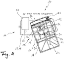
- das Sitz- und/oder Liegemöbel mit einer ausgehend aus der Grundstellung gemäß
Fig. 2 um 20° entgegen dem Uhrzeigersinn gedrehten Sitzeinheit zeigt. - Die
Fig. 1 zeigt das erfindungsgemäße Sitz- und/oder Liegemöbel 10 in einer Seitenansicht. Das Sitz- und/oder Liegemöbel 10 umfasst eine einzige Sitzeinheit 12, sowie eine Unterkonstruktion 14, auf der die Sitzeinheit 12 drehbar ruht. Die Sitzeinheit 12 selbst umfasst wiederum ein in derFig. 1 durch ein Seiten- bzw. Armlehnenteil 22 verdecktes Sitzteil 16, ein an der Vorderkante 34 des Sitzteils 16 angelenktes Fußteil 18 sowie ein an der Hinterkante 36 des Sitzteils 16 angelenktes Rückenteil 20. Die Neigung des Fußteils 18 sowie des Rückenteils 20 kann somit manuell oder mittels eines motorischen Antriebs verändert werden, um einer auf der Sitzeinheit 12 befindlichen Person größtmöglichen Komfort zu bieten. Auch wenn dies hier der besseren Übersichtlichkeit halber nicht dargestellt ist, können die einzelnen Teile 16, 18, 20, 22 der Sitzeinheit 12 gepolstert ausgebildet sein. - Wie der Zusammenschau der
Fig. 1 und2 entnommen werden kann, weist die Unterkonstruktion 14 voneinander beabstandete kufenartige Standfüße 24 auf, wobei von jedem Standfuß 24 eine Stütze 26 nach oben absteht. Den oberen Abschluss der Unterkonstruktion 14 bildet eine horizontal ausgerichtete ebene Platte 28, welche an dem oberen Ende der jeweiligen Stütze 26 montiert ist. - Bei der hier dargestellten Ausführungsform ist die Sitzeinheit 12 um eine vertikale Achse A mittels eines hier nicht genauer erkennbaren Drehlagers 32 wie beispielsweise einer Drehstütze auf der Unterkonstruktion 14 und insbesondere auf deren ebenen Platte 28 drehbar gelagert. Auch wenn dies hier nicht dargestellt ist, kann die Drehstütze in an sich bekannter Art und Weise beispielsweise eine von der Oberseite der ebenen Platte 28 nach oben abstehende Zylinderhülse aufweisen, die einen von der Unterseite des Sitzteils 16 abstehenden Zylinderzapfen drehbar aufnimmt, sodass die Sitzeinheit 12 um die durch den Zylinderzapfen definierte Achse A gedreht werden kann.
- Da durch das ausgeklappte Fußteil 18 ein nicht unerhebliches Kippmoment auf die Sitzeinheit 12 einwirken kann, ist die Sitzeinheit 12 erfindungsgemäß über zwei Rollen 30 unterhalb des Sitzteils 16 an der Unterkonstruktion 14 und insbesondere auf der Oberfläche der ebenen Platte 28 abgestützt. Bei der hier dargestellten Ausführungsform sind die beiden Rollen 30 an der Unterseite des Sitzteils 16 angebracht, und zwar in einem vorderen Bereich 38 des Sitzteils 16 (siehe
Fig. 2 ), der sich zwischen der Vorderkante 34 des Sitzteils 16 und der vertikalen Achse A erstreckt, um die die Sitzeinheit 12 gedreht werden kann, siehe hierzuFig. 2 . Genauer befinden sich dabei die beiden Rollen 30 etwa in der Mitte des vorderen Bereichs 38 zwischen der Vorderkante 34 und der vertikalen Achse A, wobei sie bezüglich einer Ebene, die die Sitzeinheit 12 in zwei im Wesentlichen gleiche Hälfte unterteilt, spiegelsymmetrisch zueinander angeordnet sind. Die Drehachsen der beiden Rollen verlaufen dabei durch die vertikale Achse A, wobei bei der hier dargestellten Ausführungsform die Drehachsen der beiden Rollen 30 in etwa einen rechten Winkel einschließen. - Durch die beiden Rollen 30 sowie das Drehlager 32 wird somit eine Dreipunktlagerung geschaffen, durch die das aus dem Fußteil 18 resultierende Kippmoment kompensiert werden kann.
- Auch wenn dies bei der hier dargestellten Ausführungsform nicht vorgesehen ist, können an der Unterseite des Sitzteils 16 zwei weitere Rollen befestigt sein, die sich in dem hinteren Bereich 38 zwischen der Hinterkante 36 und der vertikalen Achse A befinden, um so auch Kippmomente, die unter Umständen aus dem Rückenteil 20 resultieren, zuverlässig aufnehmen zu können.
- Wie den
Fig. 2 bis 4 ferner entnommen werden kann, sind auf der Oberfläche der ebenen Platte 28 zwei kreisbogenförmige Laufschienen 42 befestigt, auf denen die jeweilige Rolle 30 aufsteht. Der Mittelpunkt der beiden kreisbogenförmigen Laufschienen 42 fällt dabei mit der vertikalen Achse A zusammen, sodass die Rollen 30 auf den jeweiligen Laufschienen 42 abrollen können, wenn die Sitzeinheit 12 gedreht wird. - Da das Sitz- und/oder Liegemöbel 10 Bestandteil einer größeren Couch sein kann, mit der es über die Unterkonstruktion 14 verbunden ist, ist bei der hier dargestellten Ausführungsform die Sitzeinheit 12 des Sitz- und/oder Liegemöbels 10 um einen Winkel von 40° (+/- 20°) zwischen den beiden in den
Fig. 3 und4 dargestellten Maximalstellungen drehbar. Die Maximalstellungen sind dabei durch jeweils einen Anschlag definiert, durch den verhindert werden kann, dass die Sitzeinheit 12 über die jeweilige Maximalstellung hinaus gedreht werden kann. Durch die Begrenzung der maximalen Drehbarkeit der Sitzeinheit 12 kann dabei sichergestellt werden, dass die Sitzeinheit 12 nicht mit anderen feststehenden Sofateilen kollidieren kann. - Wie der Draufsicht gemäß den
Fig. 2 bis 4 ferner entnommen werden kann, steht die ebene Platte 28 auf einer Seite über das Sitzteil 16 über, wobei dieser überstehende Plattenabschnitt 48 selbst als Ablagefläche dienen kann. Darüber hinaus ist in den seitlich überstehenden Plattenabschnitt 48 eine Steckdose 46 integriert. Ferner trägt der seitlich überstehende Plattenabschnitt 48 eine darüber befindliche Tischplatte 44, die von einer Person auf der Sitzeinheit 12 besonders gut zu erreichen ist, da die Sitzeinheit 12 auf der dieser Tischplatte 44 zugewandten Seite kein Seitenteil aufweist. -
- 10
- Sitz- und/oder Liegemöbel
- 12
- Sitzeinheit
- 14
- Unterkonstruktion
- 16
- Sitzteil
- 18
- Fußteil
- 20
- Rückenteil
- 22
- Seitenteil
- 24
- Standfuß
- 26
- Stütze
- 28
- Ebene Platte
- 30
- Rollen
- 32
- Drehlager
- 34
- Vorderkante
- 36
- Hinterkante
- 38
- Vorderer Bereich
- 40
- Hinterer Bereich
- 42
- Laufschiene
- 44
- Tischplatte
- 46
- Steckdose
- 48
- Überstehender Plattenabschnitt
- A
- Vertikale Achse
Claims (10)
- Sitz- und/oder Liegemöbel (10), mit einer ein Sitzteil (16) und ein Rückenteil (20), vorzugsweise auch ein verschwenkbares Fußteil (18), umfassenden Sitzeinheit (12) und einer Unterkonstruktion (14), auf der die Sitzeinheit (12) um eine vertikale Achse (A) drehbar gelagert ist, wobei die Sitzeinheit (12) zusätzlich über zumindest eine Rolle (30) unterhalb des Sitzteils (16) an der Unterkonstruktion (14) abgestützt ist, wobei die Unterkonstruktion (14) eine unterhalb des Sitzteils (16) befindliche ebene Platte (28) aufweist, auf der die zumindest eine Rolle (30) aufsteht;
dadurch gekennzeichnet, dass
an der ebenen Platte (28) für jede Rolle (30) eine vorzugsweise
bogenförmige Laufschiene (42) befestigt ist, auf der die Rolle (30) aufsteht - Sitz- und/oder Liegemöbel nach Anspruch 1,
dadurch gekennzeichnet, dass
wobei die Sitzeinheit (12) über zwei Rolle (30) unterhalb des Sitzteils (16) an der Unterkonstruktion (14) abgestützt ist. - Sitz- und/oder Liegemöbel nach zumindest einem der vorstehenden Ansprüche,
dadurch gekennzeichnet, dass
die zumindest eine Rolle (30) an dem Sitzteil (16) angebracht ist. - Sitz- und/oder Liegemöbel nach zumindest einem der vorstehenden Ansprüche,
dadurch gekennzeichnet, dass
die zumindest eine Rolle (30) an dem Sitzteil (16) in einem Bereich (38), der sich zwischen einer Vorderkante (34) des Sitzteils (16) und der vertikalen Achse (A) erstreckt, um die die Sitzeinheit (12) drehbar ist, angebracht ist, insbesondere in einem mittleren Abschnitt dieses vorderen Bereichs (38); und/oder
die zumindest eine Rolle (30) an dem Sitzteil (16) in einem Bereich (40), der sich zwischen einer Hinterkante (36) des Sitzteils (16) und der vertikalen Achse (A) erstreckt, um die die Sitzeinheit (12) drehbar ist, angebracht ist, insbesondere in einem mittleren Abschnitt dieses hinteren Bereichs (40). - Sitz- und/oder Liegemöbel nach zumindest einem der vorstehenden Ansprüche,
dadurch gekennzeichnet , dass
die Drehachsen der beiden Rollen (30) einen Winkel von 70 bis 100°, insbesondere einen rechten Winkel, einschließen, wobei es insbesondere vorgesehen ist, dass der Winkel durch eine Ebene, die die Sitzeinheit (12) in zwei im Wesentlichen gleiche Hälften unterteilt, in zwei gleichgroße Winkel unterteilt ist. - Sitz- und/oder Liegemöbel nach zumindest einem der vorstehenden Ansprüche,
dadurch gekennzeichnet, dass
die zumindest Rolle (30) eine Drehachse aufweist, die die vertikale Achse (A) schneidet, um die die Sitzeinheit (12) drehbar ist. - Sitz- und/oder Liegemöbel nach zumindest einem der vorstehenden Ansprüche,
dadurch gekennzeichnet , dass
die Sitzeinheit (12) um einen Winkel von maximal etwa 60°, insbesondere um einen Winkel von maximal etwa 50°, und vorzugsweise um einen Winkel von maximal etwa 40°, zwischen zwei Maximalauslenkungsstellungen drehbar ist, wobei es insbesondere vorgesehen ist, dass das Sitz- und/oder Liegemöbel (10) zwei Anschläge aufweist, durch die die beiden Maximalauslenkungsstellungen definiert sind. - Sitz- und/oder Liegemöbel nach zumindest einem der vorstehenden Ansprüche,
dadurch gekennzeichnet , dass
die Sitzeinheit (12) mittels eines mit der vertikalen Achse (A) ausgerichteten Drehlagers (32) drehbar auf der Unterkonstruktion gelagert ist. - Sitz- und/oder Liegemöbel nach Anspruch 1,
dadurch gekennzeichnet, dass
die ebene Platte (28) gegenüber dem Sitzteil (16) einen seitlich überstehenden Plattenabschnitt (48) aufweist, wobei es insbesondere vorgesehen ist, dass in den seitlich überstehenden Plattenabschnitt (48) eine Steckdose (46) integriert ist und/oder dass der seitlich überstehende Plattenabschnitt (48) eine darüber befindliche Tischplatte (44) trägt. - Sitz- und/oder Liegemöbel gemäß einem der vorstehenden Ansprüche, wobei mit der Unterkonstruktion ein feststehendes Sofateil einer Couch verbunden ist.
Priority Applications (1)
| Application Number | Priority Date | Filing Date | Title |
|---|---|---|---|
| PL19193549T PL3626128T3 (pl) | 2018-09-20 | 2019-08-26 | Obrotowy mebel do siedzenia i/lub leżenia |
Applications Claiming Priority (1)
| Application Number | Priority Date | Filing Date | Title |
|---|---|---|---|
| DE102018123191.1A DE102018123191A1 (de) | 2018-09-20 | 2018-09-20 | Drehbares Sitz- und/oder Liegemöbel |
Publications (2)
| Publication Number | Publication Date |
|---|---|
| EP3626128A1 EP3626128A1 (de) | 2020-03-25 |
| EP3626128B1 true EP3626128B1 (de) | 2021-04-21 |
Family
ID=67766060
Family Applications (1)
| Application Number | Title | Priority Date | Filing Date |
|---|---|---|---|
| EP19193549.3A Active EP3626128B1 (de) | 2018-09-20 | 2019-08-26 | Drehbares sitz- und/oder liegemöbel |
Country Status (5)
| Country | Link |
|---|---|
| EP (1) | EP3626128B1 (de) |
| DE (1) | DE102018123191A1 (de) |
| ES (1) | ES2875941T3 (de) |
| HU (1) | HUE053902T2 (de) |
| PL (1) | PL3626128T3 (de) |
Family Cites Families (4)
| Publication number | Priority date | Publication date | Assignee | Title |
|---|---|---|---|---|
| DE3320989A1 (de) * | 1983-06-10 | 1984-12-13 | Holst, Helmut, 4000 Düsseldorf | Drehbarer sitz, insbesondere fuer kraftfahrzeuge |
| DE19512284C2 (de) * | 1995-04-04 | 1997-03-20 | Grammer Ag | Fahrzeugsitz, insbesondere Staplersitz |
| DE29602157U1 (de) * | 1996-02-08 | 1996-04-11 | Schönbrunner Polstermöbel GmbH, 98667 Schönbrunn | Couch |
| DE29714102U1 (de) * | 1997-08-07 | 1997-11-13 | Krauss und Weinbeer GmbH, 96215 Lichtenfels | Multifunktionales Polstermöbel |
-
2018
- 2018-09-20 DE DE102018123191.1A patent/DE102018123191A1/de not_active Withdrawn
-
2019
- 2019-08-26 HU HUE19193549A patent/HUE053902T2/hu unknown
- 2019-08-26 ES ES19193549T patent/ES2875941T3/es active Active
- 2019-08-26 EP EP19193549.3A patent/EP3626128B1/de active Active
- 2019-08-26 PL PL19193549T patent/PL3626128T3/pl unknown
Non-Patent Citations (1)
| Title |
|---|
| None * |
Also Published As
| Publication number | Publication date |
|---|---|
| HUE053902T2 (hu) | 2021-07-28 |
| DE102018123191A1 (de) | 2020-03-26 |
| ES2875941T3 (es) | 2021-11-11 |
| PL3626128T3 (pl) | 2021-11-02 |
| EP3626128A1 (de) | 2020-03-25 |
Similar Documents
| Publication | Publication Date | Title |
|---|---|---|
| DE10007103A1 (de) | Verstellbarer Arbeitsstuhl, insbesondere Bürostuhl | |
| EP2801293B1 (de) | Sitzmöbelstück und Beschlag hierfür | |
| DE2459908B2 (de) | Ausziehvorrichtung für eine Fußstütze bei einem Lehnsessel | |
| DE69808549T2 (de) | Klapptisch | |
| EP3210496B1 (de) | Tischsystem | |
| DE102005051236A1 (de) | Sessel | |
| EP3045078B1 (de) | Sitzmöbel | |
| EP2544568B1 (de) | Möbelstück und beschlag für ein möbelstück | |
| EP3626128A1 (de) | Drehbares sitz- und/oder liegemöbel | |
| EP2721950B1 (de) | Klappbarer Bistrotisch | |
| DE202005020080U1 (de) | Sitzmöbel mit Rückenlehne und verstellbarer Kopfstütze | |
| DE19635635C1 (de) | Sitzmöbel | |
| EP4138612A1 (de) | Stuhl | |
| DE8612880U1 (de) | Bürotisch | |
| EP0908116B1 (de) | Tisch mit einer Tischplatte | |
| DE202011105595U1 (de) | Sitz- und Fußteilbeschlag | |
| DE202008000366U1 (de) | Seitenkörper für ein Sitz-/Liegemöbel | |
| EP1397982A1 (de) | Mehrzweckstuhl mit einem wegklappbaren Schreibtablar | |
| DE3931167A1 (de) | Tisch-beistelltisch-kombination | |
| DE29908001U1 (de) | Schrankbett | |
| DE29612101U1 (de) | Behandlungsliege | |
| DE19608696C2 (de) | In ein Stehpult wandelbarer Stuhl | |
| DE102010020225A1 (de) | Beschlag zur Verstellung einer Rückenlehne | |
| DE9301401U1 (de) | Vorrichtung zum Verstellen eines beweglichen Möbelteils | |
| DE202006013897U1 (de) | Sitz- und/oder Liegemöbel mit verstellbarer Arm- und/oder Rückenlehne |
Legal Events
| Date | Code | Title | Description |
|---|---|---|---|
| PUAI | Public reference made under article 153(3) epc to a published international application that has entered the european phase |
Free format text: ORIGINAL CODE: 0009012 |
|
| STAA | Information on the status of an ep patent application or granted ep patent |
Free format text: STATUS: THE APPLICATION HAS BEEN PUBLISHED |
|
| AK | Designated contracting states |
Kind code of ref document: A1 Designated state(s): AL AT BE BG CH CY CZ DE DK EE ES FI FR GB GR HR HU IE IS IT LI LT LU LV MC MK MT NL NO PL PT RO RS SE SI SK SM TR |
|
| AX | Request for extension of the european patent |
Extension state: BA ME |
|
| STAA | Information on the status of an ep patent application or granted ep patent |
Free format text: STATUS: REQUEST FOR EXAMINATION WAS MADE |
|
| 17P | Request for examination filed |
Effective date: 20200831 |
|
| RBV | Designated contracting states (corrected) |
Designated state(s): AL AT BE BG CH CY CZ DE DK EE ES FI FR GB GR HR HU IE IS IT LI LT LU LV MC MK MT NL NO PL PT RO RS SE SI SK SM TR |
|
| GRAP | Despatch of communication of intention to grant a patent |
Free format text: ORIGINAL CODE: EPIDOSNIGR1 |
|
| STAA | Information on the status of an ep patent application or granted ep patent |
Free format text: STATUS: GRANT OF PATENT IS INTENDED |
|
| INTG | Intention to grant announced |
Effective date: 20201111 |
|
| GRAS | Grant fee paid |
Free format text: ORIGINAL CODE: EPIDOSNIGR3 |
|
| GRAA | (expected) grant |
Free format text: ORIGINAL CODE: 0009210 |
|
| STAA | Information on the status of an ep patent application or granted ep patent |
Free format text: STATUS: THE PATENT HAS BEEN GRANTED |
|
| AK | Designated contracting states |
Kind code of ref document: B1 Designated state(s): AL AT BE BG CH CY CZ DE DK EE ES FI FR GB GR HR HU IE IS IT LI LT LU LV MC MK MT NL NO PL PT RO RS SE SI SK SM TR |
|
| REG | Reference to a national code |
Ref country code: GB Ref legal event code: FG4D Free format text: NOT ENGLISH |
|
| REG | Reference to a national code |
Ref country code: CH Ref legal event code: EP Ref country code: CH Ref legal event code: NV Representative=s name: INTELLECTUAL PROPERTY SERVICES GMBH, CH |
|
| REG | Reference to a national code |
Ref country code: DE Ref legal event code: R096 Ref document number: 502019001256 Country of ref document: DE |
|
| REG | Reference to a national code |
Ref country code: IE Ref legal event code: FG4D Free format text: LANGUAGE OF EP DOCUMENT: GERMAN |
|
| REG | Reference to a national code |
Ref country code: AT Ref legal event code: REF Ref document number: 1383727 Country of ref document: AT Kind code of ref document: T Effective date: 20210515 |
|
| REG | Reference to a national code |
Ref country code: NL Ref legal event code: FP |
|
| REG | Reference to a national code |
Ref country code: HU Ref legal event code: AG4A Ref document number: E053902 Country of ref document: HU |
|
| REG | Reference to a national code |
Ref country code: LT Ref legal event code: MG9D |
|
| PG25 | Lapsed in a contracting state [announced via postgrant information from national office to epo] |
Ref country code: LT Free format text: LAPSE BECAUSE OF FAILURE TO SUBMIT A TRANSLATION OF THE DESCRIPTION OR TO PAY THE FEE WITHIN THE PRESCRIBED TIME-LIMIT Effective date: 20210421 Ref country code: HR Free format text: LAPSE BECAUSE OF FAILURE TO SUBMIT A TRANSLATION OF THE DESCRIPTION OR TO PAY THE FEE WITHIN THE PRESCRIBED TIME-LIMIT Effective date: 20210421 Ref country code: FI Free format text: LAPSE BECAUSE OF FAILURE TO SUBMIT A TRANSLATION OF THE DESCRIPTION OR TO PAY THE FEE WITHIN THE PRESCRIBED TIME-LIMIT Effective date: 20210421 Ref country code: BG Free format text: LAPSE BECAUSE OF FAILURE TO SUBMIT A TRANSLATION OF THE DESCRIPTION OR TO PAY THE FEE WITHIN THE PRESCRIBED TIME-LIMIT Effective date: 20210721 |
|
| REG | Reference to a national code |
Ref country code: ES Ref legal event code: FG2A Ref document number: 2875941 Country of ref document: ES Kind code of ref document: T3 Effective date: 20211111 |
|
| PG25 | Lapsed in a contracting state [announced via postgrant information from national office to epo] |
Ref country code: LV Free format text: LAPSE BECAUSE OF FAILURE TO SUBMIT A TRANSLATION OF THE DESCRIPTION OR TO PAY THE FEE WITHIN THE PRESCRIBED TIME-LIMIT Effective date: 20210421 Ref country code: NO Free format text: LAPSE BECAUSE OF FAILURE TO SUBMIT A TRANSLATION OF THE DESCRIPTION OR TO PAY THE FEE WITHIN THE PRESCRIBED TIME-LIMIT Effective date: 20210721 Ref country code: SE Free format text: LAPSE BECAUSE OF FAILURE TO SUBMIT A TRANSLATION OF THE DESCRIPTION OR TO PAY THE FEE WITHIN THE PRESCRIBED TIME-LIMIT Effective date: 20210421 Ref country code: RS Free format text: LAPSE BECAUSE OF FAILURE TO SUBMIT A TRANSLATION OF THE DESCRIPTION OR TO PAY THE FEE WITHIN THE PRESCRIBED TIME-LIMIT Effective date: 20210421 Ref country code: PT Free format text: LAPSE BECAUSE OF FAILURE TO SUBMIT A TRANSLATION OF THE DESCRIPTION OR TO PAY THE FEE WITHIN THE PRESCRIBED TIME-LIMIT Effective date: 20210823 Ref country code: GR Free format text: LAPSE BECAUSE OF FAILURE TO SUBMIT A TRANSLATION OF THE DESCRIPTION OR TO PAY THE FEE WITHIN THE PRESCRIBED TIME-LIMIT Effective date: 20210722 Ref country code: IS Free format text: LAPSE BECAUSE OF FAILURE TO SUBMIT A TRANSLATION OF THE DESCRIPTION OR TO PAY THE FEE WITHIN THE PRESCRIBED TIME-LIMIT Effective date: 20210821 |
|
| REG | Reference to a national code |
Ref country code: DE Ref legal event code: R097 Ref document number: 502019001256 Country of ref document: DE |
|
| PG25 | Lapsed in a contracting state [announced via postgrant information from national office to epo] |
Ref country code: EE Free format text: LAPSE BECAUSE OF FAILURE TO SUBMIT A TRANSLATION OF THE DESCRIPTION OR TO PAY THE FEE WITHIN THE PRESCRIBED TIME-LIMIT Effective date: 20210421 Ref country code: SK Free format text: LAPSE BECAUSE OF FAILURE TO SUBMIT A TRANSLATION OF THE DESCRIPTION OR TO PAY THE FEE WITHIN THE PRESCRIBED TIME-LIMIT Effective date: 20210421 Ref country code: RO Free format text: LAPSE BECAUSE OF FAILURE TO SUBMIT A TRANSLATION OF THE DESCRIPTION OR TO PAY THE FEE WITHIN THE PRESCRIBED TIME-LIMIT Effective date: 20210421 Ref country code: SM Free format text: LAPSE BECAUSE OF FAILURE TO SUBMIT A TRANSLATION OF THE DESCRIPTION OR TO PAY THE FEE WITHIN THE PRESCRIBED TIME-LIMIT Effective date: 20210421 Ref country code: DK Free format text: LAPSE BECAUSE OF FAILURE TO SUBMIT A TRANSLATION OF THE DESCRIPTION OR TO PAY THE FEE WITHIN THE PRESCRIBED TIME-LIMIT Effective date: 20210421 Ref country code: CZ Free format text: LAPSE BECAUSE OF FAILURE TO SUBMIT A TRANSLATION OF THE DESCRIPTION OR TO PAY THE FEE WITHIN THE PRESCRIBED TIME-LIMIT Effective date: 20210421 |
|
| PLBE | No opposition filed within time limit |
Free format text: ORIGINAL CODE: 0009261 |
|
| STAA | Information on the status of an ep patent application or granted ep patent |
Free format text: STATUS: NO OPPOSITION FILED WITHIN TIME LIMIT |
|
| 26N | No opposition filed |
Effective date: 20220124 |
|
| PG25 | Lapsed in a contracting state [announced via postgrant information from national office to epo] |
Ref country code: MC Free format text: LAPSE BECAUSE OF FAILURE TO SUBMIT A TRANSLATION OF THE DESCRIPTION OR TO PAY THE FEE WITHIN THE PRESCRIBED TIME-LIMIT Effective date: 20210421 |
|
| PG25 | Lapsed in a contracting state [announced via postgrant information from national office to epo] |
Ref country code: IS Free format text: LAPSE BECAUSE OF FAILURE TO SUBMIT A TRANSLATION OF THE DESCRIPTION OR TO PAY THE FEE WITHIN THE PRESCRIBED TIME-LIMIT Effective date: 20210821 Ref country code: LU Free format text: LAPSE BECAUSE OF NON-PAYMENT OF DUE FEES Effective date: 20210826 Ref country code: AL Free format text: LAPSE BECAUSE OF FAILURE TO SUBMIT A TRANSLATION OF THE DESCRIPTION OR TO PAY THE FEE WITHIN THE PRESCRIBED TIME-LIMIT Effective date: 20210421 |
|
| PG25 | Lapsed in a contracting state [announced via postgrant information from national office to epo] |
Ref country code: IE Free format text: LAPSE BECAUSE OF NON-PAYMENT OF DUE FEES Effective date: 20210826 |
|
| PG25 | Lapsed in a contracting state [announced via postgrant information from national office to epo] |
Ref country code: CY Free format text: LAPSE BECAUSE OF FAILURE TO SUBMIT A TRANSLATION OF THE DESCRIPTION OR TO PAY THE FEE WITHIN THE PRESCRIBED TIME-LIMIT Effective date: 20210421 |
|
| PG25 | Lapsed in a contracting state [announced via postgrant information from national office to epo] |
Ref country code: MK Free format text: LAPSE BECAUSE OF FAILURE TO SUBMIT A TRANSLATION OF THE DESCRIPTION OR TO PAY THE FEE WITHIN THE PRESCRIBED TIME-LIMIT Effective date: 20210421 |
|
| PG25 | Lapsed in a contracting state [announced via postgrant information from national office to epo] |
Ref country code: TR Free format text: LAPSE BECAUSE OF FAILURE TO SUBMIT A TRANSLATION OF THE DESCRIPTION OR TO PAY THE FEE WITHIN THE PRESCRIBED TIME-LIMIT Effective date: 20210421 |
|
| PG25 | Lapsed in a contracting state [announced via postgrant information from national office to epo] |
Ref country code: MT Free format text: LAPSE BECAUSE OF FAILURE TO SUBMIT A TRANSLATION OF THE DESCRIPTION OR TO PAY THE FEE WITHIN THE PRESCRIBED TIME-LIMIT Effective date: 20210421 |
|
| PGFP | Annual fee paid to national office [announced via postgrant information from national office to epo] |
Ref country code: NL Payment date: 20250821 Year of fee payment: 7 |
|
| PGFP | Annual fee paid to national office [announced via postgrant information from national office to epo] |
Ref country code: HU Payment date: 20250825 Year of fee payment: 7 |
|
| PGFP | Annual fee paid to national office [announced via postgrant information from national office to epo] |
Ref country code: ES Payment date: 20250926 Year of fee payment: 7 |
|
| PGFP | Annual fee paid to national office [announced via postgrant information from national office to epo] |
Ref country code: PL Payment date: 20250818 Year of fee payment: 7 Ref country code: IT Payment date: 20250825 Year of fee payment: 7 |
|
| PGFP | Annual fee paid to national office [announced via postgrant information from national office to epo] |
Ref country code: BE Payment date: 20250820 Year of fee payment: 7 Ref country code: GB Payment date: 20250820 Year of fee payment: 7 |
|
| PGFP | Annual fee paid to national office [announced via postgrant information from national office to epo] |
Ref country code: AT Payment date: 20250821 Year of fee payment: 7 Ref country code: FR Payment date: 20250828 Year of fee payment: 7 |
|
| PGFP | Annual fee paid to national office [announced via postgrant information from national office to epo] |
Ref country code: CH Payment date: 20250901 Year of fee payment: 7 |
|
| PGFP | Annual fee paid to national office [announced via postgrant information from national office to epo] |
Ref country code: DE Payment date: 20251029 Year of fee payment: 7 |