EP3626131A1 - Geformter schaumkörper - Google Patents
Geformter schaumkörper Download PDFInfo
- Publication number
- EP3626131A1 EP3626131A1 EP18801982.2A EP18801982A EP3626131A1 EP 3626131 A1 EP3626131 A1 EP 3626131A1 EP 18801982 A EP18801982 A EP 18801982A EP 3626131 A1 EP3626131 A1 EP 3626131A1
- Authority
- EP
- European Patent Office
- Prior art keywords
- right direction
- synthetic resin
- resin material
- gap
- seat surface
- Prior art date
- Legal status (The legal status is an assumption and is not a legal conclusion. Google has not performed a legal analysis and makes no representation as to the accuracy of the status listed.)
- Withdrawn
Links
- 239000013518 molded foam Substances 0.000 title claims description 62
- 239000000463 material Substances 0.000 claims abstract description 126
- 229920003002 synthetic resin Polymers 0.000 claims abstract description 124
- 239000000057 synthetic resin Substances 0.000 claims abstract description 124
- 210000000689 upper leg Anatomy 0.000 claims abstract description 39
- 239000006260 foam Substances 0.000 claims description 30
- 230000004308 accommodation Effects 0.000 claims description 3
- 210000001624 hip Anatomy 0.000 description 50
- 238000000465 moulding Methods 0.000 description 7
- 238000010097 foam moulding Methods 0.000 description 6
- 238000005187 foaming Methods 0.000 description 3
- UPMLOUAZCHDJJD-UHFFFAOYSA-N 4,4'-Diphenylmethane Diisocyanate Chemical compound C1=CC(N=C=O)=CC=C1CC1=CC=C(N=C=O)C=C1 UPMLOUAZCHDJJD-UHFFFAOYSA-N 0.000 description 2
- 230000015572 biosynthetic process Effects 0.000 description 2
- 239000000470 constituent Substances 0.000 description 2
- 230000007423 decrease Effects 0.000 description 2
- 230000000694 effects Effects 0.000 description 2
- 238000000034 method Methods 0.000 description 2
- 229910000838 Al alloy Inorganic materials 0.000 description 1
- 239000012790 adhesive layer Substances 0.000 description 1
- 239000003054 catalyst Substances 0.000 description 1
- 230000000052 comparative effect Effects 0.000 description 1
- 239000003431 cross linking reagent Substances 0.000 description 1
- 239000004088 foaming agent Substances 0.000 description 1
- 210000004394 hip joint Anatomy 0.000 description 1
- 229920001228 polyisocyanate Polymers 0.000 description 1
- 239000005056 polyisocyanate Substances 0.000 description 1
- 229920005862 polyol Polymers 0.000 description 1
- 150000003077 polyols Chemical class 0.000 description 1
- 229920005989 resin Polymers 0.000 description 1
- 239000011347 resin Substances 0.000 description 1
- 238000012795 verification Methods 0.000 description 1
Images



Classifications
-
- B—PERFORMING OPERATIONS; TRANSPORTING
- B29—WORKING OF PLASTICS; WORKING OF SUBSTANCES IN A PLASTIC STATE IN GENERAL
- B29C—SHAPING OR JOINING OF PLASTICS; SHAPING OF MATERIAL IN A PLASTIC STATE, NOT OTHERWISE PROVIDED FOR; AFTER-TREATMENT OF THE SHAPED PRODUCTS, e.g. REPAIRING
- B29C44/00—Shaping by internal pressure generated in the material, e.g. swelling or foaming ; Producing porous or cellular expanded plastics articles
- B29C44/02—Shaping by internal pressure generated in the material, e.g. swelling or foaming ; Producing porous or cellular expanded plastics articles for articles of definite length, i.e. discrete articles
- B29C44/04—Shaping by internal pressure generated in the material, e.g. swelling or foaming ; Producing porous or cellular expanded plastics articles for articles of definite length, i.e. discrete articles consisting of at least two parts of chemically or physically different materials, e.g. having different densities
- B29C44/0461—Shaping by internal pressure generated in the material, e.g. swelling or foaming ; Producing porous or cellular expanded plastics articles for articles of definite length, i.e. discrete articles consisting of at least two parts of chemically or physically different materials, e.g. having different densities by having different chemical compositions in different places, e.g. having different concentrations of foaming agent, feeding one composition after the other
-
- B—PERFORMING OPERATIONS; TRANSPORTING
- B60—VEHICLES IN GENERAL
- B60N—SEATS SPECIALLY ADAPTED FOR VEHICLES; VEHICLE PASSENGER ACCOMMODATION NOT OTHERWISE PROVIDED FOR
- B60N2/00—Seats specially adapted for vehicles; Arrangement or mounting of seats in vehicles
- B60N2/70—Upholstery springs ; Upholstery
-
- A—HUMAN NECESSITIES
- A47—FURNITURE; DOMESTIC ARTICLES OR APPLIANCES; COFFEE MILLS; SPICE MILLS; SUCTION CLEANERS IN GENERAL
- A47C—CHAIRS; SOFAS; BEDS
- A47C27/00—Spring, stuffed or fluid mattresses or cushions specially adapted for chairs, beds or sofas
- A47C27/14—Spring, stuffed or fluid mattresses or cushions specially adapted for chairs, beds or sofas with foamed material inlays
- A47C27/148—Spring, stuffed or fluid mattresses or cushions specially adapted for chairs, beds or sofas with foamed material inlays of different resilience
-
- A—HUMAN NECESSITIES
- A47—FURNITURE; DOMESTIC ARTICLES OR APPLIANCES; COFFEE MILLS; SPICE MILLS; SUCTION CLEANERS IN GENERAL
- A47C—CHAIRS; SOFAS; BEDS
- A47C7/00—Parts, details, or accessories of chairs or stools
- A47C7/02—Seat parts
- A47C7/029—Seat parts of non-adjustable shape adapted to a user contour or ergonomic seating positions
-
- A—HUMAN NECESSITIES
- A47—FURNITURE; DOMESTIC ARTICLES OR APPLIANCES; COFFEE MILLS; SPICE MILLS; SUCTION CLEANERS IN GENERAL
- A47C—CHAIRS; SOFAS; BEDS
- A47C7/00—Parts, details, or accessories of chairs or stools
- A47C7/02—Seat parts
- A47C7/18—Seat parts having foamed material included in cushioning part
-
- B—PERFORMING OPERATIONS; TRANSPORTING
- B29—WORKING OF PLASTICS; WORKING OF SUBSTANCES IN A PLASTIC STATE IN GENERAL
- B29C—SHAPING OR JOINING OF PLASTICS; SHAPING OF MATERIAL IN A PLASTIC STATE, NOT OTHERWISE PROVIDED FOR; AFTER-TREATMENT OF THE SHAPED PRODUCTS, e.g. REPAIRING
- B29C44/00—Shaping by internal pressure generated in the material, e.g. swelling or foaming ; Producing porous or cellular expanded plastics articles
- B29C44/02—Shaping by internal pressure generated in the material, e.g. swelling or foaming ; Producing porous or cellular expanded plastics articles for articles of definite length, i.e. discrete articles
- B29C44/04—Shaping by internal pressure generated in the material, e.g. swelling or foaming ; Producing porous or cellular expanded plastics articles for articles of definite length, i.e. discrete articles consisting of at least two parts of chemically or physically different materials, e.g. having different densities
-
- B—PERFORMING OPERATIONS; TRANSPORTING
- B29—WORKING OF PLASTICS; WORKING OF SUBSTANCES IN A PLASTIC STATE IN GENERAL
- B29C—SHAPING OR JOINING OF PLASTICS; SHAPING OF MATERIAL IN A PLASTIC STATE, NOT OTHERWISE PROVIDED FOR; AFTER-TREATMENT OF THE SHAPED PRODUCTS, e.g. REPAIRING
- B29C44/00—Shaping by internal pressure generated in the material, e.g. swelling or foaming ; Producing porous or cellular expanded plastics articles
- B29C44/02—Shaping by internal pressure generated in the material, e.g. swelling or foaming ; Producing porous or cellular expanded plastics articles for articles of definite length, i.e. discrete articles
- B29C44/08—Shaping by internal pressure generated in the material, e.g. swelling or foaming ; Producing porous or cellular expanded plastics articles for articles of definite length, i.e. discrete articles using several expanding or moulding steps
-
- B—PERFORMING OPERATIONS; TRANSPORTING
- B29—WORKING OF PLASTICS; WORKING OF SUBSTANCES IN A PLASTIC STATE IN GENERAL
- B29D—PRODUCING PARTICULAR ARTICLES FROM PLASTICS OR FROM SUBSTANCES IN A PLASTIC STATE
- B29D99/00—Subject matter not provided for in other groups of this subclass
- B29D99/0092—Producing upholstery articles, e.g. cushions, seats
-
- B—PERFORMING OPERATIONS; TRANSPORTING
- B60—VEHICLES IN GENERAL
- B60N—SEATS SPECIALLY ADAPTED FOR VEHICLES; VEHICLE PASSENGER ACCOMMODATION NOT OTHERWISE PROVIDED FOR
- B60N2/00—Seats specially adapted for vehicles; Arrangement or mounting of seats in vehicles
- B60N2/70—Upholstery springs ; Upholstery
- B60N2/7017—Upholstery springs ; Upholstery characterised by the manufacturing process; manufacturing upholstery or upholstery springs not otherwise provided for
-
- A—HUMAN NECESSITIES
- A47—FURNITURE; DOMESTIC ARTICLES OR APPLIANCES; COFFEE MILLS; SPICE MILLS; SUCTION CLEANERS IN GENERAL
- A47C—CHAIRS; SOFAS; BEDS
- A47C27/00—Spring, stuffed or fluid mattresses or cushions specially adapted for chairs, beds or sofas
- A47C27/14—Spring, stuffed or fluid mattresses or cushions specially adapted for chairs, beds or sofas with foamed material inlays
-
- A—HUMAN NECESSITIES
- A47—FURNITURE; DOMESTIC ARTICLES OR APPLIANCES; COFFEE MILLS; SPICE MILLS; SUCTION CLEANERS IN GENERAL
- A47C—CHAIRS; SOFAS; BEDS
- A47C27/00—Spring, stuffed or fluid mattresses or cushions specially adapted for chairs, beds or sofas
- A47C27/14—Spring, stuffed or fluid mattresses or cushions specially adapted for chairs, beds or sofas with foamed material inlays
- A47C27/142—Spring, stuffed or fluid mattresses or cushions specially adapted for chairs, beds or sofas with foamed material inlays with projections, depressions or cavities
-
- A—HUMAN NECESSITIES
- A47—FURNITURE; DOMESTIC ARTICLES OR APPLIANCES; COFFEE MILLS; SPICE MILLS; SUCTION CLEANERS IN GENERAL
- A47C—CHAIRS; SOFAS; BEDS
- A47C27/00—Spring, stuffed or fluid mattresses or cushions specially adapted for chairs, beds or sofas
- A47C27/14—Spring, stuffed or fluid mattresses or cushions specially adapted for chairs, beds or sofas with foamed material inlays
- A47C27/15—Spring, stuffed or fluid mattresses or cushions specially adapted for chairs, beds or sofas with foamed material inlays consisting of two or more layers
-
- A—HUMAN NECESSITIES
- A47—FURNITURE; DOMESTIC ARTICLES OR APPLIANCES; COFFEE MILLS; SPICE MILLS; SUCTION CLEANERS IN GENERAL
- A47C—CHAIRS; SOFAS; BEDS
- A47C27/00—Spring, stuffed or fluid mattresses or cushions specially adapted for chairs, beds or sofas
- A47C27/14—Spring, stuffed or fluid mattresses or cushions specially adapted for chairs, beds or sofas with foamed material inlays
- A47C27/16—Spring, stuffed or fluid mattresses or cushions specially adapted for chairs, beds or sofas with foamed material inlays reinforced with sheet-like or rigid elements, e.g. profiled
-
- B—PERFORMING OPERATIONS; TRANSPORTING
- B29—WORKING OF PLASTICS; WORKING OF SUBSTANCES IN A PLASTIC STATE IN GENERAL
- B29C—SHAPING OR JOINING OF PLASTICS; SHAPING OF MATERIAL IN A PLASTIC STATE, NOT OTHERWISE PROVIDED FOR; AFTER-TREATMENT OF THE SHAPED PRODUCTS, e.g. REPAIRING
- B29C44/00—Shaping by internal pressure generated in the material, e.g. swelling or foaming ; Producing porous or cellular expanded plastics articles
- B29C44/34—Auxiliary operations
- B29C44/58—Moulds
-
- B—PERFORMING OPERATIONS; TRANSPORTING
- B29—WORKING OF PLASTICS; WORKING OF SUBSTANCES IN A PLASTIC STATE IN GENERAL
- B29K—INDEXING SCHEME ASSOCIATED WITH SUBCLASSES B29B, B29C OR B29D, RELATING TO MOULDING MATERIALS OR TO MATERIALS FOR MOULDS, REINFORCEMENTS, FILLERS OR PREFORMED PARTS, e.g. INSERTS
- B29K2075/00—Use of PU, i.e. polyureas or polyurethanes or derivatives thereof, as moulding material
-
- B—PERFORMING OPERATIONS; TRANSPORTING
- B29—WORKING OF PLASTICS; WORKING OF SUBSTANCES IN A PLASTIC STATE IN GENERAL
- B29K—INDEXING SCHEME ASSOCIATED WITH SUBCLASSES B29B, B29C OR B29D, RELATING TO MOULDING MATERIALS OR TO MATERIALS FOR MOULDS, REINFORCEMENTS, FILLERS OR PREFORMED PARTS, e.g. INSERTS
- B29K2105/00—Condition, form or state of moulded material or of the material to be shaped
- B29K2105/04—Condition, form or state of moulded material or of the material to be shaped cellular or porous
-
- B—PERFORMING OPERATIONS; TRANSPORTING
- B29—WORKING OF PLASTICS; WORKING OF SUBSTANCES IN A PLASTIC STATE IN GENERAL
- B29L—INDEXING SCHEME ASSOCIATED WITH SUBCLASS B29C, RELATING TO PARTICULAR ARTICLES
- B29L2031/00—Other particular articles
- B29L2031/58—Upholstery or cushions, e.g. vehicle upholstery or interior padding
-
- B—PERFORMING OPERATIONS; TRANSPORTING
- B29—WORKING OF PLASTICS; WORKING OF SUBSTANCES IN A PLASTIC STATE IN GENERAL
- B29L—INDEXING SCHEME ASSOCIATED WITH SUBCLASS B29C, RELATING TO PARTICULAR ARTICLES
- B29L2031/00—Other particular articles
- B29L2031/771—Seats
-
- B—PERFORMING OPERATIONS; TRANSPORTING
- B60—VEHICLES IN GENERAL
- B60N—SEATS SPECIALLY ADAPTED FOR VEHICLES; VEHICLE PASSENGER ACCOMMODATION NOT OTHERWISE PROVIDED FOR
- B60N2205/00—General mechanical or structural details
- B60N2205/30—Seat or seat parts characterised by comprising plural parts or pieces
Definitions
- the present invention relates to a molded foam body.
- a configuration in which a thigh rest part that is positioned on a front part and supports the thighs of an occupants and a hip rest part that extends rearward from a rear end part of the thigh rest part and supports the hips of the occupant are provided has become known as a molded foam body that has a seat surface on which the occupant is seated and is formed of a foam of a synthetic resin material.
- a molded foam body of that type for example, a configuration in which the entire upper part of a seat surface side is formed of a first synthetic resin material, both sides of the lower part on the side opposite to the seat surface in the left-right direction is formed of a second synthetic resin material that is harder than the first synthetic resin material, and a middle part between the sides in the left-right direction is formed of the first synthetic resin material and integrated with the upper part as disclosed in Patent Document 1 is known.
- Patent Document 1 Japanese Unexamined Patent Application, First Publication No. 2009-107131
- the invention takes the above circumstances into consideration, and an object of the present invention is to provide a molded foam body that can mitigate rocking of an occupant when a lateral load or the like is applied.
- a molded foam body of the present invention is a molded foam body which has a seat surface on which an occupant is seated, is formed of a foam of a synthetic resin material, and has a thigh rest part that is positioned on a front part and supports thighs of the occupant, and a hip rest part that extends rearward from a rear end part of the thigh rest part and supports hips of the occupant, in which the molded foam body is formed of a first synthetic resin material and a second synthetic resin material that has higher hardness than the first synthetic resin material, an entire upper part on the seat surface side is formed of the first synthetic resin material, both sides of a lower part that are positioned opposite to the seat surface in a left-right direction are formed of the second synthetic resin material, and a middle part positioned between both sides in the left-right direction is formed of the first synthetic resin material and integrated with the upper part, a pair of left and right second synthetic resin materials forming the lower part have a rear part that is positioned in the hip rest part and a front
- a molded foam body 10 includes a body part 12 formed of a foam of a first synthetic resin material and a foam of a second synthetic resin material that is harder than the first synthetic resin material, a pair of left and right side parts 11 that are connected to both sides of the body part 12 in the left-right direction X and are formed of a foam of the second synthetic resin material, an attachment part 13 projecting rearward integrally from the body part 12 and the side parts 11, and a seat surface 10a on which an occupant is seated.
- First boundary grooves 10d extending in a front-rear direction Y are separately formed on the seat surface 10a at the boundaries between the pair of the side parts 11 and the body part 12, and a second boundary groove 10e extending in the left-right direction X is formed at the boundary between the body part 12 and the attachment part 13.
- the first boundary grooves 10d and the second boundary groove 10e have fixtures attached to fix a covering sheet to the molded foam body 10.
- the attachment part 13 is disposed immediately below a lower end part of a backrest part, which is not shown.
- the foam of the first synthetic resin material and the foam of the second synthetic resin material are obtained by foam-molding an undiluted foam solution containing a polyol, a polyisocyanate, for example, methylene diphenyl diisocyanate (MDI), or the like, a crosslinking agent, a foaming agent, and a catalyst.
- the hardness of the second synthetic resin material is, for example, 1.2 times or more and 3.5 times or less a hardness of the first synthetic resin material.
- the hardness of the first synthetic resin material is, for example, about 180 N to 500 N, and the hardness of the second synthetic resin material is, for example, about 200 N to 600 N.
- a pressure plate is moved forward to the molded foam body 10 at a speed of 50 mm/min until a reaction force that the pressure plate receives reaches 4.9 N, and the position of the pressure plate is set as an initial position where the thickness of the molded foam body 10 is 100%.
- the pressure plate is a circular plate having a diameter of 200 mm, and a receiving plate of the molded foam body 10 that supports the back surface positioned opposite to the seat surface 10a has through holes having a diameter of 6 mm which are formed at a pitch of 19 mm.
- the surface shape of the receiving plate is the same as the back surface shape of the molded foam body 10.
- the pressure plate positioned at the initial position is moved forward to the molded foam body 10 at a speed of 50 mm/min, and when the thickness of the molded foam body 10 is reduced to 75%, the pressure plate is quickly moved backward to a position at which the molded foam body 10 does not receive a reaction force. Then, after waiting for 60 seconds, the pressure plate is moved forward to the molded foam body 10 at the speed of 50 mm/min again and the pressure plate is stopped at a position where the thickness of the molded foam body 10 is reduced to 75%. Then, the reaction force that the pressure plate receives after waiting for 20 seconds is determined and the value is set as the hardness.
- the body part 12 includes a thigh rest part 14 that is positioned on the front part and supports the thighs of an occupant, a hip rest part 15 that extends rearward from a rear end part of the thigh rest part 14 and supports the hips of the occupant, and a non-contact part 16 that connects a rear end part of the hip rest part 15 to the attachment part 13 as shown in Fig. 1 .
- the non-contact part 16 is an inner part of the body part 12 with which an occupant does not come in contact when the occupant sits on the seat surface 10a since the waist of the occupant does not go deep into the rear end part of the body part 12 due to, for example, a backrest part, which is not shown.
- the non-contact part 16 is a part of the body part 12 with which, for example, a three-dimensional model, which is used in defining automobile seating accommodation (3DM-JM50) prescribed in the Japanese Industrial Standards JIS D4607-1977 (which will be referred to as a "model") and is set to weigh 50 kg, does not come in contact when the model is placed on the seat surface 10a.
- the hatched part on the seat surface 10a shown in Fig. 1 indicates a contact region Z of the seat surface 10a with which the model comes in contact when the model is placed on the seat surface 10a.
- the rear end part of the contact region Z has a curved shape projecting rearward in a plan view of the seat surface 10a.
- the non-contact part 16 is a part of the body part 12 positioned behind the contact region Z. A front edge of the non-contact part 16 is aligned with a line, which is not shown, passing through a rear edge of the contact region Z and extending in the left-right direction X.
- the hip point HP of the model placed on the seat surface 10a that is, a connection part of the trunk and the thighs (hip joint), is positioned in the contact region Z. Further, a front edge of the hip rest part 15 is positioned about 100 mm in front of the hip point HP.
- an entire upper part 12a of the body part 12 on the seat surface 10a side is formed of the first synthetic resin material.
- Both sides of a lower part 12b of the body part 12 in the left-right direction X, which is positioned opposite to the seat surface 10a, is formed of the second synthetic resin material and integrated with the side parts 11, and a middle part positioned between both sides in the left-right direction X is formed of the first synthetic resin material and integrated with the upper part 12a.
- the first synthetic resin material forming the lower part 12b of the body part 12 and the second synthetic resin material adhere directly to each other without having an adhesive layer therebetween.
- a pair of left and right second synthetic resin materials forming the lower part 12b of the body part 12 includes a rear part 17 that is positioned in the hip rest part 15 and a front part 18 that is connected to a front end of the rear part 17 and at least a front end part of which is positioned in the thigh rest part 14 as shown in Fig. 1 .
- a contour L indicating an outer circumferential surface of the model placed on the seat surface 10a, that is, a surface that is orthogonal to the top-bottom direction and directed in the horizontal direction including the left-right direction X and the front-rear direction Y in the plan view of the seat surface 10a as shown in Fig. 1
- the rear part 17 extends inward in the left-right direction X
- the front part 18 is positioned outside in the left-right direction X.
- An inner edge 17a of the rear part 17 in the left-right direction X has a curved shape projecting inward the left-right direction X in the plan view of the seat surface 10a.
- the front half part of the rear part 17 is positioned in the hip rest part 15 and the rear half part thereof is positioned in the non-contact part 16.
- the entire rear part 17 except for the rear end part thereof projects inward from the contour L in left-right direction X.
- a front edge of the rear part 17 is positioned on the front edge of the hip rest part 15 on the contour L. Further, the front edge of the rear part 17 may be set to be positioned in the thigh rest part 14 or behind the front edge of the hip rest part 15.
- a part of the rear part 17 crosses, in the front-rear direction Y, the position at which the hip point HP is positioned in the front-rear direction Y (which will be referred to as an HP position) and overlaps a part of the contact region Z that is positioned in the hip rest part 15 in the plan view of the seat surface 10a.
- the part of the rear part 17 is an inner end part of the front half part of the rear part 17 in the left-right direction X.
- the entire front part 18 is positioned outside the contour L in the left-right direction X.
- the front end part of the front part 18 is positioned in the thigh rest part 14 and the part behind the front end part is positioned in the hip rest part 15.
- the front half part of the front part 18 is positioned in the thigh rest part 14, and the rear half part thereof is positioned in the hip rest part 15.
- the thigh rest part 14 starts from a part about 150 mm in front of the HP position and ends at a part about 250 mm in front of the HP position in the body part 12.
- An inner edge 18a of the front part 18 in the left-right direction X gradually extends outward in the left-right direction X from the rear side to the front side.
- the inner edge 18a of the front part 18 in the left-right direction X has a curved shape that is recessed outward in the left-right direction X in the plan view of the seat surface 10a.
- the plane area of the part surrounded by the inner edge 17a of the rear part 17 in the left-right direction X and the contour L is larger than the plane area of the part sandwiched by the inner edge 18a of the front part 18 in the left-right direction X and the contour L in the left-right direction X.
- an auxiliary line K connecting the front edge of the front part 18 and the contour L in the left-right direction X is given in Fig. 1 , and in this case, the latter plane area refers to the plane area surrounded by the auxiliary line K, the inner edge 18a of the front part 18 in the left-right direction X, and the contour L.
- Each of the plane areas is larger than the plane area of the overlapping part of the rear part 17 and the contact region Z in the plan view of the seat surface 10a.
- a part of the pair of left and right second synthetic resin materials forming the lower part 12b of the body part 12 having a maximum gap therebetween in the left-right direction X is positioned in the thigh rest part 14, and a part thereof having a minimum gap is positioned in the hip rest part 15.
- the gap between the pair of left and right second synthetic resin materials forming the lower part 12b of the body part 12 in the left-right direction X becomes a maximum at the front end part of the front part 18 and becomes a minimum at the HP position.
- the maximum value W1 of the gap between the pair of left and right second synthetic resin materials forming the lower part 12b of the body part 12 in the left-right direction X is two times or more and three times or less the minimum value W2 of the gap in the left-right direction X.
- a length W3 of the contour L in the left-right direction X is shorter than the maximum value W1 and longer than the minimum value W2.
- the gap between the pair of left and right second synthetic resin materials forming the lower part 12b of the body part 12 in the left-right direction X smoothly changes rearward from the front end part of the front part 18 without a step.
- the gap between the pair of left and right second synthetic resin materials forming the lower part 12b of the body part 12 in the left-right direction X gradually decreases from the front end part of the front part 18 at which the gap becomes a maximum toward the HP position at which the gap becomes a minimum.
- parts at which the gap between the pair of left and right second synthetic resin materials forming the lower part 12b of the body part 12 in the left-right direction X becomes a maximum or minimum are not limited to the front end part of the front part 18 and the HP position, and may be appropriately changed.
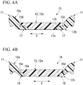
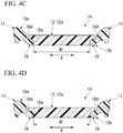
- the gap between the pair of left and right second synthetic resin materials forming the lower part 12b of the body part 12 in the left-right direction X is, for example, about 110 mm (the minimum value W2) at the HP position ( Fig. 3A ), about 120 mm at the position about 30 mm behind the HP position ( Fig. 2C ), about 140 mm at the position about 60 mm behind the HP position ( Fig. 2B ), about 150 mm at the position about 90 mm behind the HP position ( Fig. 2A ), about 120 mm at the position about 30 mm in front of the HP position ( Fig. 3B ), about 140 mm at the position about 60 mm in front of the HP position ( Fig.
- a front end part among both end parts of the attachment part 13 in the left-right direction X positioned at the lower part that is positioned opposite to the seat surface 10a is formed of the second synthetic resin material, and all other parts except this part are formed of the first synthetic resin material.
- the embodiment is not limited thereto, and for example, the front end part among both end parts at the lower part of the attachment part 13 in the left-right direction X may be formed of the first synthetic resin material, all other parts except this part may be formed of the second synthetic resin material, and the attachment part 13 may be formed of another resin material other than the first synthetic resin material and the second synthetic resin material.
- horizontal grooves 19 extending in the left-right direction X are formed in parts of the side parts 11 adjacent to the non-contact part 16 of the body part 12 in the left-right direction X.
- a width of the horizontal grooves 19 is narrower than the width of each of the first boundary grooves 10d and the second boundary groove 10e.
- the horizontal grooves 19 open on the seat surface 10a.
- the depth of the horizontal grooves 19 is deeper than the depth of each of the first boundary grooves 10d and the second boundary groove 10e.
- the horizontal grooves 19 penetrate the side parts 11 in the left-right direction X and open to the first boundary grooves 10d and sides of the surfaces of the side parts 11 facing outward in the left-right direction X.
- the foam molding mold 20 has an upper mold (molding mold) 21 and a lower mold (molding mold) 22, and a pair of left and right side part cavities 23 in which the side parts 11 are molded, a body part cavity 24 in which the body part 12 is molded, and an attachment part cavity 25 in which the attachment part 13 is molded are formed between the upper mold 21 and the lower mold 22 as shown in Fig. 5A and Fig. 5B .
- the surface among inner surfaces of the lower mold 22 that faces upward is a supply surface 22a to which an undiluted foam solution of the first synthetic resin material and an undiluted foam solution of the second synthetic resin material are supplied to mold the seat surface 10a.
- the supply surface 22a includes side-part supply surfaces 23a that define a part of inner surfaces of the side part cavities 23 to which the undiluted foam solution of the second synthetic resin material is supplied and a body-part supply surface 24a that defines a part of inner surfaces of the body part cavity 24 to which the undiluted foam solution of the first synthetic resin material is supplied.
- guiding parts 26 that guide a foam to the body part cavity 24 when the undiluted foam solution of the second synthetic resin material supplied to the side part cavities 23 foams are disposed at the parts adjacent to, in the left-right direction X, a rear end part of the body part cavity 24 in which the non-contact part 16 is molded.
- the guiding parts 26 are provided on the side-part supply surfaces 23a in a standing manner.
- the guiding parts 26 are formed of, for example, an aluminum alloy or the like and integrated with the lower mold 22.
- the guiding parts 26 are formed in a plate shape whose front and rear surfaces face the front-rear direction Y.
- the guiding parts 26 extend in the entire length of the side part cavities 23 in the left-right direction X.
- An amount of each guiding part 26 projecting from the side-part supply surfaces 23a is 50% or more and 90% or less of the gap between an opposite surface 23b facing the side-part supply surface 23a and the side-part supply surface 23a among inner surfaces defining the side part cavities 23.
- An upper edge of each guiding part 26 extends in the left-right direction X along the opposite surface 23b.
- each guiding part 26 is, for example, about 3 mm or more and 5 mm or less. Accordingly, a width of the molded horizontal grooves 19 is restricted, and it is difficult for the horizontal grooves 19 to be able to be visually recognized from outside.
- the guiding parts 26 are, for example, 10 mm or more and 20 mm or less in front of the boundary between the side part cavities 23 and the body part cavity 24, and the attachment part cavity 25.
- a second boundary rib 22c for molding the second boundary groove 10e is disposed on the boundary of the body part cavity 24 and the attachment part cavity 25.
- the guiding parts 26 are 10 mm or more and 20 mm or less in front of the second boundary rib 22c.
- first boundary ribs 22b for molding the first boundary grooves 10d are disposed on the boundaries of the side part cavities 23 and the body part cavity 24.
- the first boundary ribs 22b and the second boundary rib 22c are provided on the supply surface 22a in a standing manner.
- the guiding parts 26 extend outward from the first boundary ribs 22b in the left-right direction X. Upper edges of the inner end parts of the guiding parts 26 in the left-right direction X are connected to upper edges of the first boundary ribs 22b without a step.
- the undiluted foam solution of the second synthetic resin material is supplied to the side-part supply surfaces 23a, and the undiluted foam solution of the first synthetic resin material is supplied to the body-part supply surface 24a (supply step).
- the undiluted foam solution of the second synthetic resin material is supplied to parts of the side part cavities 23 positioned in front of the guiding parts 26.
- the supply surface 22a of the lower mold 22 is sealed with the upper mold 21, and each of the undiluted foam solutions are caused to foam in a mold-clamped state in which the side part cavities 23, the body part cavity 24, and the attachment part cavity 25 are defined between the upper mold 21 and the lower mold 22 (foaming step).
- the undiluted foam solution of the second synthetic resin material reaches the guiding parts 26 in the course of foaming in the side part cavities 23, and the foam is guided inward in the left-right direction X by the guiding parts 26 and enters the body part cavity 24 inward in the left-right direction X.
- the timing at which the undiluted foam solution of the second synthetic resin material is supplied to the side-part supply surfaces 23a and the timing at which the undiluted foam solution of the first synthetic resin material is supplied to the body-part supply surface 24a may be the same or different, and can be appropriately set according to, for example, a foaming speed, a volume, or the like of each of the undiluted foam solutions.
- molding may be performed by supplying the second synthetic resin material to the side-part supply surfaces 23a and then injecting the first synthetic resin material to the body-part supply surface 24a without providing the guiding parts 26.
- the molded foam body 10 of the present embodiment since the plane area of the part surrounded by the inner edge 17a of the rear part 17 in the left-right direction X positioned in the hip rest part 15 and the contour L is greater than the plane area of the part sandwiched by the inner edge 18a of the front part 18 in the left-right direction X and the contour L in the left-right direction X in the plane view of the seat surface 10a as described above, a larger amount of the hard second synthetic resin material is disposed on both sides of a part of the lower part 12b of the body part 12 in the left-right direction X positioned in the hip rest part 15 to which a large load is applied.
- the part of the pair of left and right second synthetic resin materials forming the lower part 12b of the body part 12 at which the gap in the left-right direction X becomes a minimum is positioned in the hip rest part 15 and the maximum value W1 of the gap in the left-right direction X is two times or more the minimum value W2 of the gap in the left-right direction X, a large amount of the hard second synthetic resin material is disposed on both sides of a part of the lower part 12b of the body part 12 in the left-right direction X positioned in the hip rest part 15 to which a large load is applied.
- the hips of the occupant can be reliably held by both sides of the pair of left and right second synthetic resin materials forming the lower part 12b of the body part 12 in the left-right direction X, a difference between degrees of thighs and hip sinking into the molded foam body can be reduced, and thus rocking of the occupant when a lateral load or the like is applied can be mitigated.
- the maximum value W1 of the gap between the pair of left and right second synthetic resin materials forming the lower part 12b of the body part 12 in the left-right direction X is three times or less the minimum value W2 of the gap in the left-right direction X, rocking of the occupant when a lateral load or the like is applied can be more reliably mitigated.
- the gap between the pair of left and right second synthetic resin materials forming the lower part 12b of the body part 12 in the left-right direction X smoothly changes rearward from the front end part of the lower part without a step, it is possible to prevent the generation of a part whose hardness in the top-bottom direction abruptly changes in the front-rear direction Y, and thus discomfort felt by the occupant when he or she is seated can be mitigated.
- the hips of the occupant can be reliably held by both sides of the pair of left and right second synthetic resin materials forming the lower part 12b of the body part 12 in the left-right direction X.
- the side parts 11 are easily displaced inward in the left-right direction X through substantially the entire region in the front-rear direction Y following the downward deflection deformation of the body part 12 when the occupant is seated on the seat surface 10a, and the hips of the occupant can be easily held by the side parts 11 on both sides in the left-right direction X.
- the horizontal grooves 19 are formed in the parts that are hard to visually recognize in the side parts 11 and are adjacent to the non-contact part 16 in the left-right direction X, an unattractive appearance attributable to the formation of the horizontal grooves 19 can be prevented.
- the present invention can also be applied to a molded foam body not having the side parts 11 and the attachment part 13.
- the configuration in which the plane area surrounded by the inner edge 17a of the rear part 17 in the left-right direction X and the contour L is larger than the plane area sandwiched by the inner edge 18a of the front part 18 in the left-right direction X and the contour L in the left-right direction X in the plan view of the seat surface 10a has been introduced in the above-described embodiment, the configuration may be employed if the part of the pair of left and right second synthetic resin materials forming the lower part 12b of the body part 12 at which the gap in the left-right direction X becomes a minimum is positioned in the hip rest part 15 and the maximum value W1 of the gap in the left-right direction X is two times or more the minimum value W2 of the gap in the left-right direction X.
- the configuration in which the part of the pair of left and right second synthetic resin materials forming the lower part 12b of the body part 12 at which the gap in the left-right direction X becomes a minimum is positioned in the hip rest part 15 and the maximum value W1 of the gap in the left-right direction X is two times or more the minimum value W2 of the gap in the left-right direction X has been introduced in the above-described embodiment
- the configuration may be applied if the plane area surrounded by the inner edge 17a of the rear part 17 in the left-right direction X and the contour L is larger than the plane area sandwiched by the inner edge 18a of the front part 18 in the left-right direction X and the contour L in the left-right direction X in the plan view of the seat surface 10a.
- the molded foam body 10 shown in Fig. 1 to Fig. 4B was employed, and as a conventional example, a molded foam body that was formed of the same material as in the example having an the inner edge of the rear part positioned in the hip rest part in the left-right direction substantially extending in the front-rear direction along the contour L ( Fig. 1 ) in a plan view of the seat surface was employed.
- Example and a comparative example the above-described model set to weigh 50 kg was placed on the seat surface for 10 minutes and the sinking degree of the seat surface was measured.
- the sinking degree was measured at two spots including a position about 140 mm behind the HP position (which will be referred to as a hip-side position) and a position about 300 mm in front of the HP position (which will be referred to as a thigh-side position).
- the degree was 4.13 mm at the hip-side position and 0.68 mm at the thigh-side position in the conventional example
- the degree was 3.11 mm at the hip-side position and 2.00 mm at the thigh-side position in Example. That is, while the difference between the sinking degrees at the hip-side position and the thigh-side position was 3.45 mm in the conventional example, the difference was 1.11 mm in Example, and therefore it is ascertained that the difference between the sinking degree of the thighs and the sinking degree of the hip can be reduced.
- the plane area surrounded by the inner edge of the rear part positioned in the hip rest part in the left-right direction and the contour is larger than the plane area sandwiched by the inner edge of the front part in the left-right direction and the contour in the left-right direction in the plan view of the seat surface, a large amount of the hard second synthetic resin material is disposed on both sides of a part of the lower part of the molded foam body in the left-right direction positioned in the hip rest part to which a large load is applied.
- the hips of the occupant can be reliably held by the second synthetic resin material in the left-right direction, a difference between degrees of thighs and hip sinking into the molded foam body can be reduced, and thus rocking of the occupant when a lateral load or the like is applied can be mitigated.
- the entire upper part of the molded foam body that comes in contact with the occupant is formed of the soft first synthetic resin material, satisfactory ride comfort can be exhibited.
- the molded foam body of the present invention is a molded foam body which has a seat surface on which an occupant is seated and is formed of a foam of synthetic resin materials, has a thigh rest part that is positioned on the front part and supports the thighs of the occupant and a hip rest that extends rearward from the rear end part of the thigh rest part and supports the hips of the occupant, is formed of a first synthetic resin material and a second synthetic resin material that is harder than the first synthetic resin material, in which the entire upper part thereof on the seat surface side is formed of the first synthetic resin material, both sides of the lower part that is positioned opposite to the seat surface in the left-right direction is formed of the second synthetic resin material, the middle part positioned between both sides in the left-right direction is formed of the first synthetic resin material and integrated with the upper part, the part of the pair of left and right second synthetic resin materials forming the lower part having the maximum gap therebetween in the left-right direction is positioned in the thigh rest part, the part thereof having a
- the part of the pair of left and right second synthetic resin materials forming the lower part of the molded foam body having the minimum gap in the left-right direction is positioned in the hip rest part and the part thereof having a maximum gap therebetween in the left-right direction is two times or more the minimum value of the gap in the left-right direction, a large amount of the hard second synthetic resin material is disposed on both sides of a part of the lower part of the molded foam body in the left-right direction positioned in the hip rest part to which a large load is applied.
- the hips of the occupant can be reliably held by both sides of the pair of left and right second synthetic resin materials in the left-right direction, a difference between degrees of thighs and hip sinking into the molded foam body can be reduced, and thus rocking of the occupant when a lateral load or the like is applied can be mitigated.
- the part of the pair of left and right second synthetic resin materials forming the lower part having the maximum gap therebetween in the left-right direction may be positioned in the thigh rest part, the part thereof having a minimum gap may be positioned in the hip rest part, and the maximum value of the gap between the pair of left and right second synthetic resin materials forming the lower part in the left-right direction may be two times or more the minimum value of the gap in the left-right direction.
- the maximum value of the gap between the pair of left and right second synthetic resin materials forming the lower part in the left-right direction may be three times or less the minimum value of the gap in the left-right direction.
- the gap between the pair of left and right second synthetic resin materials forming the lower part in the left-right direction may smoothly change rearward from the front end part of the lower part without a step.
- the hardness of the second synthetic resin material may be 1.2 times or more and 3.5 times or less a hardness of the first synthetic resin material.
- the hips of the occupant can be reliably held by both sides of the pair of left and right second synthetic resin materials forming the lower part of the molded foam body in the left-right direction.
- the body part having the thigh rest part and the hip rest part, the pair of left and right side parts that are connected to the body part on both sides in the left-right direction and are formed of a foam of the second synthetic resin material, the attachment part that projects rearward integrally from the body part and the side parts are provided, the body part has a non-contact part that connects the rear end part of the hip rest part and the attachment part, and the horizontal grooves extending in the left-right direction may be formed in the parts of the side parts adjacent to the non-contact part in the left-right direction.
- the horizontal grooves extending in the left-right direction are formed in the parts of the side parts adjacent to the non-contact part of the body part in the left-right direction, the side parts are easily displaced inward in the left-right direction through substantially the entire region in the front-rear direction following the downward deflection deformation of the body part when the occupant is seated on the seat surface, and the hips of the occupant can be easily held by the side parts on both sides in the left-right direction.
- the horizontal grooves are formed in the parts that are hard to visually recognize in the side parts and adjacent to the non-contact part in the left-right direction, an unattractive appearance attributable to the formation of the horizontal grooves can be prevented.
- rocking of an occupant when a lateral load or the like is applied can be mitigated.
Landscapes
- Engineering & Computer Science (AREA)
- Mechanical Engineering (AREA)
- Aviation & Aerospace Engineering (AREA)
- Transportation (AREA)
- Manufacturing & Machinery (AREA)
- Mattresses And Other Support Structures For Chairs And Beds (AREA)
- Seats For Vehicles (AREA)
- Casting Or Compression Moulding Of Plastics Or The Like (AREA)
Applications Claiming Priority (2)
| Application Number | Priority Date | Filing Date | Title |
|---|---|---|---|
| JP2017097437 | 2017-05-16 | ||
| PCT/JP2018/002221 WO2018211744A1 (ja) | 2017-05-16 | 2018-01-25 | 発泡成形体 |
Publications (2)
| Publication Number | Publication Date |
|---|---|
| EP3626131A1 true EP3626131A1 (de) | 2020-03-25 |
| EP3626131A4 EP3626131A4 (de) | 2020-04-22 |
Family
ID=64273563
Family Applications (1)
| Application Number | Title | Priority Date | Filing Date |
|---|---|---|---|
| EP18801982.2A Withdrawn EP3626131A4 (de) | 2017-05-16 | 2018-01-25 | Geformter schaumkörper |
Country Status (5)
| Country | Link |
|---|---|
| US (1) | US10919424B2 (de) |
| EP (1) | EP3626131A4 (de) |
| JP (1) | JP6940602B2 (de) |
| CN (1) | CN110446442B (de) |
| WO (1) | WO2018211744A1 (de) |
Cited By (1)
| Publication number | Priority date | Publication date | Assignee | Title |
|---|---|---|---|---|
| EP3626424A4 (de) * | 2017-05-16 | 2020-06-03 | Bridgestone Corporation | Gussform zur schaumstoffformung und verfahren zur herstellung eines schaumstoffformkörpers |
Families Citing this family (6)
| Publication number | Priority date | Publication date | Assignee | Title |
|---|---|---|---|---|
| JP7039275B2 (ja) * | 2017-12-14 | 2022-03-22 | 株式会社ブリヂストン | 車両用シート、及び、パッド振動特性の調整方法 |
| EP3755296B1 (de) * | 2018-02-27 | 2023-11-01 | Roger Thomas Mascull and Elizabeth Jocelyn Mascull as Trustees of the Rt and EJ Family Trust | Sitzstütze |
| JP2020172211A (ja) * | 2019-04-12 | 2020-10-22 | 株式会社ブリヂストン | 座席シート用のクッション材の製造方法、座席シート用のクッション材、装填体の製造方法、及び、装填体 |
| JP7509075B2 (ja) | 2021-04-23 | 2024-07-02 | トヨタ紡織株式会社 | シート装置 |
| JPWO2023210220A1 (de) * | 2022-04-25 | 2023-11-02 | ||
| US20230371694A1 (en) * | 2022-05-17 | 2023-11-23 | Universal City Studios Llc | Padding system for amusement park attraction system |
Family Cites Families (36)
| Publication number | Priority date | Publication date | Assignee | Title |
|---|---|---|---|---|
| JPS4927362A (de) * | 1972-07-05 | 1974-03-11 | ||
| US3890004A (en) * | 1974-01-16 | 1975-06-17 | Larry E Rail | Body support |
| DE3102140A1 (de) * | 1981-01-23 | 1982-08-19 | Bayer Ag, 5090 Leverkusen | Formteil, insbesondere polster fuer fahrzeugsitze, aus polyurethanschaumstoff mit zonen unterschiedlicher eindruckhaerte und verfahren zu seiner herstellung |
| JPS59500454A (ja) | 1982-03-16 | 1984-03-22 | ジエイ エリツク シ− | 改良型シ−トクツシヨン |
| FR2707972B1 (fr) * | 1993-06-29 | 1995-09-22 | Bfa | Perfectionnements aux matelassures de sièges de véhicules automobiles. |
| US5671492A (en) * | 1995-03-14 | 1997-09-30 | Simon; Keith Douglas | Contoured asymmetrical mattress |
| JPH09140956A (ja) | 1995-11-24 | 1997-06-03 | Bridgestone Corp | ウレタンフォーム成形パッド |
| JP2883032B2 (ja) * | 1995-12-05 | 1999-04-19 | 難波プレス工業株式会社 | 表皮付き多層異硬度座席およびその製造方法 |
| US5913568A (en) * | 1997-09-30 | 1999-06-22 | Brightbill; Stephen T. | Two platform motion seat |
| JP3570497B2 (ja) * | 1999-10-22 | 2004-09-29 | ジョンソン コントロールズ オートモーティブ システムズ株式会社 | シートのクッション体 |
| JP2003289982A (ja) * | 2002-03-29 | 2003-10-14 | Kokuyo Co Ltd | 椅子の座、背凭れ |
| JP2004174762A (ja) * | 2002-11-25 | 2004-06-24 | Toyo Tire & Rubber Co Ltd | シート用パッドの製造方法 |
| JP4634761B2 (ja) * | 2004-08-26 | 2011-02-16 | 株式会社デルタツーリング | シート |
| US20060103225A1 (en) * | 2004-11-15 | 2006-05-18 | Jungin Kim | Ergonomically designed portable seat cushion |
| JP2007125935A (ja) * | 2005-11-01 | 2007-05-24 | Combi Corp | チャイルドシート用クッション |
| JP5189486B2 (ja) * | 2006-03-31 | 2013-04-24 | テイ・エス テック株式会社 | クッション体および座席シートならびにこれらの製造方法 |
| JP2009078142A (ja) * | 2007-09-06 | 2009-04-16 | Bridgestone Corp | 車両用シートパッド及びその製造方法 |
| JP5117161B2 (ja) * | 2007-10-26 | 2013-01-09 | 株式会社イノアックコーポレーション | 発泡成形方法 |
| US7946655B2 (en) * | 2009-06-10 | 2011-05-24 | Hsu Tsung-Yung | Seat cushion structure |
| JP5985411B2 (ja) | 2012-02-22 | 2016-09-06 | トヨタ紡織株式会社 | 車両用シートのクッションパッド |
| US20130257132A1 (en) * | 2012-03-28 | 2013-10-03 | Fu-Chieng Chen | Seat Cushion |
| JP5935614B2 (ja) * | 2012-09-14 | 2016-06-15 | トヨタ紡織株式会社 | 車両用シート |
| JP2014128359A (ja) * | 2012-12-28 | 2014-07-10 | Toyo Tire & Rubber Co Ltd | シートクッションパッド |
| JP6100111B2 (ja) * | 2013-07-04 | 2017-03-22 | 株式会社タチエス | シートクッション |
| CN104340099B (zh) * | 2013-07-31 | 2017-06-06 | 东洋橡胶工业株式会社 | 座椅缓冲垫 |
| JP6294140B2 (ja) * | 2014-04-22 | 2018-03-14 | 長瀬産業株式会社 | クッション構造、クッション構造部品及びクッション構造の製造方法 |
| JP6675822B2 (ja) * | 2014-07-24 | 2020-04-08 | 株式会社東洋クオリティワン | クッションパッドの製造方法 |
| JP6308905B2 (ja) * | 2014-08-05 | 2018-04-11 | 東洋ゴム工業株式会社 | クッションパッド |
| JP2016041211A (ja) * | 2014-08-19 | 2016-03-31 | 東洋ゴム工業株式会社 | クッションパッド |
| JP6600134B2 (ja) * | 2014-11-25 | 2019-10-30 | 株式会社東洋クオリティワン | クッションパッド |
| JP6102901B2 (ja) * | 2014-12-19 | 2017-03-29 | トヨタ自動車株式会社 | 車両用シート |
| WO2016117423A1 (ja) * | 2015-01-19 | 2016-07-28 | 株式会社ブリヂストン | シート用パッド |
| JP6584274B2 (ja) * | 2015-10-09 | 2019-10-02 | 株式会社ブリヂストン | シートパッド |
| JP6113816B1 (ja) | 2015-11-18 | 2017-04-12 | 株式会社東芝 | 情報処理システム、情報処理装置、及びプログラム |
| JP6823982B2 (ja) * | 2016-09-21 | 2021-02-03 | 株式会社東洋クオリティワン | シートパッド |
| US10086727B1 (en) * | 2017-03-21 | 2018-10-02 | Ts Tech Co., Ltd. | Vehicle seat |
-
2018
- 2018-01-25 EP EP18801982.2A patent/EP3626131A4/de not_active Withdrawn
- 2018-01-25 JP JP2019519054A patent/JP6940602B2/ja active Active
- 2018-01-25 US US16/490,148 patent/US10919424B2/en active Active
- 2018-01-25 WO PCT/JP2018/002221 patent/WO2018211744A1/ja not_active Ceased
- 2018-01-25 CN CN201880019697.3A patent/CN110446442B/zh active Active
Cited By (2)
| Publication number | Priority date | Publication date | Assignee | Title |
|---|---|---|---|---|
| EP3626424A4 (de) * | 2017-05-16 | 2020-06-03 | Bridgestone Corporation | Gussform zur schaumstoffformung und verfahren zur herstellung eines schaumstoffformkörpers |
| US11571843B2 (en) | 2017-05-16 | 2023-02-07 | Archem Inc. | Foam molding mold and method for manufacturing foam molding body |
Also Published As
| Publication number | Publication date |
|---|---|
| US20200047649A1 (en) | 2020-02-13 |
| JPWO2018211744A1 (ja) | 2020-03-19 |
| WO2018211744A1 (ja) | 2018-11-22 |
| CN110446442B (zh) | 2022-02-11 |
| US10919424B2 (en) | 2021-02-16 |
| EP3626131A4 (de) | 2020-04-22 |
| CN110446442A (zh) | 2019-11-12 |
| JP6940602B2 (ja) | 2021-09-29 |
Similar Documents
| Publication | Publication Date | Title |
|---|---|---|
| US10919424B2 (en) | Molded foam body | |
| CN104511997B (zh) | 成形体的制造方法与车辆用座椅部件的制造方法 | |
| JP6866740B2 (ja) | シートクッション材の製造方法及びその製造用発泡型 | |
| US10149546B2 (en) | Cushion pad of vehicle seat and manufacturing method thereof | |
| KR102315135B1 (ko) | 차량용 시트 쿠션 심재 | |
| US10166892B2 (en) | Pad | |
| JP2014205490A (ja) | シートクッションパッド | |
| KR102336858B1 (ko) | 차량용 시트 쿠션 심재 | |
| JP2018000790A (ja) | 車両用シートパッド及びその製造方法 | |
| US11571843B2 (en) | Foam molding mold and method for manufacturing foam molding body | |
| CN103909854B (zh) | 车辆用座椅衬垫 | |
| US20180290352A1 (en) | Method for manufacturing seat cushion material | |
| CN108145899B (zh) | 座椅座垫的成形模 | |
| JP2009220359A (ja) | 発泡成形品 | |
| JP5779941B2 (ja) | 発泡合成樹脂成形体及びその製造方法 | |
| US12466344B2 (en) | Seat pad and seat pad manufacturing method | |
| JP2013193581A (ja) | リアシートパッド及びその製造方法 | |
| JP2020152287A (ja) | 車両用クッションパッド及びその製造方法 | |
| JP2023153879A (ja) | 車両用シートパッド及びその下層用の発泡体 | |
| JP2019058214A (ja) | 車両用のシートパッドの製造方法 | |
| US20150010728A1 (en) | Foam product integral with trim cover element | |
| WO2020054175A1 (ja) | 発泡成形品の成形型、該成形型を用いて成形したシートパッド及び発泡成形品の製造方法 | |
| JP7189524B2 (ja) | シート用パッドおよび座席シート |
Legal Events
| Date | Code | Title | Description |
|---|---|---|---|
| PUAI | Public reference made under article 153(3) epc to a published international application that has entered the european phase |
Free format text: ORIGINAL CODE: 0009012 |
|
| STAA | Information on the status of an ep patent application or granted ep patent |
Free format text: STATUS: REQUEST FOR EXAMINATION WAS MADE |
|
| 17P | Request for examination filed |
Effective date: 20190815 |
|
| AK | Designated contracting states |
Kind code of ref document: A1 Designated state(s): AL AT BE BG CH CY CZ DE DK EE ES FI FR GB GR HR HU IE IS IT LI LT LU LV MC MK MT NL NO PL PT RO RS SE SI SK SM TR |
|
| AX | Request for extension of the european patent |
Extension state: BA ME |
|
| A4 | Supplementary search report drawn up and despatched |
Effective date: 20200323 |
|
| RIC1 | Information provided on ipc code assigned before grant |
Ipc: B60N 2/90 20180101ALI20200317BHEP Ipc: A47C 27/14 20060101ALI20200317BHEP Ipc: A47C 7/18 20060101ALI20200317BHEP Ipc: A47C 7/02 20060101ALI20200317BHEP Ipc: A47C 27/15 20060101AFI20200317BHEP Ipc: B29C 44/04 20060101ALI20200317BHEP |
|
| DAV | Request for validation of the european patent (deleted) | ||
| DAX | Request for extension of the european patent (deleted) | ||
| 18D | Application deemed to be withdrawn |
Effective date: 20201020 |