EP3626317A1 - Tor - Google Patents
Tor Download PDFInfo
- Publication number
- EP3626317A1 EP3626317A1 EP19000392.1A EP19000392A EP3626317A1 EP 3626317 A1 EP3626317 A1 EP 3626317A1 EP 19000392 A EP19000392 A EP 19000392A EP 3626317 A1 EP3626317 A1 EP 3626317A1
- Authority
- EP
- European Patent Office
- Prior art keywords
- holder
- longitudinal slot
- goal
- sections
- frame construction
- Prior art date
- Legal status (The legal status is an assumption and is not a legal conclusion. Google has not performed a legal analysis and makes no representation as to the accuracy of the status listed.)
- Granted
Links
Images


Classifications
-
- A—HUMAN NECESSITIES
- A63—SPORTS; GAMES; AMUSEMENTS
- A63B—APPARATUS FOR PHYSICAL TRAINING, GYMNASTICS, SWIMMING, CLIMBING, OR FENCING; BALL GAMES; TRAINING EQUIPMENT
- A63B63/00—Targets or goals for ball games
- A63B63/004—Goals of the type used for football, handball, hockey or the like
-
- A—HUMAN NECESSITIES
- A63—SPORTS; GAMES; AMUSEMENTS
- A63B—APPARATUS FOR PHYSICAL TRAINING, GYMNASTICS, SWIMMING, CLIMBING, OR FENCING; BALL GAMES; TRAINING EQUIPMENT
- A63B63/00—Targets or goals for ball games
- A63B63/004—Goals of the type used for football, handball, hockey or the like
- A63B2063/005—Goals of the type used for football, handball, hockey or the like having means not protruding from the profile of the post for attachment of a net
-
- A—HUMAN NECESSITIES
- A63—SPORTS; GAMES; AMUSEMENTS
- A63B—APPARATUS FOR PHYSICAL TRAINING, GYMNASTICS, SWIMMING, CLIMBING, OR FENCING; BALL GAMES; TRAINING EQUIPMENT
- A63B2210/00—Space saving
- A63B2210/50—Size reducing arrangements for stowing or transport
Definitions
- the invention relates to a gate according to the preamble of claim 1.
- Such goals are for use in various sports such.
- B. football, handball, etc. determined and can be set up for a limited or permanent use. They essentially consist of a frame construction to be fixed on the floor, which is generally formed by two side goal posts, which are connected to one another on the upper side by means of a cross bar. A goal net is attached to this frame construction, which is regularly a releasable attachment. Different fastening techniques are available for this purpose, the handling of which in terms of assembly is more or less complex, in particular the use of a tool is required on a regular basis.
- the frame construction namely its elongated elements
- the frame construction are provided with longitudinal slots, in which the edges of the goal net, in particular the edge lines thereof, are received and secured by means of brackets.
- the goal posts and a cross bar connecting them are considered to be elongated elements.
- any type of bordering of a goal net is considered to be a marginal line, which can be technically represented by rigid but also by flexible functional elements.
- the longitudinal slots are molded into the outside of the respective element and are connected to a hollow profile which is located within the element, the longitudinal slots being delimited laterally by sections become, which cooperate with the holders to represent a fixation for the edge line located within the hollow structure.
- the holder as such can also be designed as components that are independent of the frame construction and so far only interact with the sections on the side of the longitudinal slot.
- functional elements that are permanently connected to the frame construction and are suitable and set up for performing a fixing function can also be considered as holders.
- the holders are not permanently connected to the frame construction and can only be used in the longitudinal slots to represent a fixing function. They can be moved in these longitudinal slots between an insertion position, on the one hand, in which they act to fix the edge line and a removal position, in which they can be removed from the longitudinal slots. In the insertion position, however, they cannot be removed from the respective longitudinal slot.
- Each holder can be moved by rotation about its vertical axis between an insertion position on the one hand and a removal position on the other hand.
- the vertical axis can extend perpendicular to the longitudinal slot.
- the base body can practically be formed by a flat structure, which is advantageously designed with the proviso that there is good manual graspability in order to be able to rotate the individual holder between the insertion position and the removal position.
- the holders can basically be rotated between the two positions mentioned without the need for a tool. They can only additionally with a profiled recess, for. B. be equipped in the manner of a hexagon socket or the like in order to be able to effect the rotation by means of a tool adapted to this profile.
- claims 2 and 3 are directed to an exemplary design of a holder. According to this, this consists of a base body, on which holding brackets are formed, which, when a fixation is shown, are intended to interact with the sections mentioned on both sides of the longitudinal slot. In the inserted position, a clamping effect can thus be represented in which the sections mentioned overlapped by the base body of the holder and behind the retaining bracket.
- Each holder can be moved by rotation about its vertical axis between an insertion position on the one hand and a removal position on the other hand.
- the vertical axis can extend perpendicular to the longitudinal slot.
- the base body can practically be formed by a flat structure, which is advantageously designed with the proviso that there is good manual graspability in order to be able to rotate the individual holder between the insertion position and the removal position.
- the holders can basically be rotated between the two positions mentioned without the need for a tool. They can only additionally with a profiled recess, for. B. be equipped in the manner of a hexagon socket or the like in order to be able to effect the rotation by means of a tool adapted to this profile.
- the longitudinal slots are located within recesses of goal posts and / or crossbars of a frame structure forming a gate, the above-mentioned sections forming the base of these recesses and the thickness of the base body of the holder being dimensioned with the proviso that they in any case do not form any structures protruding from the outside of the cross member or the goal post in the inserted position.
- the mounting brackets formed on the base bodies of the holders have undersides on their underside, that is to say recesses on their sides facing away from the base body, which, in the insertion position, complete a semicircular profile in which an edge line is at least partially casually received.
- the edge line is at least partially casually received.
- other recess profiles are also possible, which are intended to partially accommodate an edge line.
- the gate according to the invention allows a goal net to be assembled and disassembled easily and fundamentally without the need for a tool.
- This fastening technology can be used for both fixed and temporary gates of all sports.
- the hollow profile of the goal post has a longitudinal slot 2 which is in continuous connection with a rectangular profile 3 formed on the inside of the hollow profile.
- the rectangular profile 3 extends symmetrically on both sides of the longitudinal slot 2 in the circumferential direction of the hollow profile beyond the longitudinal slot.
- the overall system consisting of the longitudinal slot 2 and the rectangular profile 3 is, by the way, offset from the outside of the hollow profile to the inside by a dimension 4, and the sections 5, 6 of the part offset on the inside on both sides of the longitudinal slot 2 form flat contact surfaces, their importance will be explained below.
- the sections 5, 6 form a groove-like recess 24 in the peripheral surface of the goal post 1.
- the rectangular profile 3 forms a receptacle for the edge line 7 of a goal net 8, so that the width of the longitudinal slot 2 is dimensioned such that when a gate is constructed, the edge line 7 can be inserted into the longitudinal slot 2 in the transverse direction thereof.
- a plurality of holders 9 are provided and this is supplementary to that Figures 3 and 4th Referred.
- Each holder 9 consists of an H-shaped base body 10, on the underside 11 of which two holding brackets 13, 14, which are identical to one another and extend symmetrically with respect to a central plane 12, are formed.
- This central plane 12 extends perpendicular to the longitudinal extent of the H-shaped base body 10.
- Each of the two brackets 13, 14 consists of a first part 15, 16, which extends perpendicular to a base plane of the base body 10, and an adjoining this first part , extending parallel to this second part 17, 18th
- the length and thickness of the first parts 15, 16 are dimensioned such that the holder 9 can be inserted into the rectangular profile 3 via the longitudinal slot 2 and by rotating the vertical axis 19, the second parts 17, 18 can be brought into such a position, in which they engage behind the side sections 5, 6 on the inside, thereby connecting the base body to fix the holder 9 in the longitudinal slot 2.
- the holder 9 can consist of metal or a plastic.
- the thickness of the wall of the goal post 1 is dimensioned in coordination with the length of the first parts 15, 16 so that there is a frictional connection between the holder 9 and the goal post, which is a sufficiently secure fit of the holder 9 in its insertion or assembly position causes.
- the thickness 23 of the base body 10 is dimensioned with the proviso that it is sunk in the mounting position in the recess 24 and in particular does not protrude on the outside.
- the second parts 17, 18 have, on their sides facing away from the base body 10, recesses 21, 22 which complete to form an approximate semicircular profile. In this way, a receptacle for the edge line 7 is created in the assembly position.
- the end regions of the H-shaped profile of the holders 9 offer sufficient starting points for manually transferring these holders between an assembly position on the one hand and a release position on the other hand by rotating about their vertical axis 19 without the need for a tool.
- an internal profile here an internal hex profile 20
- a tool here an internal hex key.
- both goal posts can be designed.
- the same also applies to the cross bar horizontally connecting the goal posts.
- the holders 9 are positioned in sufficient numbers along the goal posts 1 and the crossbar after the edge lines 7 have been inserted into the respective longitudinal slots 2. In the assembly position, the holders 9 offer a reliable fixation of a goal net 8. To remove the goal net 8, the holders 9 are first moved into their release position and then removed from the longitudinal slots 2. Then the goal net 8 can also be removed.
Landscapes
- Health & Medical Sciences (AREA)
- General Health & Medical Sciences (AREA)
- Physical Education & Sports Medicine (AREA)
- Gates (AREA)
- Mutual Connection Of Rods And Tubes (AREA)
Abstract
Description
- Die Erfindung bezieht sich auf ein Tor entsprechend dem Oberbegriff des Anspruchs 1.
- Derartige Tore sind zum Gebrauch bei diversen Sportarten wie z. B. Fußball, Handball usw. bestimmt und können für eine zeitlich befristete oder auch eine unbefristete Nutzung eingerichtet sein. Sie bestehen im Wesentlichen aus einer bodenseitig zu fixierenden Rahmenkonstruktion, die im allgemeinen durch zwei seitliche Torpfosten gebildet wird, die oberseitig über einen Querholm miteinander in Verbindung stehen. An dieser Rahmenkonstruktion ist ein Tornetz befestigt, wobei es sich regelmäßig um eine lösbare Befestigung handelt. Hierzu stehen unterschiedliche Befestigungstechniken zur Verfügung, deren montagemäßige Handhabung sich mehr oder weniger aufwändig gestaltet, insbesondere regelmäßig die Benutzung eines Werkzeugs erforderlich macht.
- Es ist vor diesem Hintergrund die Aufgabe der Erfindung, ein Tor zu entwerfen, an dem ein Tornetz mit geringstmöglichen Aufwand montierbar sowie demontierbar ist. Gelöst ist diese Aufgabe bei einem solchen Tor durch die Merkmale des Kennzeichnungsteils des Anspruchs 1.
- Erfindungswesentlich ist hiernach, dass die Rahmenkonstruktion, nämlich deren langgestreckte Elemente mit Längsschlitzen versehen sind, in denen die Berandung des Tornetzes, insbesondere deren Randleinen aufgenommen und mittels Haltern gesichert fixiert sind. Als langgestreckte Elemente in diesem Sinne gelten die Torpfosten sowie ein diese verbindender Querholm. Als Randleine in diesem Zusammenhang gilt jede Art von Berandung eines Tornetzes, welche technisch durch starre jedoch auch durch biegeschlaffe Funktionselemente dargestellt werden kann. Die Längsschlitze sind in die Außenseite des jeweiligen Elementes eingeformt und stehen mit einem Hohlprofil in Verbindung, welches sich innerhalb des Elementes befindet, wobei die Längsschlitze seitlich durch Abschnitte begrenzt werden, die mit den Haltern zur Darstellung einer Fixierung für die sich innerhalb der Hohlstruktur befindliche Randleine zusammenwirken. Die Halter als solche können auch als Bauteile konzipiert sein, die unabhängig von der Rahmenkonstruktion sind und insoweit lediglich mit den Abschnitten seitlich des Längsschlitzes zusammenwirken. Als Halter kommen jedoch auch Funktionselemente in Betracht, die dauerhaft mit der Rahmenkonstruktion in Verbindung stehen und zur Ausübung einer Fixierungsfunktion geeignet und eingerichtet sind.
- Die Halter als solche stehen mit der Rahmenkonstruktion nicht dauerhaft in Verbindung und sind zur Darstellung einer Fixierungsfunktion in die Längsschlitze lediglich einsetzbar. Sie sind in diesen Längsschlitzen zwischen einer Einsetzposition einerseits, in der sie auf die Randleine fixierend wirken und einer Entnahmeposition, in der sie den Längsschlitzen entnehmbar sind, bewegbar. In der Einsetzposition hingegen können sie dem jeweiligen Längsschlitz nicht entnommen werden.
- Jeder Halter ist durch Drehung um seine Hochachse zwischen einer Einsetzposition einerseits und einer Entnahmeposition andererseits bewegbar. Die Hochachse kann sich hierbei senkrecht zu dem Längsschlitz erstrecken. Der Grundkörper kann praktisch durch eine flächige Struktur gebildet werden, die vorteilhaft mit der Maßgabe gestaltet ist, dass eine gute manuelle Erfassbarkeit gegeben ist, um den einzelnen Halter zwischen der Einsetzposition und der Entnahmeposition drehen zu können.
- Die Halter können grundsätzlich ohne die Notwendigkeit eines Werkzeugs zwischen den beiden genannten Positionen gedreht werden. Lediglich zusätzlich können sie mit einer profilierten Ausnehmung, z. B. nach Art eines Innensechskants oder dergleichen ausgerüstet sein, um die Drehung auch mittels eines an dieses Profil angepassten Werkzeugs bewirken zu können.
- Die Merkmale der Ansprüche 2 und 3 sind auf eine beispielhafte Gestaltung eines Halters gerichtet. Dieser besteht hiernach aus einem Grundkörper, an dem Haltewinkel angeformt sind, die bei der Darstellung einer Fixierung zum Zusammenwirken mit den genannten Abschnitten beiderseits des Längsschlitzes bestimmt sind. In der Einsetzposition ist somit eine Klemmwirkung darstellbar, bei der die genannten Abschnitte durch den Grundkörper des Halters übergriffen und durch die Haltewinkel hintergriffen werden.
- Jeder Halter ist durch Drehung um seine Hochachse zwischen einer Einsetzposition einerseits und einer Entnahmeposition andererseits bewegbar. Die Hochachse kann sich hierbei senkrecht zu dem Längsschlitz erstrecken. Der Grundkörper kann praktisch durch eine flächige Struktur gebildet werden, die vorteilhaft mit der Maßgabe gestaltet ist, dass eine gute manuelle Erfassbarkeit gegeben ist, um den einzelnen Halter zwischen der Einsetzposition und der Entnahmeposition drehen zu können.
- Die Halter können grundsätzlich ohne die Notwendigkeit eines Werkzeugs zwischen den beiden genannten Positionen gedreht werden. Lediglich zusätzlich können sie mit einer profilierten Ausnehmung, z. B. nach Art eines Innensechskants oder dergleichen ausgerüstet sein, um die Drehung auch mittels eines an dieses Profil angepassten Werkzeugs bewirken zu können.
- Gemäß den Merkmalen der Ansprüche 4 und 5 befinden sich die Längsschlitze innerhalb von Ausnehmungen von Torpfosten und / oder Querholmen einer ein Tor bildenden Rahmenkonstruktion, wobei die eingangs genannten Abschnitte den Grund dieser Ausnehmungen bilden und wobei die Dicke des Grundkörpers der Halter mit der Maßgabe bemessen ist, dass diese in der Einsetzposition jedenfalls keine außenseitig aus dem Querholm bzw. dem Torpfosten vorstehende Strukturen bilden.
- Die an den Grundkörpern der Halter angeformten Haltewinkel weisen entsprechend den Merkmalen des Anspruchs 6 unterseitig, das heißt auf ihren dem Grundkörper abgekehrten Seiten Ausnehmungen auf, die sich in der Einsetzposition zu einem Halbkreisprofil komplettieren, in welchem eine Randleine zumindest teilweise zwanglos aufgenommen ist. An dieser Stelle sind jedoch entsprechend der Querschnittsgestalt der Randleine auch andere Ausnehmungsprofile möglich, welche zur teilweisen Aufnahme einer Randleine bestimmt sind.
- Man erkennt anhand der vorstehenden Ausführungen dass das erfindungsgemäße Tor eine einfache und grundsätzlich ohne die Notwendigkeit eines Werkzeugs mögliche Montage und Demontage eines Tornetzes erlaubt. Diese Befestigungstechnik ist gleichermaßen bei feststehenden als auch bei temporär aufgestellten Toren aller Sportarten anwendbar.
- Die Erfindung wird im Folgenden unter Bezugnahme auf die beiliegenden Zeichnungen näher erläutert werden. Es zeigen:
-
Fig. 1 eine perspektivische Teildarstellung eines Torpfostens mit eingesetztem Netz; -
Fig. 2 eine isolierte Darstellung des Torpfostens gemäßFig. 1 ; -
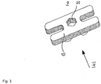
Fig 3 eine perspektivische Einzeldarstellung eines Halters; -
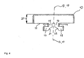
Fig. 4 eine ebene Ansicht des Halters entsprechend einer Blickrichtung IV derFig. 3 . - Mit 1 ist in den
Figuren 1 und2 ein Torpfosten bezeichnet, der als Hohlprofil mit ovalem Querschnitt ausgebildet ist und aus Metall oder Kunststoff bestehen kann. - Das Hohlprofil des Torpfostens weist einen Längsschlitz 2 auf, der mit einem auf der Innenseite des Hohlprofils angeformten Rechteckprofil 3 in durchgängiger Verbindung steht. Das Rechteckprofil 3 erstreckt sich symmetrisch beiderseits des Längsschlitzes 2 in Umfangsrichtung des Hohlprofils über den Längsschlitz hinaus. Das Gesamtsystem aus Längsschlitz 2 und Rechteckprofil 3 ist im Übrigen ausgehend von der Außenseite des Hohlprofils zur Innenseite hin um ein Maß 4 versetzt und es bilden die an den Längsschlitz 2 beidseitig angrenzenden Abschnitte 5, 6 des zur Innenseite hin versetzten Teils ebene Anlageflächen, deren Bedeutung im Folgenden noch erläutert werden wird. In ihrer Gesamtheit bilden die Abschnitte 5, 6 eine nutartige Ausnehmung 24 in der Umfangsfläche des Torpfostens 1.
- Das Rechteckprofil 3 bildet eine Aufnahme für die Randleine 7 eines Tornetzes 8, so dass die Breite des Längsschlitzes 2 dahingehend bemessen ist, dass beim Aufbau eines Tores die Randleine 7 in Querrichtung zu dem Längsschlitz 2 in diesen einführbar ist.
- Um die Randleine 7 in ihrer Montageposition zu sichern, sind mehrere Halter 9 vorgesehen und es wird hierzu ergänzend auf die
Figuren 3 und4 Bezug genommen. - Jeder Halter 9 besteht aus einem H-förmigen Grundkörper 10, an dessen Unterseite 11 zwei untereinander gleiche, sich symmetrisch bezüglich einer Mittelebene 12 erstreckende Haltewinkeln 13, 14 angeformt sind. Diese Mittelebene 12 erstreckt sich senkrecht zu der Längserstreckung des H-förmigen Grundkörpers 10. Ein jeder der beiden Haltewinkel 13, 14 besteht aus einem, sich senkrecht zu einer Grundebene des Grundkörpers 10 erstreckenden ersten Teil 15, 16 und einem sich an diesen ersten Teil anschließenden, sich parallel zu dieser erstreckenden zweiten Teil 17, 18.
- Die Länge und Dicke der ersten Teile 15, 16 sind dahingehend bemessen, dass ein Einsetzen des Halters 9 über den Längsschlitz 2 in das Rechteckprofil 3 und durch Drehen um dessen Hochachse 19 eine Überführung der zweiten Teile 17, 18 in eine solche Position möglich ist, in der diese die seitlichen Abschnitte 5, 6 innenseitig hintergreifen, hierbei Verbindung mit dem Grundkörper eine Fixierung der Halter 9 in dem Längsschlitz 2 bewirkend.
- Die Halter 9 können aus Metall oder auch einem Kunststoff bestehen.
- Die Dicke der Wandung des Torpfostens 1 ist in Abstimmung mit der Länge der ersten Teile 15, 16 dahingehend bemessen, dass sich ein Reibschluss zwischen dem Halter 9 und dem Torpfosten ergibt, der einen hinreichend sicheren Sitz des Halters 9 in seiner Einsetz- bzw. Montageposition bewirkt.
- Die Dicke 23 des Grundkörpers 10 ist mit der Maßgabe bemessen, dass dieser in der Montageposition in der Ausnehmung 24 versenkt angeordnet ist und insbesondere nicht außenseitig vorsteht.
- Die zweiten Teile 17, 18 weisen auf ihren, dem Grundkörper 10 abgekehrten Seiten Ausnehmungen 21, 22 auf, die sich zu einem angenäherten Halbkreisprofil komplettieren. In der Montageposition entsteht auf diese Weise eine Aufnahme für die Randleine 7.
- Die Endbereiche des H-förmigen Profils der Halter 9 bieten hinreichende Ansatzpunkte, um diese Halter manuell ohne die Notwendigkeit eines Werkzeugs zwischen einer Montageposition einerseits und einer Freigabeposition andererseits durch Drehen um deren Hochachse 19 zu überführen. Es besteht jedoch die Möglichkeit, über ein Innenprofil, hier ein Innensechskantprofil 20 die Drehung des Halters unter Verwendung eines Werkzeugs, hier eines Innensechskant-Schlüssels zu bewirken.
- In dem vorstehend beschriebenen Sinne können beide Torpfosten ausgestaltet sein. Gleiches gilt auch für den die Torpfosten horizontal verbindenden Querholm.
- Die Halter 9 werden in hinreichender Anzahl entlang der Torpfosten 1 sowie des Querholms positioniert, nachdem die Randleinen 7 in die jeweiligen Längsschlitze 2 eingesetzt worden sind. In der Montageposition bieten die Halter 9 eine zuverlässige Fixierung eines Tornetzes 8. Zur Demontage des Tornetzes 8 werden zunächst die Halter 9 in deren Freigabeposition überführt und anschließend den Längsschlitzen 2 entnommen. Anschließend kann auch das Tornetz 8 entfernt werden.
- Man erkennt, dass auf diese Weise eine besonders einfach zu handhabende Befestigungstechnik für ein Tornetz 8 dargestellt ist, zu deren Betätigung grundsätzlich kein Werkzeug erforderlich ist.
-
- 1. Torpfosten
- 2. Längsschlitz
- 3. Rechteckprofil
- 4. Maß
- 5. Abschnitt
- 6. Abschnitt
- 7. Randleine
- 8. Tornetz
- 9. Halter
- 10. Grundkörper
- 11. Unterseite
- 12. Mittelebene
- 13. Haltewinkel
- 14. Haltewinkel
- 15. erster Teil
- 16. erster Teil
- 17. zweiter Teil
- 18. zweiter Teil
- 19. Hochachse
- 20. Innensechskant
- 21. Ausnehmung
- 22. Ausnehmung
- 23. Dicke
- 24. Ausnehmung
Claims (6)
- Tor bestehend zumindest aus einer Rahmenkonstruktion, die lösbar mit einem Tornetz (8) in Verbindung steht, wobei das Tornetz (8) aus dessen Berandung bildenden Randleinen (7) und dem übrigen Netzkörper besteht, dadurch gekennzeichnet, dass die langgestreckten Elemente der Rahmenkonstruktion mit Längsschlitzen (2) versehen sind, die innenseitig bezüglich des jeweiligen Elementes mit einem Hohlprofil in Verbindung stehen, dass der Längsschlitz (2) seitlich durch Abschnitte (5, 6) begrenzt wird, dass zur Befestigung des Tornetzes (8) eine über den Längsschlitz (2) in das Hohlprofil eingesetzte Randleine (7) mittels mehreren Haltern (9) in der Einsetzposition fixiert ist, dass jeder Halter (9) über den Längsschlitz (2) in das Hohlprofil einsetzbar ist und zwischen einer Einsetzposition, in der er in dem Längsschlitz (2) fixiert ist und einer Entnahmeposition, in der er dem Längsschlitz (2) entnehmbar ist, bewegbar ist, dass der Halter (9) durch eine Drehbewegung um seine Hochachse (19) zwischen der Entnahmeposition und der Einsetzposition bewegbar ist und dass der Halter (9) mit einer profilierten, zum Einsetzen eines Werkzeugs zum Drehen um die Hochachse (19) bestimmten Ausnehmung versehen ist.
- Tor nach Anspruch 1, dadurch gekennzeichnet, dass jeder Halter (9) mit Haltewinkeln (13, 14) versehen ist, die in der Einsetzposition zur Fixierung des Halters (9) durch Hintergreifen der Abschnitte (5, 6) eingerichtet und an einem Grundkörper (10) des Halters (9) angeordnet sind.
- Tor nach Anspruch 1 oder 2, dadurch gekennzeichnet, dass in der Einsetzposition des Halters (9) die Abschnitte (5, 6) durch den Grundkörper (10) übergriffen sind.
- Tor nach einem der Ansprüche 1 bis 3, dadurch gekennzeichnet, dass die Abschnitte (5, 6) beiderseits eines Längsschlitzes (2) in einer außenseitigen Ausnehmung (24) eines Torpfostens (1) oder eines Querholmes als Teil der Rahmenkonstruktion angeordnet sind.
- Tor nach Anspruch 4, dadurch gekennzeichnet, dass die Ausnehmung (24) eine Tiefe aufweist, die größer als oder gleich der Dicke (23) des Grundkörpers (10) bemessen ist.
- Tor nach einem der Ansprüche 2 bis 5, dadurch gekennzeichnet, dass die Haltewinkel (13, 14) unterseitig Ausnehmungen (21, 22) aufweisen, die in der Einsetzposition des Halters (9) zur teilweisen Aufnahme der Randleine (7) bestimmt sind.
Priority Applications (1)
| Application Number | Priority Date | Filing Date | Title |
|---|---|---|---|
| PL19000392T PL3626317T3 (pl) | 2018-09-18 | 2019-09-03 | Bramka |
Applications Claiming Priority (1)
| Application Number | Priority Date | Filing Date | Title |
|---|---|---|---|
| DE202018004321.4U DE202018004321U1 (de) | 2018-09-18 | 2018-09-18 | Tor |
Publications (2)
| Publication Number | Publication Date |
|---|---|
| EP3626317A1 true EP3626317A1 (de) | 2020-03-25 |
| EP3626317B1 EP3626317B1 (de) | 2021-06-09 |
Family
ID=64457253
Family Applications (1)
| Application Number | Title | Priority Date | Filing Date |
|---|---|---|---|
| EP19000392.1A Active EP3626317B1 (de) | 2018-09-18 | 2019-09-03 | Tor |
Country Status (5)
| Country | Link |
|---|---|
| EP (1) | EP3626317B1 (de) |
| DE (1) | DE202018004321U1 (de) |
| DK (1) | DK3626317T3 (de) |
| ES (1) | ES2884795T3 (de) |
| PL (1) | PL3626317T3 (de) |
Families Citing this family (2)
| Publication number | Priority date | Publication date | Assignee | Title |
|---|---|---|---|---|
| US20220316231A1 (en) * | 2019-09-05 | 2022-10-06 | Indefatigable Holdings Pty Ltd | Mesh restraint |
| US12551768B1 (en) | 2025-07-06 | 2026-02-17 | Luca SALVATORE | Net capture recreational frame |
Citations (4)
| Publication number | Priority date | Publication date | Assignee | Title |
|---|---|---|---|---|
| DE3942607A1 (de) * | 1989-12-22 | 1991-06-27 | Joba Bausysteme Und Sportgerae | Verbindung von netzen fuer sportgeraete mit pfosten |
| JP2002325874A (ja) * | 2001-05-07 | 2002-11-12 | Rui-Taka:Kk | ネット取付装置 |
| US20060131812A1 (en) * | 2004-12-16 | 2006-06-22 | Kwik Goal Ltd. | Tamper resistant fastener for sports netting |
| DE202008000430U1 (de) * | 2008-01-11 | 2008-04-03 | Schäper Sportgerätebau GmbH | Netzpfosten mit Netzhaken |
-
2018
- 2018-09-18 DE DE202018004321.4U patent/DE202018004321U1/de not_active Expired - Lifetime
-
2019
- 2019-09-03 PL PL19000392T patent/PL3626317T3/pl unknown
- 2019-09-03 ES ES19000392T patent/ES2884795T3/es active Active
- 2019-09-03 DK DK19000392.1T patent/DK3626317T3/da active
- 2019-09-03 EP EP19000392.1A patent/EP3626317B1/de active Active
Patent Citations (4)
| Publication number | Priority date | Publication date | Assignee | Title |
|---|---|---|---|---|
| DE3942607A1 (de) * | 1989-12-22 | 1991-06-27 | Joba Bausysteme Und Sportgerae | Verbindung von netzen fuer sportgeraete mit pfosten |
| JP2002325874A (ja) * | 2001-05-07 | 2002-11-12 | Rui-Taka:Kk | ネット取付装置 |
| US20060131812A1 (en) * | 2004-12-16 | 2006-06-22 | Kwik Goal Ltd. | Tamper resistant fastener for sports netting |
| DE202008000430U1 (de) * | 2008-01-11 | 2008-04-03 | Schäper Sportgerätebau GmbH | Netzpfosten mit Netzhaken |
Also Published As
| Publication number | Publication date |
|---|---|
| DK3626317T3 (da) | 2021-08-23 |
| EP3626317B1 (de) | 2021-06-09 |
| ES2884795T3 (es) | 2021-12-13 |
| DE202018004321U1 (de) | 2018-11-09 |
| PL3626317T3 (pl) | 2021-12-06 |
Similar Documents
| Publication | Publication Date | Title |
|---|---|---|
| DE19533845B4 (de) | Gehäuseelement zum Halten und Schützen für Rohre, Kanalisation, elektrische Leitungen und andere längliche Gegenstände, insbesondere für Kraftfahrzeuge | |
| DE3205795C2 (de) | Vorrichtung zum Halten von Platinen mit gedruckten Schaltungen | |
| DE1654513B2 (de) | Verbindung zwischen Ständern und Querbalken eines Gestells | |
| DE19815047A1 (de) | Anordnung zur schraubenlosen Verbindung von Gitterkabelbahnen | |
| DE2506128A1 (de) | Windschutzscheibenwischanlage | |
| DE3726200A1 (de) | Aufsatzteil, insbesondere zum halten von ski, surfbrettern oder dergleichen, fuer eine traegerstange einer aussen an einem kraftfahrzeug anzubringenden traegerkonstruktion | |
| EP3626317A1 (de) | Tor | |
| DE1609490A1 (de) | Waende,Scheidewaende u.dgl.,mit geringer akustischer Leitfaehigkeit,und zu deren Aufbau verwendbare besondere Teile | |
| DE3108437C2 (de) | Vorrichtung zum Montieren von Einbaudosen für Elektroinstallation | |
| DE2400177B2 (de) | Vorrichtung zum lösbaren Zusammenhalten eines Skistockpaares | |
| DE19502681A1 (de) | Zugentlastungs- und Befestigungselement | |
| DE3929095A1 (de) | Energiefuehrungskette | |
| DE102016124988A1 (de) | Beschlag für das Verlegen von Terrassendielen | |
| DE29807973U1 (de) | Mehrteilige Begrenzungsmauer, insbesondere für Frühbeete, sowie Frühbeet | |
| DE910589C (de) | Anordnung zur Befestigung von Schutzgittern u. dgl. | |
| DE668656C (de) | Schuhabstreifmatte mit feststehenden Buersten | |
| DE19531658B4 (de) | Stützvorrichtung für eine Kabelbahn | |
| DE2710224A1 (de) | Vorrichtung zur positionierung von teilen, insbesondere von schalungselementen im betonbau | |
| DE19829962C2 (de) | Vorrichtung zum Glätten von Verputz | |
| DE2816952C2 (de) | Gelenkverbindung zur lösbaren Lagerung von Wendetafeln in Halteschienen | |
| DE60319315T2 (de) | Verriegelungselement für einen Gitterrost auf einer Entwässerungsrinne und Werkzeug zum Entfernen desselben | |
| DE19607761A1 (de) | Leiternschuh für Leitern beliebiger Art | |
| DE102017007072A1 (de) | Mörtelschlitten | |
| EP1266371A1 (de) | Vorrichtung zur halterung von wendetafeln oder dergleichen | |
| DE1429658C (de) | Vorrichtung zum Befestigen von Fachböden oder von Trägern für Fachböden od. dgl. an aufrechten Tragpfosten |
Legal Events
| Date | Code | Title | Description |
|---|---|---|---|
| PUAI | Public reference made under article 153(3) epc to a published international application that has entered the european phase |
Free format text: ORIGINAL CODE: 0009012 |
|
| STAA | Information on the status of an ep patent application or granted ep patent |
Free format text: STATUS: THE APPLICATION HAS BEEN PUBLISHED |
|
| AK | Designated contracting states |
Kind code of ref document: A1 Designated state(s): AL AT BE BG CH CY CZ DE DK EE ES FI FR GB GR HR HU IE IS IT LI LT LU LV MC MK MT NL NO PL PT RO RS SE SI SK SM TR |
|
| AX | Request for extension of the european patent |
Extension state: BA ME |
|
| STAA | Information on the status of an ep patent application or granted ep patent |
Free format text: STATUS: REQUEST FOR EXAMINATION WAS MADE |
|
| 17P | Request for examination filed |
Effective date: 20200824 |
|
| RBV | Designated contracting states (corrected) |
Designated state(s): AL AT BE BG CH CY CZ DE DK EE ES FI FR GB GR HR HU IE IS IT LI LT LU LV MC MK MT NL NO PL PT RO RS SE SI SK SM TR |
|
| GRAP | Despatch of communication of intention to grant a patent |
Free format text: ORIGINAL CODE: EPIDOSNIGR1 |
|
| STAA | Information on the status of an ep patent application or granted ep patent |
Free format text: STATUS: GRANT OF PATENT IS INTENDED |
|
| INTG | Intention to grant announced |
Effective date: 20210219 |
|
| RIN1 | Information on inventor provided before grant (corrected) |
Inventor name: LAWES, STEFFAN |
|
| GRAS | Grant fee paid |
Free format text: ORIGINAL CODE: EPIDOSNIGR3 |
|
| GRAA | (expected) grant |
Free format text: ORIGINAL CODE: 0009210 |
|
| STAA | Information on the status of an ep patent application or granted ep patent |
Free format text: STATUS: THE PATENT HAS BEEN GRANTED |
|
| AK | Designated contracting states |
Kind code of ref document: B1 Designated state(s): AL AT BE BG CH CY CZ DE DK EE ES FI FR GB GR HR HU IE IS IT LI LT LU LV MC MK MT NL NO PL PT RO RS SE SI SK SM TR |
|
| REG | Reference to a national code |
Ref country code: GB Ref legal event code: FG4D Free format text: NOT ENGLISH |
|
| REG | Reference to a national code |
Ref country code: CH Ref legal event code: EP Ref country code: AT Ref legal event code: REF Ref document number: 1399983 Country of ref document: AT Kind code of ref document: T Effective date: 20210615 |
|
| REG | Reference to a national code |
Ref country code: DE Ref legal event code: R096 Ref document number: 502019001547 Country of ref document: DE |
|
| REG | Reference to a national code |
Ref country code: IE Ref legal event code: FG4D Free format text: LANGUAGE OF EP DOCUMENT: GERMAN |
|
| REG | Reference to a national code |
Ref country code: DK Ref legal event code: T3 Effective date: 20210820 |
|
| REG | Reference to a national code |
Ref country code: SE Ref legal event code: TRGR |
|
| REG | Reference to a national code |
Ref country code: LT Ref legal event code: MG9D |
|
| PG25 | Lapsed in a contracting state [announced via postgrant information from national office to epo] |
Ref country code: BG Free format text: LAPSE BECAUSE OF FAILURE TO SUBMIT A TRANSLATION OF THE DESCRIPTION OR TO PAY THE FEE WITHIN THE PRESCRIBED TIME-LIMIT Effective date: 20210909 Ref country code: LT Free format text: LAPSE BECAUSE OF FAILURE TO SUBMIT A TRANSLATION OF THE DESCRIPTION OR TO PAY THE FEE WITHIN THE PRESCRIBED TIME-LIMIT Effective date: 20210609 Ref country code: HR Free format text: LAPSE BECAUSE OF FAILURE TO SUBMIT A TRANSLATION OF THE DESCRIPTION OR TO PAY THE FEE WITHIN THE PRESCRIBED TIME-LIMIT Effective date: 20210609 Ref country code: FI Free format text: LAPSE BECAUSE OF FAILURE TO SUBMIT A TRANSLATION OF THE DESCRIPTION OR TO PAY THE FEE WITHIN THE PRESCRIBED TIME-LIMIT Effective date: 20210609 |
|
| REG | Reference to a national code |
Ref country code: NL Ref legal event code: MP Effective date: 20210609 |
|
| PG25 | Lapsed in a contracting state [announced via postgrant information from national office to epo] |
Ref country code: LV Free format text: LAPSE BECAUSE OF FAILURE TO SUBMIT A TRANSLATION OF THE DESCRIPTION OR TO PAY THE FEE WITHIN THE PRESCRIBED TIME-LIMIT Effective date: 20210609 Ref country code: NO Free format text: LAPSE BECAUSE OF FAILURE TO SUBMIT A TRANSLATION OF THE DESCRIPTION OR TO PAY THE FEE WITHIN THE PRESCRIBED TIME-LIMIT Effective date: 20210909 Ref country code: RS Free format text: LAPSE BECAUSE OF FAILURE TO SUBMIT A TRANSLATION OF THE DESCRIPTION OR TO PAY THE FEE WITHIN THE PRESCRIBED TIME-LIMIT Effective date: 20210609 Ref country code: GR Free format text: LAPSE BECAUSE OF FAILURE TO SUBMIT A TRANSLATION OF THE DESCRIPTION OR TO PAY THE FEE WITHIN THE PRESCRIBED TIME-LIMIT Effective date: 20210910 |
|
| REG | Reference to a national code |
Ref country code: ES Ref legal event code: FG2A Ref document number: 2884795 Country of ref document: ES Kind code of ref document: T3 Effective date: 20211213 |
|
| PG25 | Lapsed in a contracting state [announced via postgrant information from national office to epo] |
Ref country code: SK Free format text: LAPSE BECAUSE OF FAILURE TO SUBMIT A TRANSLATION OF THE DESCRIPTION OR TO PAY THE FEE WITHIN THE PRESCRIBED TIME-LIMIT Effective date: 20210609 Ref country code: EE Free format text: LAPSE BECAUSE OF FAILURE TO SUBMIT A TRANSLATION OF THE DESCRIPTION OR TO PAY THE FEE WITHIN THE PRESCRIBED TIME-LIMIT Effective date: 20210609 Ref country code: NL Free format text: LAPSE BECAUSE OF FAILURE TO SUBMIT A TRANSLATION OF THE DESCRIPTION OR TO PAY THE FEE WITHIN THE PRESCRIBED TIME-LIMIT Effective date: 20210609 Ref country code: RO Free format text: LAPSE BECAUSE OF FAILURE TO SUBMIT A TRANSLATION OF THE DESCRIPTION OR TO PAY THE FEE WITHIN THE PRESCRIBED TIME-LIMIT Effective date: 20210609 Ref country code: PT Free format text: LAPSE BECAUSE OF FAILURE TO SUBMIT A TRANSLATION OF THE DESCRIPTION OR TO PAY THE FEE WITHIN THE PRESCRIBED TIME-LIMIT Effective date: 20211011 Ref country code: SM Free format text: LAPSE BECAUSE OF FAILURE TO SUBMIT A TRANSLATION OF THE DESCRIPTION OR TO PAY THE FEE WITHIN THE PRESCRIBED TIME-LIMIT Effective date: 20210609 |
|
| REG | Reference to a national code |
Ref country code: DE Ref legal event code: R097 Ref document number: 502019001547 Country of ref document: DE |
|
| PLBE | No opposition filed within time limit |
Free format text: ORIGINAL CODE: 0009261 |
|
| STAA | Information on the status of an ep patent application or granted ep patent |
Free format text: STATUS: NO OPPOSITION FILED WITHIN TIME LIMIT |
|
| 26N | No opposition filed |
Effective date: 20220310 |
|
| REG | Reference to a national code |
Ref country code: BE Ref legal event code: MM Effective date: 20210930 |
|
| PG25 | Lapsed in a contracting state [announced via postgrant information from national office to epo] |
Ref country code: MC Free format text: LAPSE BECAUSE OF FAILURE TO SUBMIT A TRANSLATION OF THE DESCRIPTION OR TO PAY THE FEE WITHIN THE PRESCRIBED TIME-LIMIT Effective date: 20210609 Ref country code: AL Free format text: LAPSE BECAUSE OF FAILURE TO SUBMIT A TRANSLATION OF THE DESCRIPTION OR TO PAY THE FEE WITHIN THE PRESCRIBED TIME-LIMIT Effective date: 20210609 |
|
| PG25 | Lapsed in a contracting state [announced via postgrant information from national office to epo] |
Ref country code: LU Free format text: LAPSE BECAUSE OF NON-PAYMENT OF DUE FEES Effective date: 20210903 Ref country code: IE Free format text: LAPSE BECAUSE OF NON-PAYMENT OF DUE FEES Effective date: 20210903 Ref country code: BE Free format text: LAPSE BECAUSE OF NON-PAYMENT OF DUE FEES Effective date: 20210930 |
|
| PG25 | Lapsed in a contracting state [announced via postgrant information from national office to epo] |
Ref country code: CY Free format text: LAPSE BECAUSE OF FAILURE TO SUBMIT A TRANSLATION OF THE DESCRIPTION OR TO PAY THE FEE WITHIN THE PRESCRIBED TIME-LIMIT Effective date: 20210609 |
|
| PG25 | Lapsed in a contracting state [announced via postgrant information from national office to epo] |
Ref country code: HU Free format text: LAPSE BECAUSE OF FAILURE TO SUBMIT A TRANSLATION OF THE DESCRIPTION OR TO PAY THE FEE WITHIN THE PRESCRIBED TIME-LIMIT; INVALID AB INITIO Effective date: 20190903 |
|
| PG25 | Lapsed in a contracting state [announced via postgrant information from national office to epo] |
Ref country code: MK Free format text: LAPSE BECAUSE OF FAILURE TO SUBMIT A TRANSLATION OF THE DESCRIPTION OR TO PAY THE FEE WITHIN THE PRESCRIBED TIME-LIMIT Effective date: 20210609 |
|
| PG25 | Lapsed in a contracting state [announced via postgrant information from national office to epo] |
Ref country code: MT Free format text: LAPSE BECAUSE OF FAILURE TO SUBMIT A TRANSLATION OF THE DESCRIPTION OR TO PAY THE FEE WITHIN THE PRESCRIBED TIME-LIMIT Effective date: 20210609 |
|
| PGFP | Annual fee paid to national office [announced via postgrant information from national office to epo] |
Ref country code: DE Payment date: 20250929 Year of fee payment: 7 Ref country code: DK Payment date: 20250929 Year of fee payment: 7 |
|
| PGFP | Annual fee paid to national office [announced via postgrant information from national office to epo] |
Ref country code: PL Payment date: 20250827 Year of fee payment: 7 Ref country code: IT Payment date: 20250924 Year of fee payment: 7 |
|
| REG | Reference to a national code |
Ref country code: CH Ref legal event code: U11 Free format text: ST27 STATUS EVENT CODE: U-0-0-U10-U11 (AS PROVIDED BY THE NATIONAL OFFICE) Effective date: 20251016 |
|
| PGFP | Annual fee paid to national office [announced via postgrant information from national office to epo] |
Ref country code: FR Payment date: 20250922 Year of fee payment: 7 Ref country code: AT Payment date: 20250524 Year of fee payment: 7 |
|
| PGFP | Annual fee paid to national office [announced via postgrant information from national office to epo] |
Ref country code: SE Payment date: 20250929 Year of fee payment: 7 |
|
| PGFP | Annual fee paid to national office [announced via postgrant information from national office to epo] |
Ref country code: CZ Payment date: 20250827 Year of fee payment: 7 |
|
| PG25 | Lapsed in a contracting state [announced via postgrant information from national office to epo] |
Ref country code: TR Free format text: LAPSE BECAUSE OF FAILURE TO SUBMIT A TRANSLATION OF THE DESCRIPTION OR TO PAY THE FEE WITHIN THE PRESCRIBED TIME-LIMIT Effective date: 20210609 |
|
| PGFP | Annual fee paid to national office [announced via postgrant information from national office to epo] |
Ref country code: GB Payment date: 20251024 Year of fee payment: 7 |
|
| PGFP | Annual fee paid to national office [announced via postgrant information from national office to epo] |
Ref country code: CH Payment date: 20251016 Year of fee payment: 7 |
|
| PGFP | Annual fee paid to national office [announced via postgrant information from national office to epo] |
Ref country code: ES Payment date: 20251020 Year of fee payment: 7 |