EP3626317B1 - But - Google Patents
But Download PDFInfo
- Publication number
- EP3626317B1 EP3626317B1 EP19000392.1A EP19000392A EP3626317B1 EP 3626317 B1 EP3626317 B1 EP 3626317B1 EP 19000392 A EP19000392 A EP 19000392A EP 3626317 B1 EP3626317 B1 EP 3626317B1
- Authority
- EP
- European Patent Office
- Prior art keywords
- holder
- goal
- longitudinal slot
- sections
- net
- Prior art date
- Legal status (The legal status is an assumption and is not a legal conclusion. Google has not performed a legal analysis and makes no representation as to the accuracy of the status listed.)
- Active
Links
Images


Classifications
-
- A—HUMAN NECESSITIES
- A63—SPORTS; GAMES; AMUSEMENTS
- A63B—APPARATUS FOR PHYSICAL TRAINING, GYMNASTICS, SWIMMING, CLIMBING, OR FENCING; BALL GAMES; TRAINING EQUIPMENT
- A63B63/00—Targets or goals for ball games
- A63B63/004—Goals of the type used for football, handball, hockey or the like
-
- A—HUMAN NECESSITIES
- A63—SPORTS; GAMES; AMUSEMENTS
- A63B—APPARATUS FOR PHYSICAL TRAINING, GYMNASTICS, SWIMMING, CLIMBING, OR FENCING; BALL GAMES; TRAINING EQUIPMENT
- A63B63/00—Targets or goals for ball games
- A63B63/004—Goals of the type used for football, handball, hockey or the like
- A63B2063/005—Goals of the type used for football, handball, hockey or the like having means not protruding from the profile of the post for attachment of a net
-
- A—HUMAN NECESSITIES
- A63—SPORTS; GAMES; AMUSEMENTS
- A63B—APPARATUS FOR PHYSICAL TRAINING, GYMNASTICS, SWIMMING, CLIMBING, OR FENCING; BALL GAMES; TRAINING EQUIPMENT
- A63B2210/00—Space saving
- A63B2210/50—Size reducing arrangements for stowing or transport
Definitions
- the invention relates to a door according to the preamble of claim 1.
- Such goals are for use in various sports such. B. football, handball, etc. and can be set up for a time-limited or unlimited use. They essentially consist of a frame structure to be fixed at the bottom, which is generally formed by two lateral goal posts that are connected to one another at the top via a crossbar. A goal net is attached to this frame structure, which is usually a detachable attachment. For this purpose, different fastening techniques are available, the handling of which in terms of assembly is more or less complex, in particular regularly necessitating the use of a tool.
- the frame structure of which consists, among other things, of two vertically extending goal posts, which are connected to each other on the top side via a cross bar.
- the goal posts and the transverse spar are provided with channels running in their longitudinal extension, which are designed to accommodate holders that can be used transversely to the longitudinal extension of the channel and, in the inserted state, between an open position, which can be inserted into and removed from them Allows channels and a closed position in which there is a frictional fixation in these channels, about an axis extending perpendicular to these channels can be rotated.
- the channels are provided with inwardly extending webs, leaving a central slot, the outer sides of which lie in a common plane with the adjoining walls of the goal posts and the transverse spar.
- the holders thus form structures that protrude on the outside from the goal post and the cross bar.
- the lower area of the channels, viewed from the webs, is used Receipt of an edge line of the goal net, which is secured in this way and arranged at a distance from the holders.
- An outside protrusion of parts of the holder can be perceived as a nuisance in individual cases, the type of reception of the edge line leading to comparatively large dimensions of the channels.
- a comparable frame construction of a gate is from the DE 39 42 607 A1 known. This is characterized by a head part which is formed in one piece with a fastening part and is positively locked in a groove extending in the longitudinal direction of a goal post, which is secured against being pulled out, the fastening part being provided with a recess which is open to the outside and intended to receive and clamp the edge line of a goal net.
- the outer contour of the fastening part essentially fits into the contour of the outside of the goal post, the division into a fastening part and a head part results in a comparatively complicated embodiment of the elements intended for fastening a goal net, which takes up a considerable amount of space.
- Another frame construction for a gate is from the DE 20 2008 000 430 U1 known, are provided in the holder, for example, for the edge line of a goal net, which can be used in longitudinal grooves of the goal posts or comparable elements.
- Each holder is provided with a securing element which is captively connected to the former and is intended for opening or closing a receiving space for the edge line. Accordingly, the securing element can be pivoted between an open position and a closed position about an axis relative to the holder on the latter.
- the holder is secured in the longitudinal groove by means of webs formed on both sides which are in engagement with assembly grooves.
- this embodiment leads to a relatively complicated embodiment which takes up a considerable amount of space.
- the object of the invention is to design a goal on which a goal net can be mounted and dismantled with the least possible effort, with only a small structural volume being required to partially accommodate an edge line of the goal net. This object is achieved in such a door by the features of the characterizing part of claim 1.
- the frame structure namely its elongated elements, are provided with longitudinal slots in which the boundaries of the goal net, in particular its edge ropes, are received and secured in place by means of holders.
- the goal posts and a cross bar connecting them are considered elongated elements in this sense.
- an edge line is any type of edge of a goal net, which can be technically represented by rigid but also by flexible functional elements.
- the longitudinal slots are molded into the outside of the respective element and are connected to a hollow profile which is located inside the element, the longitudinal slots being laterally bounded by sections that are attached to the holders to represent a fixation for the edge line located within the hollow structure cooperate.
- the holders as such can also be designed as components that are independent of the frame construction and, in this respect, only interact with the sections on the side of the longitudinal slot.
- functional elements that are permanently connected to the frame structure and are suitable and designed for performing a fixing function can also be considered as holders.
- the holders as such cannot be permanently connected to the frame structure either and can only be inserted into the longitudinal slots to represent a fixing function. They can be moved in these longitudinal slots between an insertion position, on the one hand, in which they act to fix the edge line, and a removal position, in which they can be removed from the longitudinal slots. In the inserted position, however, they cannot be removed from the respective longitudinal slot.
- Each holder can be moved between an insertion position on the one hand and a removal position on the other hand by rotating about its vertical axis.
- the vertical axis can extend perpendicular to the longitudinal slot.
- the base body can practically be formed by a flat structure which is advantageously designed with the proviso that it can be easily grasped manually in order to be able to rotate the individual holder between the insertion position and the removal position.
- the holders can be rotated between the two positions mentioned without the need for a tool. They are only additionally provided with a profiled recess, e.g. B. equipped in the manner of a hexagon socket or the like in order to be able to effect the rotation by means of a tool adapted to this profile.
- a profiled recess e.g. B. equipped in the manner of a hexagon socket or the like in order to be able to effect the rotation by means of a tool adapted to this profile.
- Each holder consists of a base body on which mounting brackets are formed, which, when a fixation is shown, are intended to interact with the sections mentioned on both sides of the longitudinal slot. Is in the insertion position. thus a clamping effect can be represented.
- Each holder can be moved between an insertion position on the one hand and a removal position on the other hand by rotating about its vertical axis.
- the vertical axis can extend perpendicular to the longitudinal slot.
- the base body can practically be formed by a flat structure which is advantageously designed with the proviso that it can be easily grasped manually in order to be able to rotate the individual holder between the insertion position and the removal position.
- the longitudinal slots are located within recesses of goal posts and / or crossbars of a frame structure forming a goal, the aforementioned sections forming the base of these recesses.
- the thickness of the base body of the holder is dimensioned with the stipulation that in the inserted position they in any case do not form any structures protruding on the outside from the crossbar or the goal post.
- the mounting brackets formed on the base bodies of the holders have recesses on the underside, that is, on their sides facing away from the base body, which in the insertion position complete to form a semicircular profile in which an edge line is at least partially accommodated in an unconstrained manner. At this point, however, are Depending on the cross-sectional shape of the edge line, other recess profiles are also possible, which are intended to partially accommodate an edge line.
- the goal according to the invention allows a simple assembly and disassembly of a goal net that is possible in principle without the need for a tool.
- This fastening technique can be used for both fixed and temporarily erected goals in all sports.
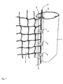
- a goal post which is designed as a hollow profile with an oval cross-section and can be made of metal or plastic.
- the hollow profile of the goal post has a longitudinal slot 2 which is in continuous connection with a rectangular profile 3 formed on the inside of the hollow profile.
- the rectangular profile 3 extends symmetrically on both sides of the longitudinal slot 2 in the circumferential direction of the hollow profile beyond the longitudinal slot.
- the overall system of longitudinal slot 2 and rectangular profile 3 is also offset by a measure 4 from the outside of the hollow profile to the inside, and the sections 5, 6 of the part offset towards the inside, which are adjacent to the longitudinal slot 2 on both sides, form flat contact surfaces will be explained below.
- the sections 5, 6 form a groove-like recess 24 in the peripheral surface of the goal post 1.
- the rectangular profile 3 forms a receptacle for the edge line 7 of a goal net 8, so that the width of the longitudinal slot 2 is dimensioned such that when a goal is set up, the edge line 7 can be inserted into the longitudinal slot 2 in the transverse direction.
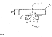
- Each holder 9 consists of an H-shaped base body 10, on the underside 11 of which two mounting brackets 13, 14, which are identical to one another and extend symmetrically with respect to a central plane 12, are formed.
- This central plane 12 extends perpendicular to the longitudinal extension of the H-shaped base body 10.
- Each of the two brackets 13, 14 consists of a first part 15, 16 extending perpendicular to a base plane of the base body 10 and a first part adjoining this first part , extending parallel to this second, part 17, 18.
- the lengths and thicknesses of the first parts 15, 16 are dimensioned in such a way that the holder 9 can be inserted into the rectangular profile 3 via the longitudinal slot 2 and the second parts 17, 18 can be transferred into such a position by rotating about its vertical axis 19, in which they engage behind the lateral sections 5, 6 on the inside, in this connection with the base body causing the holder 9 to be fixed in the longitudinal slot 2.
- the holder 9 can be made of metal or a plastic.
- the thickness of the wall of the goal post 1 is dimensioned in coordination with the length of the first parts 15, 16 in such a way that there is a frictional connection between the holder 9 and the goal post, which ensures a sufficiently secure fit of the holder 9 in its insertion or assembly position causes.
- the thickness 23 of the base body 10 is dimensioned with the proviso that it is arranged sunk in the recess 24 in the assembly position and in particular does not protrude on the outside.
- the second parts 17, 18 have recesses 21, 22 on their sides facing away from the base body 10, which are completed to form an approximately semicircular profile. In this way, a receptacle for the edge line 7 is created in the assembly position.
- the end regions of the H-shaped profile of the holder 9 offer sufficient starting points to these holders manually without the need for a tool between an assembly position on the one hand and a release position on the other hand by turning around To transfer vertical axis 19.
- an inner profile here a hexagon socket profile 20
- a tool here a hexagon socket wrench
- goal posts can be designed in the sense described above. The same also applies to the cross bar horizontally connecting the goal posts.
- the holders 9 are positioned in sufficient numbers along the goal posts 1 and the transverse spar after the edge lines 7 have been inserted into the respective longitudinal slots 2. In the assembly position, the holders 9 provide a reliable fixation of a goal net 8. To dismantle the goal net 8, the holders 9 are first transferred to their release position and then removed from the longitudinal slots 2. The goal net 8 can then also be removed.
Landscapes
- Health & Medical Sciences (AREA)
- General Health & Medical Sciences (AREA)
- Physical Education & Sports Medicine (AREA)
- Gates (AREA)
- Mutual Connection Of Rods And Tubes (AREA)
Claims (3)
- But constitué d'au moins une structure de cadre, qui est reliée de manière amovible à un filet de but (8), dans lequel le filet de but (8) est constitué de cordelettes de bord (7) formant son encadrement et du corps de filet restant, dans lequel les éléments étirés en longueur de la structure de cadre sont pourvus d'entailles longitudinales (2), qui sont reliées côté intérieur par rapport à l'élément respectif à un profil creux, dans lequel l'entaille longitudinale (2) est délimitée latéralement par des sections (5, 6), dans lequel une cordelette de bord (7) insérée dans le profil creux par l'intermédiaire de l'entaille longitudinale (2) est bloquée au moyen de plusieurs dispositifs de maintien (9) dans la position d'insertion pour fixer le filet de but (8), dans lequel chaque dispositif de maintien (9) peut être inséré dans le profil creux par l'intermédiaire de l'entaille longitudinale (2) et peut être déplacé entre une position d'insertion, dans laquelle il est bloqué dans l'entaille longitudinale (2), et une position de retrait, dans laquelle il peut être retiré de l'entaille longitudinale (2), dans lequel le dispositif de maintien (9) peut être déplacé par un déplacement de rotation autour de son axe vertical (19) entre la position de retrait et la position d'insertion, dans lequel chaque dispositif de maintien (9) est pourvu d'angles de maintien (13, 14), qui sont mis au point, dans la position d'insertion, pour bloquer le dispositif de maintien (9) en venant en prise par l'arrière avec les sections (5, 6) et sont disposés sur un corps de base (10) du dispositif de maintien (9), dans lequel chaque dispositif de maintien (9) est pourvu d'un évidement profilé destiné à insérer un outil destiné à tourner autour de l'axe vertical (19), et dans lequel
les sections (5, 6) sont disposées de part et d'autre d'une entaille longitudinale (2) dans un évidement (24) côté extérieur d'un poteau de but (1) ou d'un longeron transversal en tant que partie de la structure de cadre, caractérisé en ce que les angles de maintien (13, 14) présentent côté inférieur des évidements (21, 22) qui se destinent dans la position d'insertion du dispositif de maintien (9) à loger en partie la cordelette de bord (7). - But selon la revendication 1, caractérisé en ce que dans la position d'insertion du dispositif de maintien (9), les sections (5, 6) sont recouvertes par le corps de base (10).
- But selon la revendication 1 ou 2, caractérisé en ce que l'évidement (24) présente une profondeur qui présente une dimension supérieure à ou égale à l'épaisseur (23) du corps de base (10).
Priority Applications (1)
| Application Number | Priority Date | Filing Date | Title |
|---|---|---|---|
| PL19000392T PL3626317T3 (pl) | 2018-09-18 | 2019-09-03 | Bramka |
Applications Claiming Priority (1)
| Application Number | Priority Date | Filing Date | Title |
|---|---|---|---|
| DE202018004321.4U DE202018004321U1 (de) | 2018-09-18 | 2018-09-18 | Tor |
Publications (2)
| Publication Number | Publication Date |
|---|---|
| EP3626317A1 EP3626317A1 (fr) | 2020-03-25 |
| EP3626317B1 true EP3626317B1 (fr) | 2021-06-09 |
Family
ID=64457253
Family Applications (1)
| Application Number | Title | Priority Date | Filing Date |
|---|---|---|---|
| EP19000392.1A Active EP3626317B1 (fr) | 2018-09-18 | 2019-09-03 | But |
Country Status (5)
| Country | Link |
|---|---|
| EP (1) | EP3626317B1 (fr) |
| DE (1) | DE202018004321U1 (fr) |
| DK (1) | DK3626317T3 (fr) |
| ES (1) | ES2884795T3 (fr) |
| PL (1) | PL3626317T3 (fr) |
Cited By (1)
| Publication number | Priority date | Publication date | Assignee | Title |
|---|---|---|---|---|
| US12551768B1 (en) | 2025-07-06 | 2026-02-17 | Luca SALVATORE | Net capture recreational frame |
Families Citing this family (1)
| Publication number | Priority date | Publication date | Assignee | Title |
|---|---|---|---|---|
| WO2021042157A1 (fr) * | 2019-09-05 | 2021-03-11 | Indefatigable Holdings Pty Ltd | Dispositif de retenue de maille |
Family Cites Families (4)
| Publication number | Priority date | Publication date | Assignee | Title |
|---|---|---|---|---|
| DE3942607A1 (de) * | 1989-12-22 | 1991-06-27 | Joba Bausysteme Und Sportgerae | Verbindung von netzen fuer sportgeraete mit pfosten |
| JP2002325874A (ja) * | 2001-05-07 | 2002-11-12 | Rui-Taka:Kk | ネット取付装置 |
| US7241235B2 (en) * | 2004-12-16 | 2007-07-10 | Kwik Goal Ltd | Tamper resistant fastener for sports netting |
| DE202008000430U1 (de) * | 2008-01-11 | 2008-04-03 | Schäper Sportgerätebau GmbH | Netzpfosten mit Netzhaken |
-
2018
- 2018-09-18 DE DE202018004321.4U patent/DE202018004321U1/de not_active Expired - Lifetime
-
2019
- 2019-09-03 EP EP19000392.1A patent/EP3626317B1/fr active Active
- 2019-09-03 DK DK19000392.1T patent/DK3626317T3/da active
- 2019-09-03 PL PL19000392T patent/PL3626317T3/pl unknown
- 2019-09-03 ES ES19000392T patent/ES2884795T3/es active Active
Cited By (1)
| Publication number | Priority date | Publication date | Assignee | Title |
|---|---|---|---|---|
| US12551768B1 (en) | 2025-07-06 | 2026-02-17 | Luca SALVATORE | Net capture recreational frame |
Also Published As
| Publication number | Publication date |
|---|---|
| EP3626317A1 (fr) | 2020-03-25 |
| ES2884795T3 (es) | 2021-12-13 |
| DE202018004321U1 (de) | 2018-11-09 |
| DK3626317T3 (da) | 2021-08-23 |
| PL3626317T3 (pl) | 2021-12-06 |
Similar Documents
| Publication | Publication Date | Title |
|---|---|---|
| DE19533845B4 (de) | Gehäuseelement zum Halten und Schützen für Rohre, Kanalisation, elektrische Leitungen und andere längliche Gegenstände, insbesondere für Kraftfahrzeuge | |
| AT509796B1 (de) | Hohlprofil | |
| DE202013101519U1 (de) | Duschtür-Baugruppe | |
| DE2502453C3 (de) | Aus Aluminium gefertigter Gliederradiator für Zentralheizungsanlagen | |
| EP3626317A1 (fr) | But | |
| DE2237490B2 (de) | Zerlegbares Baugerüst | |
| DE4029694A1 (de) | Griff fuer eine kraftfahrzeugtuer | |
| DE19502681A1 (de) | Zugentlastungs- und Befestigungselement | |
| DE19719013C2 (de) | Mit einem Wandhalter versehenes, im Querschnitt U-förmiges Halteprofil für eine Trennwand | |
| DE2261822C3 (de) | Lüftungsvorrichtung | |
| DE2535811B2 (de) | Laufrollenbaugruppe fur den Flügel eines Schiebefensters o.dgl | |
| DE202011000065U1 (de) | Vorrichtung zum Aufhängen einer Gardine oder dergleichen | |
| DE3104309C1 (de) | Loesbare Halterung fuer Dachwindabweiser | |
| DE102004005781A1 (de) | Jalousieeinheit | |
| DE19829962C2 (de) | Vorrichtung zum Glätten von Verputz | |
| DE20318020U1 (de) | Werkstattwagen | |
| DE102016111091B3 (de) | Halterung für das Kennzeichen eines Fahrzeugs | |
| DE2810981C2 (de) | Vorrichtung zur Befestigung einer Zarge | |
| DE2363298A1 (de) | Auf- und abrollbarer vorhang | |
| DE102006001157B4 (de) | Gleiter für Paneelprofil | |
| DE1154245B (de) | Halter zum Befestigen von Tragschienen fuer Gardinen, Vorhaenge u. dgl. | |
| DE3303999A1 (de) | Schraube | |
| DE102007009667A1 (de) | Profilkonstruktion | |
| EP3243413B1 (fr) | Dispositif de support de pièces décoratives pour des rebords de fenêtres | |
| DE1061205B (de) | Verbindung der Druckverteilungsbuegel von Scheibenwischern |
Legal Events
| Date | Code | Title | Description |
|---|---|---|---|
| PUAI | Public reference made under article 153(3) epc to a published international application that has entered the european phase |
Free format text: ORIGINAL CODE: 0009012 |
|
| STAA | Information on the status of an ep patent application or granted ep patent |
Free format text: STATUS: THE APPLICATION HAS BEEN PUBLISHED |
|
| AK | Designated contracting states |
Kind code of ref document: A1 Designated state(s): AL AT BE BG CH CY CZ DE DK EE ES FI FR GB GR HR HU IE IS IT LI LT LU LV MC MK MT NL NO PL PT RO RS SE SI SK SM TR |
|
| AX | Request for extension of the european patent |
Extension state: BA ME |
|
| STAA | Information on the status of an ep patent application or granted ep patent |
Free format text: STATUS: REQUEST FOR EXAMINATION WAS MADE |
|
| 17P | Request for examination filed |
Effective date: 20200824 |
|
| RBV | Designated contracting states (corrected) |
Designated state(s): AL AT BE BG CH CY CZ DE DK EE ES FI FR GB GR HR HU IE IS IT LI LT LU LV MC MK MT NL NO PL PT RO RS SE SI SK SM TR |
|
| GRAP | Despatch of communication of intention to grant a patent |
Free format text: ORIGINAL CODE: EPIDOSNIGR1 |
|
| STAA | Information on the status of an ep patent application or granted ep patent |
Free format text: STATUS: GRANT OF PATENT IS INTENDED |
|
| INTG | Intention to grant announced |
Effective date: 20210219 |
|
| RIN1 | Information on inventor provided before grant (corrected) |
Inventor name: LAWES, STEFFAN |
|
| GRAS | Grant fee paid |
Free format text: ORIGINAL CODE: EPIDOSNIGR3 |
|
| GRAA | (expected) grant |
Free format text: ORIGINAL CODE: 0009210 |
|
| STAA | Information on the status of an ep patent application or granted ep patent |
Free format text: STATUS: THE PATENT HAS BEEN GRANTED |
|
| AK | Designated contracting states |
Kind code of ref document: B1 Designated state(s): AL AT BE BG CH CY CZ DE DK EE ES FI FR GB GR HR HU IE IS IT LI LT LU LV MC MK MT NL NO PL PT RO RS SE SI SK SM TR |
|
| REG | Reference to a national code |
Ref country code: GB Ref legal event code: FG4D Free format text: NOT ENGLISH |
|
| REG | Reference to a national code |
Ref country code: CH Ref legal event code: EP Ref country code: AT Ref legal event code: REF Ref document number: 1399983 Country of ref document: AT Kind code of ref document: T Effective date: 20210615 |
|
| REG | Reference to a national code |
Ref country code: DE Ref legal event code: R096 Ref document number: 502019001547 Country of ref document: DE |
|
| REG | Reference to a national code |
Ref country code: IE Ref legal event code: FG4D Free format text: LANGUAGE OF EP DOCUMENT: GERMAN |
|
| REG | Reference to a national code |
Ref country code: DK Ref legal event code: T3 Effective date: 20210820 |
|
| REG | Reference to a national code |
Ref country code: SE Ref legal event code: TRGR |
|
| REG | Reference to a national code |
Ref country code: LT Ref legal event code: MG9D |
|
| PG25 | Lapsed in a contracting state [announced via postgrant information from national office to epo] |
Ref country code: BG Free format text: LAPSE BECAUSE OF FAILURE TO SUBMIT A TRANSLATION OF THE DESCRIPTION OR TO PAY THE FEE WITHIN THE PRESCRIBED TIME-LIMIT Effective date: 20210909 Ref country code: LT Free format text: LAPSE BECAUSE OF FAILURE TO SUBMIT A TRANSLATION OF THE DESCRIPTION OR TO PAY THE FEE WITHIN THE PRESCRIBED TIME-LIMIT Effective date: 20210609 Ref country code: HR Free format text: LAPSE BECAUSE OF FAILURE TO SUBMIT A TRANSLATION OF THE DESCRIPTION OR TO PAY THE FEE WITHIN THE PRESCRIBED TIME-LIMIT Effective date: 20210609 Ref country code: FI Free format text: LAPSE BECAUSE OF FAILURE TO SUBMIT A TRANSLATION OF THE DESCRIPTION OR TO PAY THE FEE WITHIN THE PRESCRIBED TIME-LIMIT Effective date: 20210609 |
|
| REG | Reference to a national code |
Ref country code: NL Ref legal event code: MP Effective date: 20210609 |
|
| PG25 | Lapsed in a contracting state [announced via postgrant information from national office to epo] |
Ref country code: LV Free format text: LAPSE BECAUSE OF FAILURE TO SUBMIT A TRANSLATION OF THE DESCRIPTION OR TO PAY THE FEE WITHIN THE PRESCRIBED TIME-LIMIT Effective date: 20210609 Ref country code: NO Free format text: LAPSE BECAUSE OF FAILURE TO SUBMIT A TRANSLATION OF THE DESCRIPTION OR TO PAY THE FEE WITHIN THE PRESCRIBED TIME-LIMIT Effective date: 20210909 Ref country code: RS Free format text: LAPSE BECAUSE OF FAILURE TO SUBMIT A TRANSLATION OF THE DESCRIPTION OR TO PAY THE FEE WITHIN THE PRESCRIBED TIME-LIMIT Effective date: 20210609 Ref country code: GR Free format text: LAPSE BECAUSE OF FAILURE TO SUBMIT A TRANSLATION OF THE DESCRIPTION OR TO PAY THE FEE WITHIN THE PRESCRIBED TIME-LIMIT Effective date: 20210910 |
|
| REG | Reference to a national code |
Ref country code: ES Ref legal event code: FG2A Ref document number: 2884795 Country of ref document: ES Kind code of ref document: T3 Effective date: 20211213 |
|
| PG25 | Lapsed in a contracting state [announced via postgrant information from national office to epo] |
Ref country code: SK Free format text: LAPSE BECAUSE OF FAILURE TO SUBMIT A TRANSLATION OF THE DESCRIPTION OR TO PAY THE FEE WITHIN THE PRESCRIBED TIME-LIMIT Effective date: 20210609 Ref country code: EE Free format text: LAPSE BECAUSE OF FAILURE TO SUBMIT A TRANSLATION OF THE DESCRIPTION OR TO PAY THE FEE WITHIN THE PRESCRIBED TIME-LIMIT Effective date: 20210609 Ref country code: NL Free format text: LAPSE BECAUSE OF FAILURE TO SUBMIT A TRANSLATION OF THE DESCRIPTION OR TO PAY THE FEE WITHIN THE PRESCRIBED TIME-LIMIT Effective date: 20210609 Ref country code: RO Free format text: LAPSE BECAUSE OF FAILURE TO SUBMIT A TRANSLATION OF THE DESCRIPTION OR TO PAY THE FEE WITHIN THE PRESCRIBED TIME-LIMIT Effective date: 20210609 Ref country code: PT Free format text: LAPSE BECAUSE OF FAILURE TO SUBMIT A TRANSLATION OF THE DESCRIPTION OR TO PAY THE FEE WITHIN THE PRESCRIBED TIME-LIMIT Effective date: 20211011 Ref country code: SM Free format text: LAPSE BECAUSE OF FAILURE TO SUBMIT A TRANSLATION OF THE DESCRIPTION OR TO PAY THE FEE WITHIN THE PRESCRIBED TIME-LIMIT Effective date: 20210609 |
|
| REG | Reference to a national code |
Ref country code: DE Ref legal event code: R097 Ref document number: 502019001547 Country of ref document: DE |
|
| PLBE | No opposition filed within time limit |
Free format text: ORIGINAL CODE: 0009261 |
|
| STAA | Information on the status of an ep patent application or granted ep patent |
Free format text: STATUS: NO OPPOSITION FILED WITHIN TIME LIMIT |
|
| 26N | No opposition filed |
Effective date: 20220310 |
|
| REG | Reference to a national code |
Ref country code: BE Ref legal event code: MM Effective date: 20210930 |
|
| PG25 | Lapsed in a contracting state [announced via postgrant information from national office to epo] |
Ref country code: MC Free format text: LAPSE BECAUSE OF FAILURE TO SUBMIT A TRANSLATION OF THE DESCRIPTION OR TO PAY THE FEE WITHIN THE PRESCRIBED TIME-LIMIT Effective date: 20210609 Ref country code: AL Free format text: LAPSE BECAUSE OF FAILURE TO SUBMIT A TRANSLATION OF THE DESCRIPTION OR TO PAY THE FEE WITHIN THE PRESCRIBED TIME-LIMIT Effective date: 20210609 |
|
| PG25 | Lapsed in a contracting state [announced via postgrant information from national office to epo] |
Ref country code: LU Free format text: LAPSE BECAUSE OF NON-PAYMENT OF DUE FEES Effective date: 20210903 Ref country code: IE Free format text: LAPSE BECAUSE OF NON-PAYMENT OF DUE FEES Effective date: 20210903 Ref country code: BE Free format text: LAPSE BECAUSE OF NON-PAYMENT OF DUE FEES Effective date: 20210930 |
|
| PG25 | Lapsed in a contracting state [announced via postgrant information from national office to epo] |
Ref country code: CY Free format text: LAPSE BECAUSE OF FAILURE TO SUBMIT A TRANSLATION OF THE DESCRIPTION OR TO PAY THE FEE WITHIN THE PRESCRIBED TIME-LIMIT Effective date: 20210609 |
|
| PG25 | Lapsed in a contracting state [announced via postgrant information from national office to epo] |
Ref country code: HU Free format text: LAPSE BECAUSE OF FAILURE TO SUBMIT A TRANSLATION OF THE DESCRIPTION OR TO PAY THE FEE WITHIN THE PRESCRIBED TIME-LIMIT; INVALID AB INITIO Effective date: 20190903 |
|
| PG25 | Lapsed in a contracting state [announced via postgrant information from national office to epo] |
Ref country code: MK Free format text: LAPSE BECAUSE OF FAILURE TO SUBMIT A TRANSLATION OF THE DESCRIPTION OR TO PAY THE FEE WITHIN THE PRESCRIBED TIME-LIMIT Effective date: 20210609 |
|
| PG25 | Lapsed in a contracting state [announced via postgrant information from national office to epo] |
Ref country code: MT Free format text: LAPSE BECAUSE OF FAILURE TO SUBMIT A TRANSLATION OF THE DESCRIPTION OR TO PAY THE FEE WITHIN THE PRESCRIBED TIME-LIMIT Effective date: 20210609 |
|
| PGFP | Annual fee paid to national office [announced via postgrant information from national office to epo] |
Ref country code: DE Payment date: 20250929 Year of fee payment: 7 Ref country code: DK Payment date: 20250929 Year of fee payment: 7 |
|
| PGFP | Annual fee paid to national office [announced via postgrant information from national office to epo] |
Ref country code: PL Payment date: 20250827 Year of fee payment: 7 Ref country code: IT Payment date: 20250924 Year of fee payment: 7 |
|
| REG | Reference to a national code |
Ref country code: CH Ref legal event code: U11 Free format text: ST27 STATUS EVENT CODE: U-0-0-U10-U11 (AS PROVIDED BY THE NATIONAL OFFICE) Effective date: 20251016 |
|
| PGFP | Annual fee paid to national office [announced via postgrant information from national office to epo] |
Ref country code: FR Payment date: 20250922 Year of fee payment: 7 Ref country code: AT Payment date: 20250524 Year of fee payment: 7 |
|
| PGFP | Annual fee paid to national office [announced via postgrant information from national office to epo] |
Ref country code: SE Payment date: 20250929 Year of fee payment: 7 |
|
| PGFP | Annual fee paid to national office [announced via postgrant information from national office to epo] |
Ref country code: CZ Payment date: 20250827 Year of fee payment: 7 |
|
| PG25 | Lapsed in a contracting state [announced via postgrant information from national office to epo] |
Ref country code: TR Free format text: LAPSE BECAUSE OF FAILURE TO SUBMIT A TRANSLATION OF THE DESCRIPTION OR TO PAY THE FEE WITHIN THE PRESCRIBED TIME-LIMIT Effective date: 20210609 |
|
| PGFP | Annual fee paid to national office [announced via postgrant information from national office to epo] |
Ref country code: GB Payment date: 20251024 Year of fee payment: 7 |
|
| PGFP | Annual fee paid to national office [announced via postgrant information from national office to epo] |
Ref country code: CH Payment date: 20251016 Year of fee payment: 7 |
|
| PGFP | Annual fee paid to national office [announced via postgrant information from national office to epo] |
Ref country code: ES Payment date: 20251020 Year of fee payment: 7 |