EP3626355B1 - Cabine de traitement transportable pour vehicules - Google Patents
Cabine de traitement transportable pour vehicules Download PDFInfo
- Publication number
- EP3626355B1 EP3626355B1 EP19204196.0A EP19204196A EP3626355B1 EP 3626355 B1 EP3626355 B1 EP 3626355B1 EP 19204196 A EP19204196 A EP 19204196A EP 3626355 B1 EP3626355 B1 EP 3626355B1
- Authority
- EP
- European Patent Office
- Prior art keywords
- enclosure
- air
- handling unit
- enclosure according
- air handling
- Prior art date
- Legal status (The legal status is an assumption and is not a legal conclusion. Google has not performed a legal analysis and makes no representation as to the accuracy of the status listed.)
- Active
Links
Images

Classifications
-
- B—PERFORMING OPERATIONS; TRANSPORTING
- B05—SPRAYING OR ATOMISING IN GENERAL; APPLYING FLUENT MATERIALS TO SURFACES, IN GENERAL
- B05B—SPRAYING APPARATUS; ATOMISING APPARATUS; NOZZLES
- B05B16/00—Spray booths
- B05B16/60—Ventilation arrangements specially adapted therefor
-
- B—PERFORMING OPERATIONS; TRANSPORTING
- B05—SPRAYING OR ATOMISING IN GENERAL; APPLYING FLUENT MATERIALS TO SURFACES, IN GENERAL
- B05B—SPRAYING APPARATUS; ATOMISING APPARATUS; NOZZLES
- B05B15/00—Details of spraying plant or spraying apparatus not otherwise provided for; Accessories
- B05B15/40—Filters located upstream of the spraying outlets
-
- B—PERFORMING OPERATIONS; TRANSPORTING
- B05—SPRAYING OR ATOMISING IN GENERAL; APPLYING FLUENT MATERIALS TO SURFACES, IN GENERAL
- B05B—SPRAYING APPARATUS; ATOMISING APPARATUS; NOZZLES
- B05B16/00—Spray booths
- B05B16/20—Arrangements for spraying in combination with other operations, e.g. drying; Arrangements enabling a combination of spraying operations
-
- B—PERFORMING OPERATIONS; TRANSPORTING
- B05—SPRAYING OR ATOMISING IN GENERAL; APPLYING FLUENT MATERIALS TO SURFACES, IN GENERAL
- B05B—SPRAYING APPARATUS; ATOMISING APPARATUS; NOZZLES
- B05B16/00—Spray booths
- B05B16/40—Construction elements specially adapted therefor, e.g. floors, walls or ceilings
-
- B—PERFORMING OPERATIONS; TRANSPORTING
- B05—SPRAYING OR ATOMISING IN GENERAL; APPLYING FLUENT MATERIALS TO SURFACES, IN GENERAL
- B05B—SPRAYING APPARATUS; ATOMISING APPARATUS; NOZZLES
- B05B16/00—Spray booths
- B05B16/80—Movable spray booths
-
- F—MECHANICAL ENGINEERING; LIGHTING; HEATING; WEAPONS; BLASTING
- F26—DRYING
- F26B—DRYING SOLID MATERIALS OR OBJECTS BY REMOVING LIQUID THEREFROM
- F26B25/00—Details of general application not covered by group F26B21/00 or F26B23/00
- F26B25/06—Chambers, containers, or receptacles
- F26B25/066—Movable chambers, e.g. collapsible, demountable
-
- F—MECHANICAL ENGINEERING; LIGHTING; HEATING; WEAPONS; BLASTING
- F26—DRYING
- F26B—DRYING SOLID MATERIALS OR OBJECTS BY REMOVING LIQUID THEREFROM
- F26B23/00—Heating arrangements
- F26B23/02—Heating arrangements using combustion heating
-
- F—MECHANICAL ENGINEERING; LIGHTING; HEATING; WEAPONS; BLASTING
- F26—DRYING
- F26B—DRYING SOLID MATERIALS OR OBJECTS BY REMOVING LIQUID THEREFROM
- F26B3/00—Drying solid materials or objects by processes involving the application of heat
- F26B3/28—Drying solid materials or objects by processes involving the application of heat by radiation, e.g. from the sun
- F26B3/283—Drying solid materials or objects by processes involving the application of heat by radiation, e.g. from the sun in combination with convection
-
- F—MECHANICAL ENGINEERING; LIGHTING; HEATING; WEAPONS; BLASTING
- F26—DRYING
- F26B—DRYING SOLID MATERIALS OR OBJECTS BY REMOVING LIQUID THEREFROM
- F26B3/00—Drying solid materials or objects by processes involving the application of heat
- F26B3/28—Drying solid materials or objects by processes involving the application of heat by radiation, e.g. from the sun
- F26B3/30—Drying solid materials or objects by processes involving the application of heat by radiation, e.g. from the sun from infrared-emitting elements
Definitions
- the invention relates to transportable vehicle enclosures suitable for painting vehicles.
- the air handling unit of this prior art embodiment therefore appears to be of a single mode of use kind.
- WO2005/118214 there appears to be no disclosure of an enclosure of the kind in question with an appropriate air handling unit.
- US2010/0272915 fails to disclose an enclosure of the kind in question - it is an inflatable structure which would be wholly unsuitable for a baking mode of operation.
- GB2136947 provides two separate enclosures; a vehicle enclosure which has no air handling unit and an enclosure which can contain solely an air handling unit.
- the invention a transportable vehicle enclosure (1) for painting vehicles comprising ceiling (4) and floor (3) portions and a first, second, third and fourth side portions, wherein said first and third and said second and fourth side portions are oppositely disposed, said first side portion being configured to allow vehicular access (said first portion is also referred to in the description as the front portion); whereby, in use, a vehicle may be placed within said enclosure; said enclosure further comprising an air handling unit (18) for producing a first temperature level within said enclosure (1) suitable for a spraying mode of operation and for producing a second temperature level within said enclosure suitable for a baking mode of operation; wherein said floor portion comprises longitudinal and sideways extending struts; and wherein said enclosure is rectangular in plan view; characterised by said air handling unit being located inside said enclosure adjacent to said third side portion (said third portion is also referred to in the description as the rear portion).
- This configuration is particularly advantageous because it allows both spray painting and curing operations to be tackled in a stand-alone facility.
- the provision of the air handling unit is particularly beneficial in certain embodiments where an optimum spraying temperature may be reached for the spraying mode of operation and in embodiments where a much higher temperature level may be applied within the enclosure for the curing mode of operation. This would allow the use of manufacturer compliant paint products to be employed.
- vehicle and the related adjective vehicular is to be interpreted broadly and may include within its scope at least the following: automotive vehicles, vessels, sledges, cycles, planes, toys and parts and fittings of such devices.
- the enclosure is formed as a mono-block suitable for loading onto a transporter and unloading from a transporter, wherein the air handling unit is integral with the mono-block.
- This configuration is particularly advantageous as it allows the full painting and baking operation, producing first and second temperature levels suitable for each stage, to be carried out in a transportable mono-block in any detached isolated location and in any external temperature condition. It may be simply dropped off and picked up by a specialised transportation vehicle to provide a one-stop shop facility in a full range of environmental conditions. It also achieves this without unduly complicating the air handling unit which provides a compact structure ideal for transportation.
- the air handling unit incorporates an upper air duct for outputting air into the enclosure at either the first or second temperature level; and a lower extraction duct located towards a rear portion of the enclosure's floor; whereby air flows substantially diagonally between the upper air duct and the lower extraction duct.
- This configuration is particularly advantageous in terms of presenting a particularly compact enclosure which may be easily transported, reloaded and unloaded in different locations. It also allows particularly voluminous under-vehicle extractors to be avoided. It therefore allows a particularly compact floor to be generated which is advantageous for transportation but also in use since the requirements for ramps can be kept to an absolute minimum (if not avoided in their entirety).
- the rear portion incorporates an air handling unit and the lower extraction duct is located adjacent to the air handling unit in the floor.
- This configuration is particularly advantageous in terms of overall compactness of enclosure for improved transportability.
- the air handling unit incorporates a heater; the heater being a direct-fired gas burner which is capable of heating air in both the spraying mode of operation and the baking mode of operation.
- a heater being a direct-fired gas burner which is capable of heating air in both the spraying mode of operation and the baking mode of operation.
- the air handling unit incorporates a heater; a fresh air inlet; and an airflow controller which in a first position allows fresh air to flow to said heater and which in a second position allows air to flow from inside the enclosure to the heater in order to re-circulate the air.
- This configuration is particularly advantageous in terms of reducing the heating required during the baking mode of operation.
- the air flow controller is configured to automatically change from the first to the second position after a predetermined period of time elapses during which no spraying occurs. This is also particularly advantageous in reducing the consumption of the heater whilst avoiding having to rely on an operator's input.
- the enclosure further comprises a spray gun with a compressed air line; an air flow sensor being provided to sense the flow of air in said compressed air line; the controller changes from the first position to the second position dependent upon the detected presence or absence of air flow.
- less than % of the rear side surface is occupied by the air handling plant. This is particularly beneficial in terms of reducing the size of the overall structure. It also allows the rear side to accommodate ancillary devices and/or equipment.
- the floor extraction duct is formed between sideways extending struts. This avoids the air handling unit being unduly elevated thus allowing the relatively complex multi-function air handling unit to fit comfortably between the unit's sides.
- the floor extraction duct incorporates a lattice beam which may form a zig-zag pattern; whereby passageways are provided for extracting air.
- This configuration is particularly advantageous in order to allow the passage of air through sideways extending struts whilst at the same time providing sufficient structural rigidity to the enclosure.
- the floor extraction duct incorporates an extraction filter. This is particularly advantageous in terms of minimising potential emissions from the enclosure.
- the air emitted from the enclosure passes through a two or more stage filter.
- This multi-stage filtration process further advantageously reduces potential emissions from the enclosure.
- the enclosure is formed as a single integral block or transportation. This would allow the enclosure to be transported relatively straightforwardly which would allow it to be temporarily placed on a site such as a car dealership. In preferred embodiments, it would avoid the use of mobile repair shops which are used in the open air where environmental emissions are uncontrolled. It would allow repairs ranging from a relatively small spot repair to a complete repaint of a car to be provided in any location where a need arises whilst maintaining a very high level of quality and preserving the environment.
- the enclosure further comprises a dryer unit which is displaceable within the enclosure. This is particularly advantageous when applying heat to a specific location, or for example, small scale repairs.
- the dryer unit is displaceable at least longitudinally within the enclosure and rotatably at least about an axis normal to the enclosure's floor. This allows the localised dryer unit to be positioned to take into account the specific site of the repair on the vehicle whilst at the same time potentially taking into account the curvature of the vehicle for optimum heat diffusion.
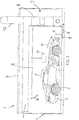
- Figure 1 shows a transportable vehicle enclosure generally referenced 1 for painting vehicles such as vehicle 2.
- the enclosure incorporates a floor 3, a ceiling 4 and a rear portion 5.
- the enclosure may incorporate an explosion relief panel.
- the explosion relief panel may be incorporated into the ceiling of the enclosure.
- the front portion 6 incorporates doors 7 and 8 as shown in Figure 2 which may be opened to permit the passage into and out of the enclosure by for example a motor vehicle.
- Treated air passes through inlet plenum 9 before reaching the vehicle containing portion of the enclosure.
- the air flows substantially diagonally across the length of the inside of the enclosure as illustrated by the series of arrows 10-14.
- the air exits at the vehicle containing area at the rearmost portion of the enclosure where a lower extraction duct 15 is integrated into the floor.
- a track 16 extends along the side and rearmost portions of the inner surface of the enclosure.
- Track 16 may be used to secure an infrared dryer unit 17.
- the infrared dryer unit may displace along said track in order to allow the positioning of the dryer in close proximity to the particular area of the vehicle.
- Track 16 serves to displace the dryer unit longitudinally.
- the dryer unit may also be displaceable in a direction orthogonal to the floor. This would allow the dryer unit to be positioned at different heights in order to target different locations.
- the dryer unit may be configured to accommodate a degree of rotation about an axis normal to the floor.
- the dryer unit may also tilt forwards and backwards.
- an air handling unit 18 is provided in the rear portion 5 of the enclosure.
- the air handling unit may incorporate a direct gas-fired burner with input and extraction fans.
- the input and extraction fans may be twin input and extraction fans with a power rating of 3-4kW.
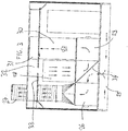
- a bespoke gas storage area 19 is provided (as shown in Figure 2 ) with a plurality of gas cylinders.
- gas bottles may simply be provided at substantially ground level outside of the enclosure.
- An extraction duct 20 is provided and may advantageously reduce emissions under 10mg/m3 at a 15 meter per second velocity.
- the lower extraction duct 15 may incorporate a gridded floor section with two stages of filtration beneath the section to ensure effective removal of particulate matter.
- the inlet plenum 9 may incorporate a TA600 high particle filter i.e. a 600 micro particle performance rated filter with a 6% potassium permanganate impregnated filter media suitable for removing airborne pollutants.
- the floor may be an integrated structural floor which will provide additional structural strength which would be particularly advantageous during relocation.
- the entire air handling plant is provided above the ground.
- only part of the floor incorporates vents.
- the floor is relatively shallow.
- a paint store 21 may be provided in the rear portion.
- An equipment store 22 may also be provided in the rear portion.
- Door 23 may be provided to facilitate access to the rear portion from the outside whilst door 24 provides access from the inside of the enclosure to the rear portion.
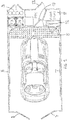
- FIG. 3 shows an embodiment of the air handling unit in detail.
- the dashed arrows represent potential heated air circulating through the lower extraction duct 25 out.
- An extraction fan 26 applies suction in order to cause air to be drawn up and out the extraction duct 27.
- the air handling unit is in the spray cycle mode of use during which enclosed air is filtered and extracted from the enclosure whilst fresh air is drawn through the inlet duct (which may be louvered in the rear wall) and to the burner for treatment.
- the inlet of air is driven by an inlet fan 29 which causes the flow of air through the direct fired gas burner 30 into the top plenum 31.
- An inlet plenum 32 is also provided together with an inlet filter 33.
- a two-way change-over flap box 34 is shown in a position where fresh air is drawn into the burner by the inlet/recirculation fan 29 whilst extracted air is drawn out of the enclosure via extractor fan 26.
- Figure 4 shows an alternative mode of use where the two-way change-over flap box 34 causes air originating from the enclosure to be re-circulated by the action of re-circulation fan 29.
- the gas burner 30 would potentially reheat the air obtained from the enclosure in order to eventually reach in the enclosure a temperature suitable for the baking mode of operation.
- the extraction fan 26 may draw air from the inlet, in practice the operation of the extraction fan would not take place or be considerably reduced.
- Figures 3 and 4 are examples of the provision of a full heat facility both on a spray and a bake cycle which enables the drying of water based and two pack materials.
- the air handling plant may raise the temperature of the incoming air at a temperature which could be as low as -5° Celsius to 22° Celsius to enable a suitable spray temperature to be achieved.
- a temperature of 60° Celsius may be achieved over the entire vehicle contained in the enclosure to ensure complete curing of 2 pack materials.
- the booth automatically changes from spray to recirculation once a period of no paint spraying has taken place for more than 4 minutes.
- This action may be controlled by a hot wire air flow sensor in the compressed air line to the spray gun with an input into the PLC and in turn controls the automatic standby mode, reducing the fan speed to 25% and thus reducing the gas consumption by 75%.
- the flap box changes to recirculation with the action of a pneumatic ram controlled by a solenoid.
- the flap box 34 may remain in recirculation mode until the painter applies further coats of paint or changes to bake cycle.
- the extracted air may be filtered via a two stage filter, reducing emissions below and potentially substantially below 10mg per cubic meter of particle emissions to comply with stringent environmental requirements.
- the vehicle enclosure may comprise a low bake oven for repairs and paintwork on cars.
- the enclosure may advantageously be built of a single mono block unit which may be easily transported, re-loaded and unloaded in a different location.
- the enclosure is a mono-block it allows the full painting and baking operation to be carried out, producing first and second temperature levels suitable for each stage, in a transportable mono-block in any detached isolated location and in any external temperature condition.
- the enclosure comprises its own direct gas-fired air handling unit with the spray and bake functions producing approximately 20° Celsius and 60° Celsius respectfully. It will also have a fully integrated paint mixing area, complete with self-contained gas storage, along with lockers for tools and equipment storage.
- the enclosure comprises a fully self-contained spray booth which may be conveniently transported across long distances as required. It may facilitate relatively small repairs to be made on the site of a car dealership rather than requiring transport to a multi-stage body shop.
Landscapes
- Engineering & Computer Science (AREA)
- Mechanical Engineering (AREA)
- General Engineering & Computer Science (AREA)
- Drying Of Solid Materials (AREA)
- Details Or Accessories Of Spraying Plant Or Apparatus (AREA)
- Coating Apparatus (AREA)
- Application Of Or Painting With Fluid Materials (AREA)
- Thermotherapy And Cooling Therapy Devices (AREA)
- Medicines Containing Plant Substances (AREA)
Claims (16)
- Enceinte transportable pour véhicules (1) pour peindre des véhicules, comprenant des parties de plafond (4) et de plancher (3) et des première, deuxième, troisième et quatrième parties latérales, dans laquelle lesdites première et troisième et lesdites deuxième et quatrième parties latérales sont disposées de manière opposée, ladite première partie latérale étant configurée pour permettre l'accès des véhicules ; moyennant quoi, en utilisation, un véhicule peut être placé à l'intérieur de ladite enceinte ; ladite enceinte comprenant en outre une unité de traitement de l'air (18) pour produire un premier niveau de température à l'intérieur de ladite enceinte (1) adapté à un mode de fonctionnement de pulvérisation et pour produire un deuxième niveau de température à l'intérieur de ladite enceinte approprié pour un mode de fonctionnement par cuisson ; dans laquelle ladite partie de plancher comprend des entretoises s'étendant longitudinalement et latéralement ; et dans laquelle ladite enceinte est rectangulaire en vue de dessus ; caractérisée en ce que ladite unité de traitement de l'air est située à l'intérieur de ladite enceinte adjacente à ladite troisième partie latérale.
- Enceinte selon la revendication 1, qui est formée comme un monobloc approprié pour le chargement sur un transporteur et le déchargement d'un transporteur, dans laquelle ladite unité de traitement de l'air (18) est solidaire dudit monobloc.
- Enceinte selon la revendication 1 ou la revendication 2, dans laquelle ladite unité de traitement de l'air (18) incorpore un conduit d'air supérieur pour sortir l'air dans une partie de ladite enceinte contenant un véhicule, soit au premier soit au deuxième niveau de température.
- Enceinte selon la revendication 3, dans laquelle un conduit d'extraction inférieur (15) est situé de manière adjacente à ladite unité de traitement de l'air dans ladite partie de plancher ; moyennant quoi l'air circule sensiblement en diagonale entre ledit conduit d'air supérieur et ledit conduit d'extraction inférieur.
- Enceinte selon l'une des revendications précédentes, dans laquelle ladite unité de traitement de l'air incorpore un réchauffeur ; ledit réchauffeur étant un brûleur à gaz à feu direct qui est capable de chauffer l'air à la fois dans ledit mode de fonctionnement de pulvérisation et dans ledit mode de fonctionnement de cuisson.
- Enceinte selon l'une quelconque des revendications 1 à 4, dans laquelle ladite unité de traitement de l'air (18) incorpore un réchauffeur ; une entrée d'air frais ; et un contrôleur de débit d'air et qui, dans une première position, permet à l'air frais de s'écouler vers ledit réchauffeur et qui, dans une deuxième position, permet à l'air de s'écouler de l'intérieur de ladite enceinte vers ledit réchauffeur afin de faire recirculer ledit air.
- Enceinte selon la revendication 6, dans laquelle ledit contrôleur de débit d'air est configuré pour passer automatiquement de ladite première à ladite deuxième position après qu'une période de temps prédéterminée s'écoule pendant laquelle aucune pulvérisation ne se produit.
- Enceinte selon la revendication 7, comprenant en outre un pistolet de pulvérisation avec une conduite d'air comprimé ; un capteur de débit d'air étant prévu pour détecter le débit d'air dans ladite conduite d'air comprimé ; ledit contrôleur passe de ladite première position à ladite deuxième position en fonction de la présence ou de l'absence détectée de débit d'air.
- Enceinte selon l'une quelconque des revendications précédentes, dans laquelle moins de 3/4 de la surface de ladite troisième partie latérale est occupée par ladite installation de traitement de l'air.
- Enceinte selon la revendication 4, dans laquelle ladite enceinte comprend un conduit d'extraction inférieur (15) qui est situé entre des montants s'étendant latéralement.
- Enceinte selon la revendication 4, dans laquelle ledit conduit d'extraction inférieur (15) incorpore un filtre d'extraction.
- Enceinte selon l'une quelconque des revendications précédentes, dans laquelle l'air émis par ladite enceinte passe à travers un filtre à deux étages ou plus.
- Enceinte selon l'une quelconque des revendications précédentes, qui est formée comme un seul bloc intégral pour le transport.
- Enceinte selon l'une quelconque des revendications précédentes, comprenant en outre une unité de séchage (17) qui est déplaçable le long d'un rail à l'intérieur de l'enceinte.
- Enceinte selon la revendication 14, dans laquelle ladite unité de séchage (17) est déplaçable au moins longitudinalement le long d'un rail à l'intérieur de l'enceinte et de manière rotative au moins autour d'un axe normal au plancher de l'enceinte.
- Enceinte selon l'une quelconque des revendications précédentes, dans laquelle ladite troisième partie latérale abrite à la fois ladite unité de traitement de l'air et un magasin qui est accessible par une porte intérieure.
Priority Applications (2)
| Application Number | Priority Date | Filing Date | Title |
|---|---|---|---|
| EP22205041.1A EP4147788A1 (fr) | 2012-07-25 | 2013-07-25 | Parties de traitement d'air et enceintes de véhicule |
| EP20212424.4A EP3815793B1 (fr) | 2012-07-25 | 2013-07-25 | Cabine de traitement transportable pour véhicules |
Applications Claiming Priority (4)
| Application Number | Priority Date | Filing Date | Title |
|---|---|---|---|
| GBGB1213234.6A GB201213234D0 (fr) | 2012-07-25 | 2012-07-25 | |
| GB1219589.7A GB2499285B (en) | 2012-07-25 | 2012-10-31 | Transportable vehicle enclosures |
| PCT/GB2013/051999 WO2014016606A1 (fr) | 2012-07-25 | 2013-07-25 | Enceinte transportable pour des opérations de peinture et de réticulation sur des véhicules |
| EP13742714.2A EP2877295B1 (fr) | 2012-07-25 | 2013-07-25 | Enceinte transportable pour des opérations de peinture et de réticulation sur des véhicules |
Related Parent Applications (2)
| Application Number | Title | Priority Date | Filing Date |
|---|---|---|---|
| EP13742714.2A Division EP2877295B1 (fr) | 2012-07-25 | 2013-07-25 | Enceinte transportable pour des opérations de peinture et de réticulation sur des véhicules |
| EP13742714.2A Division-Into EP2877295B1 (fr) | 2012-07-25 | 2013-07-25 | Enceinte transportable pour des opérations de peinture et de réticulation sur des véhicules |
Related Child Applications (2)
| Application Number | Title | Priority Date | Filing Date |
|---|---|---|---|
| EP20212424.4A Division EP3815793B1 (fr) | 2012-07-25 | 2013-07-25 | Cabine de traitement transportable pour véhicules |
| EP22205041.1A Division EP4147788A1 (fr) | 2012-07-25 | 2013-07-25 | Parties de traitement d'air et enceintes de véhicule |
Publications (2)
| Publication Number | Publication Date |
|---|---|
| EP3626355A1 EP3626355A1 (fr) | 2020-03-25 |
| EP3626355B1 true EP3626355B1 (fr) | 2020-12-09 |
Family
ID=46881950
Family Applications (4)
| Application Number | Title | Priority Date | Filing Date |
|---|---|---|---|
| EP20212424.4A Active EP3815793B1 (fr) | 2012-07-25 | 2013-07-25 | Cabine de traitement transportable pour véhicules |
| EP13742714.2A Active EP2877295B1 (fr) | 2012-07-25 | 2013-07-25 | Enceinte transportable pour des opérations de peinture et de réticulation sur des véhicules |
| EP22205041.1A Withdrawn EP4147788A1 (fr) | 2012-07-25 | 2013-07-25 | Parties de traitement d'air et enceintes de véhicule |
| EP19204196.0A Active EP3626355B1 (fr) | 2012-07-25 | 2013-07-25 | Cabine de traitement transportable pour vehicules |
Family Applications Before (3)
| Application Number | Title | Priority Date | Filing Date |
|---|---|---|---|
| EP20212424.4A Active EP3815793B1 (fr) | 2012-07-25 | 2013-07-25 | Cabine de traitement transportable pour véhicules |
| EP13742714.2A Active EP2877295B1 (fr) | 2012-07-25 | 2013-07-25 | Enceinte transportable pour des opérations de peinture et de réticulation sur des véhicules |
| EP22205041.1A Withdrawn EP4147788A1 (fr) | 2012-07-25 | 2013-07-25 | Parties de traitement d'air et enceintes de véhicule |
Country Status (7)
| Country | Link |
|---|---|
| US (1) | US9724720B2 (fr) |
| EP (4) | EP3815793B1 (fr) |
| AU (1) | AU2013294757B2 (fr) |
| CA (1) | CA2913522C (fr) |
| ES (3) | ES2936639T3 (fr) |
| GB (2) | GB201213234D0 (fr) |
| WO (1) | WO2014016606A1 (fr) |
Families Citing this family (10)
| Publication number | Priority date | Publication date | Assignee | Title |
|---|---|---|---|---|
| US11364515B2 (en) | 2012-07-25 | 2022-06-21 | David John Utting | Transportable vehicle enclosures |
| US20150017897A1 (en) * | 2013-07-10 | 2015-01-15 | Thomas Wiliams | System and Method for Maintaining Airflow within an Inflatable Booth |
| FR3013994B1 (fr) * | 2013-12-03 | 2015-11-27 | Corelec Equipements | Installation de thermolaquage |
| CN104028408B (zh) * | 2014-06-05 | 2016-11-16 | 江苏中一汽车机械设备制造有限公司 | 并联式打磨、喷漆、烘干钣喷系统 |
| PT3288687T (pt) * | 2015-04-30 | 2019-10-08 | Usi Italia S R L | Aparelho para pintura e/ou tratamento de veículos e outros componentes no geral |
| AU2016100382B4 (en) * | 2016-04-08 | 2016-06-30 | Action Smart Group IP Pty Ltd | Transportable body for paint spraying field |
| GB2567632B (en) * | 2017-10-16 | 2022-05-04 | John Utting David | A transportable vehicle enclosure for inspecting vehicles |
| CN111570170A (zh) * | 2020-06-03 | 2020-08-25 | 黄娇健 | 一种机械零件加工用喷涂装置 |
| GB2600160B (en) | 2020-10-26 | 2023-07-26 | John Utting David | Transportable modules and/or vehicle enclosures |
| AT528072B1 (de) * | 2024-03-01 | 2026-01-15 | Krammer Rupert | Lackier- und Trockenkabine und Verfahren zu deren Betrieb |
Family Cites Families (19)
| Publication number | Priority date | Publication date | Assignee | Title |
|---|---|---|---|---|
| JPS52116957A (en) * | 1976-03-26 | 1977-09-30 | Nippon Paint Co Ltd | One room type paint baking and drying apparatus |
| US4265029A (en) * | 1979-12-04 | 1981-05-05 | Jenkins Kenneth A | Motor vehicle dryer stand |
| GB2136947B (en) * | 1982-11-04 | 1987-09-03 | Rich Limited William | Spray booth air handling unit |
| US4685385A (en) * | 1984-12-20 | 1987-08-11 | Rich Colin W | Refinishing unit |
| US5113600A (en) * | 1989-09-14 | 1992-05-19 | Binks Manufacturing Company | Combination paint spray booth-drying oven with single air fan |
| DE4327751A1 (de) * | 1993-08-18 | 1995-02-23 | Ulrich Dohl | Mobiler zusammenschiebbarer Vielzweck-Werkstattwagen, oder Baustellen-Aufenthaltswagen |
| US5853215A (en) * | 1995-03-22 | 1998-12-29 | Lowery; Robert S. | Mobile spraybooth workstation |
| US5643077A (en) * | 1995-06-16 | 1997-07-01 | Ayer; Jacqueline | Continually optimized, variable flow rate ventilation system |
| AT5208U1 (de) | 2001-03-27 | 2002-04-25 | Riri Privatstiftung | Transportable werkstätte |
| US7045013B2 (en) * | 2003-12-03 | 2006-05-16 | Garmat Usa | Spray booth systems and methods for accelerating curing times |
| CA2564476C (fr) | 2004-05-26 | 2011-08-09 | Alloy Wheel Repair Specialists, Inc. | Installation de remise en etat de roues mobiles |
| US7455580B2 (en) * | 2004-11-24 | 2008-11-25 | San Ford Machinery Co., Ltd. | Dry spray device |
| US7798547B2 (en) | 2005-08-04 | 2010-09-21 | Antaya Bruce C | Portable paint booth |
| US7974739B2 (en) * | 2006-06-27 | 2011-07-05 | Illinois Tool Works Inc. | System and method having arm with cable passage through joint to infrared lamp |
| CN101254846A (zh) * | 2007-03-02 | 2008-09-03 | 中国国际海运集装箱(集团)股份有限公司 | 台架箱底架的制作方法 |
| ES2363895B1 (es) * | 2008-08-04 | 2012-07-04 | Roisber Servicios, S.L | Cabina de pintura movil |
| DE202009003182U1 (de) * | 2009-03-10 | 2009-05-20 | Kufahl, Gunnar | Mobile PKW-Lackierkabine |
| US20100272915A1 (en) * | 2009-04-28 | 2010-10-28 | Seth Anthony Laws | Portable spray booth with air handling system |
| GB2486703B (en) * | 2010-12-23 | 2013-04-10 | Spraybooth Technology Ltd | Spray booths |
-
2012
- 2012-07-25 GB GBGB1213234.6A patent/GB201213234D0/en not_active Ceased
- 2012-10-31 GB GB1219589.7A patent/GB2499285B/en active Active
-
2013
- 2013-07-25 ES ES20212424T patent/ES2936639T3/es active Active
- 2013-07-25 EP EP20212424.4A patent/EP3815793B1/fr active Active
- 2013-07-25 CA CA2913522A patent/CA2913522C/fr active Active
- 2013-07-25 ES ES13742714T patent/ES2811248T3/es active Active
- 2013-07-25 WO PCT/GB2013/051999 patent/WO2014016606A1/fr not_active Ceased
- 2013-07-25 AU AU2013294757A patent/AU2013294757B2/en active Active
- 2013-07-25 EP EP13742714.2A patent/EP2877295B1/fr active Active
- 2013-07-25 EP EP22205041.1A patent/EP4147788A1/fr not_active Withdrawn
- 2013-07-25 EP EP19204196.0A patent/EP3626355B1/fr active Active
- 2013-07-25 ES ES19204196T patent/ES2862394T3/es active Active
- 2013-07-25 US US14/417,523 patent/US9724720B2/en active Active
Non-Patent Citations (1)
| Title |
|---|
| None * |
Also Published As
| Publication number | Publication date |
|---|---|
| CA2913522C (fr) | 2021-11-23 |
| EP3815793B1 (fr) | 2022-12-14 |
| GB2499285B (en) | 2014-03-19 |
| ES2811248T3 (es) | 2021-03-11 |
| EP2877295A1 (fr) | 2015-06-03 |
| AU2013294757A1 (en) | 2015-02-26 |
| US20150273509A1 (en) | 2015-10-01 |
| EP4147788A1 (fr) | 2023-03-15 |
| GB2499285A (en) | 2013-08-14 |
| GB201213234D0 (fr) | 2012-09-05 |
| EP3626355A1 (fr) | 2020-03-25 |
| US9724720B2 (en) | 2017-08-08 |
| WO2014016606A1 (fr) | 2014-01-30 |
| EP3815793A1 (fr) | 2021-05-05 |
| ES2862394T3 (es) | 2021-10-07 |
| AU2013294757B2 (en) | 2017-09-21 |
| EP2877295B1 (fr) | 2020-04-08 |
| GB201219589D0 (en) | 2012-12-12 |
| ES2936639T3 (es) | 2023-03-21 |
| CA2913522A1 (fr) | 2014-01-30 |
Similar Documents
| Publication | Publication Date | Title |
|---|---|---|
| EP3626355B1 (fr) | Cabine de traitement transportable pour vehicules | |
| CN111249857B (zh) | 一种voc废气处理净化装置及具有其的烤漆房 | |
| EP3215278B1 (fr) | Cabine de peinture et sa ventilation | |
| US7666077B1 (en) | Paint booth arrangement and method for directing airflow | |
| US9643203B2 (en) | Spray booths | |
| CN107890685B (zh) | 应用于喷漆烤漆工艺的节能环保循环式废气处理系统 | |
| CN102439386A (zh) | 用于给工件设置涂层的方法和涂层设备 | |
| CN107029928A (zh) | 用于大型风电产品的自动化机器人喷涂生产线 | |
| US11759816B2 (en) | Transportable vehicle enclosures | |
| AU2016100382B4 (en) | Transportable body for paint spraying field | |
| EP3356055B1 (fr) | Système de sécurité de cabine de travail pour atelier de réparation de carrosserie automobile | |
| US5133690A (en) | Booth with controlled environment for aircraft maintenance | |
| CN209101288U (zh) | 涂装治具焚烧清洁炉 | |
| CN223148537U (zh) | 一种舰艇器材机动保障方舱 | |
| GB2532047A (en) | Ovens for industrial processes | |
| JP2006118784A (ja) | 焼付乾燥炉 | |
| CN104588293A (zh) | 远红外线加热汽车烤漆房 |
Legal Events
| Date | Code | Title | Description |
|---|---|---|---|
| PUAI | Public reference made under article 153(3) epc to a published international application that has entered the european phase |
Free format text: ORIGINAL CODE: 0009012 |
|
| STAA | Information on the status of an ep patent application or granted ep patent |
Free format text: STATUS: THE APPLICATION HAS BEEN PUBLISHED |
|
| AC | Divisional application: reference to earlier application |
Ref document number: 2877295 Country of ref document: EP Kind code of ref document: P |
|
| AK | Designated contracting states |
Kind code of ref document: A1 Designated state(s): AL AT BE BG CH CY CZ DE DK EE ES FI FR GB GR HR HU IE IS IT LI LT LU LV MC MK MT NL NO PL PT RO RS SE SI SK SM TR |
|
| STAA | Information on the status of an ep patent application or granted ep patent |
Free format text: STATUS: REQUEST FOR EXAMINATION WAS MADE |
|
| 17P | Request for examination filed |
Effective date: 20200618 |
|
| RBV | Designated contracting states (corrected) |
Designated state(s): AL AT BE BG CH CY CZ DE DK EE ES FI FR GB GR HR HU IE IS IT LI LT LU LV MC MK MT NL NO PL PT RO RS SE SI SK SM TR |
|
| GRAP | Despatch of communication of intention to grant a patent |
Free format text: ORIGINAL CODE: EPIDOSNIGR1 |
|
| STAA | Information on the status of an ep patent application or granted ep patent |
Free format text: STATUS: GRANT OF PATENT IS INTENDED |
|
| GRAS | Grant fee paid |
Free format text: ORIGINAL CODE: EPIDOSNIGR3 |
|
| RIC1 | Information provided on ipc code assigned before grant |
Ipc: F26B 25/06 20060101ALI20200925BHEP Ipc: F26B 3/30 20060101ALN20200925BHEP Ipc: B05B 16/80 20180101ALI20200925BHEP Ipc: F26B 3/28 20060101ALN20200925BHEP Ipc: B05B 16/20 20180101AFI20200925BHEP Ipc: B05B 16/60 20180101ALI20200925BHEP Ipc: F26B 23/02 20060101ALN20200925BHEP |
|
| GRAA | (expected) grant |
Free format text: ORIGINAL CODE: 0009210 |
|
| STAA | Information on the status of an ep patent application or granted ep patent |
Free format text: STATUS: THE PATENT HAS BEEN GRANTED |
|
| INTG | Intention to grant announced |
Effective date: 20201023 |
|
| AC | Divisional application: reference to earlier application |
Ref document number: 2877295 Country of ref document: EP Kind code of ref document: P |
|
| AK | Designated contracting states |
Kind code of ref document: B1 Designated state(s): AL AT BE BG CH CY CZ DE DK EE ES FI FR GB GR HR HU IE IS IT LI LT LU LV MC MK MT NL NO PL PT RO RS SE SI SK SM TR |
|
| REG | Reference to a national code |
Ref country code: GB Ref legal event code: FG4D |
|
| REG | Reference to a national code |
Ref country code: AT Ref legal event code: REF Ref document number: 1342870 Country of ref document: AT Kind code of ref document: T Effective date: 20201215 Ref country code: CH Ref legal event code: EP |
|
| REG | Reference to a national code |
Ref country code: DE Ref legal event code: R096 Ref document number: 602013074707 Country of ref document: DE |
|
| REG | Reference to a national code |
Ref country code: IE Ref legal event code: FG4D |
|
| REG | Reference to a national code |
Ref country code: SE Ref legal event code: TRGR |
|
| REG | Reference to a national code |
Ref country code: NL Ref legal event code: FP |
|
| PG25 | Lapsed in a contracting state [announced via postgrant information from national office to epo] |
Ref country code: RS Free format text: LAPSE BECAUSE OF FAILURE TO SUBMIT A TRANSLATION OF THE DESCRIPTION OR TO PAY THE FEE WITHIN THE PRESCRIBED TIME-LIMIT Effective date: 20201209 Ref country code: FI Free format text: LAPSE BECAUSE OF FAILURE TO SUBMIT A TRANSLATION OF THE DESCRIPTION OR TO PAY THE FEE WITHIN THE PRESCRIBED TIME-LIMIT Effective date: 20201209 Ref country code: GR Free format text: LAPSE BECAUSE OF FAILURE TO SUBMIT A TRANSLATION OF THE DESCRIPTION OR TO PAY THE FEE WITHIN THE PRESCRIBED TIME-LIMIT Effective date: 20210310 Ref country code: NO Free format text: LAPSE BECAUSE OF FAILURE TO SUBMIT A TRANSLATION OF THE DESCRIPTION OR TO PAY THE FEE WITHIN THE PRESCRIBED TIME-LIMIT Effective date: 20210309 |
|
| REG | Reference to a national code |
Ref country code: AT Ref legal event code: MK05 Ref document number: 1342870 Country of ref document: AT Kind code of ref document: T Effective date: 20201209 |
|
| PG25 | Lapsed in a contracting state [announced via postgrant information from national office to epo] |
Ref country code: BG Free format text: LAPSE BECAUSE OF FAILURE TO SUBMIT A TRANSLATION OF THE DESCRIPTION OR TO PAY THE FEE WITHIN THE PRESCRIBED TIME-LIMIT Effective date: 20210309 Ref country code: LV Free format text: LAPSE BECAUSE OF FAILURE TO SUBMIT A TRANSLATION OF THE DESCRIPTION OR TO PAY THE FEE WITHIN THE PRESCRIBED TIME-LIMIT Effective date: 20201209 |
|
| PG25 | Lapsed in a contracting state [announced via postgrant information from national office to epo] |
Ref country code: HR Free format text: LAPSE BECAUSE OF FAILURE TO SUBMIT A TRANSLATION OF THE DESCRIPTION OR TO PAY THE FEE WITHIN THE PRESCRIBED TIME-LIMIT Effective date: 20201209 |
|
| REG | Reference to a national code |
Ref country code: LT Ref legal event code: MG9D |
|
| PG25 | Lapsed in a contracting state [announced via postgrant information from national office to epo] |
Ref country code: LT Free format text: LAPSE BECAUSE OF FAILURE TO SUBMIT A TRANSLATION OF THE DESCRIPTION OR TO PAY THE FEE WITHIN THE PRESCRIBED TIME-LIMIT Effective date: 20201209 Ref country code: PT Free format text: LAPSE BECAUSE OF FAILURE TO SUBMIT A TRANSLATION OF THE DESCRIPTION OR TO PAY THE FEE WITHIN THE PRESCRIBED TIME-LIMIT Effective date: 20210409 Ref country code: RO Free format text: LAPSE BECAUSE OF FAILURE TO SUBMIT A TRANSLATION OF THE DESCRIPTION OR TO PAY THE FEE WITHIN THE PRESCRIBED TIME-LIMIT Effective date: 20201209 Ref country code: CZ Free format text: LAPSE BECAUSE OF FAILURE TO SUBMIT A TRANSLATION OF THE DESCRIPTION OR TO PAY THE FEE WITHIN THE PRESCRIBED TIME-LIMIT Effective date: 20201209 Ref country code: SK Free format text: LAPSE BECAUSE OF FAILURE TO SUBMIT A TRANSLATION OF THE DESCRIPTION OR TO PAY THE FEE WITHIN THE PRESCRIBED TIME-LIMIT Effective date: 20201209 Ref country code: SM Free format text: LAPSE BECAUSE OF FAILURE TO SUBMIT A TRANSLATION OF THE DESCRIPTION OR TO PAY THE FEE WITHIN THE PRESCRIBED TIME-LIMIT Effective date: 20201209 Ref country code: EE Free format text: LAPSE BECAUSE OF FAILURE TO SUBMIT A TRANSLATION OF THE DESCRIPTION OR TO PAY THE FEE WITHIN THE PRESCRIBED TIME-LIMIT Effective date: 20201209 |
|
| PG25 | Lapsed in a contracting state [announced via postgrant information from national office to epo] |
Ref country code: AT Free format text: LAPSE BECAUSE OF FAILURE TO SUBMIT A TRANSLATION OF THE DESCRIPTION OR TO PAY THE FEE WITHIN THE PRESCRIBED TIME-LIMIT Effective date: 20201209 Ref country code: PL Free format text: LAPSE BECAUSE OF FAILURE TO SUBMIT A TRANSLATION OF THE DESCRIPTION OR TO PAY THE FEE WITHIN THE PRESCRIBED TIME-LIMIT Effective date: 20201209 |
|
| REG | Reference to a national code |
Ref country code: DE Ref legal event code: R097 Ref document number: 602013074707 Country of ref document: DE |
|
| PG25 | Lapsed in a contracting state [announced via postgrant information from national office to epo] |
Ref country code: IS Free format text: LAPSE BECAUSE OF FAILURE TO SUBMIT A TRANSLATION OF THE DESCRIPTION OR TO PAY THE FEE WITHIN THE PRESCRIBED TIME-LIMIT Effective date: 20210409 |
|
| REG | Reference to a national code |
Ref country code: ES Ref legal event code: FG2A Ref document number: 2862394 Country of ref document: ES Kind code of ref document: T3 Effective date: 20211007 |
|
| PLBE | No opposition filed within time limit |
Free format text: ORIGINAL CODE: 0009261 |
|
| STAA | Information on the status of an ep patent application or granted ep patent |
Free format text: STATUS: NO OPPOSITION FILED WITHIN TIME LIMIT |
|
| PG25 | Lapsed in a contracting state [announced via postgrant information from national office to epo] |
Ref country code: AL Free format text: LAPSE BECAUSE OF FAILURE TO SUBMIT A TRANSLATION OF THE DESCRIPTION OR TO PAY THE FEE WITHIN THE PRESCRIBED TIME-LIMIT Effective date: 20201209 |
|
| 26N | No opposition filed |
Effective date: 20210910 |
|
| PG25 | Lapsed in a contracting state [announced via postgrant information from national office to epo] |
Ref country code: DK Free format text: LAPSE BECAUSE OF FAILURE TO SUBMIT A TRANSLATION OF THE DESCRIPTION OR TO PAY THE FEE WITHIN THE PRESCRIBED TIME-LIMIT Effective date: 20201209 Ref country code: SI Free format text: LAPSE BECAUSE OF FAILURE TO SUBMIT A TRANSLATION OF THE DESCRIPTION OR TO PAY THE FEE WITHIN THE PRESCRIBED TIME-LIMIT Effective date: 20201209 |
|
| REG | Reference to a national code |
Ref country code: CH Ref legal event code: PL |
|
| PG25 | Lapsed in a contracting state [announced via postgrant information from national office to epo] |
Ref country code: MC Free format text: LAPSE BECAUSE OF FAILURE TO SUBMIT A TRANSLATION OF THE DESCRIPTION OR TO PAY THE FEE WITHIN THE PRESCRIBED TIME-LIMIT Effective date: 20201209 |
|
| REG | Reference to a national code |
Ref country code: BE Ref legal event code: MM Effective date: 20210731 |
|
| PG25 | Lapsed in a contracting state [announced via postgrant information from national office to epo] |
Ref country code: LI Free format text: LAPSE BECAUSE OF NON-PAYMENT OF DUE FEES Effective date: 20210731 Ref country code: CH Free format text: LAPSE BECAUSE OF NON-PAYMENT OF DUE FEES Effective date: 20210731 |
|
| PG25 | Lapsed in a contracting state [announced via postgrant information from national office to epo] |
Ref country code: IS Free format text: LAPSE BECAUSE OF FAILURE TO SUBMIT A TRANSLATION OF THE DESCRIPTION OR TO PAY THE FEE WITHIN THE PRESCRIBED TIME-LIMIT Effective date: 20210409 Ref country code: LU Free format text: LAPSE BECAUSE OF NON-PAYMENT OF DUE FEES Effective date: 20210725 |
|
| PG25 | Lapsed in a contracting state [announced via postgrant information from national office to epo] |
Ref country code: BE Free format text: LAPSE BECAUSE OF NON-PAYMENT OF DUE FEES Effective date: 20210731 |
|
| PG25 | Lapsed in a contracting state [announced via postgrant information from national office to epo] |
Ref country code: CY Free format text: LAPSE BECAUSE OF FAILURE TO SUBMIT A TRANSLATION OF THE DESCRIPTION OR TO PAY THE FEE WITHIN THE PRESCRIBED TIME-LIMIT Effective date: 20201209 |
|
| PG25 | Lapsed in a contracting state [announced via postgrant information from national office to epo] |
Ref country code: HU Free format text: LAPSE BECAUSE OF FAILURE TO SUBMIT A TRANSLATION OF THE DESCRIPTION OR TO PAY THE FEE WITHIN THE PRESCRIBED TIME-LIMIT; INVALID AB INITIO Effective date: 20130725 |
|
| PG25 | Lapsed in a contracting state [announced via postgrant information from national office to epo] |
Ref country code: MK Free format text: LAPSE BECAUSE OF FAILURE TO SUBMIT A TRANSLATION OF THE DESCRIPTION OR TO PAY THE FEE WITHIN THE PRESCRIBED TIME-LIMIT Effective date: 20201209 |
|
| PG25 | Lapsed in a contracting state [announced via postgrant information from national office to epo] |
Ref country code: MT Free format text: LAPSE BECAUSE OF FAILURE TO SUBMIT A TRANSLATION OF THE DESCRIPTION OR TO PAY THE FEE WITHIN THE PRESCRIBED TIME-LIMIT Effective date: 20201209 |
|
| PGFP | Annual fee paid to national office [announced via postgrant information from national office to epo] |
Ref country code: NL Payment date: 20250721 Year of fee payment: 13 |
|
| PGFP | Annual fee paid to national office [announced via postgrant information from national office to epo] |
Ref country code: ES Payment date: 20250801 Year of fee payment: 13 |
|
| PGFP | Annual fee paid to national office [announced via postgrant information from national office to epo] |
Ref country code: DE Payment date: 20250723 Year of fee payment: 13 |
|
| PGFP | Annual fee paid to national office [announced via postgrant information from national office to epo] |
Ref country code: IT Payment date: 20250709 Year of fee payment: 13 |
|
| PGFP | Annual fee paid to national office [announced via postgrant information from national office to epo] |
Ref country code: GB Payment date: 20250716 Year of fee payment: 13 |
|
| PGFP | Annual fee paid to national office [announced via postgrant information from national office to epo] |
Ref country code: FR Payment date: 20250716 Year of fee payment: 13 |
|
| PGFP | Annual fee paid to national office [announced via postgrant information from national office to epo] |
Ref country code: SE Payment date: 20250716 Year of fee payment: 13 |
|
| PGFP | Annual fee paid to national office [announced via postgrant information from national office to epo] |
Ref country code: IE Payment date: 20250711 Year of fee payment: 13 |
|
| PG25 | Lapsed in a contracting state [announced via postgrant information from national office to epo] |
Ref country code: TR Free format text: LAPSE BECAUSE OF FAILURE TO SUBMIT A TRANSLATION OF THE DESCRIPTION OR TO PAY THE FEE WITHIN THE PRESCRIBED TIME-LIMIT Effective date: 20201209 |