EP3626392A1 - Bearbeitungszentrum für uhrenkomponenten - Google Patents
Bearbeitungszentrum für uhrenkomponenten Download PDFInfo
- Publication number
- EP3626392A1 EP3626392A1 EP18195543.6A EP18195543A EP3626392A1 EP 3626392 A1 EP3626392 A1 EP 3626392A1 EP 18195543 A EP18195543 A EP 18195543A EP 3626392 A1 EP3626392 A1 EP 3626392A1
- Authority
- EP
- European Patent Office
- Prior art keywords
- machining
- stage
- machining center
- station
- gripper
- Prior art date
- Legal status (The legal status is an assumption and is not a legal conclusion. Google has not performed a legal analysis and makes no representation as to the accuracy of the status listed.)
- Granted
Links
Images




Classifications
-
- B—PERFORMING OPERATIONS; TRANSPORTING
- B23—MACHINE TOOLS; METAL-WORKING NOT OTHERWISE PROVIDED FOR
- B23P—METAL-WORKING NOT OTHERWISE PROVIDED FOR; COMBINED OPERATIONS; UNIVERSAL MACHINE TOOLS
- B23P23/00—Machines or arrangements of machines for performing specified combinations of different metal-working operations not covered by a single other subclass
- B23P23/04—Machines or arrangements of machines for performing specified combinations of different metal-working operations not covered by a single other subclass for both machining and other metal-working operations
-
- B—PERFORMING OPERATIONS; TRANSPORTING
- B23—MACHINE TOOLS; METAL-WORKING NOT OTHERWISE PROVIDED FOR
- B23Q—DETAILS, COMPONENTS, OR ACCESSORIES FOR MACHINE TOOLS, e.g. ARRANGEMENTS FOR COPYING OR CONTROLLING; MACHINE TOOLS IN GENERAL CHARACTERISED BY THE CONSTRUCTION OF PARTICULAR DETAILS OR COMPONENTS; COMBINATIONS OR ASSOCIATIONS OF METAL-WORKING MACHINES, NOT DIRECTED TO A PARTICULAR RESULT
- B23Q39/00—Metal-working machines incorporating a plurality of sub-assemblies, each capable of performing a metal-working operation
- B23Q39/02—Metal-working machines incorporating a plurality of sub-assemblies, each capable of performing a metal-working operation the sub-assemblies being capable of being brought to act at a single operating station
- B23Q39/021—Metal-working machines incorporating a plurality of sub-assemblies, each capable of performing a metal-working operation the sub-assemblies being capable of being brought to act at a single operating station with a plurality of toolheads per workholder, whereby the toolhead is a main spindle, a multispindle, a revolver or the like
-
- B—PERFORMING OPERATIONS; TRANSPORTING
- B23—MACHINE TOOLS; METAL-WORKING NOT OTHERWISE PROVIDED FOR
- B23Q—DETAILS, COMPONENTS, OR ACCESSORIES FOR MACHINE TOOLS, e.g. ARRANGEMENTS FOR COPYING OR CONTROLLING; MACHINE TOOLS IN GENERAL CHARACTERISED BY THE CONSTRUCTION OF PARTICULAR DETAILS OR COMPONENTS; COMBINATIONS OR ASSOCIATIONS OF METAL-WORKING MACHINES, NOT DIRECTED TO A PARTICULAR RESULT
- B23Q39/00—Metal-working machines incorporating a plurality of sub-assemblies, each capable of performing a metal-working operation
- B23Q39/02—Metal-working machines incorporating a plurality of sub-assemblies, each capable of performing a metal-working operation the sub-assemblies being capable of being brought to act at a single operating station
- B23Q39/028—Metal-working machines incorporating a plurality of sub-assemblies, each capable of performing a metal-working operation the sub-assemblies being capable of being brought to act at a single operating station with a plurality of workholder per toolhead in operating position
-
- B—PERFORMING OPERATIONS; TRANSPORTING
- B23—MACHINE TOOLS; METAL-WORKING NOT OTHERWISE PROVIDED FOR
- B23Q—DETAILS, COMPONENTS, OR ACCESSORIES FOR MACHINE TOOLS, e.g. ARRANGEMENTS FOR COPYING OR CONTROLLING; MACHINE TOOLS IN GENERAL CHARACTERISED BY THE CONSTRUCTION OF PARTICULAR DETAILS OR COMPONENTS; COMBINATIONS OR ASSOCIATIONS OF METAL-WORKING MACHINES, NOT DIRECTED TO A PARTICULAR RESULT
- B23Q39/00—Metal-working machines incorporating a plurality of sub-assemblies, each capable of performing a metal-working operation
- B23Q39/04—Metal-working machines incorporating a plurality of sub-assemblies, each capable of performing a metal-working operation the sub-assemblies being arranged to operate simultaneously at different stations, e.g. with an annular work-table moved in steps
- B23Q39/042—Metal-working machines incorporating a plurality of sub-assemblies, each capable of performing a metal-working operation the sub-assemblies being arranged to operate simultaneously at different stations, e.g. with an annular work-table moved in steps with circular arrangement of the sub-assemblies
- B23Q39/044—Metal-working machines incorporating a plurality of sub-assemblies, each capable of performing a metal-working operation the sub-assemblies being arranged to operate simultaneously at different stations, e.g. with an annular work-table moved in steps with circular arrangement of the sub-assemblies having at least one tool station cooperating with each work holder, e.g. multi-spindle lathes
-
- B—PERFORMING OPERATIONS; TRANSPORTING
- B23—MACHINE TOOLS; METAL-WORKING NOT OTHERWISE PROVIDED FOR
- B23Q—DETAILS, COMPONENTS, OR ACCESSORIES FOR MACHINE TOOLS, e.g. ARRANGEMENTS FOR COPYING OR CONTROLLING; MACHINE TOOLS IN GENERAL CHARACTERISED BY THE CONSTRUCTION OF PARTICULAR DETAILS OR COMPONENTS; COMBINATIONS OR ASSOCIATIONS OF METAL-WORKING MACHINES, NOT DIRECTED TO A PARTICULAR RESULT
- B23Q39/00—Metal-working machines incorporating a plurality of sub-assemblies, each capable of performing a metal-working operation
- B23Q39/04—Metal-working machines incorporating a plurality of sub-assemblies, each capable of performing a metal-working operation the sub-assemblies being arranged to operate simultaneously at different stations, e.g. with an annular work-table moved in steps
- B23Q39/042—Metal-working machines incorporating a plurality of sub-assemblies, each capable of performing a metal-working operation the sub-assemblies being arranged to operate simultaneously at different stations, e.g. with an annular work-table moved in steps with circular arrangement of the sub-assemblies
- B23Q39/046—Metal-working machines incorporating a plurality of sub-assemblies, each capable of performing a metal-working operation the sub-assemblies being arranged to operate simultaneously at different stations, e.g. with an annular work-table moved in steps with circular arrangement of the sub-assemblies including a loading and/or unloading station
-
- B—PERFORMING OPERATIONS; TRANSPORTING
- B23—MACHINE TOOLS; METAL-WORKING NOT OTHERWISE PROVIDED FOR
- B23Q—DETAILS, COMPONENTS, OR ACCESSORIES FOR MACHINE TOOLS, e.g. ARRANGEMENTS FOR COPYING OR CONTROLLING; MACHINE TOOLS IN GENERAL CHARACTERISED BY THE CONSTRUCTION OF PARTICULAR DETAILS OR COMPONENTS; COMBINATIONS OR ASSOCIATIONS OF METAL-WORKING MACHINES, NOT DIRECTED TO A PARTICULAR RESULT
- B23Q39/00—Metal-working machines incorporating a plurality of sub-assemblies, each capable of performing a metal-working operation
- B23Q39/04—Metal-working machines incorporating a plurality of sub-assemblies, each capable of performing a metal-working operation the sub-assemblies being arranged to operate simultaneously at different stations, e.g. with an annular work-table moved in steps
- B23Q39/048—Metal-working machines incorporating a plurality of sub-assemblies, each capable of performing a metal-working operation the sub-assemblies being arranged to operate simultaneously at different stations, e.g. with an annular work-table moved in steps the work holder of a work station transfers directly its workpiece to the work holder of a following work station
-
- G—PHYSICS
- G04—HOROLOGY
- G04D—APPARATUS OR TOOLS SPECIALLY DESIGNED FOR MAKING OR MAINTAINING CLOCKS OR WATCHES
- G04D3/00—Watchmakers' or watch-repairers' machines or tools for working materials
-
- G—PHYSICS
- G04—HOROLOGY
- G04D—APPARATUS OR TOOLS SPECIALLY DESIGNED FOR MAKING OR MAINTAINING CLOCKS OR WATCHES
- G04D3/00—Watchmakers' or watch-repairers' machines or tools for working materials
- G04D3/0002—Watchmakers' or watch-repairers' machines or tools for working materials for mechanical working other than with a lathe
-
- Y—GENERAL TAGGING OF NEW TECHNOLOGICAL DEVELOPMENTS; GENERAL TAGGING OF CROSS-SECTIONAL TECHNOLOGIES SPANNING OVER SEVERAL SECTIONS OF THE IPC; TECHNICAL SUBJECTS COVERED BY FORMER USPC CROSS-REFERENCE ART COLLECTIONS [XRACs] AND DIGESTS
- Y10—TECHNICAL SUBJECTS COVERED BY FORMER USPC
- Y10T—TECHNICAL SUBJECTS COVERED BY FORMER US CLASSIFICATION
- Y10T29/00—Metal working
- Y10T29/51—Plural diverse manufacturing apparatus including means for metal shaping or assembling
- Y10T29/5124—Plural diverse manufacturing apparatus including means for metal shaping or assembling with means to feed work intermittently from one tool station to another
- Y10T29/5125—Stock turret
-
- Y—GENERAL TAGGING OF NEW TECHNOLOGICAL DEVELOPMENTS; GENERAL TAGGING OF CROSS-SECTIONAL TECHNOLOGIES SPANNING OVER SEVERAL SECTIONS OF THE IPC; TECHNICAL SUBJECTS COVERED BY FORMER USPC CROSS-REFERENCE ART COLLECTIONS [XRACs] AND DIGESTS
- Y10—TECHNICAL SUBJECTS COVERED BY FORMER USPC
- Y10T—TECHNICAL SUBJECTS COVERED BY FORMER US CLASSIFICATION
- Y10T29/00—Metal working
- Y10T29/51—Plural diverse manufacturing apparatus including means for metal shaping or assembling
- Y10T29/5124—Plural diverse manufacturing apparatus including means for metal shaping or assembling with means to feed work intermittently from one tool station to another
- Y10T29/5127—Blank turret
- Y10T29/5128—Rotary work - vertical axis
-
- Y—GENERAL TAGGING OF NEW TECHNOLOGICAL DEVELOPMENTS; GENERAL TAGGING OF CROSS-SECTIONAL TECHNOLOGIES SPANNING OVER SEVERAL SECTIONS OF THE IPC; TECHNICAL SUBJECTS COVERED BY FORMER USPC CROSS-REFERENCE ART COLLECTIONS [XRACs] AND DIGESTS
- Y10—TECHNICAL SUBJECTS COVERED BY FORMER USPC
- Y10T—TECHNICAL SUBJECTS COVERED BY FORMER US CLASSIFICATION
- Y10T29/00—Metal working
- Y10T29/51—Plural diverse manufacturing apparatus including means for metal shaping or assembling
- Y10T29/519—Turret
Definitions
- the invention relates to a machining center for timepiece components in medium series, comprising a fixed base, on which are coaxially superposed several stages, at least one of which is movable relative to said fixed base, and each said stage movable relative to said fixed base can be indexed in position relative to said fixed base, each said stage comprising, on its periphery, a plurality of distinct stations arranged at a constant angular pitch, said stations comprising machining units and / or grippers whose movements are controlled by control means, said machining center comprising a plurality of machining stations each consisting of a combination between said stations of two said adjacent stages, each said machining station combining on the one hand at least one said machining unit of a said station of one of said adjacent floors, and on the other hand at least one gripper of another said the station on the other of said adjacent stages, and where each relative movement between two indexing positions of two said stages is capable of modifying the composition of each of said machining stations, said machining center comprising, among said stages, at least
- the invention relates to the field of machine tools for the manufacture of watch components.
- the invention proposes to implement a versatile machine tool, capable of making a wide variety of timepiece components, which is easier to implement than previous machines, and in particular with shorter setting times, and allowing short cycle times.
- the invention relates to a machining center according to claim 1.
- the invention relates to a machining center 100 for timepiece components in medium series.
- This machining center comprises a fixed base 60, on which are superimposed, substantially coaxially, several stages 10.
- At least one of these stages is movable relative to the fixed base 60, as in most transfer machines.
- Each stage 10 which is movable relative to the fixed base 60 is indexable in position relative to this fixed base 60, in particular indexable in angular position.
- Each stage 10 comprises, on its periphery, a plurality of distinct stations 50, which are arranged at a constant angular pitch.
- stage 10 has facets, on which the different stations are arranged: four stations on a cube or the like, six stations on a prism of hexagonal section, or the like. More particularly, each station extends in a substantially planar fashion, along a plane defining two linear axes. More particularly still, this plane is substantially vertical, or vertical.
- this pitch is not necessarily equal from one stage to another. It can in particular be multiple, submultiple, or other.
- the invention is illustrated here in the particular and non-limiting case of equal angular steps at the level of the different stages.
- the invention is illustrated here in the non-limiting case of five-axis machining, it is understood that there is no constructive limitation to the number of axes, except at the level of the electrical, hydraulic and pneumatic harnesses, which impose de facto limitations on angular and linear strokes.
- These stations 50 include machining units 3, and / or grippers 4, the movements of which are controlled by control means 90 which the machining center 100 includes for controlling all the movements and motors of axes, the motors spindle, tool change, diamond coating systems, and the like, tool life, tool and workpiece measurement systems, force measurement means, collision avoidance systems , the handling means in particular the changers of parts and possible pallets, the lubrication means, and all the conventional easements of a machine tool.
- a gripper 4 is arranged to hold at least one component to be machined, and / or to be controlled, during its machining and / or its control, either directly, or by means of at least one setting.
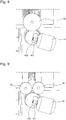
- the machining center 100 includes a plurality of machining stations 2. As visible on the figures 14 to 18 , each machining station 2 is in fact a non-permanent configuration, which results from a relative positioning of different stations 50 which face one another for a limited period which must allow the execution of the longest machining operation on the machining center 100, and which allows the realization of a particular type of machining in relation to a particular laying.
- machining is to be interpreted broadly, since it may include operations other than the traditional cutting and abrasion, and in particular laser machining or welding, bonding, crimping, or the like.
- Each machining station 2 is thus constituted by a temporary combination between stations 50, 51, 52, 53, 54, 501, 502, 503, 504, of two adjacent stages 10.
- the movement of a movable stage 10, in particular a rotation, is thus capable of modifying the relative positioning of the stations present, and substitutes, at the same geometrical location in space, a new machining station 2 for the previous one.
- the relative movement of the stages can allow, either to replace a machining station 2 according to a particular composition, another machining station of the same composition, or else to substitute a machining with another composition, the machining station 2 is then of variable composition: at least one relative movement between two indexing positions of two stages 10 is then able to modify the composition of each of the machining stations 2 to obtain at least two separate compositions from these machining stations 2.
- the machining center 2 it is possible to arrange the machining center 2 so as to mix these two modes of composition of the machining stations, so as to have, in a same production cycle, some machining stations identical to each other, and others that are different.
- cycle here is meant the path of a product to be machined on several successive machining stations 2, obtained by the rotation of at least one stage 10 relative to the base 60. Depending on the work to be performed, the complete machining may require a course of this product on all the machining stations 2 that can be formed, or only part. Certain machining stations 2 can be duplicated identically, in order to balance the transit time in each angular position, with the shortest possible duration.
- the product to be machined, assembled on a setting of the gripper 4, or on the gripper 4 itself is not necessarily unique: it can be a panoply of components.
- This panoply can include several identical components for the same operation, or several identical components but for different operations on the same machining station such as duplex machining, or even different components, the objective being to make the production of the machining center, while balancing the machining time on each work station 2. More particularly, each workpiece is loaded / pushed in a clamping, and all on a cleat which is indexed in the spindle.
- Each machining station 2 combines on the one hand at least one machining unit 3 of a station 50 of one of these adjacent floors 10, and on the other hand at least one gripper 4 of another station 50 on the other of the adjacent floors 10.
- each relative movement between two indexing positions of two stages 10 modifies the composition of each of the machining stations 2.
- This machining center 100 comprises, among the stages 10, at least a first stage 30 and a second stage 40 which are superimposed and adjacent, at least one of the first stage 30 and second stage 40 of which is movable relative to the 'fixed base 60.
- the first stage 30 and the second stage 40 are arranged so that, in any relative indexing position of the first stage 30 relative to the second stage 40, each machining station 2 formed in this indexing comprises at least one machining unit 3 belonging to one of these two stages 30 and 40 adjacent, and comprises at least one gripper 4 belonging to the other of these two stages 30 and 40 adjacent.
- each gripper 4 has at least one degree of freedom in rotation relative to the stage which carries it.
- each stage 10 comprising at least one gripper 4 has at least two degrees of freedom in rotation relative to the stage 10 which carries it. More particularly still, in each stage 10 comprising at least one gripper 4, each gripper 4 has at least two degrees of freedom in rotation relative to the stage 10 which carries it.
- At least the first stage 30 and the second stage 40 are each movable relative to the fixed base 60.
- This configuration makes it possible to reduce the return to no load at the end of the cycle, imposed by the various technical beams, as explained above, and in particular if these two stages move in opposite directions to one another.
- a first stage 30 and the second stage 40 can be extrapolated to a higher number of stages.
- the only real limitations are those due to the supply of technical fluids, and the supply of means specific to machining, in particular tools and lubricants.
- At least one station 50 comprises both at least one machining unit 3 and at least one gripper 4.
- at least one station of a adjacent and opposing stage also includes at least one machining unit 3 and at least one gripper 4, which allows unloading of a roughened part, for machining in recovery of the zone by which it was held in its initial gripper .
- At least one machining unit 3 is movable in position relative to the stage 10 which carries it. More particularly still, in at least one stage 10, each machining unit 3 is movable in position relative to the stage 10 which carries it. More particularly still, in any stage 10 comprising at least one machining unit 3, each machining unit 3 is movable in position relative to the stage 10 which carries it.
- At least one gripper 4 is movable in position relative to the stage 10 which carries it. More particularly still, in at least one stage 10, each gripper 4 is movable in position relative to the stage 10 which carries it. More particularly still, in any floor 10 comprising at least one gripper 4, each gripper 4 is movable in position relative to the stage 10 which carries it.
- At least one station 50 comprises several machining units 3, the races of which overlap, and the control means 90 are arranged to control each of them so as to avoid any collision with the others and the tools. they wear.
- One of these units 3 can thus continue a machining started by another unit 3 of the same station 50 during the execution of a cycle of tool change, or tool measurement, or diamond cutting, or other , of the machining unit 3 which has started the machining work; and the latter can resume machining work while the second unit in turn receives technical assistance.
- machining on the workpiece is not, or very little, interrupted during the presence of the gripper carrying this part facing this station 50 which carries several machining units 3.
- machining units 3 are independent of each other, and, more particularly, have separate guides.
- the machining center 100 advantageously comprises, among, or in addition to the machining stations 2, at least one automation station 6 for loading or unloading components to be machined or machined. More particularly, at least one such automation station 6 constitutes all or part of one of the stages 10. More particularly still, at least one such automation station 6 is a part, or all, of a mobile stage 10 relative to the fixed base 60.
- the figures illustrate stages all coaxial and mobile in rotation, substantially around the same vertical axis, relative to the fixed base 60, this particular case does not prevent other configurations where at least one of the stages is rotating around a horizontal axis, as are often the tool magazines of horizontal machining centers, it can be the configuration of the machining easements ; supply of parts, tools, part measurement, tool measurement, diamond dressing, and others.
- the machining center 100 can also have a complex structure of the “Rubik's cube” type with crossed rotational movements.
- control means 90 are arranged to control the stations 50 so as to pass successively each machining unit 3 and / or each gripper 4 in front of a fixed point in the vicinity of a fixed base 60 that the machining center 100, which can be the fixed base carrying the stages 10, or another base arranged laterally so as to clear the space around the work areas to allow monitoring by an operator.
- the machining center 100 comprises at least one diamond dressing station 8, which is arranged to proceed in masked time to diamond dressing of grinding wheels or tools carried by one of the machining 3. More particularly, the diamond dressing station 8 is distinct from the machining units 3.
- the machining center 100 includes at least one diamond tool machining station, which is arranged to diamond a workpiece held in a gripper 4.
- the machining center 100 comprises at least one tool changing station 9, which is arranged to proceed in masked time to the exchange of grinding wheels or tools carried by one of the machining units 3. More particularly , the tool changing station 9 is separate from the machining units 3. The tool changing station 9 is advantageously arranged to cooperate with a tool magazine 80, which comprises the machining center 100, and which may constitute one of the stages 10. More particularly, the tool changing station 9 is a stage 10 movable relative to the fixed base 60.
- At least one machining unit 3 comprises at least one stationary tool 341, and is arranged to cooperate with at least one gripper 4 of a stage adjacent to its own, which gripper 4 is movable according to at least one degree freedom with respect to the station 50 which carries it; it is thus possible to perform operations of turning, boring, whirling, or the like.
- At least one gripper 4 comprises at least one spindle 401 for driving a component to be machined at its machining speed.
- At least one gripper 4 comprises at least one clamp 402 for holding with clamping a component to be machined, to allow its machining, or its two-sided machining when the clamp is with jaws as on the figure 8 .
- At least one machining unit 3 comprises a plurality of spindles 301 suitable for machining the same component fixed on a gripper 4 with minimization of the tool change time.
- the machining center 100 comprises, in addition to the machining stations 2, at least one control station 11 for the geometric control of the machined components and / or of the tools used. More particularly, this control station 11 constitutes one of the stages 10. More particularly still, this control station 11 is a stage 10 movable relative to the fixed base 60.
- the control means 90 are preferably arranged to correct the trajectories and / or the dynamic tool correctors, and / or to manage tool replacements, or even to stop the machining cycle, as a function of the information coming from this control station 11.
- the machining center 100 comprises at least one lubrication and filtration unit capable of filtering the residues of at least one type of machining, in particular of rectification, diamond dressing, and satin finishing.
- the lubrication and filtration circuits can be separated, according to the lubricants to be used, in distinct geometrical zones: a circuit for machining with a cutting tool, another circuit for abrasive machining.
- the stages 10 which are movable relative to the fixed base 60 are movable in coaxial rotation around a single axis. More particularly, this single axis is vertical.
- the figures illustrate a particular, non-limiting variant, comprising four machining stations, each combining two zones 50, a first upper stage 30 static, and a second lower stage 40 dynamic.
- the machining center 100 comprises four stations: three reserved for machining, and a fourth machining designed for machining and / or for automation.
- the number of operational machining stations depends on the elementary cycle time, the breakdown of the overall cycle time, and the handling time of the part.
- a machining unit 3 can comprise one or more degrees of freedom in rotation, as a gripper 4 can also include one or more degrees of freedom in translation.
- Some of these additional degrees of freedom, in particular in translation, can be semi-axes, to carry out a palletization in abutment on extreme positions without stopping on intermediate positions, or a rotation of a plate between indexed positions without stopping on intermediate positions.
- the entire second stage 40 comprising the dividers is indexed, from station to station.
- This compactness allows short force loops, and allows to have rigid structural parts, combined with kinematics easy to protect.
- an even number of layings allows a machining concept according to which where the six faces of the piece in recovery are worked (for example twice on a first laying on face A, twice on a second laying on side B), making two passes through the machine.
- the machine also allows an application for the machining of horological blanks, with the possibility of turning the workpiece using the C axis to machine the two faces in a single clamping, as well as the machining on the edge, and with the possibility of hiding the tool change time with the double-spindle principle.
- the application to grinding can be done with a single grinding wheel, for example of diameter 300mm, or else with several smaller grinding wheels, for example two grinding wheels of diameter 200mm.
- the machine remains versatile enough to allow other types of machining than those for which the machine is designed.
- the machining center 100 is more particularly designed for work from a stock, or in recovery.
- at least one stage 10 carrying machining units 3 may be provided with a bar feeder, or else with a mini-bar feeder, of length close to that of the spindle, at a level of these machining units 3, which supposes that the corresponding machining unit 3 is fixed.
- this bar feeder is unique because, if it is theoretically possible to set up several machining units 3 with such feed by bar feeder, the footprint is then greatly increased, which reduces one of the advantages of this machine, which is its compactness. More particularly, this bar feeder is fixed to the base 60.
- the advantage of a machining center as described and illustrated is the complete machining of finished components, without rework.
- this machining is carried out in a single clamping, with work only on five sides.
- this machining is carried out with part turning, and change of clamping, for machining on the whole of this component, on all its faces.
- the machining center according to the invention allows very short operating times.
- the cycle of supply of crude to be machined and of unloading of the machined components is far from being negligible compared to the machining times on each of the work stations 2, and in front of the time of the complete cycle, and this duration of charge / discharge can in certain cases constitute the time leading from the global cycle.
- the invention makes it possible to increase performance in different watchmaking applications, while making it possible to standardize production equipment. In addition, thanks to its relatively modest number of stations, this machine is more suited to current watch production batches than to large series of yesteryear.
Landscapes
- Engineering & Computer Science (AREA)
- Mechanical Engineering (AREA)
- Physics & Mathematics (AREA)
- General Physics & Mathematics (AREA)
- Optics & Photonics (AREA)
- Machine Tool Units (AREA)
Priority Applications (4)
| Application Number | Priority Date | Filing Date | Title |
|---|---|---|---|
| EP18195543.6A EP3626392B1 (de) | 2018-09-19 | 2018-09-19 | Bearbeitungszentrum für uhrenkomponenten |
| US16/543,805 US11524381B2 (en) | 2018-09-19 | 2019-08-19 | Machining centre for timepiece components |
| JP2019157717A JP6936285B2 (ja) | 2018-09-19 | 2019-08-30 | 計時器用部品のためのマシニングセンター |
| CN201910885132.XA CN110919372B (zh) | 2018-09-19 | 2019-09-19 | 用于钟表部件的加工中心 |
Applications Claiming Priority (1)
| Application Number | Priority Date | Filing Date | Title |
|---|---|---|---|
| EP18195543.6A EP3626392B1 (de) | 2018-09-19 | 2018-09-19 | Bearbeitungszentrum für uhrenkomponenten |
Publications (2)
| Publication Number | Publication Date |
|---|---|
| EP3626392A1 true EP3626392A1 (de) | 2020-03-25 |
| EP3626392B1 EP3626392B1 (de) | 2021-07-28 |
Family
ID=63642897
Family Applications (1)
| Application Number | Title | Priority Date | Filing Date |
|---|---|---|---|
| EP18195543.6A Active EP3626392B1 (de) | 2018-09-19 | 2018-09-19 | Bearbeitungszentrum für uhrenkomponenten |
Country Status (4)
| Country | Link |
|---|---|
| US (1) | US11524381B2 (de) |
| EP (1) | EP3626392B1 (de) |
| JP (1) | JP6936285B2 (de) |
| CN (1) | CN110919372B (de) |
Families Citing this family (4)
| Publication number | Priority date | Publication date | Assignee | Title |
|---|---|---|---|---|
| EP3797733A1 (de) * | 2019-09-24 | 2021-03-31 | DENTSPLY SIRONA Inc. | Verfahren zur planung von freiformwerkzeugbahnen zur gleichzeitigen beidseitigen bearbeitung mit kinematischer achsenkopplung |
| IT202100007280A1 (it) * | 2021-03-25 | 2022-09-25 | Dan Di De Antoni S R L | Apparecchiatura per la lavorazione superficiale di pezzi |
| EP4082718B1 (de) * | 2021-04-26 | 2025-02-19 | ETA SA Manufacture Horlogère Suisse | Aufnahmevorrichtung für uhr |
| CN120587962B (zh) * | 2025-08-07 | 2025-10-28 | 云南精机琥正机械有限公司 | 双工位立车车床智能一体化上下料集成装置 |
Citations (5)
| Publication number | Priority date | Publication date | Assignee | Title |
|---|---|---|---|---|
| JPS5682149A (en) * | 1980-11-21 | 1981-07-04 | Hitachi Seiki Co Ltd | Collecting apparatus of waste for machine module |
| EP2306253A1 (de) * | 2008-07-10 | 2011-04-06 | Citizen Machinery Co., Ltd. | Kollisionsprüfgerät, kollisionsprüfverfahren und werkzeugmaschine mit dem interferenzprüfgerät |
| CH706794B1 (de) * | 2013-01-11 | 2014-02-14 | Bumotec Sa | Bearbeitungseinheit mit zwei Arbeitsspindeln. |
| US20160346888A1 (en) * | 2014-01-23 | 2016-12-01 | Martin Huber | Machining Device for Machine-Assisted Production and Machining of Dental Workpieces |
| WO2017182839A1 (en) * | 2016-04-18 | 2017-10-26 | Metotecna Sagl | Transfer machine with a rotary table |
Family Cites Families (32)
| Publication number | Priority date | Publication date | Assignee | Title |
|---|---|---|---|---|
| US1360175A (en) * | 1917-10-25 | 1920-11-23 | Bullard Machine Tool Co | Multiple-spindle machine-tool |
| US1508974A (en) * | 1921-07-30 | 1924-09-16 | Reading Automatic Machine Comp | Automatic multiple-spindle-machine tool |
| US1804971A (en) * | 1925-05-02 | 1931-05-12 | Bullard Co | Multiple spindle center turning machine |
| US1911303A (en) * | 1930-11-08 | 1933-05-30 | Jr John Wilson Brown | Bossed arm drilling machine |
| US1967689A (en) * | 1930-12-16 | 1934-07-24 | Cincinnati Bickford Tool Co | Cam controlled multispindle machine |
| US2182799A (en) * | 1938-05-28 | 1939-12-12 | Budd Wheel Co | Heat treating machine tool |
| US2358389A (en) * | 1940-08-04 | 1944-09-19 | Carter Carburetor Corp | Indexing type multiple station drilling machine |
| US2628413A (en) * | 1947-05-16 | 1953-02-17 | Baker Bros Inc | Turret control mechanism |
| US3203316A (en) * | 1963-04-30 | 1965-08-31 | Saginaw Machine And Tool Compa | Machine tool construction |
| US3792633A (en) * | 1973-04-02 | 1974-02-19 | V Kogtev | Vertical multispindle continuous lathe |
| US4642861A (en) * | 1983-09-12 | 1987-02-17 | Saginaw Machine Systems, Inc. | Machine tool construction |
| CH671723A5 (de) * | 1988-03-08 | 1989-09-29 | Azypatent Ag | |
| JPH0755417B2 (ja) * | 1989-12-21 | 1995-06-14 | 南精工株式会社 | 鋳型の加工機 |
| JP2678838B2 (ja) * | 1991-07-24 | 1997-11-19 | オークマ株式会社 | 複合加工nc旋盤 |
| JPH05147062A (ja) | 1991-11-28 | 1993-06-15 | Yamada Seisakusho Co Ltd | トランスフアモールド装置 |
| JP3961214B2 (ja) | 2000-11-24 | 2007-08-22 | オークマ株式会社 | 複合加工機 |
| DE10153807A1 (de) * | 2001-11-05 | 2003-05-28 | Emag Maschfab Gmbh | Werkzeugmaschine |
| JP2004174627A (ja) | 2002-11-25 | 2004-06-24 | Matsushita Refrigeration Industries (S) Pte Ltd | 切削研削方法とその装置 |
| EP1557729B1 (de) | 2004-01-26 | 2008-04-23 | Nivarox-FAR S.A. | Herstellungsverfahren für Zeitindexen und Apparat für seine Implementierung |
| JP4624030B2 (ja) | 2004-08-05 | 2011-02-02 | 株式会社岡本工作機械製作所 | 金属工作機械の機枠およびその鋳造方法 |
| EP1775050A1 (de) | 2005-10-14 | 2007-04-18 | Eric Bouille | Anordnung aus Uhrengehäusen |
| JP2009297861A (ja) * | 2008-06-16 | 2009-12-24 | Makino J Kk | 機械加工システム |
| CN201464830U (zh) | 2009-03-26 | 2010-05-12 | 上海大学 | 多功能小型精密钟表机床 |
| JP5456500B2 (ja) | 2010-02-01 | 2014-03-26 | 小島プレス工業株式会社 | 加工装置 |
| JP6059947B2 (ja) | 2012-10-24 | 2017-01-11 | Dmg森精機株式会社 | 複合加工機及び加工方法 |
| DE102014100212B4 (de) | 2013-01-11 | 2018-04-05 | Bumotec Sa | Bearbeitungseinheit mit zwei Arbeitsspindeln und Fertigungsstraße |
| IN2013MU04099A (de) * | 2013-12-30 | 2015-08-07 | N Kelkar Nitin | |
| JP5799119B2 (ja) | 2014-02-07 | 2015-10-21 | 本田技研工業株式会社 | 軸物ワークの加工装置 |
| CN204094461U (zh) * | 2014-08-06 | 2015-01-14 | 烟台环球机床装备股份有限公司 | 一种组合机床 |
| DE102015009017A1 (de) | 2015-07-10 | 2017-01-12 | Liebherr-Verzahntechnik Gmbh | Verfahren zur Herstellung eines verzahnten Werkstückes mit modifizierter Oberflächengeometrie |
| WO2017054130A1 (en) | 2015-09-29 | 2017-04-06 | Abb Schweiz Ag | Method and system for machining |
| CN107193203B (zh) | 2017-04-20 | 2020-01-07 | 浙江卓越电子有限公司 | 一种电子手表表带自动钻冲孔机及使用方法 |
-
2018
- 2018-09-19 EP EP18195543.6A patent/EP3626392B1/de active Active
-
2019
- 2019-08-19 US US16/543,805 patent/US11524381B2/en active Active
- 2019-08-30 JP JP2019157717A patent/JP6936285B2/ja active Active
- 2019-09-19 CN CN201910885132.XA patent/CN110919372B/zh active Active
Patent Citations (5)
| Publication number | Priority date | Publication date | Assignee | Title |
|---|---|---|---|---|
| JPS5682149A (en) * | 1980-11-21 | 1981-07-04 | Hitachi Seiki Co Ltd | Collecting apparatus of waste for machine module |
| EP2306253A1 (de) * | 2008-07-10 | 2011-04-06 | Citizen Machinery Co., Ltd. | Kollisionsprüfgerät, kollisionsprüfverfahren und werkzeugmaschine mit dem interferenzprüfgerät |
| CH706794B1 (de) * | 2013-01-11 | 2014-02-14 | Bumotec Sa | Bearbeitungseinheit mit zwei Arbeitsspindeln. |
| US20160346888A1 (en) * | 2014-01-23 | 2016-12-01 | Martin Huber | Machining Device for Machine-Assisted Production and Machining of Dental Workpieces |
| WO2017182839A1 (en) * | 2016-04-18 | 2017-10-26 | Metotecna Sagl | Transfer machine with a rotary table |
Also Published As
| Publication number | Publication date |
|---|---|
| JP2020044646A (ja) | 2020-03-26 |
| CN110919372A (zh) | 2020-03-27 |
| US11524381B2 (en) | 2022-12-13 |
| JP6936285B2 (ja) | 2021-09-15 |
| US20200086447A1 (en) | 2020-03-19 |
| CN110919372B (zh) | 2021-11-09 |
| EP3626392B1 (de) | 2021-07-28 |
Similar Documents
| Publication | Publication Date | Title |
|---|---|---|
| EP3626392B1 (de) | Bearbeitungszentrum für uhrenkomponenten | |
| FR2563454A1 (fr) | Machine-outil multi-fonctions a deux broches | |
| EP1314512B1 (de) | Greifeinheit für die automatisierte Bearbeitung von Werkstücken, und Vorrichtung und Verfahren mit einer solchen Einheit | |
| EP0799104A1 (de) | Werkzeugmaschine zum bearbeiten von kurbewellen für vierzylinder in-line motoren, methode zum verwenden dessen, und maschinlinie in denen diese maschine verwendet wird | |
| US11045879B2 (en) | Turning machine and method for turning workpieces | |
| LU82096A1 (fr) | Perfectionnements aux machines-outils du type centre d'usinage | |
| FR2983104A1 (fr) | Dispositif et procede de meulage d'un filetage exterieur a billes | |
| FR3057482B1 (fr) | Installation et procede d’assemblage d’elements de carrosserie avec changement d’outil par rotonde | |
| CH715355A2 (fr) | Centre d'usinage pour composants d'horlogerie. | |
| FR2641998A1 (fr) | Procede pour l'usinage de pieces au moyen de centres d'usinage a commande numerique, et centre d'usinage pour la mise en oeuvre de ce procede | |
| FR2833198A1 (fr) | Dispositif pour le traitement de surfaces mecanique de pieces usinees | |
| EP1457290A1 (de) | Aufspannvorrichtung zum polieren, förderschale, förderverfahren und fördervorrichtung | |
| FR2534837A1 (fr) | Plateau diviseur destine a assurer la tenue d'une piece lors de son usinage | |
| FR2809649A1 (fr) | Systeme de rotation du plateau de machines de transfert | |
| FR2806952A1 (fr) | Poste de travail de type perfectionne | |
| EP0638007B1 (de) | Mehrspindeldrehautomat | |
| JP2007175852A (ja) | 逆立ち主軸複合nc旋盤 | |
| CN116600935A (zh) | 用于批量生产高精度工件的机床方案 | |
| FR2976199A1 (fr) | Agencement de presses disposees les unes a la suite des autres pour le travail de pieces en tole et presse implantee dans un tel agencement | |
| FR2612052A1 (fr) | Installation pour la fabrication automatisee des chaussures | |
| JP6499560B2 (ja) | ワークの搬出装置 | |
| FR2763873A1 (fr) | Centre d'usinage 5 axes a tres grande vitesse pour pieces de tres grandes dimensions | |
| JP5901415B2 (ja) | 研削盤ラインおよび研削盤ライン生産システム | |
| FR2492292A1 (fr) | Tour a decolleter perfectionne | |
| CH586094A5 (en) | Light grinding or milling machine with automatic loading - has twin heads with headstock alternating between them as loading arm operates |
Legal Events
| Date | Code | Title | Description |
|---|---|---|---|
| PUAI | Public reference made under article 153(3) epc to a published international application that has entered the european phase |
Free format text: ORIGINAL CODE: 0009012 |
|
| STAA | Information on the status of an ep patent application or granted ep patent |
Free format text: STATUS: THE APPLICATION HAS BEEN PUBLISHED |
|
| AK | Designated contracting states |
Kind code of ref document: A1 Designated state(s): AL AT BE BG CH CY CZ DE DK EE ES FI FR GB GR HR HU IE IS IT LI LT LU LV MC MK MT NL NO PL PT RO RS SE SI SK SM TR |
|
| AX | Request for extension of the european patent |
Extension state: BA ME |
|
| STAA | Information on the status of an ep patent application or granted ep patent |
Free format text: STATUS: REQUEST FOR EXAMINATION WAS MADE |
|
| 17P | Request for examination filed |
Effective date: 20200925 |
|
| RBV | Designated contracting states (corrected) |
Designated state(s): AL AT BE BG CH CY CZ DE DK EE ES FI FR GB GR HR HU IE IS IT LI LT LU LV MC MK MT NL NO PL PT RO RS SE SI SK SM TR |
|
| GRAP | Despatch of communication of intention to grant a patent |
Free format text: ORIGINAL CODE: EPIDOSNIGR1 |
|
| STAA | Information on the status of an ep patent application or granted ep patent |
Free format text: STATUS: GRANT OF PATENT IS INTENDED |
|
| RIC1 | Information provided on ipc code assigned before grant |
Ipc: B23Q 39/02 20060101AFI20210212BHEP Ipc: B23Q 39/04 20060101ALI20210212BHEP |
|
| INTG | Intention to grant announced |
Effective date: 20210319 |
|
| GRAS | Grant fee paid |
Free format text: ORIGINAL CODE: EPIDOSNIGR3 |
|
| GRAA | (expected) grant |
Free format text: ORIGINAL CODE: 0009210 |
|
| STAA | Information on the status of an ep patent application or granted ep patent |
Free format text: STATUS: THE PATENT HAS BEEN GRANTED |
|
| AK | Designated contracting states |
Kind code of ref document: B1 Designated state(s): AL AT BE BG CH CY CZ DE DK EE ES FI FR GB GR HR HU IE IS IT LI LT LU LV MC MK MT NL NO PL PT RO RS SE SI SK SM TR |
|
| REG | Reference to a national code |
Ref country code: GB Ref legal event code: FG4D Free format text: NOT ENGLISH |
|
| REG | Reference to a national code |
Ref country code: CH Ref legal event code: EP |
|
| REG | Reference to a national code |
Ref country code: DE Ref legal event code: R096 Ref document number: 602018020702 Country of ref document: DE |
|
| REG | Reference to a national code |
Ref country code: AT Ref legal event code: REF Ref document number: 1414287 Country of ref document: AT Kind code of ref document: T Effective date: 20210815 |
|
| REG | Reference to a national code |
Ref country code: IE Ref legal event code: FG4D Free format text: LANGUAGE OF EP DOCUMENT: FRENCH |
|
| REG | Reference to a national code |
Ref country code: LT Ref legal event code: MG9D |
|
| REG | Reference to a national code |
Ref country code: NL Ref legal event code: MP Effective date: 20210728 |
|
| REG | Reference to a national code |
Ref country code: AT Ref legal event code: MK05 Ref document number: 1414287 Country of ref document: AT Kind code of ref document: T Effective date: 20210728 |
|
| PG25 | Lapsed in a contracting state [announced via postgrant information from national office to epo] |
Ref country code: FI Free format text: LAPSE BECAUSE OF FAILURE TO SUBMIT A TRANSLATION OF THE DESCRIPTION OR TO PAY THE FEE WITHIN THE PRESCRIBED TIME-LIMIT Effective date: 20210728 Ref country code: ES Free format text: LAPSE BECAUSE OF FAILURE TO SUBMIT A TRANSLATION OF THE DESCRIPTION OR TO PAY THE FEE WITHIN THE PRESCRIBED TIME-LIMIT Effective date: 20210728 Ref country code: HR Free format text: LAPSE BECAUSE OF FAILURE TO SUBMIT A TRANSLATION OF THE DESCRIPTION OR TO PAY THE FEE WITHIN THE PRESCRIBED TIME-LIMIT Effective date: 20210728 Ref country code: SE Free format text: LAPSE BECAUSE OF FAILURE TO SUBMIT A TRANSLATION OF THE DESCRIPTION OR TO PAY THE FEE WITHIN THE PRESCRIBED TIME-LIMIT Effective date: 20210728 Ref country code: RS Free format text: LAPSE BECAUSE OF FAILURE TO SUBMIT A TRANSLATION OF THE DESCRIPTION OR TO PAY THE FEE WITHIN THE PRESCRIBED TIME-LIMIT Effective date: 20210728 Ref country code: BG Free format text: LAPSE BECAUSE OF FAILURE TO SUBMIT A TRANSLATION OF THE DESCRIPTION OR TO PAY THE FEE WITHIN THE PRESCRIBED TIME-LIMIT Effective date: 20211028 Ref country code: AT Free format text: LAPSE BECAUSE OF FAILURE TO SUBMIT A TRANSLATION OF THE DESCRIPTION OR TO PAY THE FEE WITHIN THE PRESCRIBED TIME-LIMIT Effective date: 20210728 Ref country code: LT Free format text: LAPSE BECAUSE OF FAILURE TO SUBMIT A TRANSLATION OF THE DESCRIPTION OR TO PAY THE FEE WITHIN THE PRESCRIBED TIME-LIMIT Effective date: 20210728 Ref country code: NL Free format text: LAPSE BECAUSE OF FAILURE TO SUBMIT A TRANSLATION OF THE DESCRIPTION OR TO PAY THE FEE WITHIN THE PRESCRIBED TIME-LIMIT Effective date: 20210728 Ref country code: PT Free format text: LAPSE BECAUSE OF FAILURE TO SUBMIT A TRANSLATION OF THE DESCRIPTION OR TO PAY THE FEE WITHIN THE PRESCRIBED TIME-LIMIT Effective date: 20211129 Ref country code: NO Free format text: LAPSE BECAUSE OF FAILURE TO SUBMIT A TRANSLATION OF THE DESCRIPTION OR TO PAY THE FEE WITHIN THE PRESCRIBED TIME-LIMIT Effective date: 20211028 |
|
| PG25 | Lapsed in a contracting state [announced via postgrant information from national office to epo] |
Ref country code: PL Free format text: LAPSE BECAUSE OF FAILURE TO SUBMIT A TRANSLATION OF THE DESCRIPTION OR TO PAY THE FEE WITHIN THE PRESCRIBED TIME-LIMIT Effective date: 20210728 Ref country code: LV Free format text: LAPSE BECAUSE OF FAILURE TO SUBMIT A TRANSLATION OF THE DESCRIPTION OR TO PAY THE FEE WITHIN THE PRESCRIBED TIME-LIMIT Effective date: 20210728 Ref country code: GR Free format text: LAPSE BECAUSE OF FAILURE TO SUBMIT A TRANSLATION OF THE DESCRIPTION OR TO PAY THE FEE WITHIN THE PRESCRIBED TIME-LIMIT Effective date: 20211029 |
|
| PG25 | Lapsed in a contracting state [announced via postgrant information from national office to epo] |
Ref country code: DK Free format text: LAPSE BECAUSE OF FAILURE TO SUBMIT A TRANSLATION OF THE DESCRIPTION OR TO PAY THE FEE WITHIN THE PRESCRIBED TIME-LIMIT Effective date: 20210728 |
|
| REG | Reference to a national code |
Ref country code: DE Ref legal event code: R097 Ref document number: 602018020702 Country of ref document: DE |
|
| REG | Reference to a national code |
Ref country code: BE Ref legal event code: MM Effective date: 20210930 |
|
| PG25 | Lapsed in a contracting state [announced via postgrant information from national office to epo] |
Ref country code: SM Free format text: LAPSE BECAUSE OF FAILURE TO SUBMIT A TRANSLATION OF THE DESCRIPTION OR TO PAY THE FEE WITHIN THE PRESCRIBED TIME-LIMIT Effective date: 20210728 Ref country code: SK Free format text: LAPSE BECAUSE OF FAILURE TO SUBMIT A TRANSLATION OF THE DESCRIPTION OR TO PAY THE FEE WITHIN THE PRESCRIBED TIME-LIMIT Effective date: 20210728 Ref country code: RO Free format text: LAPSE BECAUSE OF FAILURE TO SUBMIT A TRANSLATION OF THE DESCRIPTION OR TO PAY THE FEE WITHIN THE PRESCRIBED TIME-LIMIT Effective date: 20210728 Ref country code: MC Free format text: LAPSE BECAUSE OF FAILURE TO SUBMIT A TRANSLATION OF THE DESCRIPTION OR TO PAY THE FEE WITHIN THE PRESCRIBED TIME-LIMIT Effective date: 20210728 Ref country code: EE Free format text: LAPSE BECAUSE OF FAILURE TO SUBMIT A TRANSLATION OF THE DESCRIPTION OR TO PAY THE FEE WITHIN THE PRESCRIBED TIME-LIMIT Effective date: 20210728 Ref country code: CZ Free format text: LAPSE BECAUSE OF FAILURE TO SUBMIT A TRANSLATION OF THE DESCRIPTION OR TO PAY THE FEE WITHIN THE PRESCRIBED TIME-LIMIT Effective date: 20210728 Ref country code: AL Free format text: LAPSE BECAUSE OF FAILURE TO SUBMIT A TRANSLATION OF THE DESCRIPTION OR TO PAY THE FEE WITHIN THE PRESCRIBED TIME-LIMIT Effective date: 20210728 |
|
| PLBE | No opposition filed within time limit |
Free format text: ORIGINAL CODE: 0009261 |
|
| STAA | Information on the status of an ep patent application or granted ep patent |
Free format text: STATUS: NO OPPOSITION FILED WITHIN TIME LIMIT |
|
| 26N | No opposition filed |
Effective date: 20220429 |
|
| PG25 | Lapsed in a contracting state [announced via postgrant information from national office to epo] |
Ref country code: LU Free format text: LAPSE BECAUSE OF NON-PAYMENT OF DUE FEES Effective date: 20210919 Ref country code: IT Free format text: LAPSE BECAUSE OF FAILURE TO SUBMIT A TRANSLATION OF THE DESCRIPTION OR TO PAY THE FEE WITHIN THE PRESCRIBED TIME-LIMIT Effective date: 20210728 Ref country code: IE Free format text: LAPSE BECAUSE OF NON-PAYMENT OF DUE FEES Effective date: 20210919 Ref country code: BE Free format text: LAPSE BECAUSE OF NON-PAYMENT OF DUE FEES Effective date: 20210930 |
|
| PG25 | Lapsed in a contracting state [announced via postgrant information from national office to epo] |
Ref country code: CY Free format text: LAPSE BECAUSE OF FAILURE TO SUBMIT A TRANSLATION OF THE DESCRIPTION OR TO PAY THE FEE WITHIN THE PRESCRIBED TIME-LIMIT Effective date: 20210728 |
|
| PG25 | Lapsed in a contracting state [announced via postgrant information from national office to epo] |
Ref country code: HU Free format text: LAPSE BECAUSE OF FAILURE TO SUBMIT A TRANSLATION OF THE DESCRIPTION OR TO PAY THE FEE WITHIN THE PRESCRIBED TIME-LIMIT; INVALID AB INITIO Effective date: 20180919 |
|
| P01 | Opt-out of the competence of the unified patent court (upc) registered |
Effective date: 20230701 |
|
| PG25 | Lapsed in a contracting state [announced via postgrant information from national office to epo] |
Ref country code: MK Free format text: LAPSE BECAUSE OF FAILURE TO SUBMIT A TRANSLATION OF THE DESCRIPTION OR TO PAY THE FEE WITHIN THE PRESCRIBED TIME-LIMIT Effective date: 20210728 |
|
| PG25 | Lapsed in a contracting state [announced via postgrant information from national office to epo] |
Ref country code: MT Free format text: LAPSE BECAUSE OF FAILURE TO SUBMIT A TRANSLATION OF THE DESCRIPTION OR TO PAY THE FEE WITHIN THE PRESCRIBED TIME-LIMIT Effective date: 20210728 |
|
| REG | Reference to a national code |
Ref country code: CH Ref legal event code: U11 Free format text: ST27 STATUS EVENT CODE: U-0-0-U10-U11 (AS PROVIDED BY THE NATIONAL OFFICE) Effective date: 20251001 |
|
| PGFP | Annual fee paid to national office [announced via postgrant information from national office to epo] |
Ref country code: DE Payment date: 20250820 Year of fee payment: 8 |
|
| PGFP | Annual fee paid to national office [announced via postgrant information from national office to epo] |
Ref country code: GB Payment date: 20250822 Year of fee payment: 8 |
|
| PGFP | Annual fee paid to national office [announced via postgrant information from national office to epo] |
Ref country code: FR Payment date: 20250820 Year of fee payment: 8 |
|
| PG25 | Lapsed in a contracting state [announced via postgrant information from national office to epo] |
Ref country code: TR Free format text: LAPSE BECAUSE OF FAILURE TO SUBMIT A TRANSLATION OF THE DESCRIPTION OR TO PAY THE FEE WITHIN THE PRESCRIBED TIME-LIMIT Effective date: 20210728 |
|
| PGFP | Annual fee paid to national office [announced via postgrant information from national office to epo] |
Ref country code: CH Payment date: 20251001 Year of fee payment: 8 |