EP3626501A1 - Structure de transmission à dérivation de puissance - Google Patents
Structure de transmission à dérivation de puissance Download PDFInfo
- Publication number
- EP3626501A1 EP3626501A1 EP19196874.2A EP19196874A EP3626501A1 EP 3626501 A1 EP3626501 A1 EP 3626501A1 EP 19196874 A EP19196874 A EP 19196874A EP 3626501 A1 EP3626501 A1 EP 3626501A1
- Authority
- EP
- European Patent Office
- Prior art keywords
- power
- transmission structure
- output
- electrical
- drive
- Prior art date
- Legal status (The legal status is an assumption and is not a legal conclusion. Google has not performed a legal analysis and makes no representation as to the accuracy of the status listed.)
- Withdrawn
Links
- 230000005540 biological transmission Effects 0.000 claims abstract description 71
- 230000001105 regulatory effect Effects 0.000 claims abstract description 3
- 238000000034 method Methods 0.000 claims description 6
- 230000001276 controlling effect Effects 0.000 claims description 4
- 238000011161 development Methods 0.000 description 5
- 238000010276 construction Methods 0.000 description 4
- 238000006243 chemical reaction Methods 0.000 description 2
- 238000002485 combustion reaction Methods 0.000 description 2
- 230000002706 hydrostatic effect Effects 0.000 description 2
- 230000033228 biological regulation Effects 0.000 description 1
- 230000007423 decrease Effects 0.000 description 1
- 238000013461 design Methods 0.000 description 1
- 238000012423 maintenance Methods 0.000 description 1
- 230000002123 temporal effect Effects 0.000 description 1
- 238000012546 transfer Methods 0.000 description 1
Images

Classifications
-
- B—PERFORMING OPERATIONS; TRANSPORTING
- B60—VEHICLES IN GENERAL
- B60K—ARRANGEMENT OR MOUNTING OF PROPULSION UNITS OR OF TRANSMISSIONS IN VEHICLES; ARRANGEMENT OR MOUNTING OF PLURAL DIVERSE PRIME-MOVERS IN VEHICLES; AUXILIARY DRIVES FOR VEHICLES; INSTRUMENTATION OR DASHBOARDS FOR VEHICLES; ARRANGEMENTS IN CONNECTION WITH COOLING, AIR INTAKE, GAS EXHAUST OR FUEL SUPPLY OF PROPULSION UNITS IN VEHICLES
- B60K17/00—Arrangement or mounting of transmissions in vehicles
- B60K17/28—Arrangement or mounting of transmissions in vehicles characterised by arrangement, location, or type of power take-off
-
- F—MECHANICAL ENGINEERING; LIGHTING; HEATING; WEAPONS; BLASTING
- F16—ENGINEERING ELEMENTS AND UNITS; GENERAL MEASURES FOR PRODUCING AND MAINTAINING EFFECTIVE FUNCTIONING OF MACHINES OR INSTALLATIONS; THERMAL INSULATION IN GENERAL
- F16H—GEARING
- F16H37/00—Combinations of mechanical gearings, not provided for in groups F16H1/00 - F16H35/00
- F16H37/02—Combinations of mechanical gearings, not provided for in groups F16H1/00 - F16H35/00 comprising essentially only toothed or friction gearings
- F16H37/04—Combinations of toothed gearings only
- F16H37/042—Combinations of toothed gearings only change gear transmissions in group arrangement
-
- B—PERFORMING OPERATIONS; TRANSPORTING
- B60—VEHICLES IN GENERAL
- B60K—ARRANGEMENT OR MOUNTING OF PROPULSION UNITS OR OF TRANSMISSIONS IN VEHICLES; ARRANGEMENT OR MOUNTING OF PLURAL DIVERSE PRIME-MOVERS IN VEHICLES; AUXILIARY DRIVES FOR VEHICLES; INSTRUMENTATION OR DASHBOARDS FOR VEHICLES; ARRANGEMENTS IN CONNECTION WITH COOLING, AIR INTAKE, GAS EXHAUST OR FUEL SUPPLY OF PROPULSION UNITS IN VEHICLES
- B60K25/00—Auxiliary drives
- B60K25/06—Auxiliary drives from the transmission power take-off
-
- F—MECHANICAL ENGINEERING; LIGHTING; HEATING; WEAPONS; BLASTING
- F16—ENGINEERING ELEMENTS AND UNITS; GENERAL MEASURES FOR PRODUCING AND MAINTAINING EFFECTIVE FUNCTIONING OF MACHINES OR INSTALLATIONS; THERMAL INSULATION IN GENERAL
- F16H—GEARING
- F16H61/00—Control functions within control units of change-speed- or reversing-gearings for conveying rotary motion ; Control of exclusively fluid gearing, friction gearing, gearings with endless flexible members or other particular types of gearing
- F16H61/66—Control functions within control units of change-speed- or reversing-gearings for conveying rotary motion ; Control of exclusively fluid gearing, friction gearing, gearings with endless flexible members or other particular types of gearing specially adapted for continuously variable gearings
- F16H61/664—Friction gearings
-
- F—MECHANICAL ENGINEERING; LIGHTING; HEATING; WEAPONS; BLASTING
- F16—ENGINEERING ELEMENTS AND UNITS; GENERAL MEASURES FOR PRODUCING AND MAINTAINING EFFECTIVE FUNCTIONING OF MACHINES OR INSTALLATIONS; THERMAL INSULATION IN GENERAL
- F16H—GEARING
- F16H63/00—Control outputs from the control unit to change-speed- or reversing-gearings for conveying rotary motion or to other devices than the final output mechanism
- F16H63/02—Final output mechanisms therefor; Actuating means for the final output mechanisms
- F16H63/08—Multiple final output mechanisms being moved by a single common final actuating mechanism
-
- B—PERFORMING OPERATIONS; TRANSPORTING
- B60—VEHICLES IN GENERAL
- B60K—ARRANGEMENT OR MOUNTING OF PROPULSION UNITS OR OF TRANSMISSIONS IN VEHICLES; ARRANGEMENT OR MOUNTING OF PLURAL DIVERSE PRIME-MOVERS IN VEHICLES; AUXILIARY DRIVES FOR VEHICLES; INSTRUMENTATION OR DASHBOARDS FOR VEHICLES; ARRANGEMENTS IN CONNECTION WITH COOLING, AIR INTAKE, GAS EXHAUST OR FUEL SUPPLY OF PROPULSION UNITS IN VEHICLES
- B60K25/00—Auxiliary drives
- B60K25/06—Auxiliary drives from the transmission power take-off
- B60K2025/065—Auxiliary drives from the transmission power take-off the transmission being fluidic, e.g. hydraulic
-
- F—MECHANICAL ENGINEERING; LIGHTING; HEATING; WEAPONS; BLASTING
- F16—ENGINEERING ELEMENTS AND UNITS; GENERAL MEASURES FOR PRODUCING AND MAINTAINING EFFECTIVE FUNCTIONING OF MACHINES OR INSTALLATIONS; THERMAL INSULATION IN GENERAL
- F16H—GEARING
- F16H37/00—Combinations of mechanical gearings, not provided for in groups F16H1/00 - F16H35/00
- F16H37/02—Combinations of mechanical gearings, not provided for in groups F16H1/00 - F16H35/00 comprising essentially only toothed or friction gearings
- F16H37/04—Combinations of toothed gearings only
- F16H2037/048—Combinations of parallel shaft and orbital motion gearing, wherein the orbital motion gearing has more than one connection with the parallel shaft gearing
-
- F—MECHANICAL ENGINEERING; LIGHTING; HEATING; WEAPONS; BLASTING
- F16—ENGINEERING ELEMENTS AND UNITS; GENERAL MEASURES FOR PRODUCING AND MAINTAINING EFFECTIVE FUNCTIONING OF MACHINES OR INSTALLATIONS; THERMAL INSULATION IN GENERAL
- F16H—GEARING
- F16H61/00—Control functions within control units of change-speed- or reversing-gearings for conveying rotary motion ; Control of exclusively fluid gearing, friction gearing, gearings with endless flexible members or other particular types of gearing
- F16H2061/0012—Transmission control for optimising power output of driveline
-
- F—MECHANICAL ENGINEERING; LIGHTING; HEATING; WEAPONS; BLASTING
- F16—ENGINEERING ELEMENTS AND UNITS; GENERAL MEASURES FOR PRODUCING AND MAINTAINING EFFECTIVE FUNCTIONING OF MACHINES OR INSTALLATIONS; THERMAL INSULATION IN GENERAL
- F16H—GEARING
- F16H2200/00—Transmissions for multiple ratios
- F16H2200/20—Transmissions using gears with orbital motion
- F16H2200/2002—Transmissions using gears with orbital motion characterised by the number of sets of orbital gears
- F16H2200/2007—Transmissions using gears with orbital motion characterised by the number of sets of orbital gears with two sets of orbital gears
-
- F—MECHANICAL ENGINEERING; LIGHTING; HEATING; WEAPONS; BLASTING
- F16—ENGINEERING ELEMENTS AND UNITS; GENERAL MEASURES FOR PRODUCING AND MAINTAINING EFFECTIVE FUNCTIONING OF MACHINES OR INSTALLATIONS; THERMAL INSULATION IN GENERAL
- F16H—GEARING
- F16H2702/00—Combinations of two or more transmissions
- F16H2702/02—Mechanical transmissions with planetary gearing combined with one or more other mechanical transmissions
Definitions
- the invention relates to a power-split transmission structure with at least three interfaces in the form of inputs or outputs in order to direct drive power from a drive to at least one output in order to supply connected consumers.
- Infinitely power-split transmission devices can be found in construction machines and agricultural machines, for example tractors, according to the current state of the art, particularly frequently in the premium segment and are designed as hydraulic-mechanical power split transmission.
- the power flow is divided into a mechanical path, which is routed regularly via one or more planetary gear sets, and a hydrostatic path, in which the power is guided via a hydrostatic variator, with which the gear ratio can be continuously adjusted .
- variable path is designed as an electrical variator.
- electromechanical gearboxes both mechanical and electrical power are used as drive power.
- Another direction of development in construction machines and agricultural work vehicles is the construction of a second on-board network, which is additional to the existing on-board network of the machine and is operated at a higher rated voltage, with which electrical consumers that require such a higher rated voltage for their operation can be driven.
- These electrical consumers can be arranged both on the machine itself and on an attachment.
- this additional second electrical system is generated on the machine by its own generator system.
- the task is carried out by a gear structure according to the main claim, as well as the solved further claims and claims a power-split transmission structure, with at least three interfaces in the form of inputs or outputs to direct drive power from a drive to at least one output to supply connected consumers.
- the transmission structure has an electrical or hydraulic machine for converting the drive power and at least two variator paths, each having a mechanical and an electrical path to change the torque and / or the rotational speed, the variator paths each having an electrical or hydraulic machine and a Have summation gear for summing the power of a mechanical path and a non-mechanical path.
- the transmission structure has a controller for regulating the summing transmission, the transmission structure also having a power electronics / hydraulic controller which is connected to the electrical or hydraulic machines.
- the transmission structure guides the drive power via the variator paths, so that the electrical / hydraulic machines can be operated in generator or motor operation in order to compensate for a lack of power or an oversupply at at least one output of the transmission structure.
- the overall efficiency can be increased by the arrangement of the gear structure and the use of at least two variators.
- the drive power which is usually provided by an internal combustion engine, is converted into electrical or hydraulic power in a first electrical / hydraulic machine and made available to the power electronics, which distribute it to the variator paths as required, or even in again can convert mechanical drive energy.
- the transmission structure enables the performance characteristics of the vehicle to be adjusted very promptly, so that it is possible to react immediately to changed driving conditions. This makes it possible, for example, to avoid undersupply of drive power or electrical / hydraulic power in the case of towed tools.
- the transmission structure can have one or more additional transmissions with a variable transmission ratio in at least one variator path.
- the transmission structure can be provided with any number of further variators, whereby further inputs and / or outputs of the transmission structure can also be used. Since the demands on agricultural machinery are constantly increasing, the gear structure can be flexibly adapted to changing conditions.
- the power electronics can have an external supply connection, wherein the supply connection can receive and / or output power.
- the gear structure can thus have an electrical connection which is supplied as required by the power electronics and which serves to connect a connected device, e.g. to supply electrical power to a device attached to the work machine.
- the electrical power required by an attached device can be subject to fluctuations in time, for example due to different ground conditions, gradients or work requirements.
- recuperation of electrical power can also be provided, e.g. when braking.
- These fluctuations can be compensated for or eliminated by the transmission structure, by using and controlling the electrical / hydraulic machines together with the power electronics, electrical power is fed to the output, or converted from the output and / or directed to other customers within the transmission structure becomes.
- the transmission structure can have an output which is operatively connected to a PTO shaft, so that power can be delivered to or taken up by the PTO shaft.
- the PTO shaft is subject to temporal fluctuations in the power requirement. These can arise from the course of the terrain, the speed of the vehicle or the working machine and from the changing ground conditions. These fluctuations in performance can be compensated or compensated for by means of the gear structure. Quieter work and an even power requirement for the drive can be made possible. By means of the power consumption from the PTO shaft, power can be directed into the transmission structure and from there to further outputs.
- an output of the transmission structure can be functionally connected to a travel drive, so that power can be delivered to the travel drive or absorbed by the transmission structure.
- the traction drive which serves to drive the working machine, can be connected or provided at an output of the gear structure.
- the supply of the traction drive with drive power can be controlled by the gear structure, whereby as a result, even if the rotational speed or power of the drive motor remains the same, an additional shortage of power on the traction drive can be eliminated or avoided entirely by the additional introduction of drive power by the electrical / hydraulic machines.
- mileage can be absorbed by the transmission structure, e.g. B. when braking and by means of the electrical / hydraulic machines in electrical / hydraulic energy, which in turn can be used to power another output.
- the transmission structure can have an energy store, which is used to compensate for underperformance or oversupply.
- an output of the transmission structure can be functionally connected to a hydraulic pump or a fan.
- a further embodiment relates to a method for controlling a power-split transmission structure in order to direct drive power from a drive to at least one output in order to supply connected consumers.
- the transmission structure has at least two variator paths, in which drive power is varied via a mechanical and an electrical path, the transmission structure having power electronics, and the method simultaneously controlling the power electronics and the electrical machines in such a way that fluctuations in the power supply to the consumer are caused by the electrical machines are balanced.
- each variator path can be controlled individually in order to route power from one output to another output, so that power can be divided for each output.
- the transmission structure can take up power through at least one output and / or direct it to a further output or convert it into electrical / hydraulic power.
- the transmission structure is supplied with primary power by a vehicle drive 14.
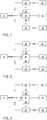
- Fig. 1 the flow of power is represented by arrow symbols.
- the number of arrows exemplarily represents the performance for the respective path in the transmission structure.
- the performance paths are shown by solid lines, on which the arrows for the performance are drawn. Where the performance paths intersect represent intersection points. These can be implemented constructively by a spur gear toothing or other common constructions.
- the power paths connect the drive 14 to summing gears 20, 30 and a motor generator 44, which converts electrical power into mechanical power during engine operation or vice versa.
- the gear structure has two summing gears 20 and 30.
- Summing gears can be designed, for example, as a planetary gear. Each interface of the planetary gear is connected to a branch of the power path.
- This in Figure 1 Upper summing gear 20 is connected to the drive 14 via a power path and at the same time to the further summing gear 30.
- the second power path connects the summing gear 20 to a motor generator 46.
- the third power path connects the summing gear 20 to an output 22 which is in this Example can be the output for driving a PTO.
- the second summing gear 30 is connected to the drive 14 with one power path, to a motor generator 48 with a second power path and to an output of the gear structure, which can be a travel drive 32, with a third power path.
- Power electronics 40 are also provided, which are connected to motor generators 44, 46, 48 is connected and can transfer and control electrical power between them.
- the power electronics 40 is also electrically connected to a further output 42 of the transmission structure, so that electrical power can be output at this output.
- FIG. 1 A mechanical input power on the power path is represented by 4 arrows, which is made available by the drive 14.
- the input power is divided into a power path to the summing gear 20 and a power path to the summing gear 30.
- part of the summing gear 20 represented by an arrow symbol, is branched off from the input power and in the motor generator 46 converted into electrical power. This is passed on to the motor generator 48 by the power electronics, where it is again converted into mechanical power and fed into the summing gear 30.
- the additional power is added to the mechanical power generated by the drive 14 in the summing gear 30 and output to the output 32, the travel drive.
- the output quantity is symbolically represented by three arrow symbols.
- the transmission structure can be used to cover short-term requirements of the drive system, so that there is no shortage of driving performance.
- Fig. 2 shows the gear structure with another concept of power supply.
- the input power from the drive 14 is divided so that a portion, shown by an arrow symbol, is passed to the summing gear 20 and three portions to the summing gear 30.
- the summation gear 30 is controlled in such a way that a portion of the power in the motor generator 48 is converted into electrical power and is fed to the motor generator 46.
- the remaining two parts are made available by the summing gear to the output 32 for the travel drive.
- the motor generator 46 converts the electrical power back into mechanical power, which is then added to the one power component in the summing gear 20.
- the resulting two power components are fed to the output 22 for the PTO drive. This shows how two outputs can be supplied with power by means of the gear structure, with a brief redirection of the power being made possible.
- Fig. 3 The symbolic four power components coming from the drive 14 are divided in such a way that three components are passed to the summing gear 30 and one power component to the motor generator 44. This converts the mechanical power accordingly in electrical power. Controlled by the power electronics 40, the proportion of the power is led to the motor generator 46. In addition, a portion of the mechanical power in the summing gear 30 is branched off and passed to the motor generator 48. There, this is also converted into electrical power, which is passed together with the power portion from the motor generator 44 together to the motor generator 46 and after the conversion into mechanical power via the summing gear 20 to a portion of the output 22 for supply the PTO and is returned to the summing gear 30 in a proportion. The power that is not required for driving the PTO shaft can be redirected, so that further components can be supplied by the transmission structure.
- Fig. 4 shows how, for example, all outputs 22, 32, 42 can be supplied with power at the same time.
- the power is first divided in such a way that one portion is fed into the motor generator 44 and two portions each to the summing gears 20, 30. Through the summing gear, a portion is guided to the assigned motor generators 46, 48 and converted into electrical power.
- the power electronics control the summation of the power components and feeds them to the output 42 for external electrical power supply.
- Fig. 5 shows in a further example that the gear structure makes it possible to route the power from one summing gear to the other summing gear via the power electronics in order to cover a power request at one of the outputs.
- a portion of the mechanical power in the summing gear 20 is branched off and guided through the power electronics.
- the power portion in the summing gear 30 is added to the remaining portion of the mechanical power and passed to the output 32 for the travel drive.
- there can be a difference between the regulation 4 and 5 be switched so that an immediate reaction to the applied loads is made possible.
- the latter In a mode of the transmission structure in which power is delivered to the transmission structure from the outputs, the latter can be directed to the motor generators and recuperated through the summation transmission.
- the electrical power can be stored for later use by means of an energy store.
- a so-called boost function can also be achieved at the outputs which provides a short-term power boost to cover a peak load.
- the proposed gear structure allows the number of mechanical components to be reduced compared to a conventional gear structure, since the full transmission of the mechanical power does not have to be achieved for each output. At the same time, the components can also be designed with a smaller size, so that the mass can be reduced.
Landscapes
- Engineering & Computer Science (AREA)
- General Engineering & Computer Science (AREA)
- Mechanical Engineering (AREA)
- Chemical & Material Sciences (AREA)
- Combustion & Propulsion (AREA)
- Transportation (AREA)
- Motor Power Transmission Devices (AREA)
- Control Of Fluid Gearings (AREA)
- Electric Propulsion And Braking For Vehicles (AREA)
Applications Claiming Priority (1)
| Application Number | Priority Date | Filing Date | Title |
|---|---|---|---|
| DE102018215684.0A DE102018215684A1 (de) | 2018-09-14 | 2018-09-14 | Leistungsverzweigte Getriebestruktur |
Publications (1)
| Publication Number | Publication Date |
|---|---|
| EP3626501A1 true EP3626501A1 (fr) | 2020-03-25 |
Family
ID=67999552
Family Applications (1)
| Application Number | Title | Priority Date | Filing Date |
|---|---|---|---|
| EP19196874.2A Withdrawn EP3626501A1 (fr) | 2018-09-14 | 2019-09-12 | Structure de transmission à dérivation de puissance |
Country Status (3)
| Country | Link |
|---|---|
| US (2) | US11365792B2 (fr) |
| EP (1) | EP3626501A1 (fr) |
| DE (1) | DE102018215684A1 (fr) |
Families Citing this family (1)
| Publication number | Priority date | Publication date | Assignee | Title |
|---|---|---|---|---|
| DE102018215684A1 (de) | 2018-09-14 | 2020-03-19 | Deere & Company | Leistungsverzweigte Getriebestruktur |
Citations (7)
| Publication number | Priority date | Publication date | Assignee | Title |
|---|---|---|---|---|
| DE69702806T2 (de) * | 1996-04-29 | 2000-12-07 | Gen Motors Corp | Hybridantrieb mit Zusatzantrieben |
| DE19749074C2 (de) | 1997-11-06 | 2002-08-29 | Roland Schmetz | Landwirtschaftliches Nutzfahrzeug mit mechanisch-elektrisch leistungsverzweigtem Getriebe |
| US20110178660A1 (en) * | 2004-03-15 | 2011-07-21 | Nicolai Tarasinski | Drive system for a vehicle |
| DE102012204477A1 (de) | 2012-03-21 | 2013-09-26 | Zf Friedrichshafen Ag | Getriebevorrichtung mit wenigstens einem elektrischen Variator zum stufenlosen Variieren einer Übersetzung und mit Leistungsverzweigung |
| DE202014000679U1 (de) * | 2014-01-25 | 2014-02-14 | Ursula Kalinowski-Krumm | Einwelliger Antriebsstrang mit Hybridantrieb für eine Arbeitsmaschine ohne Zwischengetriebe und mit weiteren Leistungs-Nebenverbrauchern |
| DE102016206205A1 (de) * | 2016-04-13 | 2017-10-19 | Zf Friedrichshafen Ag | Leistungsverzweigter Antriebsstrang für eine Arbeitsmaschine |
| DE102016221343A1 (de) * | 2016-10-28 | 2018-05-03 | Zf Friedrichshafen Ag | Leistungsverzweigter Antriebsstrang für eine Arbeitsmaschine |
Family Cites Families (8)
| Publication number | Priority date | Publication date | Assignee | Title |
|---|---|---|---|---|
| DE102005044179A1 (de) * | 2005-09-15 | 2007-05-10 | Deere & Company, Moline | Antriebssystem für ein landwirtschaftliches oder industrielles Nutzfahrzeug |
| US20130068068A1 (en) * | 2011-09-19 | 2013-03-21 | Holger Witt | Modulated shifting transmission with parallel power paths. |
| DE102014221916A1 (de) * | 2013-11-19 | 2015-05-21 | Schaeffler Technologies Gmbh & Co. Kg | Getriebe |
| DE102014221914A1 (de) * | 2013-11-19 | 2015-05-21 | Schaeffler Technologies Gmbh & Co. Kg | Antriebsstrang für Fahrzeuge |
| DE102013224383A1 (de) * | 2013-11-28 | 2015-05-28 | Zf Friedrichshafen Ag | Leistungsverzweigter Achsantrieb für Arbeitsmaschinen |
| DE102015208160B4 (de) * | 2014-09-25 | 2025-07-03 | Deere & Company | Getriebesteuerverfahren |
| DE102016206204B4 (de) * | 2016-04-13 | 2025-03-13 | Zf Friedrichshafen Ag | Leistungsverzweigter Antriebsstrang für eine Arbeitsmaschine |
| DE102018215684A1 (de) | 2018-09-14 | 2020-03-19 | Deere & Company | Leistungsverzweigte Getriebestruktur |
-
2018
- 2018-09-14 DE DE102018215684.0A patent/DE102018215684A1/de active Pending
-
2019
- 2019-09-09 US US16/565,108 patent/US11365792B2/en active Active
- 2019-09-12 EP EP19196874.2A patent/EP3626501A1/fr not_active Withdrawn
-
2022
- 2022-04-21 US US17/726,245 patent/US12181030B2/en active Active
Patent Citations (7)
| Publication number | Priority date | Publication date | Assignee | Title |
|---|---|---|---|---|
| DE69702806T2 (de) * | 1996-04-29 | 2000-12-07 | Gen Motors Corp | Hybridantrieb mit Zusatzantrieben |
| DE19749074C2 (de) | 1997-11-06 | 2002-08-29 | Roland Schmetz | Landwirtschaftliches Nutzfahrzeug mit mechanisch-elektrisch leistungsverzweigtem Getriebe |
| US20110178660A1 (en) * | 2004-03-15 | 2011-07-21 | Nicolai Tarasinski | Drive system for a vehicle |
| DE102012204477A1 (de) | 2012-03-21 | 2013-09-26 | Zf Friedrichshafen Ag | Getriebevorrichtung mit wenigstens einem elektrischen Variator zum stufenlosen Variieren einer Übersetzung und mit Leistungsverzweigung |
| DE202014000679U1 (de) * | 2014-01-25 | 2014-02-14 | Ursula Kalinowski-Krumm | Einwelliger Antriebsstrang mit Hybridantrieb für eine Arbeitsmaschine ohne Zwischengetriebe und mit weiteren Leistungs-Nebenverbrauchern |
| DE102016206205A1 (de) * | 2016-04-13 | 2017-10-19 | Zf Friedrichshafen Ag | Leistungsverzweigter Antriebsstrang für eine Arbeitsmaschine |
| DE102016221343A1 (de) * | 2016-10-28 | 2018-05-03 | Zf Friedrichshafen Ag | Leistungsverzweigter Antriebsstrang für eine Arbeitsmaschine |
Also Published As
| Publication number | Publication date |
|---|---|
| US11365792B2 (en) | 2022-06-21 |
| US20200088279A1 (en) | 2020-03-19 |
| DE102018215684A1 (de) | 2020-03-19 |
| US20220243794A1 (en) | 2022-08-04 |
| US12181030B2 (en) | 2024-12-31 |
Similar Documents
| Publication | Publication Date | Title |
|---|---|---|
| EP3006245B1 (fr) | Procede de commande de transmission | |
| DE102007021591B4 (de) | Getriebe mit einem Modus und Verbundleistungsverzweigung und doppelten mechanischen Wegen und festem Reduktionsverhältnis | |
| EP2764280B1 (fr) | Transmission à dérivation de puissance | |
| DE102006060063A1 (de) | Elektrisch verstellbares Getriebe mit einem Bereich und einer Sperrkupplung und Verfahren zum Betieb | |
| WO2009021913A2 (fr) | Procédé pour déplacer le point de charge en fonctionnement hybride pour un véhicule à fonctionnement hybride en parallèle | |
| DE102012204477B4 (de) | Getriebevorrichtung mit wenigstens einem elektrischen Variator zum stufenlosen Variieren einer Übersetzung und mit Leistungsverzweigung | |
| DE102012216781A1 (de) | Antriebstrang für Fahrzeuge | |
| DE19955312B4 (de) | Antriebssystem für Flurförderzeuge | |
| DE102018209940A1 (de) | Stufenloses Multimode-Getriebe für nahtloses Schalten | |
| EP3354504B1 (fr) | Système d'entrainement du groupe motopropulseur | |
| DE102022210867A1 (de) | Elektronisch verstellbares doppelpfad-lastschaltgetriebe für arbeitsfahrzeuge | |
| DE102019214355A1 (de) | Antriebssystem eines land- oder bauwirtschaftlich nutzbaren Fahrzeugs und Verfahren zu dessen Betrieb gemeinsam mit einem zumindest einen elektrischen Verbraucher aufweisenden Anbaugerät | |
| DE19955313A1 (de) | Antriebssystem für Flurförderzeuge | |
| DE102016206205B4 (de) | Leistungsverzweigter Antriebsstrang für eine Arbeitsmaschine | |
| DE102023102285A1 (de) | Planetensystem mit mehreren Leistungsquellen für eine Maschine | |
| EP3626501A1 (fr) | Structure de transmission à dérivation de puissance | |
| DE102019200966B4 (de) | Leistungsverzweigtes Kraftfahrzeuggetriebe | |
| DE10350308B4 (de) | Verfahren zur Motordrehzahl- und Übersetzungswahl bei einem stufenlosen hydrostatischen Leistungsverzweigungsgetriebe | |
| DE102006036443A1 (de) | Vorrichtung zum Steuern eines Hybridantriebs | |
| DE102016218159A1 (de) | Antriebsanordnung mit einer leistungsverzweigten Getriebevorrichtung | |
| DE102016206204B4 (de) | Leistungsverzweigter Antriebsstrang für eine Arbeitsmaschine | |
| DE10129488A1 (de) | Antriebssystem für einen Generator, insbesondere Generatorantrieb | |
| DE112020000253T5 (de) | Stufenloses multimode-getriebe mit sowohl einer drehzahlkopplung als auch einer drehmomentkopplung | |
| DE102021001651A1 (de) | Elektrifiziertes Radien-Überlagerungslenkgetriebe | |
| EP3239559B1 (fr) | Entraînement pour une machine de travail automobile et unité d'entraînement |
Legal Events
| Date | Code | Title | Description |
|---|---|---|---|
| PUAI | Public reference made under article 153(3) epc to a published international application that has entered the european phase |
Free format text: ORIGINAL CODE: 0009012 |
|
| STAA | Information on the status of an ep patent application or granted ep patent |
Free format text: STATUS: THE APPLICATION HAS BEEN PUBLISHED |
|
| AK | Designated contracting states |
Kind code of ref document: A1 Designated state(s): AL AT BE BG CH CY CZ DE DK EE ES FI FR GB GR HR HU IE IS IT LI LT LU LV MC MK MT NL NO PL PT RO RS SE SI SK SM TR |
|
| AX | Request for extension of the european patent |
Extension state: BA ME |
|
| STAA | Information on the status of an ep patent application or granted ep patent |
Free format text: STATUS: REQUEST FOR EXAMINATION WAS MADE |
|
| 17P | Request for examination filed |
Effective date: 20200925 |
|
| RBV | Designated contracting states (corrected) |
Designated state(s): AL AT BE BG CH CY CZ DE DK EE ES FI FR GB GR HR HU IE IS IT LI LT LU LV MC MK MT NL NO PL PT RO RS SE SI SK SM TR |
|
| STAA | Information on the status of an ep patent application or granted ep patent |
Free format text: STATUS: EXAMINATION IS IN PROGRESS |
|
| 17Q | First examination report despatched |
Effective date: 20210628 |
|
| STAA | Information on the status of an ep patent application or granted ep patent |
Free format text: STATUS: THE APPLICATION IS DEEMED TO BE WITHDRAWN |
|
| 18D | Application deemed to be withdrawn |
Effective date: 20211109 |