EP3626527B1 - Assistance à l'extension pour appuie-tête - Google Patents
Assistance à l'extension pour appuie-tête Download PDFInfo
- Publication number
- EP3626527B1 EP3626527B1 EP19194112.9A EP19194112A EP3626527B1 EP 3626527 B1 EP3626527 B1 EP 3626527B1 EP 19194112 A EP19194112 A EP 19194112A EP 3626527 B1 EP3626527 B1 EP 3626527B1
- Authority
- EP
- European Patent Office
- Prior art keywords
- extension
- assembly
- headrest
- assist
- backrest
- Prior art date
- Legal status (The legal status is an assumption and is not a legal conclusion. Google has not performed a legal analysis and makes no representation as to the accuracy of the status listed.)
- Active
Links
Images




Classifications
-
- B—PERFORMING OPERATIONS; TRANSPORTING
- B60—VEHICLES IN GENERAL
- B60N—SEATS SPECIALLY ADAPTED FOR VEHICLES; VEHICLE PASSENGER ACCOMMODATION NOT OTHERWISE PROVIDED FOR
- B60N2/00—Seats specially adapted for vehicles; Arrangement or mounting of seats in vehicles
- B60N2/80—Head-rests
- B60N2/806—Head-rests movable or adjustable
- B60N2/809—Head-rests movable or adjustable vertically slidable
- B60N2/829—Head-rests movable or adjustable vertically slidable characterised by their adjusting mechanisms, e.g. electric motors
-
- B—PERFORMING OPERATIONS; TRANSPORTING
- B60—VEHICLES IN GENERAL
- B60N—SEATS SPECIALLY ADAPTED FOR VEHICLES; VEHICLE PASSENGER ACCOMMODATION NOT OTHERWISE PROVIDED FOR
- B60N2/00—Seats specially adapted for vehicles; Arrangement or mounting of seats in vehicles
- B60N2/80—Head-rests
- B60N2/806—Head-rests movable or adjustable
- B60N2/809—Head-rests movable or adjustable vertically slidable
-
- B—PERFORMING OPERATIONS; TRANSPORTING
- B60—VEHICLES IN GENERAL
- B60N—SEATS SPECIALLY ADAPTED FOR VEHICLES; VEHICLE PASSENGER ACCOMMODATION NOT OTHERWISE PROVIDED FOR
- B60N2/00—Seats specially adapted for vehicles; Arrangement or mounting of seats in vehicles
- B60N2/80—Head-rests
- B60N2/897—Head-rests with sleeves located in the back-rest for guiding the rods of the head-rest
-
- B—PERFORMING OPERATIONS; TRANSPORTING
- B64—AIRCRAFT; AVIATION; COSMONAUTICS
- B64D—EQUIPMENT FOR FITTING IN OR TO AIRCRAFT; FLIGHT SUITS; PARACHUTES; ARRANGEMENT OR MOUNTING OF POWER PLANTS OR PROPULSION TRANSMISSIONS IN AIRCRAFT
- B64D11/00—Passenger or crew accommodation; Flight-deck installations not otherwise provided for
- B64D11/06—Arrangements of seats, or adaptations or details specially adapted for aircraft seats
- B64D11/0639—Arrangements of seats, or adaptations or details specially adapted for aircraft seats with features for adjustment or converting of seats
- B64D11/0642—Adjustable headrests
Definitions
- the instant invention relates to extension assists for headrests, for example of aircraft seats.
- headrest extension assemblies may be advantageous.
- the added support of headrest extension assemblies becomes increasingly important in emergency situations, such as crashes, where supporting the head and neck of vehicle occupants is of utmost importance.
- seat backrests become shorter, headrest extension assemblies become larger and heavier.
- Increasingly heavy headrest extension assemblies may be difficult for vehicle occupants to move and adjust, particularly from a seated position. Consequently, there is a need in the art for headrest and/or backrest assemblies that cure one or more shortfalls identified above.
- German utility model DE 20 2013 009391 U1 discloses a seat device with backrest and headrest in motor vehicles, airplanes and ships. Between the backrest covering at the front and the backrest covering at the rear in the backrest interior there is a mechanical device in this a guide carriage. The headrest can be pushed into the backrest interior and is locked in the pushed-in headrest position of the headrest by the guide carriage lock. By a switching unit in the seat part, the headrest, which is located between the front backrest covering and the rear backrest covering in the backrest interior, is switched back on when the seat part is relieved transported from the backrest interior by means of a mechanical device in the headrest position.
- the present invention provides a solution for this need and provides an extension assist system.
- the system includes an extension assembly and an extension assist assembly.
- the extension assembly is configured to translate along a movement axis between at least a retracted position and an extended position.
- the extension assist assembly includes an extension panel and one or more extension members movably connected to a body assembly, and is configured to exert an extension force parallel to the movement axis, wherein the extension force is less than an extension resistance force acting parallel to the movement axis in a direction opposite the extension force.
- the "extension resistance force” is the resistance force that has to be overcome.
- an extension resistance force acting is to interpreted broadly and includes a continuously acting resistance force as well as a resisting force that is present (only) as a counter force when an extension force is applied, and combinations thereof.
- the extension force of the extension assist assembly is applied continuously.
- the extension resistance force can be a result of the extension force applied by the extension assist assembly and any other forces applied (simultaneously).
- a skilled person will know how to measure one of the forces and how to adjust the other of the forces, to meet the requirement according to the invention.
- the system includes a headrest extension assembly.
- the headrest extension assembly includes a headrest and one or more extension members movably coupled to a backrest assembly of a seat, and is configured to translate along a movement axis between at least a retracted position and an extended position.
- the system also includes an extension assist assembly configured to exert an extension force parallel to the movement axis, wherein the extension force is less than an extension resistance force acting parallel to the movement axis in a direction opposite the extension force. This can be achieved in many ways and the required extension resistance force may differ for different kinds of seats.
- This "configured to exert” may be interpreted as “comprises a device (such as a gas spring) that exerts”.
- the instant invention relates to a seat, for example a vehicle seat such as an aircraft seat comprising a backrest and a headrest and an extension assist system according to the first aspect of the instant invention.
- a letter following a reference numeral is intended to reference an embodiment of the feature or element that may be similar, but not necessarily identical, to a previously described element or feature bearing the same reference numeral (e.g., 1, 1A, 1B).
- reference numeral e.g. 1, 1A, 1B
- Such shorthand notations are used for purposes of convenience only, and should not be construed to limit the invention in any way unless expressly stated to the contrary.
- any reference to "one embodiment,” or “some embodiments” means that a particular element, feature, structure, or characteristic described in connection with the embodiment is included in at least one embodiment of the present invention.
- the appearances of the phrase “in some embodiments” in various places in the specification are not necessarily all referring to the same embodiment, and embodiments of the present invention one or more of the features expressly described or inherently present herein, or any combination of sub-combination of two or more such features, along with any other features which may not necessarily be expressly described or inherently present in the instant disclosure.
- embodiments of the present invention are directed to an extension assist system for headrests and/or backrests. Additional embodiments of the present invention are directed to the use of an extension assist assembly to counter-balance the weight of a headrest extension assembly, thereby allowing for easier movement of the headrest extension assembly. Additional embodiments of the present invention are directed to the use of an extension assist assembly configured to dampen the motion of a headrest extension assembly relative to a backrest assembly. In addition to facilitating smooth, luxurious extension and retraction of the headrest extension assembly, the assisted motion of the headrest extension assembly may provide added support and comfort for seat occupants.
- headrest extension assemblies may be required in some aircraft and other vehicles with shorter seat backrests in order to support the head, neck, and back of vehicle occupants.
- headrest extension assemblies may be required in some aircraft and other vehicles with shorter seat backrests in order to support the head, neck, and back of vehicle occupants.
- headrest extension assemblies may become larger, they often become heavier and increasingly difficult for vehicle occupants to move and adjust, particularly from a seated position.
- the force required to adjust heavy headrest extension assemblies may be awkward, difficult, or even impossible to achieve from a seated position.
- embodiments of the present invention may facilitate the movement of headrest and/or backrest extension assemblies for easier, smoother adjustment.
- FIGS. 1A-5 systems and apparatuses for headrest extension assistance are shown and described, in accordance with one or more embodiments of the present invention.
- the present invention may be incorporated in the seats of an aircraft in order to facilitate the movement of the headrests on the seats of the aircraft.
- aircraft passengers may be able to quickly and easily adjust the headrests of their seats from both a standing and seated position.
- the present invention may be configured to operate in any type of seat and/or vehicle known in the art.
- the embodiments of the present invention may be incorporated into the seats of any air, land, or water-based personal equipment or vehicle; any air, land, or water-based commercial equipment or vehicle; any air, land, or water-based military equipment or vehicle known in the art.
- embodiments of the present invention may be incorporated into the seat of an automobile.
- embodiments may be described throughout the present disclosure in an aircraft environment. However, these references are not to be regarded as limiting. Thus, references to "aircraft,” “airplanes,” “avionics,” and like terms should not be interpreted as a limitation on the present invention, unless noted otherwise herein.
- FIG. 1A illustrates a rear view of an extension assist system 100 in a retracted position, in accordance with one or more embodiments of the present invention.
- extension assist system 100 (“system 100") may include a headrest extension assembly 102 as example of an extension assembly, a backrest assembly 104 as an example of a body assembly, and an extension assist assembly 106.
- the seat of an aircraft may include, among other elements, headrest extension assembly 102 and backrest assembly 104.
- the headrest extension assembly 102 includes a headrest 108 and one or more extension members 112.
- the backrest assembly 104 may include a backrest frame 114 and one or more ports 116.
- Headrest extension assembly 102 is configured to be movably coupled to the backrest assembly 104.
- the one or more extension members 112 of the headrest extension assembly 102 may be configured to slidingly couple with the backrest assembly 104 via the one or more ports 116.
- the one or more extension members 112 may slide "up" and “down” as depicted in FIG. 1A , within the one or more ports 116 of the backrest assembly 104.
- the one or more ports 116 may include any ports or components known in the art including, but not limited to, one or more gaskets, one or more sleeves, and the like.
- the headrest extension assembly 102 is movably coupled to backrest assembly 104 such that headrest extension assembly 102 is configured to translate along a movement axis 118.
- the headrest extension assembly 102 may be configured to translate along the movement axis 118 to any number of positions including, but not limited to, a retracted position (as shown in FIG. 1A ), an intermediate position, and an extended position (as shown in FIG. 1B , described in greater detail herein).
- the headrest extension assembly 102 may be translated along movement axis 118 in an infinite number of positions.
- system 100 may provide for greater flexibility in adjusting the position of the headrest extension assembly 102.
- headrest extension assembly 102 is depicted as being movably couplable to the backrest assembly 104 via one or more ports, this is provided as an example for illustrative purposes.
- the headrest extension assembly 102 may be movably couplable to the backrest assembly 104 in any manner known in the art including, but not limited to, one or more ports, one or more tracks, and the like.
- the one or more extension members 112 are coupled to an extension assist apparatus 106 as an example of an extension assist assembly.
- the extension assist apparatus 106 may include any extension apparatus known in the art which may be configured to assert an extension force (or a component of an extension force) "upward" parallel to the movement axis 118.
- the extension assist apparatus 106 may include a gas spring, a gas strut, or a mechanical strut.
- the extension assist assembly 106 includes a damper configured to control the speed at which the headrest extension assembly 102 translates along the movement axis 118.
- the one or more extension members 112 may be coupled to the extension assist assembly 106 with one or more fasteners 122.
- the extension assist apparatus 106 may be coupled to the backrest assembly 104 at an attachment point 126 via one or more fasteners 124.
- the one or more fasteners 122, 124 may include any fastening means known in the art configured to couple the extension assist assembly 106 to the one or more extension members 112 and the backrest assembly 104.
- the one or more fasteners 122, 124 may include, but are not limited to, one or more screws, one or more nuts/bolts, one or more pins (e.g., hitch and pin, cotter pin, split pin, locking pin), one or more clamps, one or more adhesives, and one or more snaps.
- the extension assist assembly 106 is coupled to a mounting bracket 128 affixed to the backrest assembly 104.
- FIG. 1A depicts the extension assist assembly 106 as attaching to an attachment point 126 located on the backrest assembly 104, this is not to be regarded as a limitation of the present invention.
- the extension assist assembly 106 may be coupled to an attachment point 126 which is stationary with respect to the headrest extension assembly 102.
- the extension assist assembly 106 may be coupled to an attachment point 126 which is located on the floor upon which the seat and backrest assembly 104 is situated.
- the extension assist assembly 106 may be coupled to an attachment point 126 which is located on a mounting bracket 128 which extends from the floor.
- the extension assist assembly 106 may be coupled to any fixed point relative to the headrest extension assembly 102.
- FIG. 1A illustrates the extension assist assembly 106 coupled directly to the one or more extension members 112 via one or more fasteners 122, this is not to be regarded as a limitation of the present invention, unless noted otherwise herein.
- the extension assist assembly 106 may be coupled indirectly to the one or more extension members 112.
- the extension assist assembly 106 may be coupled to a linking member which links the one or more extension members 112 together.
- the extension assist assembly 106 is configured to exert an extension force (or a component of an extension force) upon the headrest extension assembly 102 which is parallel with the movement axis 118.
- the extension force exerted by the extension assist assembly 106 may offset, or partially offset, an extension resistance force which acts parallel to the movement axis 118 in the opposite direction as the extension force.
- gravity may act as an extension resistance force, pulling the headrest down parallel (or substantially parallel) to the movement axis 118.
- the extension assist apparatus 106 may exert an extension force upward parallel (or substantially parallel) to the movement axis 118 such that it offsets, or partially offsets, the force of gravity acting upon the mass of the headrest extension assembly 102.
- the extension resistance force may allow a passenger of an aircraft to extend the headrest extension assembly 102 with less force, thereby providing a smoother, more luxurious flying experience.
- the extension force exerted by the extension assist assembly 106 may be based on a number of factors including, but not limited to, the force desired to extend the headrest extension assembly 102, and the magnitude of the extension resistance force, which may be affected by the mass of the headrest extension assembly 102, forces of friction, and the like. Accordingly, system 100 and extension assist assembly 106 may be tailored on a bespoke basis dependent on any number of factors including, but not limited to, the type of aircraft, particular passengers, desired flying experience, need for adjustability, frequency of adjustments, and the like.
- the extension assist assembly 106 may be tailored such that the extension force is between 0.9 and 2.3 kg (two and five pounds) less than the extension resistance force, such that only two to five pounds of force is required to extend the headrest extension assembly 102 from a retracted position to an intermediate or extended position.
- the extension assist assembly 106 may include a gas spring.
- the extension assist assembly 106 gas spring
- FIGS. 1A and 1B illustrate an extension assist assembly 106 which may be loaded in compression.
- FIG. 1B illustrates a rear view of an extension assist system 100 in an extended position, in accordance with one or more embodiments of the present invention.
- FIG. 1A illustrates system 100 in a retracted position (e.g., stowed position)
- FIG. 1B illustrates system 100 in an extended position.
- FIGS. 1A and 1B illustrate an extension assist assembly 106 which is loaded in compression.
- a first end of the extension assist assembly 106 coupled to an extension member 112.
- a second end of the extension assist assembly 106 may be coupled to the backrest assembly 104 at an attachment point 126 located on the backrest assembly 104 substantially opposite the headrest extension assembly 104.
- the headrest extension assembly 102 when the extension assist assembly 106 is in a contracted/retracted state, the headrest extension assembly 102 is also in a retracted position (e.g., stowed position), as shown in FIG. 1A .
- FIG. 1B when the extension assist apparatus 106 is in an extended state, the headrest extension assembly 102 is also in an extended state.
- the extension assist assembly 106 loaded in compression, resists compression such that it exerts an extension force along the movement axis 118.
- system 100 may be used in environments other than the headrest of a seat.
- system 100 may be used to facilitate the movement of any extendable component, such as, but not limited to, a seat pan, a leg rest, a foot rest, or extensions of the same.
- system 100 may be incorporated in a foot rest configuration.
- system 100 includes an "extension assembly 102" (instead of headrest extension assembly 102) and a "body assembly 104" (instead of backrest assembly 104).
- the extension assembly 102 includes an "extension panel 108" and one or more extension members 112. Therefore, although embodiments of the present invention are shown and described in the environment of an extendable headrest, it is contemplated that the present invention may be used in other environments.
- FIG. 2A illustrates a perspective view of an extension assist system 100 in a retracted (stowed) position, in accordance with one or more embodiments of the present invention.
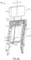
- FIG. 2B illustrates a perspective view of an extension assist system 100 in an extended position, in accordance with one or more embodiments of the present invention.
- system 100 may include a headrest extension assembly 102, a backrest assembly 104, and an extension assist assembly 106.
- headrest extension assembly 102 is coupled to the backrest assembly 104 such that the headrest extension assembly 102 translates along the movement axis 118.
- extension assist assembly 106 may be aligned along movement axis 118 such that the extension force exerted by the extension assist assembly 106 is parallel to the movement axis 118.
- the extension assist assembly 106 may not be aligned along the movement axis 118.
- the extension assist assembly 106 may be positioned along an extension axis 132 which is different from the movement axis 118. In this regard, only a component of the extension force exerted by the extension assist assembly 106 may be parallel to the movement axis 118.
- the relative angles between the extension axis 132 and the movement axis 118 may change as the headrest extension assembly 102 moves from a retracted position to an extended position, and vis versa.
- the relative angles between the extension axis 132 and the movement axis 118 may vary when the headrest extension assembly 102 is in an extended or retracted position.
- the one or more fasteners 122, 124 may be configured to couple the extension assist assembly 106 to the extension member 112 and the backrest assembly 104 at a number of different angles.
- the one or more fasteners 122, 124 may include a hitch and pin which may be configured to allow the extension assist assembly 106 to rotate relative to the extension member 112 as the headrest extension assembly 102 is translated along the movement axis 118.
- FIG. 3A illustrates a rear view of an extension assist system 100 in a retracted position, in accordance with one or more embodiments of the present invention.
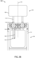
- FIG. 3B illustrates a rear view of an extension assist system 100 in an extended position, in accordance with one or more embodiments of the present invention.
- system 100 may include a headrest extension assembly 102, a backrest assembly 104, and an extension assist assembly 106.
- a first end of the extension assist assembly 106 may be coupled to an extension member 112 via one or more fasteners 122.
- a second end of the extension assist assembly 106 may be coupled to the backrest assembly 104 at an attachment point 134.
- the extension assist assembly 106 may be coupled to the backrest assembly 104 at multiple points.
- the extension assist assembly 106 is coupled to the backrest assembly 104 at attachment point 126 which is located on the backrest assembly 104 at a point which is substantially opposite the headrest extension assembly 102 and/or one or more ports 116.
- the extension assist assembly 106 is coupled to the backrest assembly 104 at attachment point 134 which is located on the backrest assembly 104 at a point which is proximate to the headrest extension assembly 102 and/or one or more ports 106.
- the extension assist assembly 106 may include a gas spring.
- the extension assist assembly 106 gas spring
- FIGS. 3A and 3B illustrate an extension assist assembly 106 which may be loaded in extension.
- FIGS. 3A and 3B illustrate an extension assist assembly 106 which is loaded in extension.
- a first end of the extension assist assembly 108 is coupled to an extension member 112.
- a second end of the extension assist assembly 106 is coupled to the backrest assembly 104 at attachment point 134 which is located on the backrest assembly 104 at a point which is proximate to the headrest extension assembly 102 and/or one or more ports 106.
- the headrest extension assembly 102 is in a retracted position (e.g., stowed position), as shown in FIG. 3A .
- a retracted position e.g., stowed position
- the extension assist assembly 106 when the extension assist apparatus 106 is in a retracted state, the headrest extension assembly 102 is in an extended state. Accordingly, the extension assist assembly 106, loaded in extension, resists extension such that it exerts an extension force along the movement axis 118.
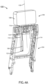
- FIG. 4A illustrates a perspective view of an extension assist system 100 in a retracted (stowed) position, in accordance with one or more embodiments of the present invention.
- FIG. 4B illustrates a perspective view of an extension assist system 100 in an extended position, in accordance with one or more embodiments of the present invention.
- extension assist assembly 106 may be coupled to the backrest assembly 104 at attachment point 134.
- this is not to be regarded as a limitation on the scope of the present invention.
- extension assist assembly 106 may be coupled to the backrest assembly 104 at attachment point 134 located proximate to the one or more ports 106 such that the extension axis 132 and movement axis 118 are not parallel to one another.
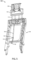
- FIG. 5 illustrates a perspective view of an extension assist system 100 including a backrest extension assembly 142 and an extending headrest assembly 138, in accordance with one or more embodiments of the present invention.
- System 100 may include, but is not limited to, a backrest assembly 104, and an extension assist assembly 106, one or more extension members 112, a backrest extension assembly 142, an extending headrest assembly 138, and a means for extending the extending headrest assembly 138.
- System 100 as illustrated in FIG. 5 , is described in more detail in United States Patent Application No. [Attorney Docket No. MI218-08] entitled "MULTI-STAGE SEATBACK EXTENSION SYSTEM" filed September 12, 2018.
- any two components herein combined to achieve a particular functionality can be seen as “associated with” each other such that the desired functionality is achieved, irrespective of architectures or intermedial components.
- any two components so associated can also be viewed as being “connected,” or “coupled,” to each other to achieve the desired functionality, and any two components capable of being so associated can also be viewed as being “couplable,” to each other to achieve the desired functionality.
- Specific examples of couplable include but are not limited to physically mateable and/or physically interacting components.
Landscapes
- Engineering & Computer Science (AREA)
- Aviation & Aerospace Engineering (AREA)
- Transportation (AREA)
- Mechanical Engineering (AREA)
- Seats For Vehicles (AREA)
Claims (10)
- Système d'aide à l'extension (100), comprenant :un ensemble d'extension (102) comprenant un panneau d'extension (108) et un ou plusieurs éléments d'extension (112) configurés pour être reliés de manière mobile à un ensemble corps (104)l'ensemble d'extension étant configuré pour se déplacer en translation le long d'un axe de mouvement (118) entre au moins une position rétractée et une position déployée ; etun ensemble d'aide à l'extension (106) doté d'une première extrémité et d'une seconde extrémité, la première extrémité étant couplée à l'élément ou aux plusieurs éléments d'extension (112) et la seconde extrémité étant couplée à un point fixe par rapport à l'ensemble d'extension (102), l'ensemble d'aide à l'extension (106) étant configuré pour exercer une force d'extension parallèle à l'axe de mouvement (118), caractérisé en ce que la force d'extension est inférieure à une force de résistance à l'extension agissant parallèlement à l'axe de mouvement (118) dans une direction opposée à la force d'extension.
- Système d'aide à l'extension selon la revendication 1, dans lequel l'ensemble d'aide à l'extension (106) comprend un ensemble ressort à gaz.
- Système d'aide à l'extension selon la revendication 1 ou 2, dans lequel l'ensemble d'aide à l'extension est chargé en compression et est configuré pour s'étendre le long d'un axe d'extension pour déplacer en translation l'ensemble d'extension de la position rétractée à la position déployée.
- Système d'aide à l'extension selon la revendication 1 ou 2, dans lequel l'ensemble d'aide à l'extension (106) est chargé en extension et est configuré pour se rétracter le long d'un axe d'extension pour déplacer en translation l'ensemble d'extension (102) de la position rétractée à la position déployée.
- Système d'aide à l'extension selon une ou plusieurs des revendications 1 à 4, dans lequel la force d'extension est inférieure de 0,9 kg à 2,3 kg (deux et cinq livres) à la force de résistance à l'extension.
- Système d'aide à l'extension selon une ou plusieurs des revendications 1 à 5, dans lequel l'ensemble d'aide à l'extension (106) est configuré pour s'étendre le long d'un axe d'extension qui est parallèle à l'axe de mouvement (118).
- Système d'aide à l'extension selon une ou plusieurs des revendications 1 à 5, dans lequel l'ensemble d'aide à l'extension (106) est configuré pour s'étendre le long d'un axe d'extension qui n'est pas parallèle à l'axe de mouvement (118).
- Système d'aide à l'extension selon une ou plusieurs des revendications 1 à 7, dans lequel le panneau d'extension (108) est compris dans un appui-tête (108).
- Système d'aide à l'extension selon une ou plusieurs des revendications 1 à 8, dans lequel les éléments d'extension (112) sont configurés pour être reliés de manière mobile à un ensemble dossier (104).
- Siège comprenant un fond de siège, un ensemble dossier (104) et un appui-tête (108), le siège comprenant en outre un système d'aide à l'extension de l'appui-tête (100) selon une ou plusieurs des revendications 1 à 9 et dans lequel le ou les plusieurs éléments d'extension (112) sont reliés de manière mobile à l'ensemble dossier (104).
Applications Claiming Priority (1)
| Application Number | Priority Date | Filing Date | Title |
|---|---|---|---|
| US16/128,749 US10668844B2 (en) | 2018-09-12 | 2018-09-12 | Extension assist for headrest |
Publications (2)
| Publication Number | Publication Date |
|---|---|
| EP3626527A1 EP3626527A1 (fr) | 2020-03-25 |
| EP3626527B1 true EP3626527B1 (fr) | 2024-06-12 |
Family
ID=67777215
Family Applications (1)
| Application Number | Title | Priority Date | Filing Date |
|---|---|---|---|
| EP19194112.9A Active EP3626527B1 (fr) | 2018-09-12 | 2019-08-28 | Assistance à l'extension pour appuie-tête |
Country Status (3)
| Country | Link |
|---|---|
| US (1) | US10668844B2 (fr) |
| EP (1) | EP3626527B1 (fr) |
| CN (1) | CN110893809B (fr) |
Families Citing this family (5)
| Publication number | Priority date | Publication date | Assignee | Title |
|---|---|---|---|---|
| JP6622109B2 (ja) * | 2016-02-16 | 2019-12-18 | 株式会社タチエス | シート構造 |
| DE102019135393A1 (de) * | 2019-12-20 | 2021-06-24 | Recaro Aircraft Seating Gmbh & Co. Kg | Flugzeugsitzvorrichtung, Flugzeugsitz, Verfahren zur Herstellung der Flugzeugsitzvorrichtung und Baukastensystem |
| US11679883B2 (en) * | 2020-08-17 | 2023-06-20 | Ami Industries, Inc. | Adjustable single axis tensioner for movable aircraft headrests |
| GB2607889B (en) * | 2021-06-11 | 2025-02-26 | Safran Seats Gb Ltd | Aircraft seat with moveable headrest |
| DE102023128971A1 (de) * | 2023-10-20 | 2025-04-24 | Recaro Aircraft Seating Gmbh & Co. Kg | Passagiersitzvorrichtung |
Family Cites Families (12)
| Publication number | Priority date | Publication date | Assignee | Title |
|---|---|---|---|---|
| FR1522431A (fr) * | 1967-03-07 | 1968-04-26 | Dispositif de sécurité et de confort aux dossiers de sièges pour passagers de véhicules à grande vitesse | |
| DE7920475U1 (de) * | 1979-07-18 | 1979-11-08 | P.A. Rentrop, Hubbert & Wagner Fahrzeugaustattungen Gmbh & Co Kg, 3060 Stadthagen | Hoehenverstellbare kopfstuetze eines kraftfahrzeugsitzes |
| DE3621278A1 (de) * | 1986-06-25 | 1988-01-21 | Opel Adam Ag | Umlegbare kopfstuetze fuer einen fahrzeugsitz, insbesondere fuer einen ruecksitz eines personenwagens |
| US5316370A (en) * | 1992-11-16 | 1994-05-31 | Newman Engineering Inc. | Seat assist |
| US5823619A (en) * | 1996-03-04 | 1998-10-20 | Trw Occupant Restraint Systems Gmbh | Vehicle seat |
| ATE421931T1 (de) | 2004-05-14 | 2009-02-15 | Alfmeier Praez Ag | Fahrzeugsitz mit einer kopfstütze |
| DE102005006116A1 (de) * | 2004-11-12 | 2006-05-18 | Schukra Gerätebau AG | Verstellvorrichtung für eine Kopfstütze |
| CN103818284B (zh) * | 2008-01-11 | 2016-03-23 | 提爱思科技股份有限公司 | 头枕支撑构造 |
| FR2937007B1 (fr) | 2008-10-15 | 2010-12-31 | Recaro Aircraft Seating Gmbh Co | Unite de siege passager. |
| DE102011081737A1 (de) * | 2011-08-29 | 2013-02-28 | Lear Corp. | Verstellbare Fahrzeugsitz-Kopfstützenanordnung |
| CN203221904U (zh) * | 2013-03-11 | 2013-10-02 | 麦克英孚(宁波)婴童用品有限公司 | 一种车用儿童安全座椅 |
| DE202013009391U1 (de) | 2013-10-22 | 2014-04-23 | Walter Fritsche | Fahrzeugsitz für Fahrzeuge aller Art mit zwangsgesteuerter ein- u. ausfahrbarer Kopfstütze in die Rückenlehne |
-
2018
- 2018-09-12 US US16/128,749 patent/US10668844B2/en active Active
-
2019
- 2019-08-28 EP EP19194112.9A patent/EP3626527B1/fr active Active
- 2019-09-12 CN CN201910861286.5A patent/CN110893809B/zh active Active
Also Published As
| Publication number | Publication date |
|---|---|
| US20200079261A1 (en) | 2020-03-12 |
| CN110893809B (zh) | 2023-08-22 |
| EP3626527A1 (fr) | 2020-03-25 |
| US10668844B2 (en) | 2020-06-02 |
| CN110893809A (zh) | 2020-03-20 |
Similar Documents
| Publication | Publication Date | Title |
|---|---|---|
| EP3626527B1 (fr) | Assistance à l'extension pour appuie-tête | |
| EP3626619B1 (fr) | Système d'extension de dossier de siège à plusieurs niveaux | |
| EP3572325B1 (fr) | Systèmes et procédés de séparation déployable pour ensembles de siège | |
| EP3453620B1 (fr) | Ensemble base coulissant pour siège d'aéronef | |
| EP2726373B1 (fr) | Plateau à usages multiples | |
| CA2927634C (fr) | Repose-pied de siege d'aeronef deployable lineairement | |
| KR102428155B1 (ko) | 전개 가능한 테이블 조립체 | |
| EP4217274B1 (fr) | Tablette coulissante pourvue d'un ensemble de verrouillage | |
| US12240606B2 (en) | Monitor stop device | |
| US11753170B2 (en) | Aircraft seat with extendable and retractable rear section | |
| EP4335747A1 (fr) | Siège pilote monté sur cloison d'aéronef à réglage horizontal et vertical | |
| EP4335745B1 (fr) | Siège d'aéronef avec plaque de mesure atténuant l'énergie | |
| US20090250851A1 (en) | Energy Absorption System | |
| CN110893909B (zh) | 带有阻尼运动的连杆伸展系统 | |
| EP4108566B1 (fr) | Ensemble chariot avec protection contre les surcharges | |
| US12122521B2 (en) | Offset helicopter pilot seat with centered vertical motion system | |
| US20220119117A1 (en) | Interior layout of an aircraft cabin and associated method | |
| US12428162B2 (en) | Motion control system for an aircraft seat | |
| EP4140887B1 (fr) | Marche d'agent pliable | |
| US11427327B2 (en) | Aircraft seat with spring-assisted actuation | |
| US12195187B2 (en) | Offset helicopter pilot seat with singular energy absorber | |
| EP4144645B1 (fr) | Système d' assistance au levage dans un siège d' avion |
Legal Events
| Date | Code | Title | Description |
|---|---|---|---|
| PUAI | Public reference made under article 153(3) epc to a published international application that has entered the european phase |
Free format text: ORIGINAL CODE: 0009012 |
|
| STAA | Information on the status of an ep patent application or granted ep patent |
Free format text: STATUS: THE APPLICATION HAS BEEN PUBLISHED |
|
| AK | Designated contracting states |
Kind code of ref document: A1 Designated state(s): AL AT BE BG CH CY CZ DE DK EE ES FI FR GB GR HR HU IE IS IT LI LT LU LV MC MK MT NL NO PL PT RO RS SE SI SK SM TR |
|
| AX | Request for extension of the european patent |
Extension state: BA ME |
|
| STAA | Information on the status of an ep patent application or granted ep patent |
Free format text: STATUS: REQUEST FOR EXAMINATION WAS MADE |
|
| 17P | Request for examination filed |
Effective date: 20200612 |
|
| RBV | Designated contracting states (corrected) |
Designated state(s): AL AT BE BG CH CY CZ DE DK EE ES FI FR GB GR HR HU IE IS IT LI LT LU LV MC MK MT NL NO PL PT RO RS SE SI SK SM TR |
|
| STAA | Information on the status of an ep patent application or granted ep patent |
Free format text: STATUS: EXAMINATION IS IN PROGRESS |
|
| 17Q | First examination report despatched |
Effective date: 20220314 |
|
| P01 | Opt-out of the competence of the unified patent court (upc) registered |
Effective date: 20230606 |
|
| GRAP | Despatch of communication of intention to grant a patent |
Free format text: ORIGINAL CODE: EPIDOSNIGR1 |
|
| STAA | Information on the status of an ep patent application or granted ep patent |
Free format text: STATUS: GRANT OF PATENT IS INTENDED |
|
| INTG | Intention to grant announced |
Effective date: 20240318 |
|
| GRAS | Grant fee paid |
Free format text: ORIGINAL CODE: EPIDOSNIGR3 |
|
| GRAA | (expected) grant |
Free format text: ORIGINAL CODE: 0009210 |
|
| STAA | Information on the status of an ep patent application or granted ep patent |
Free format text: STATUS: THE PATENT HAS BEEN GRANTED |
|
| AK | Designated contracting states |
Kind code of ref document: B1 Designated state(s): AL AT BE BG CH CY CZ DE DK EE ES FI FR GB GR HR HU IE IS IT LI LT LU LV MC MK MT NL NO PL PT RO RS SE SI SK SM TR |
|
| REG | Reference to a national code |
Ref country code: GB Ref legal event code: FG4D |
|
| REG | Reference to a national code |
Ref country code: CH Ref legal event code: EP |
|
| REG | Reference to a national code |
Ref country code: IE Ref legal event code: FG4D |
|
| REG | Reference to a national code |
Ref country code: DE Ref legal event code: R096 Ref document number: 602019053477 Country of ref document: DE |
|
| PG25 | Lapsed in a contracting state [announced via postgrant information from national office to epo] |
Ref country code: BG Free format text: LAPSE BECAUSE OF FAILURE TO SUBMIT A TRANSLATION OF THE DESCRIPTION OR TO PAY THE FEE WITHIN THE PRESCRIBED TIME-LIMIT Effective date: 20240612 |
|
| PG25 | Lapsed in a contracting state [announced via postgrant information from national office to epo] |
Ref country code: FI Free format text: LAPSE BECAUSE OF FAILURE TO SUBMIT A TRANSLATION OF THE DESCRIPTION OR TO PAY THE FEE WITHIN THE PRESCRIBED TIME-LIMIT Effective date: 20240612 Ref country code: HR Free format text: LAPSE BECAUSE OF FAILURE TO SUBMIT A TRANSLATION OF THE DESCRIPTION OR TO PAY THE FEE WITHIN THE PRESCRIBED TIME-LIMIT Effective date: 20240612 |
|
| REG | Reference to a national code |
Ref country code: LT Ref legal event code: MG9D |
|
| PG25 | Lapsed in a contracting state [announced via postgrant information from national office to epo] |
Ref country code: GR Free format text: LAPSE BECAUSE OF FAILURE TO SUBMIT A TRANSLATION OF THE DESCRIPTION OR TO PAY THE FEE WITHIN THE PRESCRIBED TIME-LIMIT Effective date: 20240913 |
|
| REG | Reference to a national code |
Ref country code: NL Ref legal event code: MP Effective date: 20240612 |
|
| PG25 | Lapsed in a contracting state [announced via postgrant information from national office to epo] |
Ref country code: ES Free format text: LAPSE BECAUSE OF FAILURE TO SUBMIT A TRANSLATION OF THE DESCRIPTION OR TO PAY THE FEE WITHIN THE PRESCRIBED TIME-LIMIT Effective date: 20240612 |
|
| PG25 | Lapsed in a contracting state [announced via postgrant information from national office to epo] |
Ref country code: LV Free format text: LAPSE BECAUSE OF FAILURE TO SUBMIT A TRANSLATION OF THE DESCRIPTION OR TO PAY THE FEE WITHIN THE PRESCRIBED TIME-LIMIT Effective date: 20240612 |
|
| PG25 | Lapsed in a contracting state [announced via postgrant information from national office to epo] |
Ref country code: NO Free format text: LAPSE BECAUSE OF FAILURE TO SUBMIT A TRANSLATION OF THE DESCRIPTION OR TO PAY THE FEE WITHIN THE PRESCRIBED TIME-LIMIT Effective date: 20240912 Ref country code: LV Free format text: LAPSE BECAUSE OF FAILURE TO SUBMIT A TRANSLATION OF THE DESCRIPTION OR TO PAY THE FEE WITHIN THE PRESCRIBED TIME-LIMIT Effective date: 20240612 Ref country code: HR Free format text: LAPSE BECAUSE OF FAILURE TO SUBMIT A TRANSLATION OF THE DESCRIPTION OR TO PAY THE FEE WITHIN THE PRESCRIBED TIME-LIMIT Effective date: 20240612 Ref country code: GR Free format text: LAPSE BECAUSE OF FAILURE TO SUBMIT A TRANSLATION OF THE DESCRIPTION OR TO PAY THE FEE WITHIN THE PRESCRIBED TIME-LIMIT Effective date: 20240913 Ref country code: FI Free format text: LAPSE BECAUSE OF FAILURE TO SUBMIT A TRANSLATION OF THE DESCRIPTION OR TO PAY THE FEE WITHIN THE PRESCRIBED TIME-LIMIT Effective date: 20240612 Ref country code: ES Free format text: LAPSE BECAUSE OF FAILURE TO SUBMIT A TRANSLATION OF THE DESCRIPTION OR TO PAY THE FEE WITHIN THE PRESCRIBED TIME-LIMIT Effective date: 20240612 Ref country code: BG Free format text: LAPSE BECAUSE OF FAILURE TO SUBMIT A TRANSLATION OF THE DESCRIPTION OR TO PAY THE FEE WITHIN THE PRESCRIBED TIME-LIMIT Effective date: 20240612 Ref country code: RS Free format text: LAPSE BECAUSE OF FAILURE TO SUBMIT A TRANSLATION OF THE DESCRIPTION OR TO PAY THE FEE WITHIN THE PRESCRIBED TIME-LIMIT Effective date: 20240912 |
|
| PG25 | Lapsed in a contracting state [announced via postgrant information from national office to epo] |
Ref country code: NL Free format text: LAPSE BECAUSE OF FAILURE TO SUBMIT A TRANSLATION OF THE DESCRIPTION OR TO PAY THE FEE WITHIN THE PRESCRIBED TIME-LIMIT Effective date: 20240612 |
|
| REG | Reference to a national code |
Ref country code: AT Ref legal event code: MK05 Ref document number: 1693963 Country of ref document: AT Kind code of ref document: T Effective date: 20240612 |
|
| PG25 | Lapsed in a contracting state [announced via postgrant information from national office to epo] |
Ref country code: NL Free format text: LAPSE BECAUSE OF FAILURE TO SUBMIT A TRANSLATION OF THE DESCRIPTION OR TO PAY THE FEE WITHIN THE PRESCRIBED TIME-LIMIT Effective date: 20240612 |
|
| PG25 | Lapsed in a contracting state [announced via postgrant information from national office to epo] |
Ref country code: PT Free format text: LAPSE BECAUSE OF FAILURE TO SUBMIT A TRANSLATION OF THE DESCRIPTION OR TO PAY THE FEE WITHIN THE PRESCRIBED TIME-LIMIT Effective date: 20241014 |
|
| PG25 | Lapsed in a contracting state [announced via postgrant information from national office to epo] |
Ref country code: PT Free format text: LAPSE BECAUSE OF FAILURE TO SUBMIT A TRANSLATION OF THE DESCRIPTION OR TO PAY THE FEE WITHIN THE PRESCRIBED TIME-LIMIT Effective date: 20241014 |
|
| PG25 | Lapsed in a contracting state [announced via postgrant information from national office to epo] |
Ref country code: PL Free format text: LAPSE BECAUSE OF FAILURE TO SUBMIT A TRANSLATION OF THE DESCRIPTION OR TO PAY THE FEE WITHIN THE PRESCRIBED TIME-LIMIT Effective date: 20240612 |
|
| PG25 | Lapsed in a contracting state [announced via postgrant information from national office to epo] |
Ref country code: EE Free format text: LAPSE BECAUSE OF FAILURE TO SUBMIT A TRANSLATION OF THE DESCRIPTION OR TO PAY THE FEE WITHIN THE PRESCRIBED TIME-LIMIT Effective date: 20240612 |
|
| PG25 | Lapsed in a contracting state [announced via postgrant information from national office to epo] |
Ref country code: IS Free format text: LAPSE BECAUSE OF FAILURE TO SUBMIT A TRANSLATION OF THE DESCRIPTION OR TO PAY THE FEE WITHIN THE PRESCRIBED TIME-LIMIT Effective date: 20241012 Ref country code: AT Free format text: LAPSE BECAUSE OF FAILURE TO SUBMIT A TRANSLATION OF THE DESCRIPTION OR TO PAY THE FEE WITHIN THE PRESCRIBED TIME-LIMIT Effective date: 20240612 |
|
| PG25 | Lapsed in a contracting state [announced via postgrant information from national office to epo] |
Ref country code: CZ Free format text: LAPSE BECAUSE OF FAILURE TO SUBMIT A TRANSLATION OF THE DESCRIPTION OR TO PAY THE FEE WITHIN THE PRESCRIBED TIME-LIMIT Effective date: 20240612 |
|
| PG25 | Lapsed in a contracting state [announced via postgrant information from national office to epo] |
Ref country code: SK Free format text: LAPSE BECAUSE OF FAILURE TO SUBMIT A TRANSLATION OF THE DESCRIPTION OR TO PAY THE FEE WITHIN THE PRESCRIBED TIME-LIMIT Effective date: 20240612 Ref country code: RO Free format text: LAPSE BECAUSE OF FAILURE TO SUBMIT A TRANSLATION OF THE DESCRIPTION OR TO PAY THE FEE WITHIN THE PRESCRIBED TIME-LIMIT Effective date: 20240612 |
|
| PG25 | Lapsed in a contracting state [announced via postgrant information from national office to epo] |
Ref country code: SM Free format text: LAPSE BECAUSE OF FAILURE TO SUBMIT A TRANSLATION OF THE DESCRIPTION OR TO PAY THE FEE WITHIN THE PRESCRIBED TIME-LIMIT Effective date: 20240612 |
|
| PG25 | Lapsed in a contracting state [announced via postgrant information from national office to epo] |
Ref country code: SM Free format text: LAPSE BECAUSE OF FAILURE TO SUBMIT A TRANSLATION OF THE DESCRIPTION OR TO PAY THE FEE WITHIN THE PRESCRIBED TIME-LIMIT Effective date: 20240612 Ref country code: SK Free format text: LAPSE BECAUSE OF FAILURE TO SUBMIT A TRANSLATION OF THE DESCRIPTION OR TO PAY THE FEE WITHIN THE PRESCRIBED TIME-LIMIT Effective date: 20240612 Ref country code: RO Free format text: LAPSE BECAUSE OF FAILURE TO SUBMIT A TRANSLATION OF THE DESCRIPTION OR TO PAY THE FEE WITHIN THE PRESCRIBED TIME-LIMIT Effective date: 20240612 Ref country code: PL Free format text: LAPSE BECAUSE OF FAILURE TO SUBMIT A TRANSLATION OF THE DESCRIPTION OR TO PAY THE FEE WITHIN THE PRESCRIBED TIME-LIMIT Effective date: 20240612 Ref country code: IS Free format text: LAPSE BECAUSE OF FAILURE TO SUBMIT A TRANSLATION OF THE DESCRIPTION OR TO PAY THE FEE WITHIN THE PRESCRIBED TIME-LIMIT Effective date: 20241012 Ref country code: EE Free format text: LAPSE BECAUSE OF FAILURE TO SUBMIT A TRANSLATION OF THE DESCRIPTION OR TO PAY THE FEE WITHIN THE PRESCRIBED TIME-LIMIT Effective date: 20240612 Ref country code: CZ Free format text: LAPSE BECAUSE OF FAILURE TO SUBMIT A TRANSLATION OF THE DESCRIPTION OR TO PAY THE FEE WITHIN THE PRESCRIBED TIME-LIMIT Effective date: 20240612 Ref country code: AT Free format text: LAPSE BECAUSE OF FAILURE TO SUBMIT A TRANSLATION OF THE DESCRIPTION OR TO PAY THE FEE WITHIN THE PRESCRIBED TIME-LIMIT Effective date: 20240612 |
|
| PG25 | Lapsed in a contracting state [announced via postgrant information from national office to epo] |
Ref country code: IT Free format text: LAPSE BECAUSE OF FAILURE TO SUBMIT A TRANSLATION OF THE DESCRIPTION OR TO PAY THE FEE WITHIN THE PRESCRIBED TIME-LIMIT Effective date: 20240612 |
|
| REG | Reference to a national code |
Ref country code: DE Ref legal event code: R097 Ref document number: 602019053477 Country of ref document: DE |
|
| REG | Reference to a national code |
Ref country code: CH Ref legal event code: PL |
|
| PG25 | Lapsed in a contracting state [announced via postgrant information from national office to epo] |
Ref country code: DK Free format text: LAPSE BECAUSE OF FAILURE TO SUBMIT A TRANSLATION OF THE DESCRIPTION OR TO PAY THE FEE WITHIN THE PRESCRIBED TIME-LIMIT Effective date: 20240612 |
|
| PG25 | Lapsed in a contracting state [announced via postgrant information from national office to epo] |
Ref country code: LU Free format text: LAPSE BECAUSE OF NON-PAYMENT OF DUE FEES Effective date: 20240828 |
|
| PLBE | No opposition filed within time limit |
Free format text: ORIGINAL CODE: 0009261 |
|
| STAA | Information on the status of an ep patent application or granted ep patent |
Free format text: STATUS: NO OPPOSITION FILED WITHIN TIME LIMIT |
|
| PG25 | Lapsed in a contracting state [announced via postgrant information from national office to epo] |
Ref country code: MC Free format text: LAPSE BECAUSE OF FAILURE TO SUBMIT A TRANSLATION OF THE DESCRIPTION OR TO PAY THE FEE WITHIN THE PRESCRIBED TIME-LIMIT Effective date: 20240612 Ref country code: CH Free format text: LAPSE BECAUSE OF NON-PAYMENT OF DUE FEES Effective date: 20240831 |
|
| 26N | No opposition filed |
Effective date: 20250313 |
|
| REG | Reference to a national code |
Ref country code: BE Ref legal event code: MM Effective date: 20240831 |
|
| PG25 | Lapsed in a contracting state [announced via postgrant information from national office to epo] |
Ref country code: BE Free format text: LAPSE BECAUSE OF NON-PAYMENT OF DUE FEES Effective date: 20240831 |
|
| PG25 | Lapsed in a contracting state [announced via postgrant information from national office to epo] |
Ref country code: IE Free format text: LAPSE BECAUSE OF NON-PAYMENT OF DUE FEES Effective date: 20240828 |
|
| PG25 | Lapsed in a contracting state [announced via postgrant information from national office to epo] |
Ref country code: SE Free format text: LAPSE BECAUSE OF FAILURE TO SUBMIT A TRANSLATION OF THE DESCRIPTION OR TO PAY THE FEE WITHIN THE PRESCRIBED TIME-LIMIT Effective date: 20240612 |
|
| PGFP | Annual fee paid to national office [announced via postgrant information from national office to epo] |
Ref country code: DE Payment date: 20250724 Year of fee payment: 7 |
|
| PGFP | Annual fee paid to national office [announced via postgrant information from national office to epo] |
Ref country code: GB Payment date: 20250724 Year of fee payment: 7 |
|
| PGFP | Annual fee paid to national office [announced via postgrant information from national office to epo] |
Ref country code: FR Payment date: 20250723 Year of fee payment: 7 |
|
| PG25 | Lapsed in a contracting state [announced via postgrant information from national office to epo] |
Ref country code: CY Free format text: LAPSE BECAUSE OF FAILURE TO SUBMIT A TRANSLATION OF THE DESCRIPTION OR TO PAY THE FEE WITHIN THE PRESCRIBED TIME-LIMIT; INVALID AB INITIO Effective date: 20190828 |
|
| PG25 | Lapsed in a contracting state [announced via postgrant information from national office to epo] |
Ref country code: HU Free format text: LAPSE BECAUSE OF FAILURE TO SUBMIT A TRANSLATION OF THE DESCRIPTION OR TO PAY THE FEE WITHIN THE PRESCRIBED TIME-LIMIT; INVALID AB INITIO Effective date: 20190828 |