EP3626547B1 - Seitenairbagvorrichtung - Google Patents
Seitenairbagvorrichtung Download PDFInfo
- Publication number
- EP3626547B1 EP3626547B1 EP18801397.3A EP18801397A EP3626547B1 EP 3626547 B1 EP3626547 B1 EP 3626547B1 EP 18801397 A EP18801397 A EP 18801397A EP 3626547 B1 EP3626547 B1 EP 3626547B1
- Authority
- EP
- European Patent Office
- Prior art keywords
- tether
- chamber
- rear chamber
- cushion
- edge portion
- Prior art date
- Legal status (The legal status is an assumption and is not a legal conclusion. Google has not performed a legal analysis and makes no representation as to the accuracy of the status listed.)
- Active
Links
Images


Classifications
-
- B—PERFORMING OPERATIONS; TRANSPORTING
- B60—VEHICLES IN GENERAL
- B60R—VEHICLES, VEHICLE FITTINGS, OR VEHICLE PARTS, NOT OTHERWISE PROVIDED FOR
- B60R21/00—Arrangements or fittings on vehicles for protecting or preventing injuries to occupants or pedestrians in case of accidents or other traffic risks
- B60R21/02—Occupant safety arrangements or fittings, e.g. crash pads
- B60R21/16—Inflatable occupant restraints or confinements designed to inflate upon impact or impending impact, e.g. air bags
- B60R21/23—Inflatable members
- B60R21/231—Inflatable members characterised by their shape, construction or spatial configuration
- B60R21/2334—Expansion control features
- B60R21/2338—Tethers
-
- B—PERFORMING OPERATIONS; TRANSPORTING
- B60—VEHICLES IN GENERAL
- B60N—SEATS SPECIALLY ADAPTED FOR VEHICLES; VEHICLE PASSENGER ACCOMMODATION NOT OTHERWISE PROVIDED FOR
- B60N2/00—Seats specially adapted for vehicles; Arrangement or mounting of seats in vehicles
- B60N2/24—Seats specially adapted for vehicles; Arrangement or mounting of seats in vehicles for particular purposes or particular vehicles
- B60N2/42—Seats specially adapted for vehicles; Arrangement or mounting of seats in vehicles for particular purposes or particular vehicles the seat constructed to protect the occupant from the effect of abnormal g-forces, e.g. crash or safety seats
- B60N2/427—Seats or parts thereof displaced during a crash
-
- B—PERFORMING OPERATIONS; TRANSPORTING
- B60—VEHICLES IN GENERAL
- B60N—SEATS SPECIALLY ADAPTED FOR VEHICLES; VEHICLE PASSENGER ACCOMMODATION NOT OTHERWISE PROVIDED FOR
- B60N2/00—Seats specially adapted for vehicles; Arrangement or mounting of seats in vehicles
- B60N2/64—Back-rests or cushions
-
- B—PERFORMING OPERATIONS; TRANSPORTING
- B60—VEHICLES IN GENERAL
- B60R—VEHICLES, VEHICLE FITTINGS, OR VEHICLE PARTS, NOT OTHERWISE PROVIDED FOR
- B60R21/00—Arrangements or fittings on vehicles for protecting or preventing injuries to occupants or pedestrians in case of accidents or other traffic risks
- B60R21/02—Occupant safety arrangements or fittings, e.g. crash pads
- B60R21/16—Inflatable occupant restraints or confinements designed to inflate upon impact or impending impact, e.g. air bags
- B60R21/20—Arrangements for storing inflatable members in their non-use or deflated condition; Arrangement or mounting of air bag modules or components
- B60R21/207—Arrangements for storing inflatable members in their non-use or deflated condition; Arrangement or mounting of air bag modules or components in vehicle seats
-
- B—PERFORMING OPERATIONS; TRANSPORTING
- B60—VEHICLES IN GENERAL
- B60R—VEHICLES, VEHICLE FITTINGS, OR VEHICLE PARTS, NOT OTHERWISE PROVIDED FOR
- B60R21/00—Arrangements or fittings on vehicles for protecting or preventing injuries to occupants or pedestrians in case of accidents or other traffic risks
- B60R21/02—Occupant safety arrangements or fittings, e.g. crash pads
- B60R21/16—Inflatable occupant restraints or confinements designed to inflate upon impact or impending impact, e.g. air bags
- B60R21/23—Inflatable members
- B60R21/231—Inflatable members characterised by their shape, construction or spatial configuration
- B60R21/23138—Inflatable members characterised by their shape, construction or spatial configuration specially adapted for side protection
-
- B—PERFORMING OPERATIONS; TRANSPORTING
- B60—VEHICLES IN GENERAL
- B60R—VEHICLES, VEHICLE FITTINGS, OR VEHICLE PARTS, NOT OTHERWISE PROVIDED FOR
- B60R21/00—Arrangements or fittings on vehicles for protecting or preventing injuries to occupants or pedestrians in case of accidents or other traffic risks
- B60R21/02—Occupant safety arrangements or fittings, e.g. crash pads
- B60R21/16—Inflatable occupant restraints or confinements designed to inflate upon impact or impending impact, e.g. air bags
- B60R21/23—Inflatable members
- B60R21/231—Inflatable members characterised by their shape, construction or spatial configuration
- B60R21/233—Inflatable members characterised by their shape, construction or spatial configuration comprising a plurality of individual compartments; comprising two or more bag-like members, one within the other
-
- B—PERFORMING OPERATIONS; TRANSPORTING
- B60—VEHICLES IN GENERAL
- B60R—VEHICLES, VEHICLE FITTINGS, OR VEHICLE PARTS, NOT OTHERWISE PROVIDED FOR
- B60R21/00—Arrangements or fittings on vehicles for protecting or preventing injuries to occupants or pedestrians in case of accidents or other traffic risks
- B60R21/02—Occupant safety arrangements or fittings, e.g. crash pads
- B60R21/16—Inflatable occupant restraints or confinements designed to inflate upon impact or impending impact, e.g. air bags
- B60R21/23—Inflatable members
- B60R21/231—Inflatable members characterised by their shape, construction or spatial configuration
- B60R21/23138—Inflatable members characterised by their shape, construction or spatial configuration specially adapted for side protection
- B60R2021/23146—Inflatable members characterised by their shape, construction or spatial configuration specially adapted for side protection seat mounted
-
- B—PERFORMING OPERATIONS; TRANSPORTING
- B60—VEHICLES IN GENERAL
- B60R—VEHICLES, VEHICLE FITTINGS, OR VEHICLE PARTS, NOT OTHERWISE PROVIDED FOR
- B60R21/00—Arrangements or fittings on vehicles for protecting or preventing injuries to occupants or pedestrians in case of accidents or other traffic risks
- B60R21/02—Occupant safety arrangements or fittings, e.g. crash pads
- B60R21/16—Inflatable occupant restraints or confinements designed to inflate upon impact or impending impact, e.g. air bags
- B60R21/23—Inflatable members
- B60R21/231—Inflatable members characterised by their shape, construction or spatial configuration
- B60R21/233—Inflatable members characterised by their shape, construction or spatial configuration comprising a plurality of individual compartments; comprising two or more bag-like members, one within the other
- B60R2021/23324—Inner walls crating separate compartments, e.g. communicating with vents
-
- B—PERFORMING OPERATIONS; TRANSPORTING
- B60—VEHICLES IN GENERAL
- B60R—VEHICLES, VEHICLE FITTINGS, OR VEHICLE PARTS, NOT OTHERWISE PROVIDED FOR
- B60R21/00—Arrangements or fittings on vehicles for protecting or preventing injuries to occupants or pedestrians in case of accidents or other traffic risks
- B60R21/02—Occupant safety arrangements or fittings, e.g. crash pads
- B60R21/16—Inflatable occupant restraints or confinements designed to inflate upon impact or impending impact, e.g. air bags
- B60R21/23—Inflatable members
- B60R21/231—Inflatable members characterised by their shape, construction or spatial configuration
- B60R21/2334—Expansion control features
- B60R21/2338—Tethers
- B60R2021/23382—Internal tether means
-
- B—PERFORMING OPERATIONS; TRANSPORTING
- B60—VEHICLES IN GENERAL
- B60R—VEHICLES, VEHICLE FITTINGS, OR VEHICLE PARTS, NOT OTHERWISE PROVIDED FOR
- B60R21/00—Arrangements or fittings on vehicles for protecting or preventing injuries to occupants or pedestrians in case of accidents or other traffic risks
- B60R21/02—Occupant safety arrangements or fittings, e.g. crash pads
- B60R21/16—Inflatable occupant restraints or confinements designed to inflate upon impact or impending impact, e.g. air bags
- B60R21/23—Inflatable members
- B60R21/231—Inflatable members characterised by their shape, construction or spatial configuration
- B60R21/2334—Expansion control features
- B60R21/2338—Tethers
- B60R2021/23386—External tether means
Definitions
- the present invention relates to a side airbag device that restrains an occupant of a vehicle from the side.
- Airbag devices have generally become standard equipment in vehicles in recent years.
- An airbag device is a safety device that is operated in the event of an emergency such as a vehicle collision to receive and protect a passenger by inflating and deploying an airbag cushion with gas pressure.
- a front airbag device is provided in the center of a steering wheel to protect the driver from a collision in the front-back direction.
- a curtain airbag device is provided near a ceiling above a side window, and a side airbag device is provided in a side portion of the seat.
- the airbag cushion be able to inflate and deploy more smoothly in order to improve restraint performance.
- a strap 60 an upper strap portion 61 and a lower strap portion 65
- an airbag 40 to inhibit unnecessary movement of the airbag 40.
- Patent Document 1 Japanese Unexamined Patent Application Publication No. 2016-83955
- Patent Document 1 describes that tensioning of the strap regulates movement of the airbag such that the airbag rotates toward the front of the vehicle when inflated and deployed.
- the strap of Patent Document 1 is a band-like member that is long in the front-back direction, and there is a concern that the strap could become loose, and thus there is room for improvement to efficiently apply tension to the airbag.
- JP 2016 007902 A US 2016/159306 A1
- EP 2 979 933 A1 are known further side airbag devices comprising a front chamber and a rear chamber with different tethers to influence the inflation characteristics.
- WO 2015/198739 A1 it is known a side airbag device with an inflator, which is attached via two stud bolts, which are also used to attach a tether, which tensions the airbag during the inflation.
- an object of the present invention is to provide a side airbag device that can improve restraint performance by efficiently suppressing oscillation of the airbag cushion.
- the first tether is configured to be shorter in the front-back direction, and therefore is more strongly tensioned in the front-back direction. Also, because the first tether is long in the vertical direction, the edge of the front end is also vertically long, and can be connected over a long range with the rear chamber. With such a first tether, tension can be efficiently applied to the rear chamber, and movement of the rear chamber in the front-back direction can be efficiently restricted.
- the rear chamber is a portion that contains the inflator and is positioned at the base of the entire airbag cushion. The rear chamber is also small in capacity and quickly reaches a high pressure state immediately after operation of the inflator. Thus, the first tether is also rapidly and strongly tensioned.
- the first tether supports the rear chamber of the base of the airbag cushion with a strong tension, and thereby prevents oscillation of the entire airbag cushion, and improves the restraint performance of the airbag cushion.
- the side airbag device further include two stud bolts provided longitudinally spaced apart at the inflator, exposed from the rear chamber, and fastened to the vehicle seat, and the rear end of the first tether is anchored to the rear part of the rear chamber across the two stud bolts.
- the front end of the first tether described above is connected to a range of the front edge portion of the rear chamber, the range including a location of the shortest distance to the stud bolts. By configuring the first tether in this manner, tension can be efficiently applied to the rear chamber.
- the side airbag device further includes a cloth-like second tether that is provided outside of the front chamber and the rear chamber, has a front end connected to a front edge portion of the front chamber and a rear end connected to a rear part of the rear chamber, and is tensioned when the rear chamber is inflated and deployed, wherein the rear end of the second tether is anchored by at least one of the two stud bolts at the rear part of the rear chamber.
- the second tether can be efficiently tensioned to apply tension to the front chamber, wherein the second tether is longer in the front-back direction than in the vertical direction.
- the front end of the second tether above may be connected to the front edge portion of the front chamber in a range that is longer than a range in which the rear end of the second tether is connected to the rear part of the rear chamber.
- the length from the front end to the rear end of the second tether above may be shorter than a length of a path extending from the front edge portion of the front chamber to the rear part of the rear chamber when the front chamber and the rear chamber are inflated and deployed without bending.
- a second tether of this length can be efficiently tensioned in accordance with the inflation and deployment of the front and rear chambers.
- a side airbag device that can improve restraint performance by efficiently suppressing the oscillation of an airbag cushion can be provided.
- 100 Side airbag device, 102: seat, 104: seat back, 106: cushion, 106a: left side main panel, 106b: right side main panel, 108: inflator, 110a: upper stud bolt, 110b: lower stud bolt, 112: first tether, 114: second tether, 116: rear chamber, 118: front chamber, 120: rear chamber bolt hole, 122: front end of first tether, 124: front edge portion of rear chamber, 126: rear end of first tether, 128: first tether bolt hole, 130: front end of second tether, 132: front edge portion of front chamber, 134: rear end of second tether, 136: bolt hole of second tether, 138: baffle, 140, 142: vent hole, 144: inner tether, 146: lower end of front edge portion of rear chamber, 200: modified second tether, 202: front end of modified second tether, 204: rear end of modified second tether, 206: upper side
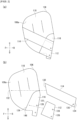
- FIGS. 1A and 1B are views illustrating an example of a side airbag device according to an embodiment of the present invention.
- FIG. 1A illustrates, from a right side in the vehicle width direction, or in other words, from the outside in the vehicle width direction (vehicle outer side), a side airbag device 100 and a vehicle left side seat 102 in which the side airbag device 100 is incorporated.
- the vehicle forward and back directions are illustrated with respective arrows F (forward) and B (back)
- left and right in the vehicle width direction are illustrated by respective arrows L (left) and R (right)
- the vehicle vertical direction is illustrated by respective arrows U (up) and D (down).
- the side airbag device 100 is installed inside a seat back 104 at the inner side in the vehicle width direction (vehicle inner side) of the seat 102 in the present embodiment.
- the side airbag device 100 is configured including an airbag cushion (cushion 106) that restrains the occupant and an inflator 108 that delivers gas to the cushion 106.
- the cushion 106 is wound or folded prior to operation, and is housed in a housing or such built into the side portion of the seat back 104 at the vehicle inner side.
- the cushion 106 in the housed state is covered with a seat cover, etc. and therefore is not visible from the outside.
- the inflator 108 is a gas generating device, and in the embodiments, a cylinder-shaped (cylindrical) inflator is adopted.
- the inflator 108 is contained in a rear part of a rear chamber 116 (described below) of the cushion 106, and is oriented so as to be longitudinal in the vertical direction along the seat back 104.
- the inflator 108 is electrically connected to the vehicle side, and when a signal originating from the detection of an impact from the vehicle side is received, the inflator 108 operates and supplies gas to the cushion 106.
- inflators that are currently used on a widespread basis include a type that is filled with a gas generating agent and combusts the agent to generate a gas, a type that supplies gas without generating heat by being filled with compressed gas, or a hybrid type that utilizes both combustion gas and compressed gas. Any type of inflator can be used as the inflator 108.
- the inflator 108 is provided with two stud bolts 110a and 110b separated in the longitudinal direction thereof.
- the stud bolts 110a and 110b are exposed to the outside by piercing through a base fabric of the cushion 106, and are fastened and fixed to a frame or the like of the seat back 104.
- the stud bolts 110a and 110b pierce through the cushion 106 and are fastened to the seat back 104, and thereby the cushion 106 is also attached to the seat back 104.
- FIG. 1B is a view illustrating a state after the cushion 106 of FIG. 1A is inflated and deployed.
- a sensor provided in the vehicle detects an impact, an operation signal is sent to the inflator 108, gas is discharged, and the cushion 106 uses the gas to exit the covering or the like of the seat cushion 106 and inflate and deploy into the cabin space.
- the cushion 106 inflates and deploys into an overall flat shape.
- the exterior surface of the cushion 106 is configured by a main panel 106a on the left side in the vehicle width direction and a main panel 106b on the right side in the vehicle width direction.
- the main panels 106a and 106b are made from a base fabric and are formed in an overall bag shape by sewing, adhesion, or the like.
- the cushion 106 can be formed by weaving using a One-Piece Woven (OPW) fabric or the like.
- OGW One-Piece Woven
- first tether 112 and second tether 114 are provided outside of the cushion 106 to suppress oscillation of the cushion 106.
- the configuration of the cushion 106 will be described further below with focus on the configuration and function of each tether.
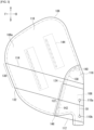
- FIGS. 2A and 2B are side views of the airbag cushion 106 of FIG. 1B .
- FIG. 2A illustrates a general overview of the cushion 106.
- the first tether 112 and the second tether 114 are bridged over the outside of the cushion 106.
- Each of these tethers is a cloth-like member, and for example, is formed from the same type of base fabric as the main panel 106a and such.
- the first tether 112 and the second tether 114 are both tensioned when the cushion 106 is inflated and deployed, and apply tension to the cushion 106 to thereby suppress oscillation of the cushion 106.
- FIG. 2B is a view with the first tether 112 and the second tether 114 removed from the cushion 106 of FIG. 2A . Prior to describing each tether, each portion of the cushion 106 will be described in detail.
- the interior of the cushion 106 is demarcated by a rear chamber 116 and a front chamber 118.
- the rear chamber 116 is a portion located at the base of the cushion 106, and is formed at a lower part of the vehicle back side.
- the rear chamber 116 has a vertically long shape along the seat back 104 (see FIG. 1B ).
- the rear chamber 116 is provided with two bolt holes 120 through which are passed stud bolts 110a and 110b in order to internally provide the inflator 108 (see FIG. 3 ) described above.
- the rear chamber 116 has a smaller capacity than the front chamber 118 and rapidly reaches a high pressure state immediately after operation of the inflator 108.
- the rear chamber 116 rapidly cleaves the covering of the seat back 104 and allows for quicker inflation and deployment of the overall cushion 106.
- the first tether 112 is provided outside of the rear chamber 116, and a front end 122 is connected to a front edge portion 124 of the rear chamber 116, and a rear end 126 is connected to a rear part of the rear chamber 116.
- the rear end 126 of the first tether 112 is provided with two bolt holes 128 and is anchored by two stud bolts 110a and 110b at the rear part of the rear chamber 116.
- the length of the first tether 112 from the front end 122 to the bolt hole 128 is shorter than a length in the vehicle front-back direction from the front edge portion 124 to the bolt hole 120 when the rear chamber 116 is expanded.
- This configuration allows the side airbag device 100 to efficiently tension the first tether 112.
- the first tether 112 is tensioned in association with the inflation and deployment of the rear chamber 116 to pull the front edge portion 124 of the rear chamber 116 to the rear of the vehicle, thereby suppressing oscillation of the rear chamber 116.
- the front chamber 118 is a portion that widely inflates and deploys forward and above from the rear chamber 116, and is formed abutting the front edge portion 124 of the rear chamber 116.
- the front chamber 118 is inflated and deployed from the seat back 104 to a range in which an occupant in a forward part of the vehicle is present, and actively restrains the occupant.
- the second tether 114 is provided outside of the front chamber 118 and the rear chamber 116, and a front end 130 is connected to a front edge portion 132 of the front chamber 118 and a rear end 134 is connected to the rear part of the rear chamber 116.
- the rear end 134 of the second tether 114 is provided with a bolt hole 136, and is anchored by one of the stud bolts 110a and 110b (for example, the stud bolt 110a) at the rear part of the rear chamber 116.
- the second tether 114 also has a length in the vehicle front-back direction extending from the front end 130 to the bolt hole 136 of the rear end 134 that is shorter than a length of a path in the vehicle front-back direction extending from the front edge portion 132 of the front chamber 118 to the bolt hole 120 when the inflated and deployed cushion 106 is expanded without being folded.
- This configuration allows the side airbag device 100 to efficiently tension the second tether 114.
- the second tether 114 is tensioned in association with the inflation and deployment of the front chamber 118 and the rear chamber 116 to primarily suppress oscillation of the front chamber 118.
- FIG. 3 is a detailed view of the airbag cushion 106 of FIG. 1A , and corresponds to FIG. 1B .
- a baffle 138 partitioning the rear chamber 116 and the front chamber 118 is provided inside the cushion 106.
- the baffle 138 is a wall-shaped portion formed using the same type of base fabric as the main panel 106a and the like, and is connected to the main panels 106a and 106b across the vehicle width direction.
- the baffle 138 is provided with a plurality of vent holes 140 and 142 and other features.
- the vent holes 140 and 142 are gas distribution ports through which gas passes from the rear chamber 116 side to the front chamber 118 side.
- An internal tether 144 is also provided in the cushion 106.
- the internal tether 144 is also formed using the same type of base fabric as the main panels 106a and 106b, is connected to the main panels 106a and 106b across the vehicle width direction, and regulates the width of the cushion 106 in the vehicle width direction.
- a predetermined outer vent (not illustrated) for discharging gas to the outside is also provided in a predetermined location of the cushion 106.
- the front end 122 of the first tether 112 can be also be similarly connected to the main panel 106a by sewing, for example, along a location of sewing the baffle 138 to the main panel 106a.
- the first tether 112 has a shape that is longer in the vertical direction than in the front-back direction, and in particular, the front end 122 is formed with a length that is equal to or greater than a distance D1 between the two stud bolts 110a and 110b.
- the first tether 112 is short in the vehicle front-back direction, and the front end 122 is also vertically long, and through such a configuration, the first tether 112 can apply a strong tension that pulls the rear chamber 116 to the rear of the vehicle in a wide vertical range, and can thereby suppress oscillation of the rear chamber 116.
- the front end 122 of the first tether 112 is connected to a range that includes at least a lower end 146 of the front edge portion 124 of the rear chamber 116.
- the cushion 106 as a whole inflates and deploys forward and diagonally upward because the inflator 108 is contained within a rearward lower part.
- the front end 122 of the first tether 112 supports the lower end 146 of the rear chamber 116, and thereby oscillation of the entire cushion 106 can be efficiently suppressed.
- FIG. 4 is an enlarged view near the rear chamber 116 of FIG. 3 .
- the front end 122 of the first tether 112 is connected to a range including locations P1 and P2 of the front edge portion 124 of the rear chamber 116, with the locations P1 and P2 being locations of the shortest distance to the stud bolts 110a and 110b.
- the first tether 112 By configuring the first tether 112 in this manner, the area between the stud bolts 110a and 110b and the front edge portion 124 of the rear chamber 116 is efficiently tensioned, and tension can be efficiently applied to the rear chamber 116 to suppress oscillation.
- the second tether 114 is configured to be longer in the front-back direction than in the vertical direction. Through such a configuration, the second tether 114 extends from the stud bolt 110a to the front edge portion 132 of the front chamber 118 and can prevent oscillation of the front chamber 118.
- the range of connection between the front end 130 of the second tether 114 and the front edge portion 132 of the front chamber 118 is sewn in a much longer range than the range in which the rear end 134 of the second tether 114 connects to the rear part of the rear chamber 116 (the range through which the stud bolt 110a penetrates).
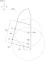
- FIGS. 5A and 5B are views illustrating the conditions when the airbag cushion 106 of FIG. 1A is inflated and deployed.
- FIG. 5A is a view of the cushion 106 from the vehicle outer side, and illustrates with a virtual line the movement of a cushion 10 in the vehicle front-back direction.
- the conventional cushion 10 may tilt forward or reactively tilt backwards due to the pressure of gas supplied from the inflator.
- the cushion 106 of the present embodiment however is tensioned by the first tether 112, and thereby the rear chamber 116 is supported.
- the rear chamber 116 is a portion that contains the inflator 108 (see FIG. 3 , etc.) and is positioned at the base of the entire cushion 106.
- the rear chamber 116 is also small in capacity and quickly reaches a high pressure state immediately after operation of the inflator 108.
- the first tether 112 is also rapidly and strongly tensioned.
- the rear chamber 116 at the base of the cushion 106 is supported with strong tension by the first tether 112, and thereby oscillation in the front-back direction of the overall cushion 106 is prevented, and the restraint performance of the cushion 106 can be increased.
- FIG. 5B is a schematic view of the cushion 106 as viewed from above, and illustrates with a virtual line the movement of the cushion 10 in the vehicle width direction.
- the conventional cushion 10 may also oscillate in the vehicle width direction due to the pressure of the gas.
- the second tether 114 in addition to the first tether 112 described above, the second tether 114 is tensioned and applies tension to the front chamber 118 to pull the front chamber 118 toward the rear of the vehicle. Accordingly, oscillation of the cushion 106 in the vehicle width direction, and in particular, oscillation in the vehicle width direction originating at the boundary line between the front chamber 118 and the rear chamber 116 can be prevented.
- the side airbag device 100 of the present embodiment can efficiently suppress oscillation of the cushion 106 and improve the restraint performance of the cushion 106 through use of the first tether 112 and the second tether 114.
- the first tether 112 and the second tether 114 are both provided at the occupant side of the cushion 106 in the present embodiment, the tethers thereof may also be provided at the side opposite the occupant, or one may be provided at the occupant side and the other provided at the side opposite the occupant.
- the cushion 106 is provided at the vehicle inner side of the seat back 108. Because there is no support structure for the cushion 106, such as a side door, at the vehicle inner side of the seat back 108, the first tether 112 and the second tether 114, which suppress oscillation, function more favorably. However, the cushion 106 may of course be provided at the vehicle outer side of the seat back 108, and in that case, the first tether 112 and the second tether 114 suppress oscillation, thereby improving the restraint performance of the cushion 106.
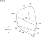
- FIG. 6 is a view illustrating a modified example of the second tether 114 (second tether 200) of FIG. 2 .
- the second tether 114 is shaped in the form of a band with upper and lower sides that are nearly parallel, while the second tether 200 is shaped such that the vertical width of a front end 202 is wider than a vertical width of a rear end 204, with an upper side 206 and a lower side 208 spread out in a non-parallel manner from the rear end 204 to the front end 202.
- the second tether 200 of this configuration also allows the front end 202 to be sewn to the front edge portion 132 of the front chamber 118 in a longer range compared to the rear end 204, to thereby efficiently pull the front edge portion 132 toward the rear end 204 side and prevent oscillation of the cushion 106.
- the second tether 114 of FIG. 2 and the second tether 200 of FIG. 6 are both illustrated as polygonal shapes in the drawings, the second tether is not limited to such a shape, and for example, the function of pulling the front chamber 118 toward the back side can be achieved even with a rounded shape such as an oval not having an angle in the contour. Even with a second tether having such a shape, the front chamber 118 can be efficiently pulled to the rearward side and oscillation of the cushion 106 can be suppressed by connecting the front end side of the second tether to the front edge portion 132 of the front chamber 118 in a range that is longer than the width on the rear end side.
- the present invention can be used in a side airbag device that restrains a vehicle occupant from a side.
Landscapes
- Engineering & Computer Science (AREA)
- Mechanical Engineering (AREA)
- Aviation & Aerospace Engineering (AREA)
- Transportation (AREA)
- Air Bags (AREA)
- Physics & Mathematics (AREA)
- Fluid Mechanics (AREA)
Claims (3)
- Seitenairbagvorrichtung (100), umfassend:eine vertikal lange hintere Kammer (116), die sich von einem Seitenabschnitt eines Fahrzeugsitzes (102) aufbläst und entfaltet;eine vordere Kammer (118), die an einen vorderen Randabschnitt der hinteren Kammer (124) angrenzt und sich von der hinteren Kammer (116) nach vorne und nach oben aufbläst und entfaltet;einen vertikal langen Gasgenerator (108), der innerhalb eines hinteren Teils der hinteren Kammer (116) enthalten ist; undeinen tuchartigen ersten Haltegurt (112), der außerhalb der hinteren Kammer (116) bereitgestellt ist, ein vorderes Ende (122), das mit dem vorderen Randabschnitt der hinteren Kammer (124) verbunden ist, und ein hinteres Ende (126), das mit dem hinteren Teil der hinteren Kammer (116) verbunden ist, aufweist und gespannt ist, wenn die hintere Kammer (116) aufgeblasen und entfaltet ist;wobei:die hintere Kammer (116) eine geringere Kapazität als die vordere Kammer (118) aufweist; wobeider erste Haltegurt (112) in einer vertikalen Richtung länger als in einer Vorwärts-Rückwärts-Richtung ist, und das vordere Ende (122) des ersten Haltegurts (112) mit einem Bereich verbunden ist, der mindestens ein unteres Ende des vorderen Randabschnitts der hinteren Kammer (116) einschließt;die Seitenairbagvorrichtung (100) ferner umfassend zwei Stehbolzen (110a, 110b), die längs beabstandet an dem Gasgenerator (108) bereitgestellt, von der hinteren Kammer (116) freigelegt und konfiguriert sind, um an dem Fahrzeugsitz (102) befestigt zu werden;wobei das hintere Ende des ersten Haltegurts (112) über die zwei Stehbolzen (110a, 110b) an dem hinteren Teil der hinteren Kammer (116) verankert ist unddas vordere Ende des ersten Haltegurts (112) eine Länge aufweist, die größer als oder gleich einer Entfernung zwischen den zwei Stehbolzen (110a, 110b) ist, unddas vordere Ende des ersten Haltegurts (112) mit einem Bereich des vorderen Randabschnitts der hinteren Kammer (116) verbunden ist, wobei der Bereich eine Stelle der kürzesten Entfernung zu den Stehbolzen (110a, 110b) einschließt; dadurch gekennzeichnet, dassein tuchartiger zweiter Haltegurt (114), der außerhalb der vorderen Kammer (118) und der hinteren Kammer (116) bereitgestellt ist, ein vorderes Ende (130), das mit einem vorderen Randabschnitt der vorderen Kammer (132) verbunden ist, und ein hinteres Ende, das mit einem hinteren Teil der hinteren Kammer (116) verbunden ist, aufweist und gespannt ist, wenn die hintere Kammer (116) aufgeblasen und entfaltet ist, wobeidas hintere Ende des zweiten Haltegurts (114) durch mindestens einen der zwei Stehbolzen (110a, 110b) an dem hinteren Teil der hinteren Kammer (116) verankert ist, wobeider zweite Haltegurt (114) in der Vorwärts-Rückwärts-Richtung länger als in der vertikalen Richtung ist.
- Seitenairbagvorrichtung (100) nach Anspruch 1, wobei das vordere Ende des zweiten Haltegurts (114) mit einem vorderen Randabschnitt der vorderen Kammer (132) in einem Bereich verbunden ist, der länger als ein Bereich ist, in dem das hintere Ende des zweiten Haltegurts (114) mit dem hinteren Teil der hinteren Kammer (116) verbunden ist.
- Seitenairbagvorrichtung (100) nach einem der Ansprüche 1 oder 2, wobei eine Länge von dem vorderen Ende zu dem hinteren Ende des zweiten Haltegurts (114) kürzer als eine Länge eines Pfads ist, der sich von dem vorderen Randabschnitt der vorderen Kammer (132) zu dem hinteren Teil der hinteren Kammer (116) erstreckt, wenn die vordere Kammer (118) und die hintere Kammer (116) aufgeblasen und ohne Biegen entfaltet sind.
Applications Claiming Priority (2)
| Application Number | Priority Date | Filing Date | Title |
|---|---|---|---|
| JP2017097841 | 2017-05-17 | ||
| PCT/JP2018/017817 WO2018212021A1 (ja) | 2017-05-17 | 2018-05-08 | サイドエアバッグ装置 |
Publications (3)
| Publication Number | Publication Date |
|---|---|
| EP3626547A1 EP3626547A1 (de) | 2020-03-25 |
| EP3626547A4 EP3626547A4 (de) | 2020-11-11 |
| EP3626547B1 true EP3626547B1 (de) | 2024-10-09 |
Family
ID=64273759
Family Applications (1)
| Application Number | Title | Priority Date | Filing Date |
|---|---|---|---|
| EP18801397.3A Active EP3626547B1 (de) | 2017-05-17 | 2018-05-08 | Seitenairbagvorrichtung |
Country Status (6)
| Country | Link |
|---|---|
| US (1) | US11104292B2 (de) |
| EP (1) | EP3626547B1 (de) |
| JP (1) | JP6852154B2 (de) |
| KR (2) | KR102373395B1 (de) |
| CN (2) | CN110603174A (de) |
| WO (1) | WO2018212021A1 (de) |
Families Citing this family (9)
| Publication number | Priority date | Publication date | Assignee | Title |
|---|---|---|---|---|
| US11865996B2 (en) * | 2018-03-01 | 2024-01-09 | ZF Passive Safety Systems US Inc. | Seat-mounted occupant restraint system |
| EP3848253B1 (de) * | 2018-09-05 | 2023-08-30 | Autoliv Development AB | Seitenairbagvorrichtung |
| JP7533104B2 (ja) * | 2020-10-13 | 2024-08-14 | マツダ株式会社 | サイドエアバッグ装置及び、これを備えた車両用シート |
| KR102928634B1 (ko) * | 2021-01-18 | 2026-02-19 | 현대모비스 주식회사 | 사이드 에어백 |
| CN113002473B (zh) * | 2021-04-16 | 2022-08-02 | 宁波均胜汽车安全系统有限公司 | 一种气囊装置 |
| JP7494807B2 (ja) * | 2021-06-17 | 2024-06-04 | 豊田合成株式会社 | ファーサイドエアバッグ装置 |
| TWI862951B (zh) * | 2021-11-21 | 2024-11-21 | 奇景光電股份有限公司 | 以供應用於觸控面板之旋鈕使用的校正方法以及校正裝置 |
| JP7819657B2 (ja) * | 2023-03-08 | 2026-02-25 | トヨタ自動車株式会社 | 車両用センターエアバッグ装置 |
| JP7697989B2 (ja) * | 2023-05-30 | 2025-06-24 | ダイハツ工業株式会社 | 力布構造 |
Citations (1)
| Publication number | Priority date | Publication date | Assignee | Title |
|---|---|---|---|---|
| WO2015198739A1 (ja) * | 2014-06-24 | 2015-12-30 | オートリブ ディベロップメント エービー | サイドエアバッグ装置 |
Family Cites Families (20)
| Publication number | Priority date | Publication date | Assignee | Title |
|---|---|---|---|---|
| CN101223057A (zh) * | 2005-11-10 | 2008-07-16 | 高田株式会社 | 气囊及气囊装置 |
| US7770921B2 (en) * | 2007-05-25 | 2010-08-10 | Autoliv Development Ab | Airbag for protection of a vehicle occupant |
| US8047564B2 (en) | 2009-09-02 | 2011-11-01 | Tk Holdings Inc. | Airbag |
| US8360469B2 (en) * | 2010-08-27 | 2013-01-29 | Tk Holdings Inc. | Airbag system |
| CN104349945B (zh) * | 2012-06-06 | 2016-11-09 | 丰田自动车株式会社 | 车辆用侧面安全气囊装置 |
| RU2587189C1 (ru) * | 2012-07-19 | 2016-06-20 | Тойота Дзидося Кабусики Кайся | Устройство боковой подушки безопасности автомобиля |
| JP2014133462A (ja) * | 2013-01-09 | 2014-07-24 | Toyota Motor Corp | 車両用サイドエアバッグ装置 |
| JP6067490B2 (ja) * | 2013-06-10 | 2017-01-25 | 豊田合成株式会社 | サイドエアバッグ装置 |
| JP5696748B2 (ja) * | 2013-07-31 | 2015-04-08 | トヨタ自動車株式会社 | 車両用サイドエアバッグ装置及び車両用シート |
| KR101718677B1 (ko) | 2014-04-14 | 2017-03-21 | 미쓰비시덴키 가부시키가이샤 | 제어 장치 및 레이저 가공 장치 |
| DE112015002103T5 (de) * | 2014-05-01 | 2017-03-02 | Tk Holdings Inc. | Mittiges Seitenaufprallairbagmodul mit Steuerhalteband |
| JP6179469B2 (ja) | 2014-06-23 | 2017-08-16 | トヨタ自動車株式会社 | ファーサイドエアバッグ装置 |
| EP2979933B1 (de) * | 2014-07-29 | 2018-06-20 | Toyoda Gosei Co., Ltd. | Airbagvorrichtung auf der gegenüberliegenden seite |
| JP6115542B2 (ja) * | 2014-10-10 | 2017-04-19 | トヨタ自動車株式会社 | 車両用サイドエアバッグ装置 |
| JP6428141B2 (ja) * | 2014-10-17 | 2018-11-28 | 三菱自動車工業株式会社 | サイドエアバッグ装置 |
| JP6327110B2 (ja) | 2014-10-23 | 2018-05-23 | 豊田合成株式会社 | 側突用エアバッグ装置 |
| JP6052266B2 (ja) * | 2014-10-27 | 2016-12-27 | トヨタ自動車株式会社 | 車両用サイドエアバッグ装置及びサイドエアバッグの製造方法 |
| JP6131935B2 (ja) * | 2014-12-03 | 2017-05-24 | トヨタ自動車株式会社 | 車両用ファーサイドエアバッグ装置 |
| JP6451597B2 (ja) * | 2015-11-06 | 2019-01-16 | トヨタ自動車株式会社 | 運転席用エアバッグ装置 |
| JP6658585B2 (ja) * | 2017-02-03 | 2020-03-04 | トヨタ自動車株式会社 | サイドエアバッグ装置を搭載した車両用シート |
-
2018
- 2018-05-08 KR KR1020197035410A patent/KR102373395B1/ko active Active
- 2018-05-08 CN CN201880029148.4A patent/CN110603174A/zh active Pending
- 2018-05-08 US US16/613,890 patent/US11104292B2/en active Active
- 2018-05-08 CN CN202510950389.4A patent/CN120716631A/zh active Pending
- 2018-05-08 KR KR1020227005286A patent/KR20220025281A/ko not_active Abandoned
- 2018-05-08 EP EP18801397.3A patent/EP3626547B1/de active Active
- 2018-05-08 WO PCT/JP2018/017817 patent/WO2018212021A1/ja not_active Ceased
- 2018-05-08 JP JP2019519188A patent/JP6852154B2/ja active Active
Patent Citations (1)
| Publication number | Priority date | Publication date | Assignee | Title |
|---|---|---|---|---|
| WO2015198739A1 (ja) * | 2014-06-24 | 2015-12-30 | オートリブ ディベロップメント エービー | サイドエアバッグ装置 |
Also Published As
| Publication number | Publication date |
|---|---|
| EP3626547A4 (de) | 2020-11-11 |
| CN120716631A (zh) | 2025-09-30 |
| JPWO2018212021A1 (ja) | 2020-01-16 |
| US20210024030A1 (en) | 2021-01-28 |
| KR102373395B1 (ko) | 2022-03-11 |
| US11104292B2 (en) | 2021-08-31 |
| KR20200003118A (ko) | 2020-01-08 |
| EP3626547A1 (de) | 2020-03-25 |
| JP6852154B2 (ja) | 2021-03-31 |
| WO2018212021A1 (ja) | 2018-11-22 |
| CN110603174A (zh) | 2019-12-20 |
| KR20220025281A (ko) | 2022-03-03 |
Similar Documents
| Publication | Publication Date | Title |
|---|---|---|
| EP3626547B1 (de) | Seitenairbagvorrichtung | |
| JP5595154B2 (ja) | カーテンエアバッグ | |
| US10214172B2 (en) | Vehicle side airbag device | |
| EP3604047B1 (de) | Passagierschutzvorrichtung | |
| EP3521109B1 (de) | Seitenairbagvorrichtung | |
| CN109963754B (zh) | 侧气囊装置 | |
| JP6450855B2 (ja) | サイドエアバッグ装置 | |
| CN112061070B (zh) | 侧面安全气囊装置 | |
| US10017145B2 (en) | Side airbag apparatus | |
| EP3848253B1 (de) | Seitenairbagvorrichtung | |
| JP6185653B2 (ja) | カーテンエアバッグ装置 | |
| US12097820B1 (en) | Airbag with extendable member | |
| JP6372041B2 (ja) | サイドエアバッグ装置 | |
| JP2015189459A (ja) | サイドエアバッグ装置 | |
| JP2005271755A (ja) | 頭部保護エアバッグ装置 | |
| JP6111227B2 (ja) | エアバッグ装置 | |
| US11472366B2 (en) | Head protection airbag device | |
| US11772595B2 (en) | Airbag with reinforced tether | |
| JP2015013608A (ja) | カーテンエアバッグ装置 |
Legal Events
| Date | Code | Title | Description |
|---|---|---|---|
| STAA | Information on the status of an ep patent application or granted ep patent |
Free format text: STATUS: THE INTERNATIONAL PUBLICATION HAS BEEN MADE |
|
| PUAI | Public reference made under article 153(3) epc to a published international application that has entered the european phase |
Free format text: ORIGINAL CODE: 0009012 |
|
| STAA | Information on the status of an ep patent application or granted ep patent |
Free format text: STATUS: REQUEST FOR EXAMINATION WAS MADE |
|
| 17P | Request for examination filed |
Effective date: 20191213 |
|
| AK | Designated contracting states |
Kind code of ref document: A1 Designated state(s): AL AT BE BG CH CY CZ DE DK EE ES FI FR GB GR HR HU IE IS IT LI LT LU LV MC MK MT NL NO PL PT RO RS SE SI SK SM TR |
|
| AX | Request for extension of the european patent |
Extension state: BA ME |
|
| DAV | Request for validation of the european patent (deleted) | ||
| DAX | Request for extension of the european patent (deleted) | ||
| A4 | Supplementary search report drawn up and despatched |
Effective date: 20201014 |
|
| RIC1 | Information provided on ipc code assigned before grant |
Ipc: B60R 21/207 20060101ALI20201008BHEP Ipc: B60R 21/2338 20110101AFI20201008BHEP Ipc: B60N 2/64 20060101ALI20201008BHEP Ipc: B60R 21/233 20060101ALI20201008BHEP Ipc: B60N 2/427 20060101ALI20201008BHEP |
|
| STAA | Information on the status of an ep patent application or granted ep patent |
Free format text: STATUS: EXAMINATION IS IN PROGRESS |
|
| 17Q | First examination report despatched |
Effective date: 20210707 |
|
| GRAP | Despatch of communication of intention to grant a patent |
Free format text: ORIGINAL CODE: EPIDOSNIGR1 |
|
| STAA | Information on the status of an ep patent application or granted ep patent |
Free format text: STATUS: GRANT OF PATENT IS INTENDED |
|
| INTG | Intention to grant announced |
Effective date: 20240507 |
|
| GRAS | Grant fee paid |
Free format text: ORIGINAL CODE: EPIDOSNIGR3 |
|
| GRAA | (expected) grant |
Free format text: ORIGINAL CODE: 0009210 |
|
| STAA | Information on the status of an ep patent application or granted ep patent |
Free format text: STATUS: THE PATENT HAS BEEN GRANTED |
|
| AK | Designated contracting states |
Kind code of ref document: B1 Designated state(s): AL AT BE BG CH CY CZ DE DK EE ES FI FR GB GR HR HU IE IS IT LI LT LU LV MC MK MT NL NO PL PT RO RS SE SI SK SM TR |
|
| REG | Reference to a national code |
Ref country code: CH Ref legal event code: EP |
|
| REG | Reference to a national code |
Ref country code: DE Ref legal event code: R096 Ref document number: 602018075256 Country of ref document: DE |
|
| REG | Reference to a national code |
Ref country code: IE Ref legal event code: FG4D |
|
| REG | Reference to a national code |
Ref country code: LT Ref legal event code: MG9D |
|
| REG | Reference to a national code |
Ref country code: NL Ref legal event code: MP Effective date: 20241009 |
|
| REG | Reference to a national code |
Ref country code: AT Ref legal event code: MK05 Ref document number: 1730279 Country of ref document: AT Kind code of ref document: T Effective date: 20241009 |
|
| PG25 | Lapsed in a contracting state [announced via postgrant information from national office to epo] |
Ref country code: NL Free format text: LAPSE BECAUSE OF FAILURE TO SUBMIT A TRANSLATION OF THE DESCRIPTION OR TO PAY THE FEE WITHIN THE PRESCRIBED TIME-LIMIT Effective date: 20241009 |
|
| PG25 | Lapsed in a contracting state [announced via postgrant information from national office to epo] |
Ref country code: NL Free format text: LAPSE BECAUSE OF FAILURE TO SUBMIT A TRANSLATION OF THE DESCRIPTION OR TO PAY THE FEE WITHIN THE PRESCRIBED TIME-LIMIT Effective date: 20241009 |
|
| PG25 | Lapsed in a contracting state [announced via postgrant information from national office to epo] |
Ref country code: IS Free format text: LAPSE BECAUSE OF FAILURE TO SUBMIT A TRANSLATION OF THE DESCRIPTION OR TO PAY THE FEE WITHIN THE PRESCRIBED TIME-LIMIT Effective date: 20250209 Ref country code: PT Free format text: LAPSE BECAUSE OF FAILURE TO SUBMIT A TRANSLATION OF THE DESCRIPTION OR TO PAY THE FEE WITHIN THE PRESCRIBED TIME-LIMIT Effective date: 20250210 Ref country code: HR Free format text: LAPSE BECAUSE OF FAILURE TO SUBMIT A TRANSLATION OF THE DESCRIPTION OR TO PAY THE FEE WITHIN THE PRESCRIBED TIME-LIMIT Effective date: 20241009 |
|
| PG25 | Lapsed in a contracting state [announced via postgrant information from national office to epo] |
Ref country code: FI Free format text: LAPSE BECAUSE OF FAILURE TO SUBMIT A TRANSLATION OF THE DESCRIPTION OR TO PAY THE FEE WITHIN THE PRESCRIBED TIME-LIMIT Effective date: 20241009 |
|
| PG25 | Lapsed in a contracting state [announced via postgrant information from national office to epo] |
Ref country code: BG Free format text: LAPSE BECAUSE OF FAILURE TO SUBMIT A TRANSLATION OF THE DESCRIPTION OR TO PAY THE FEE WITHIN THE PRESCRIBED TIME-LIMIT Effective date: 20241009 |
|
| PG25 | Lapsed in a contracting state [announced via postgrant information from national office to epo] |
Ref country code: ES Free format text: LAPSE BECAUSE OF FAILURE TO SUBMIT A TRANSLATION OF THE DESCRIPTION OR TO PAY THE FEE WITHIN THE PRESCRIBED TIME-LIMIT Effective date: 20241009 |
|
| PG25 | Lapsed in a contracting state [announced via postgrant information from national office to epo] |
Ref country code: NO Free format text: LAPSE BECAUSE OF FAILURE TO SUBMIT A TRANSLATION OF THE DESCRIPTION OR TO PAY THE FEE WITHIN THE PRESCRIBED TIME-LIMIT Effective date: 20250109 |
|
| PG25 | Lapsed in a contracting state [announced via postgrant information from national office to epo] |
Ref country code: LV Free format text: LAPSE BECAUSE OF FAILURE TO SUBMIT A TRANSLATION OF THE DESCRIPTION OR TO PAY THE FEE WITHIN THE PRESCRIBED TIME-LIMIT Effective date: 20241009 Ref country code: GR Free format text: LAPSE BECAUSE OF FAILURE TO SUBMIT A TRANSLATION OF THE DESCRIPTION OR TO PAY THE FEE WITHIN THE PRESCRIBED TIME-LIMIT Effective date: 20250110 Ref country code: AT Free format text: LAPSE BECAUSE OF FAILURE TO SUBMIT A TRANSLATION OF THE DESCRIPTION OR TO PAY THE FEE WITHIN THE PRESCRIBED TIME-LIMIT Effective date: 20241009 |
|
| PG25 | Lapsed in a contracting state [announced via postgrant information from national office to epo] |
Ref country code: PL Free format text: LAPSE BECAUSE OF FAILURE TO SUBMIT A TRANSLATION OF THE DESCRIPTION OR TO PAY THE FEE WITHIN THE PRESCRIBED TIME-LIMIT Effective date: 20241009 |
|
| PG25 | Lapsed in a contracting state [announced via postgrant information from national office to epo] |
Ref country code: RS Free format text: LAPSE BECAUSE OF FAILURE TO SUBMIT A TRANSLATION OF THE DESCRIPTION OR TO PAY THE FEE WITHIN THE PRESCRIBED TIME-LIMIT Effective date: 20250109 |
|
| PG25 | Lapsed in a contracting state [announced via postgrant information from national office to epo] |
Ref country code: SM Free format text: LAPSE BECAUSE OF FAILURE TO SUBMIT A TRANSLATION OF THE DESCRIPTION OR TO PAY THE FEE WITHIN THE PRESCRIBED TIME-LIMIT Effective date: 20241009 |
|
| PGFP | Annual fee paid to national office [announced via postgrant information from national office to epo] |
Ref country code: DE Payment date: 20250528 Year of fee payment: 8 |
|
| PG25 | Lapsed in a contracting state [announced via postgrant information from national office to epo] |
Ref country code: DK Free format text: LAPSE BECAUSE OF FAILURE TO SUBMIT A TRANSLATION OF THE DESCRIPTION OR TO PAY THE FEE WITHIN THE PRESCRIBED TIME-LIMIT Effective date: 20241009 |
|
| PGFP | Annual fee paid to national office [announced via postgrant information from national office to epo] |
Ref country code: GB Payment date: 20250520 Year of fee payment: 8 |
|
| REG | Reference to a national code |
Ref country code: DE Ref legal event code: R097 Ref document number: 602018075256 Country of ref document: DE |
|
| PG25 | Lapsed in a contracting state [announced via postgrant information from national office to epo] |
Ref country code: EE Free format text: LAPSE BECAUSE OF FAILURE TO SUBMIT A TRANSLATION OF THE DESCRIPTION OR TO PAY THE FEE WITHIN THE PRESCRIBED TIME-LIMIT Effective date: 20241009 |
|
| PGFP | Annual fee paid to national office [announced via postgrant information from national office to epo] |
Ref country code: FR Payment date: 20250526 Year of fee payment: 8 |
|
| PG25 | Lapsed in a contracting state [announced via postgrant information from national office to epo] |
Ref country code: RO Free format text: LAPSE BECAUSE OF FAILURE TO SUBMIT A TRANSLATION OF THE DESCRIPTION OR TO PAY THE FEE WITHIN THE PRESCRIBED TIME-LIMIT Effective date: 20241009 |
|
| PG25 | Lapsed in a contracting state [announced via postgrant information from national office to epo] |
Ref country code: SK Free format text: LAPSE BECAUSE OF FAILURE TO SUBMIT A TRANSLATION OF THE DESCRIPTION OR TO PAY THE FEE WITHIN THE PRESCRIBED TIME-LIMIT Effective date: 20241009 |
|
| PG25 | Lapsed in a contracting state [announced via postgrant information from national office to epo] |
Ref country code: CZ Free format text: LAPSE BECAUSE OF FAILURE TO SUBMIT A TRANSLATION OF THE DESCRIPTION OR TO PAY THE FEE WITHIN THE PRESCRIBED TIME-LIMIT Effective date: 20241009 |
|
| PG25 | Lapsed in a contracting state [announced via postgrant information from national office to epo] |
Ref country code: IT Free format text: LAPSE BECAUSE OF FAILURE TO SUBMIT A TRANSLATION OF THE DESCRIPTION OR TO PAY THE FEE WITHIN THE PRESCRIBED TIME-LIMIT Effective date: 20241009 |
|
| PLBE | No opposition filed within time limit |
Free format text: ORIGINAL CODE: 0009261 |
|
| STAA | Information on the status of an ep patent application or granted ep patent |
Free format text: STATUS: NO OPPOSITION FILED WITHIN TIME LIMIT |
|
| PG25 | Lapsed in a contracting state [announced via postgrant information from national office to epo] |
Ref country code: SE Free format text: LAPSE BECAUSE OF FAILURE TO SUBMIT A TRANSLATION OF THE DESCRIPTION OR TO PAY THE FEE WITHIN THE PRESCRIBED TIME-LIMIT Effective date: 20241009 |
|
| 26N | No opposition filed |
Effective date: 20250710 |
|
| REG | Reference to a national code |
Ref country code: CH Ref legal event code: H13 Free format text: ST27 STATUS EVENT CODE: U-0-0-H10-H13 (AS PROVIDED BY THE NATIONAL OFFICE) Effective date: 20251223 |
|
| PG25 | Lapsed in a contracting state [announced via postgrant information from national office to epo] |
Ref country code: LU Free format text: LAPSE BECAUSE OF NON-PAYMENT OF DUE FEES Effective date: 20250508 |
|
| PG25 | Lapsed in a contracting state [announced via postgrant information from national office to epo] |
Ref country code: CH Free format text: LAPSE BECAUSE OF NON-PAYMENT OF DUE FEES Effective date: 20250531 |
|
| REG | Reference to a national code |
Ref country code: BE Ref legal event code: MM Effective date: 20250531 |
|
| PG25 | Lapsed in a contracting state [announced via postgrant information from national office to epo] |
Ref country code: MC Free format text: LAPSE BECAUSE OF FAILURE TO SUBMIT A TRANSLATION OF THE DESCRIPTION OR TO PAY THE FEE WITHIN THE PRESCRIBED TIME-LIMIT Effective date: 20241009 |
|
| PG25 | Lapsed in a contracting state [announced via postgrant information from national office to epo] |
Ref country code: IE Free format text: LAPSE BECAUSE OF NON-PAYMENT OF DUE FEES Effective date: 20250508 |
|
| PG25 | Lapsed in a contracting state [announced via postgrant information from national office to epo] |
Ref country code: BE Free format text: LAPSE BECAUSE OF NON-PAYMENT OF DUE FEES Effective date: 20250531 |