EP3626548A1 - Verfahren zum ver- und/oder entriegeln eines elektrofahrzeugs und zugehörige vorrichtung - Google Patents
Verfahren zum ver- und/oder entriegeln eines elektrofahrzeugs und zugehörige vorrichtung Download PDFInfo
- Publication number
- EP3626548A1 EP3626548A1 EP19197675.2A EP19197675A EP3626548A1 EP 3626548 A1 EP3626548 A1 EP 3626548A1 EP 19197675 A EP19197675 A EP 19197675A EP 3626548 A1 EP3626548 A1 EP 3626548A1
- Authority
- EP
- European Patent Office
- Prior art keywords
- vehicle
- mobile device
- signal
- user
- component
- Prior art date
- Legal status (The legal status is an assumption and is not a legal conclusion. Google has not performed a legal analysis and makes no representation as to the accuracy of the status listed.)
- Granted
Links
Images




Classifications
-
- E—FIXED CONSTRUCTIONS
- E05—LOCKS; KEYS; WINDOW OR DOOR FITTINGS; SAFES
- E05B—LOCKS; ACCESSORIES THEREFOR; HANDCUFFS
- E05B85/00—Details of vehicle locks not provided for in groups E05B77/00 - E05B83/00
-
- B—PERFORMING OPERATIONS; TRANSPORTING
- B60—VEHICLES IN GENERAL
- B60R—VEHICLES, VEHICLE FITTINGS, OR VEHICLE PARTS, NOT OTHERWISE PROVIDED FOR
- B60R25/00—Fittings or systems for preventing or indicating unauthorised use or theft of vehicles
- B60R25/20—Means to switch the anti-theft system on or off
- B60R25/24—Means to switch the anti-theft system on or off using electronic identifiers containing a code not memorised by the user
- B60R25/245—Means to switch the anti-theft system on or off using electronic identifiers containing a code not memorised by the user where the antenna reception area plays a role
-
- B—PERFORMING OPERATIONS; TRANSPORTING
- B60—VEHICLES IN GENERAL
- B60R—VEHICLES, VEHICLE FITTINGS, OR VEHICLE PARTS, NOT OTHERWISE PROVIDED FOR
- B60R25/00—Fittings or systems for preventing or indicating unauthorised use or theft of vehicles
- B60R25/20—Means to switch the anti-theft system on or off
- B60R25/24—Means to switch the anti-theft system on or off using electronic identifiers containing a code not memorised by the user
-
- B—PERFORMING OPERATIONS; TRANSPORTING
- B60—VEHICLES IN GENERAL
- B60R—VEHICLES, VEHICLE FITTINGS, OR VEHICLE PARTS, NOT OTHERWISE PROVIDED FOR
- B60R25/00—Fittings or systems for preventing or indicating unauthorised use or theft of vehicles
- B60R25/30—Detection related to theft or to other events relevant to anti-theft systems
- B60R25/34—Detection related to theft or to other events relevant to anti-theft systems of conditions of vehicle components, e.g. of windows, door locks or gear selectors
-
- B—PERFORMING OPERATIONS; TRANSPORTING
- B60—VEHICLES IN GENERAL
- B60K—ARRANGEMENT OR MOUNTING OF PROPULSION UNITS OR OF TRANSMISSIONS IN VEHICLES; ARRANGEMENT OR MOUNTING OF PLURAL DIVERSE PRIME-MOVERS IN VEHICLES; AUXILIARY DRIVES FOR VEHICLES; INSTRUMENTATION OR DASHBOARDS FOR VEHICLES; ARRANGEMENTS IN CONNECTION WITH COOLING, AIR INTAKE, GAS EXHAUST OR FUEL SUPPLY OF PROPULSION UNITS IN VEHICLES
- B60K35/00—Instruments specially adapted for vehicles; Arrangement of instruments in or on vehicles
- B60K35/20—Output arrangements, i.e. from vehicle to user, associated with vehicle functions or specially adapted therefor
- B60K35/21—Output arrangements, i.e. from vehicle to user, associated with vehicle functions or specially adapted therefor using visual output, e.g. blinking lights or matrix displays
- B60K35/22—Display screens
-
- B—PERFORMING OPERATIONS; TRANSPORTING
- B60—VEHICLES IN GENERAL
- B60R—VEHICLES, VEHICLE FITTINGS, OR VEHICLE PARTS, NOT OTHERWISE PROVIDED FOR
- B60R25/00—Fittings or systems for preventing or indicating unauthorised use or theft of vehicles
- B60R25/01—Fittings or systems for preventing or indicating unauthorised use or theft of vehicles operating on vehicle systems or fittings, e.g. on doors, seats or windscreens
- B60R25/04—Fittings or systems for preventing or indicating unauthorised use or theft of vehicles operating on vehicle systems or fittings, e.g. on doors, seats or windscreens operating on the propulsion system, e.g. engine or drive motor
-
- B—PERFORMING OPERATIONS; TRANSPORTING
- B60—VEHICLES IN GENERAL
- B60R—VEHICLES, VEHICLE FITTINGS, OR VEHICLE PARTS, NOT OTHERWISE PROVIDED FOR
- B60R25/00—Fittings or systems for preventing or indicating unauthorised use or theft of vehicles
- B60R25/01—Fittings or systems for preventing or indicating unauthorised use or theft of vehicles operating on vehicle systems or fittings, e.g. on doors, seats or windscreens
- B60R25/04—Fittings or systems for preventing or indicating unauthorised use or theft of vehicles operating on vehicle systems or fittings, e.g. on doors, seats or windscreens operating on the propulsion system, e.g. engine or drive motor
- B60R25/045—Fittings or systems for preventing or indicating unauthorised use or theft of vehicles operating on vehicle systems or fittings, e.g. on doors, seats or windscreens operating on the propulsion system, e.g. engine or drive motor by limiting or cutting the electrical supply to the propulsion unit
-
- B—PERFORMING OPERATIONS; TRANSPORTING
- B60—VEHICLES IN GENERAL
- B60R—VEHICLES, VEHICLE FITTINGS, OR VEHICLE PARTS, NOT OTHERWISE PROVIDED FOR
- B60R25/00—Fittings or systems for preventing or indicating unauthorised use or theft of vehicles
- B60R25/10—Fittings or systems for preventing or indicating unauthorised use or theft of vehicles actuating a signalling device
- B60R25/104—Fittings or systems for preventing or indicating unauthorised use or theft of vehicles actuating a signalling device characterised by the type of theft warning signal, e.g. visual or audible signals with special characteristics
-
- B—PERFORMING OPERATIONS; TRANSPORTING
- B60—VEHICLES IN GENERAL
- B60R—VEHICLES, VEHICLE FITTINGS, OR VEHICLE PARTS, NOT OTHERWISE PROVIDED FOR
- B60R25/00—Fittings or systems for preventing or indicating unauthorised use or theft of vehicles
- B60R25/20—Means to switch the anti-theft system on or off
- B60R25/209—Remote starting of engine
-
- B—PERFORMING OPERATIONS; TRANSPORTING
- B60—VEHICLES IN GENERAL
- B60R—VEHICLES, VEHICLE FITTINGS, OR VEHICLE PARTS, NOT OTHERWISE PROVIDED FOR
- B60R25/00—Fittings or systems for preventing or indicating unauthorised use or theft of vehicles
- B60R25/20—Means to switch the anti-theft system on or off
- B60R25/22—Means to switch the anti-theft system on or off using mechanical identifiers
-
- E—FIXED CONSTRUCTIONS
- E05—LOCKS; KEYS; WINDOW OR DOOR FITTINGS; SAFES
- E05B—LOCKS; ACCESSORIES THEREFOR; HANDCUFFS
- E05B77/00—Vehicle locks characterised by special functions or purposes
-
- E—FIXED CONSTRUCTIONS
- E05—LOCKS; KEYS; WINDOW OR DOOR FITTINGS; SAFES
- E05B—LOCKS; ACCESSORIES THEREFOR; HANDCUFFS
- E05B81/00—Power-actuated vehicle locks
- E05B81/02—Power-actuated vehicle locks characterised by the type of actuators used
- E05B81/04—Electrical
- E05B81/06—Electrical using rotary motors
-
- G—PHYSICS
- G07—CHECKING-DEVICES
- G07C—TIME OR ATTENDANCE REGISTERS; REGISTERING OR INDICATING THE WORKING OF MACHINES; GENERATING RANDOM NUMBERS; VOTING OR LOTTERY APPARATUS; ARRANGEMENTS, SYSTEMS OR APPARATUS FOR CHECKING NOT PROVIDED FOR ELSEWHERE
- G07C9/00—Individual registration on entry or exit
- G07C9/00174—Electronically operated locks; Circuits therefor; Nonmechanical keys therefor, e.g. passive or active electrical keys or other data carriers without mechanical keys
- G07C9/00309—Electronically operated locks; Circuits therefor; Nonmechanical keys therefor, e.g. passive or active electrical keys or other data carriers without mechanical keys operated with bidirectional data transmission between data carrier and locks
-
- H—ELECTRICITY
- H04—ELECTRIC COMMUNICATION TECHNIQUE
- H04W—WIRELESS COMMUNICATION NETWORKS
- H04W4/00—Services specially adapted for wireless communication networks; Facilities therefor
- H04W4/02—Services making use of location information
- H04W4/021—Services related to particular areas, e.g. point of interest [POI] services, venue services or geofences
-
- H—ELECTRICITY
- H04—ELECTRIC COMMUNICATION TECHNIQUE
- H04W—WIRELESS COMMUNICATION NETWORKS
- H04W4/00—Services specially adapted for wireless communication networks; Facilities therefor
- H04W4/02—Services making use of location information
- H04W4/023—Services making use of location information using mutual or relative location information between multiple location based services [LBS] targets or of distance thresholds
-
- H—ELECTRICITY
- H04—ELECTRIC COMMUNICATION TECHNIQUE
- H04W—WIRELESS COMMUNICATION NETWORKS
- H04W4/00—Services specially adapted for wireless communication networks; Facilities therefor
- H04W4/02—Services making use of location information
- H04W4/029—Location-based management or tracking services
-
- H—ELECTRICITY
- H04—ELECTRIC COMMUNICATION TECHNIQUE
- H04W—WIRELESS COMMUNICATION NETWORKS
- H04W4/00—Services specially adapted for wireless communication networks; Facilities therefor
- H04W4/30—Services specially adapted for particular environments, situations or purposes
- H04W4/40—Services specially adapted for particular environments, situations or purposes for vehicles, e.g. vehicle-to-pedestrians [V2P]
-
- H—ELECTRICITY
- H04—ELECTRIC COMMUNICATION TECHNIQUE
- H04W—WIRELESS COMMUNICATION NETWORKS
- H04W4/00—Services specially adapted for wireless communication networks; Facilities therefor
- H04W4/80—Services using short range communication, e.g. near-field communication [NFC], radio-frequency identification [RFID] or low energy communication
-
- B—PERFORMING OPERATIONS; TRANSPORTING
- B60—VEHICLES IN GENERAL
- B60R—VEHICLES, VEHICLE FITTINGS, OR VEHICLE PARTS, NOT OTHERWISE PROVIDED FOR
- B60R25/00—Fittings or systems for preventing or indicating unauthorised use or theft of vehicles
- B60R25/10—Fittings or systems for preventing or indicating unauthorised use or theft of vehicles actuating a signalling device
- B60R2025/1013—Alarm systems characterised by the type of warning signal, e.g. visual, audible
-
- B—PERFORMING OPERATIONS; TRANSPORTING
- B60—VEHICLES IN GENERAL
- B60R—VEHICLES, VEHICLE FITTINGS, OR VEHICLE PARTS, NOT OTHERWISE PROVIDED FOR
- B60R2325/00—Indexing scheme relating to vehicle anti-theft devices
- B60R2325/10—Communication protocols, communication systems of vehicle anti-theft devices
- B60R2325/101—Bluetooth®
-
- B—PERFORMING OPERATIONS; TRANSPORTING
- B60—VEHICLES IN GENERAL
- B60R—VEHICLES, VEHICLE FITTINGS, OR VEHICLE PARTS, NOT OTHERWISE PROVIDED FOR
- B60R2325/00—Indexing scheme relating to vehicle anti-theft devices
- B60R2325/10—Communication protocols, communication systems of vehicle anti-theft devices
- B60R2325/108—Encryption
-
- B—PERFORMING OPERATIONS; TRANSPORTING
- B60—VEHICLES IN GENERAL
- B60R—VEHICLES, VEHICLE FITTINGS, OR VEHICLE PARTS, NOT OTHERWISE PROVIDED FOR
- B60R2325/00—Indexing scheme relating to vehicle anti-theft devices
- B60R2325/20—Communication devices for vehicle anti-theft devices
- B60R2325/205—Mobile phones
-
- B—PERFORMING OPERATIONS; TRANSPORTING
- B60—VEHICLES IN GENERAL
- B60R—VEHICLES, VEHICLE FITTINGS, OR VEHICLE PARTS, NOT OTHERWISE PROVIDED FOR
- B60R2325/00—Indexing scheme relating to vehicle anti-theft devices
- B60R2325/30—Vehicles applying the vehicle anti-theft devices
- B60R2325/306—Motorcycles
-
- G—PHYSICS
- G07—CHECKING-DEVICES
- G07C—TIME OR ATTENDANCE REGISTERS; REGISTERING OR INDICATING THE WORKING OF MACHINES; GENERATING RANDOM NUMBERS; VOTING OR LOTTERY APPARATUS; ARRANGEMENTS, SYSTEMS OR APPARATUS FOR CHECKING NOT PROVIDED FOR ELSEWHERE
- G07C9/00—Individual registration on entry or exit
- G07C9/00174—Electronically operated locks; Circuits therefor; Nonmechanical keys therefor, e.g. passive or active electrical keys or other data carriers without mechanical keys
- G07C9/00309—Electronically operated locks; Circuits therefor; Nonmechanical keys therefor, e.g. passive or active electrical keys or other data carriers without mechanical keys operated with bidirectional data transmission between data carrier and locks
- G07C2009/00317—Electronically operated locks; Circuits therefor; Nonmechanical keys therefor, e.g. passive or active electrical keys or other data carriers without mechanical keys operated with bidirectional data transmission between data carrier and locks keyless data carrier having only one limited data transmission range
- G07C2009/00333—Electronically operated locks; Circuits therefor; Nonmechanical keys therefor, e.g. passive or active electrical keys or other data carriers without mechanical keys operated with bidirectional data transmission between data carrier and locks keyless data carrier having only one limited data transmission range and the lock having more than one limited data transmission ranges
-
- G—PHYSICS
- G07—CHECKING-DEVICES
- G07C—TIME OR ATTENDANCE REGISTERS; REGISTERING OR INDICATING THE WORKING OF MACHINES; GENERATING RANDOM NUMBERS; VOTING OR LOTTERY APPARATUS; ARRANGEMENTS, SYSTEMS OR APPARATUS FOR CHECKING NOT PROVIDED FOR ELSEWHERE
- G07C2209/00—Indexing scheme relating to groups G07C9/00 - G07C9/38
- G07C2209/60—Indexing scheme relating to groups G07C9/00174 - G07C9/00944
- G07C2209/63—Comprising locating means for detecting the position of the data carrier, i.e. within the vehicle or within a certain distance from the vehicle
Definitions
- the present technology is directed to systems and methods for locking and/or unlocking a vehicle. More particularly, the present technology is directed to systems and methods for locking and/or unlocking an electric vehicle based on the location of a movable object or a mobile device carried by a user.
- Vehicle locking systems are used to prevent unauthorized users from accessing, operating, or stealing vehicles.
- users can lock or unlock vehicles by physical keys.
- references to "some embodiments,” “one embodiment,” or the like mean that the particular feature, function, structure or characteristic being described is included in at least one embodiment of the disclosed technology. Occurrences of such phrases in this specification do not necessarily all refer to the same embodiment. On the other hand, the embodiments referred to are not necessarily mutually exclusive.
- the present disclosure relates to vehicles and methods for enabling a user to unlock or lock a vehicle (e.g., two-wheeled, three-wheeled, four-wheeled, etc.) without using a traditional key.
- the disclosed system communicates with (or detects signals from) a mobile device carried by the user and then determines whether to unlock the vehicle.
- the disclosed system receives information regarding the user's locations and/or moving trajectories (e.g., from communicating with the mobile device) and then determines whether to unlock or lock the vehicle.
- the system can unlock the vehicle for the user if it determines that the user approaches the vehicle and intends to start operating the vehicle.
- the system can learn that the user approaches the vehicle or even sits on (or stands on the side of) the vehicle for a predetermined time period (e.g., 2-10 seconds), which suggests that the user may want to start operating the vehicle.
- a predetermined time period e.g. 2-10 seconds
- the system can then lock the vehicle.
- the disclosed system unlocks the vehicle by turning on the power of the vehicle (e.g., provided by a battery), which enables the user to start an engine or a motor (or a combination thereof) of the vehicle.
- a user can press a physical or virtual button (e.g., a "GO" or “START” button positioned/disposed adjacent to or integrally formed/disposed with a dashboard of the vehicle; or a "GO” button shown on a dashboard of the vehicle or a display of the user's mobile device) to start the engine/motor of the vehicle.
- a specific action e.g., to hold a brake lever, to position a handle bar at a certain angle, etc.
- One aspect of the present technology includes providing a vehicle security system that automatically locks a vehicle based on a user's location or moving trajectories. For example, when the user moves away from the vehicle, the disclosed system can communicate with (or detect signals from) a mobile device carried by the user and then determines whether to lock the vehicle. From the user's locations and/or moving trajectories, the system can learn that the user has left the vehicle, which suggests that the user may want to lock the vehicle. In such embodiments, the system can lock the vehicle for the user if it determines that the user has left the vehicle. In other embodiments, the system can lock the vehicle if the system determines that the user intends to leave the vehicle for an extended time period (e.g., more than 5 minutes).
- an extended time period e.g., more than 5 minutes
- the disclosed system can lock the vehicle by turning off the power of the vehicle (e.g., power provided by a battery to the engine/motor and/or other major systems, such as steering/braking/lighting systems, of the vehicle), which prevents the user from starting an engine/motor of the vehicle (via a component powered by the battery, such as a user interface shown on a display) or otherwise operating the vehicle motor.
- the power of the vehicle e.g., power provided by a battery to the engine/motor and/or other major systems, such as steering/braking/lighting systems, of the vehicle
- a component powered by the battery such as a user interface shown on a display
- a user wants to operate (e.g., drive or ride) the vehicle, the user needs to be authenticated (e.g., an authentication made between the disclosed system and the mobile device wirelessly, or an authenticated signal received by the system via a wireless module such as a Bluetooth module, a near field communication (NFC) reader, or the like) so as to turn on the power of the vehicle (e.g., provide electrical power to a major/main systems of the vehicle) and the engine/motor of the vehicle.
- the disclosed system can automatically lock the vehicle when it determines that the user is away from the vehicle (e.g., the distance between a mobile device carried by the user and the vehicle is greater than an "Auto-lock" distance threshold).
- the system can automatically lock the vehicle.
- the system can determine that the user is away based on analyzing signal strength, communication quality, and/or other suitable characteristics such as a GPS coordinates sent from the mobile device.
- the disclosed technology enables a user to set up multiple zones and accordingly the system can perform auto-locking and auto-unlocking based on these zones.
- the zones can be determined/configured based on distances from a vehicle, signal strength/characteristics from a mobile device carried by a user, environmental factors (e.g., the vehicle is parked in an outdoor parking lot or in a building), user preferences, etc.
- Another aspect of the present technology includes providing a system that can effectively manage various states of a vehicle. These states include a "locked” state (e.g., battery power of the vehicle is turned off), a "Proximity-Auto-On” or “Proximity-Auto-Off” state (e.g., a proximity module/component/process is activated to enable auto-unlocking or auto-locking based on users' locations or moving trajectories), an "unlocked” state (e.g., the battery power of the vehicle is on but an engine or a motor of the vehicle remains off), and a "ready-to-operate” state (e.g., both the battery power and the engine/motor of the vehicle are turned on).
- the disclosed system enables users to customize the ways they can interact with the vehicle and desired security levels in these different states. Embodiments of these states are discussed in detail below with reference to Figures 3A and 3B .
- a vehicle When a vehicle is in the "locked” state, the vehicle's battery power is turned off (e.g., a dashboard of the vehicle is off) and the engine or motor of the vehicle is also turned off.
- one or more locks (such as a handle lock, wheel lock, or transmission system lock) are used to restrain movements of the vehicle.
- a distance measurement device of the vehicle e.g., a Bluetooth communication device/module, GPS module, telecommunication module, or components with similar functions
- the distance measurement device of a vehicle detects that a signal indicating that an authorized mobile device (e.g., a mobile device that is associated with the vehicle through a user account) is in range (e.g., close to the vehicle), the distance measurement device notifies the system to activate a "Proximity-Auto-On" function, and then the vehicle enters the "Proximity-Auto-On” state.
- the system can turn on an indicative light. For example, an "iQ" light on a dashboard of the vehicle and a notification on the mobile device can show that a Bluetooth connection has been established.
- the indicative light can be an existing light of the vehicle such as a directional light, a head light, a cornering light, etc.
- the indicative light can blink one or more times (e.g., twice) to signify the entry of the "Proximity-Auto-On" state.
- the indicative light can be powered by a separate battery (as compared to a main battery of the vehicle, which is used to power majority parts of the vehicle).
- sounds from the vehicle can also be used to signify the entry of the "Proximity-Auto-On” state together with the indicative light.
- the sounds from the vehicle alone can be used to signify the entry the "Proximity-Auto-On" state.
- the vehicle's battery power e.g., the main battery mentioned above
- engine/motor remain off.
- the system keeps monitoring the locations of the detected user mobile device. Once certain criterion/criteria is/are met (e.g., the mobile device is close enough), the system can then unlock (or lock) the vehicle by turning on (or off) the vehicle power (e.g., provided by the main battery mentioned above).
- the system still allows a user to operate the vehicle in predetermined ways, such as opening a trunk lid of the vehicle (e.g., by pressing a button of a vehicle).
- the system can perform certain actions (e.g., automatically open the trunk lid of the vehicle) in this state.
- the trunk lid is a lid or cover configured to cover or secure a trunk or a storage compartment of the vehicle.
- the trunk lid can be operably (e.g., rotatably) coupled to the trunk such that the trunk lid can be operated so as to open or close the trunk.
- the trunk can be used to store helmets, gloves or other gears for operating the vehicle. Therefore, this arrangement of automatically opening the trunk lid provides an easier way (e.g., without additional operations such as turning a key or pressing a button) for users to access the helmets (or other items stored in the trunk) before riding the vehicle.
- power supply from the main battery of the vehicle when the vehicle is switched to the "Proximity-Auto-On" state, power supply from the main battery of the vehicle is turned on (e.g., by sending, from a processor of the vehicle, a wake-up signal to the battery or a power management unit coupled to the battery).
- the power supply from the main battery can be limited to certain components only, such as indicative lights (e.g., for blinking). In this case, the user of the vehicle does not have access to all functions of the vehicle.
- the vehicle moves to the "unlocked” state (e.g., battery power on).
- the system turns on a dashboard of the vehicle with that the user can control the vehicle via a user interface thereon.
- certain criterion/criteria e.g., pass a user authentication, a user action of operating a vehicle component in a predetermined way such as holding a brake lever and pressing a start button, etc.
- the system then allows the user to turn on the engine/motor of the vehicle and the vehicle enters the "ready-to-operate" state, in which the user can drive or ride the vehicle.
- an auto-locking process is activated.
- the vehicle then moves from the "ready-to-operate” state to the "unlocked” state.
- the system can move the vehicle to the "unlocked” state after the engine/motor is turned off.
- the system can move the vehicle to the "locked” state. More particularly, at the "unlocked” stage, the system keeps monitoring the locations of the detected user mobile device. Once the system determines that the user's mobile device is out of range, the system can then lock the vehicle (e.g., turn it into the "locked” state).
- the system can use distance thresholds or zones to determine the state of a vehicle.
- the system can have a "far distance” threshold (e.g., an outer boundary) and a "near distance” threshold (e.g., an inner boundary).
- a "far distance” threshold e.g., an outer boundary
- a "near distance” threshold e.g., an inner boundary
- the system can set the vehicle in the "Proximity-Auto-On” state.
- the system determines that the user's mobile device is within the "near distance” threshold from the vehicle, the system can set the vehicle in the "unlocked” state.
- the system can set the vehicle in the "locked” state.
- the system can use thresholds based on other characteristics, such as signal strength, etc.
- the "far distance” and “near distance” thresholds are different distance thresholds. Advantages of having two different thresholds include that it can effectively determine user's intentions regarding whether to lock or unlock the vehicle. For example, when the user moves out of the far distance threshold (e.g., "far” enough from the vehicle), the system can more precisely determine that the user intends to leave the vehicle so that the system can lock the vehicle. Similarly, when the user moves inside the near distance threshold (e.g., "close” enough to the vehicle), the system can more precisely determine that the user intends to operate the vehicle so that the system can unlock the vehicle. In some embodiments, to further enhance the accuracy of the determination, the present system can use moving trajectories of the user to support the determination.
- the "far distance” and “near distance” thresholds can be set close to (or even overlap) each other. Such embodiments, however, do not contradict to the idea of having two different thresholds for locking and unlocking the vehicle in the present technology.
- the system when a vehicle is in the "Proximity-Auto-On” state, the system can provide a certain period of time for a user to take an action to move the vehicle to the "unlocked” state. For example, after the vehicle enters the Proximity-Auto-On” state, the system can provide a time period (e.g., a 5-minute window) for a user to press a "GO" button shown on the user's mobile device to confirm setting the vehicle to the "unlocked” state (e.g., turn on its main battery power). In some embodiments, if the user fails to confirm or respond within the time period, the system can return the vehicle back to the "locked" state.
- a time period e.g., a 5-minute window
- the vehicle can send a notification to the user (e.g., sending wireless signals to the mobile device and the notification can be displayed by an app or a notification mechanism (e.g., a light, a speaker, etc.) in the mobile device) regarding the state change (e.g., the vehicle has been moved from the "Proximity-Auto-On" state to the "locked” state).
- a notification e.g., sending wireless signals to the mobile device and the notification can be displayed by an app or a notification mechanism (e.g., a light, a speaker, etc.) in the mobile device) regarding the state change (e.g., the vehicle has been moved from the "Proximity-Auto-On" state to the "locked” state).
- the system can again check the location of the mobile device (e.g., after 35 seconds). If the mobile device appears to remain close to the vehicle, the system will allow the user to open a trunk of the vehicle by pressing a function key of the vehicle (e.g., a key or button positioned/disposed adjacent to a handle bar of the vehicle) in case that the user has accidentally left the mobile device in the trunk.
- a function key of the vehicle e.g., a key or button positioned/disposed adjacent to a handle bar of the vehicle
- the system does not provide such a time window before the system moves the vehicle to the "locked” state.
- the system when a vehicle is in the "unlocked” state, the system only provides a short time window (e.g., 1-5 seconds) before the system moves the vehicle to the "locked” state.
- the "unlocked” state can be called as a "Proximity-Auto-Off” state, which means that when the vehicle is in the "unlock” state and the system determines that the mobile device is away from the "far distance” threshold, the system can move the vehicle in the "locked” state.
- the signals received from user's mobile devices can include Bluetooth signals, and/or other suitable wireless communication signals.
- the system analyzes the strength or characteristics of the received signals (or information related to strength or characteristics of the connection between the user's mobile device and the system, such as received signal strength indicator (RSSI) information in a Bluetooth signal, or estimated/calculated round trip time of signals), or information encoded (e.g., GPS location information) in the signals and then determines the locations and/or moving trajectories of the user's mobile devices.
- RSSI received signal strength indicator
- the user's mobile device includes a smartphone, a wearable device, a keyless controller, or other suitable devices.
- the system can use one or more filters to process the signals or information received from user's mobile device.
- the system can use a low-pass filter, a high-pass filter, a mean filter, a Kalman or Linear Quadratic Estimation (LQE) filter, and a combination of the foregoing, to screen out unreliable signals (e.g., noise).
- information corresponding to distance could be directly derived (e.g., from distance information provided by Bluetooth 5.0 communication protocol).
- the information of RSSI in a Bluetooth connection between the user's mobile device and the system may be used to determine the signal strength.
- the system/vehicle may continuously receive RSSI information when the vehicle is in the "Proximity-Auto-On” state or "Proximity-Auto-Off” state. Since the RSSI information is strongly affected by the environmental conditions (e.g., weather, moving condition, obstacles in-between), the above-mentioned filters can be used to smoothing the curves of RSSI variation, so as to reduce the interference/effect from the environments.
- a BLE (Bluetooth Low Energy) module of the vehicle can perform filtering (e.g., a low pass filtering).
- the BLE module can pack the filtered RSSI values into a packet and send it to a (main) processor of the vehicle (i.e., a processor that handles the tasks for the above-mentioned system).
- a main processor of the vehicle i.e., a processor that handles the tasks for the above-mentioned system.
- the main processor of the vehicle receives the packet of the filtered RSSI values, the main processor can (1) unpack the packet, (2) order the RSSI values according to a time sequence, (3) do another filtering (e.g., Kalman filtering) to the magnitude of the RSSI values, and (4) make the determination based on the double-filtered RSSI values.
- another filtering e.g., Kalman filtering
- the vehicle/system can use information measured by a sensor (e.g., a gyro sensor, an accelerometer, a GPS sensor, etc.) of the mobile device to estimate the position/location/movement of the user device.
- a sensor e.g., a gyro sensor, an accelerometer, a GPS sensor, etc.
- information measured by a gyro sensor and/or an accelerometer can be used to determine a moving direction of the mobile device.
- information from the above-mentioned sensor(s) of the mobile device can also help the system to verify whether the mobile device is moving or not.
- the system can determine that the user is not moving toward/away from the vehicle and the variation on signal strength can be considered as noise.
- information measured by a GPS sensor can be used to determine the location of the mobile device and the vehicle (e.g., the location of the vehicle can be tracked and stored when it was operated).
- the location of a vehicle can be stored in a server, a memory/storage component of the vehicle, and/or a mobile device.
- the vehicle/system can also use other information to support its detection/determination on signal strength and/or distance (e.g., to improve accuracy).
- the vehicle may include radar(s), Lidar(s), or a panoramic camera (or a plurality of cameras that can be combined to have a panoramic effect) that can collect additional information (e.g., distance information from the radar/Lidars, or object detection/tracking based on still/motion images generated by the camera) as supplemental information to support the system's detection/determination on variation of signal strength.
- the vehicle can include more than one wireless transceivers, e.g., two Bluetooth or Bluetooth Low Energy (BLE) transceivers disposed at a front part of the vehicle and a rear side of the vehicle, respectively.
- Each of these transceivers can be wirelessly connected to the user's mobile device respectively, so the system can receive information/signals regarding signal strength/distance simultaneously from the transceivers.
- the characteristics analyzed from the transceivers can be compared and further analyzed, the accuracy of the determination on signal strength and/or distance can be improved, and the actual trajectories of the user's mobile device can be identified more clearly.
- the present technology can be implemented as a supplemental security mechanism in addition to a traditional authentication system (e.g., using physical keys or wireless key fobs) on the vehicle.
- the present technology can be implemented as a stand-alone system that can be installed in a vehicle.
- the present technology can be implemented as a part of a vehicle control system.
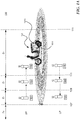
- FIG. 1A is a schematic diagram illustrating a system 100 in accordance with embodiments of the disclosed technology.
- the system 100 includes a vehicle 101 and a mobile device 103 carried by user 10 or a mobile device 105 carried by user 12.
- the vehicle 101 can include an electric vehicle, an electric scooter, a hybrid vehicle, or other suitable vehicles (e.g., vehicles having multiple states of power supply as shown in Figure 3A or 3B , or vehicles that can be powered by one or more batteries or other power storage devices, such as capacitors, cells, etc.).
- the mobile device 103 or 105 can include a smartphone, a tablet, a notebook, a wearable device, a portable controller, and/or other suitable devices.
- the vehicle 101 includes a processor 1013 and a distance measurement device 1011 (e.g., a wireless module such as a Bluetooth communication device/module or components with similar functions) configured to constantly monitor/search signals associated with the locations of the mobile device 103 or 105 (e.g., from the mobile device 103 or 105).
- the vehicle 101 can include one or more input/out (I/O) component configured to receive or present information associated with the vehicle 101.
- the I/O component can include a touch screen, a physical button, a virtual button on a display, a keypad, a lever (e.g., a brake lever), or other suitable components equipped on the vehicle.
- a method for controlling the vehicle 101 in accordance with the present technology can include, for example, (1) receiving a wireless signal from the mobile device 103 or 105; and (2) analyzing at least one characteristic of the wireless signal to determine a current location of the mobile device 103 or 105.
- the method can further include unlocking the vehicle 101 in response to a determination, based on the current location, that the mobile device 103 or 105 is within an inner boundary 111 adjacent to the vehicle 101, and that a first signal is received from a first input/output (I/O) component (e.g., a "GO" button, a "Start” button, and/or a brake lever) of the vehicle 101.
- the method can further include locking the vehicle 101 in response to a determination, based on the current location, that the mobile device 103 or 105 is external to an outer boundary 109 external to the inner boundary.
- I/O input/output
- the system can define four zones (Z 0 , Z 1 , Z 2 , and Z 3 ) by a signal boundary 107, the outer boundary (or far threshold) 109, and the inner boundary (or close threshold) 111.
- the signal boundary 107, the outer boundary 109, and the inner boundary 111 are concentric circles, and the center of these concentric circles is the vehicle 101.
- the signal boundary 107, the outer boundary 109, and the inner boundary 111 can have different shapes (e.g., embodiments to be discussed with reference to Figures 2B and 2C ).
- the inner boundary 111 and the outer boundary 109 can be determined or customized based on various factors such as, types of vehicles, types of communication components used by the vehicle 101 and the mobile device 103 or 105, a user configuration (e.g., a user can determine these boundaries based on the user's habits or the ways of operating the vehicle 101 via the dashboard of the vehicle 101 or the mobile device 103 or 105), etc.
- Zone Z 0 is defined as an area outside the signal boundary 107.
- the signal boundary 107 is determined based on whether the vehicle 101 can properly receive a signal from the mobile device 103 or 105 and establish a wireless connection thereby. When the mobile device 103 or 105 is within the signal boundary 107, the vehicle 101 can receive signals therefrom. When the mobile device 103 or 105 is not within the signal boundary 107, the vehicle 101 cannot properly receive a wireless signal from the mobile device 103 or 105.
- the signal boundary 107 can be an outer limit of the outer boundary 109.
- the wireless connection in addition to the distance requirement (e.g., within the signal boundary 107), can require an authentication process between the vehicle 101 and the mobile device 103 or 105 when establishing the wireless connection.
- Zone Z 1 is defined as an area between the signal boundary 107 and the outer boundary 109.
- Zone Z 2 is defined as an area between the outer boundary 109 and the inner boundary 111.
- Zone Z 3 is defined as an area within the inner boundary 101.
- the mobile device 103 or 105 can include an active wireless communication component (e.g., a Bluetooth component) configured to emitting signals so that the vehicle 101 can determine the location of the mobile device 103 or 105 by receiving the signals or analyzing the signals.
- an active wireless communication component e.g., a Bluetooth component
- the active wireless communication component can be controlled by an application (e.g., an app for controlling, operating, and/or communicating with the vehicle 101) installed in the mobile device 103 or 105.
- an application e.g., an app for controlling, operating, and/or communicating with the vehicle 101
- the application can instruct the active wireless communication component to measure the location of the mobile device 103 or 105.
- the active wireless communication component of the mobile device 103 or 105 can be an emitter that sends location signals (e.g., GPS signals) to the vehicle 101.
- the system 100 can lock or unlock the vehicle 101 during an unlocking process UP ( Figure 1B ) or a locking process LP ( Figure 1C ).
- an unlocking process UP Figure 1B
- a locking process LP Figure 1C
- the mobile device 103 carried by user 10 moves toward the vehicle 101 from Zone Z 0 to Zone Z 3 .
- Zone Z 0 the mobile device 103 is not connected to the vehicle 101.
- the system 100 can start to establish a communication between the mobile device 103 and the vehicle 101 (e.g., the vehicle 101 periodically receives wireless signals from the mobile device 103 and checks in with the mobile device 103 to see if it is still in Zone Z 1 ).
- the distance measurement device 1011 starts/keeps monitoring the locations of the mobile device 103 when it is in Zone Z 2 (e.g., the system 100 checks in with the mobile device 103 frequently to see if it is still in Zone Z 2 ).
- the processor 1013 of the vehicle 101 When the processor 1013 of the vehicle 101 detects that the mobile device 103 enters Zone Z 3 from Zone Z 2 through the monitoring from the distance measurement device 1011, the processor 1013 can activate a "Proximity-Auto-On" function of the vehicle 101. In some embodiments, in response to the entry of Zone Z 3 , the system 101 can generate an indication of that entry (e.g., a blink of light, a sound, etc.).
- an indication of that entry e.g., a blink of light, a sound, etc.
- the "Proximity-Auto-On” function can be performed by the processor 1013 (e.g., an engine or electric control unit, ECU) of the vehicle 101. In some embodiments, the "Proximity-Auto-On” function can be performed by a separate device (or a circuit, control logic, etc.) coupled to the processor 1013.
- the "Proximity-Auto-On” function is designed to automatically unlock the vehicle 101 (e.g., turn on its power provided by a battery) based on the locations/trajectories of the mobile device 103. After the "Proximity-Auto-On" function is activated, the distance measurement device 1011 keeps monitoring the location of the mobile device 103.
- the vehicle's battery power e.g., the main battery mentioned above
- the distance measurement device 1011 keeps monitoring the locations of the mobile device 103.
- the distance measurement device 1011 can transmit the location information of the mobile device 103 and then the processor 1013 can detect that the mobile device 103 enters Zone Z 3 .
- the distance measurement device 1011 can detect that the mobile device 103 enters Zone Z 3 , and notifies the processor 1013 of the vehicle 101.
- the processor 1013 of the vehicle 101 then "unlock" the vehicle by turning on the vehicle power (e.g., provided by a battery).
- a dashboard of the vehicle 101 is turned on such that user 10 can control the vehicle 101 via a user interface shown on the dashboard.
- the user 10 can then turn on an engine/motor of the vehicle 101 to operate the same.
- the processor 1013 determines that the mobile device 103 has entered Zone Z 3
- the processor 1013 can unlock the vehicle 101 if the processor 1013 receives one or more signals from input/output (I/O) components of the vehicle.
- the signals are generated in response to user operations such as pressing a "GO" button or a "START” button, holding a brake lever, a combination thereof, and/or other suitable operations.
- the user 10 can setup an order for receiving these signals. For example, the user 10 can decide using two signals (first and second signals) as “confirmation" for starting the engine/motor.
- the first signal can be responsive to pressing a button (e.g., a "GO” button or a "Start” button), and the second signal can be responsive to pulling or holding a brake lever.
- the first and second signal can both be responsive to pressing the button or pulling or holding the brake lever.
- the distance measurement device 1011 can provide information (e.g., signal strength or location information) of the mobile device 103 such that the processor 1013 can detect the entry and accordingly generate an audible or visual confirmation of the entry (e.g., a blink of light, a sound, etc.). In such embodiments, the distance measurement device 1011 keeps monitoring the locations of the when it is in Zone Z 1 . When the processor 1013 detects that the mobile device 103 enters Zone Z 2 , it can notify the system 100 to activate a "Proximity-Auto-On" function.
- the distance measurement device 1011 keeps monitoring the location of the mobile device 103 (in both Zone Z 2 and Z 3 ).
- the vehicle's battery power e.g., the main battery mentioned above
- engine/motor remain off.
- the distance measurement device 1011 keeps monitoring the locations of the mobile device 103.
- the processor 1013 detects that the mobile device 103 enters Zone Z 3 , it notifies the process of the vehicle 101.
- the processor 1013 of the vehicle 101 can then "unlock" the vehicle by turning on the vehicle power (e.g., provided by a battery or other power source(s) on the vehicle).
- a dashboard of the vehicle 101 is turned on such that the user 10 can control the vehicle 101 via a user interface shown on the dashboard.
- the user 10 can then turn on an engine or motor of the vehicle 101 to operate the same.
- FIG. 1B illustrates an unlocking process (UP) in accordance with embodiments of the disclosed technology.
- Zones Z 0- -Z 2 in Figure 1A can be combined and together named as Zone Z 4 .
- the “Proximity-Auto-On” function is activated.
- the vehicle's battery power e.g., the main battery mentioned above
- engine/motor remain off.
- a button (e.g., a physical button, a visual button, a "GO” button, etc.) of the vehicle can be activated or powered by a battery of the vehicle.
- the user 10 can then press the button to "power on” the vehicle (e.g., provide electricity power to multiple components of the vehicle, such as monitor, display, radio, etc.).
- the engine/motor remains off.
- the user 10 can then press the button again to start the engine/motor.
- the user 10 can first hold a brake lever of the vehicle (or press another button, in other embodiments) and then press the button to start the engine/motor.
- the user 10 can hold a brake lever of the vehicle 101 and press the button at the same time to start the engine/motor. In some embodiments, the user 10 can customize the way to start the engine/motor (e.g., pull the brake lever three times and then press the button) so as to enhance security of the vehicle and/or flexibility to control the vehicle 101.
- a timer is activated.
- the timer is configured to provide user 10 a period of time (e.g., 5 minutes) to start the engine/motor of the vehicle 101. If the user does not start the engine/motor for the period of time, the system 100 can then lock the vehicle 101 (e.g., turn off the battery power).
- the button can be disabled (e.g., power off) such that the user 10 can no longer press the button to start the engine/motor. This can save vehicle battery power and enhance vehicle security.
- the system 100 can periodically (e.g., every 35 seconds) check with the user 10 by sending notification to see if the user 10 still wants to keep the "Proximity-Auto-On" function activated. If so, the system 100 can unlock the vehicle 101 as described above. If not (e.g., no further operations from the user 10 via an app installed on the mobile device 103 or I/O components on the vehicle), the system 100 can deactivate the "Proximity-Auto-On" function. In some embodiments, the present system 100 allows the user 10 to set up the timing and location regarding when to activate the "Proximity-Auto-On" function.
- Table 1 below summaries the statuses and actions in different zones discussed in Figures 1A and 1B during the unlocking process in accordance with embodiments of the present disclosure.
- Table 1 Unlocking process Zone Z 0 (or Z 4 ) Zone Z 1 (or Z 4 ) Zone Z 2 (or Z 4 ) Zone Z 3 Mobile device Disconnected to vehicle Connected to vehicle Connected to vehicle Connected to vehicle Power status of Vehicle Locked (battery power off) Locked (battery power off) Locked (battery power off) Unlockable by user action (battery power on) "Proximity-Auto-On" Not activated Not activated Not activated Activated Timer Not activated Not activated Not activated Activated
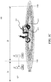
- FIG. 1C illustrates a locking process in accordance with embodiments of the present technology.
- Zones Z 2 and Z 3 in Figure 1A can be combined and together named as Zone Z 5
- Zones Z 0 and Z 1 in Figure 1A can be combined and together named as Zone Z 6 .
- the processor 1013 when a user 12 stops a vehicle and turns off the motor of the vehicle, the auto-locking process is activated.
- the processor 1013 then activates a "Proximity-Auto-Off" function and instructs the distance measurement device 1011 to monitor the location of the mobile device 105.
- the processor 1013 when the processor 1013 detects that the mobile device 105 carried by the user 12 moves away from Zone Z 5 to Zone Z 6 (i.e., across the outer boundary 109 and away from the vehicle 101), the processor 1013 can perform the "Proximity-Auto-Off" function to turn off the battery power of the vehicle 101.
- the user 12 can still do so by sending instructions to the vehicle 101 by the mobile device 105 (e.g., pressing a "lock” button shown in a user interface of the app installed on the mobile device 105).
- the vehicle 101 remains unlocked.
- the user 12 cannot fully control the vehicle 101, e.g., directly turning on the engine/motor, by the mobile device 105 or I/O components on the vehicle 101.
- the vehicle 101 is unlocked, the user 12 is able to fully control the vehicle 101 by the mobile device 105, including turning on the engine/motor (e.g., by pressing a "GO" button, as discussed above with reference to Figure 1B ).
- the vehicle 101 can be locked by the "Proximity-Auto-Off" function when the distance measurement device 1011 or the processor 1013 detects that the mobile device 105 carried by the user 12 moves away from Zone Z 5 to Zone Z 6 (i.e., across the outer boundary 109).
- the processor 1013 when the processor 1013 detects that the mobile device 105 carried by the user 12 moves away from Zone Z 5 to Zone Z 6 , the processor 1013 can perform the "Proximity-Auto-Off" function to turn off the battery power of the vehicle 101 and lock vehicle 101.
- the processor 1013 when the processor 1013 detects that the mobile device 105 moves from Zone Z 2 to Zone Z 1 , if the battery power is still on, the processor 1013 of the vehicle 101 will turn off the battery power and locks the vehicle 101. The system 100 will also deactivate the "Proximity-Auto-Off" function.
- the system 100 can provide a time buffer (e.g., 1-5 seconds; counted by a timer of the processor 1013 or the vehicle 101) before it turns off the battery power of the vehicle 101.
- the time buffer can be set by a user (e.g., user 10 or 12).
- the timer can be used to track how long the mobile device 105 has been stayed in Zone Z 2 or Zone Z 3 so as to determine whether the user moves away from the vehicle 101 (in that case, the vehicle 101 can be locked for security purposes) or the user simply moves around in Zone Z 2 or Zone Z 3 without intention to leave the vehicle 101 (in that case, the vehicle 101 remain unlocked).
- Table 2 below summaries the statuses and actions in different zones discussed in Figures 1A and 1C during the locking process in accordance with embodiments of the present disclosure.
- Table 2 Locking Process Zone Z 0 (or Z 6 ) Zone Z 1 (or Z 6 ) Zone Z 2 (or Z 5 ) Zone Z 3 (or Z 5 ) Mobile device Disconnected to vehicle Connected to vehicle Connected to vehicle Power status of Vehicle Locked (battery power off) Locked (battery power off) Unlocked (battery power off; lockable by user action) Vehicle stops; Engine/motor off; unlocked (battery power on) "Proximity-Auto-Off" Not activated Not activated Activated Activated Timer Not activated Not activated Activated Activated Activated
- the system 100 enables a user to configure various "responses" from the vehicle 101 in various zones. For example, there can be more zones (e.g., more than 4 zones) than described in the embodiments above. For example, in some embodiments, a user can have five zones (e.g., Zone A 0 -A 4 , in the direction toward the vehicle 101). For example, in Zone A 0 , the system 100 can start to establish a connection with a mobile device. In Zone A 1 , the system 100 can periodically monitoring the location of the mobile device. In Zone A 2 , the system 100 can keep monitoring the location of the mobile device (e.g., more frequently than it does in Zone A1).
- Zone A 0 the system 100 can start to establish a connection with a mobile device.
- Zone A 1 the system 100 can periodically monitoring the location of the mobile device.
- Zone A 2 the system 100 can keep monitoring the location of the mobile device (e.g., more frequently than it does in Zone A1).
- the system 100 can instruct the vehicle 101 to send a sound notification (e.g., play a sound, a song, or a melody) toward the mobile device.
- a sound notification e.g., play a sound, a song, or a melody
- the system 100 can activate the "Proximity-Auto-On" function and turn on the power of the vehicle 101 as described above.
- the sound notification can vary based on dates.
- the sound notification can be a birthday song on the user's birthday.
- the sound notification can be a holiday greeting song on a holiday (e.g., New Year, Christmas, etc.).
- when system 100 activates the "Proximity-Auto-On" function it can also play a set of sounds or a song from a speaker of the vehicle 101.
- the system 100 can keep playing a song when the "Proximity-Auto-On" function is activated (e.g., a 5-min-long song).
- the user 10 or 12 can be notified and accordingly take an action (e.g., press a "GO” button to turn on the power of the vehicle 101, or press a "GO” button and holding a brake lever at the same time to start an engine/motor of the vehicle 101).
- an action e.g., press a "GO” button to turn on the power of the vehicle 101, or press a "GO” button and holding a brake lever at the same time to start an engine/motor of the vehicle 101.
- these "response" from the vehicle 101 can include a movement of the vehicle 101.
- the vehicle 101 e.g., a self-balanced, four-wheeled vehicle, or a three-wheeled vehicle with a tilt mechanism locked during power off stage
- the vehicle 101 can be parked in a narrow parking space in Zone A 4 .
- the mobile device e.g., the mobile device 103 or 105
- Zone A 4 e.g., where the vehicle 101 is located
- the vehicle 101 can move a bit toward the mobile device from the narrow parking space, such that the user 10 or 12 can easily access the vehicle 101.
- the number of zones can be adjusted based on user preferences, actual needs, and/or the number of events/responses during locking/unlocking processes.
- the responses can include (i) providing power to an indicative light of the vehicle 101, (ii) playing a sound from a speaker of the vehicle 101, and/or (iii) providing power to an engine/motor of the vehicle to cause a movement of the vehicle 101.
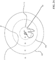
- FIG. 2A is a schematic diagram (top view) illustrating multiple trajectories T 1 , T 2 of a movable object (e.g., mobile device 103 or 105 discussed above) associated with a vehicle 201 in accordance with embodiments of the disclosed technology.
- the present system can lock (e.g., turn off battery power) or unlock (e.g., turn on battery power) the vehicle 201 based on predetermined trajectories of the movable object.
- trajectory T 1 indicates that the moving object moved toward the vehicle 201 from Zone Z 0 to Zone Z 2 , without further entering Zone Z 3 .
- the system will activate the "Proximity-Auto-On” function when the movable object enters Zone Z 2 or continuously monitor whether the movable object enters Zone Z 3 or not so as to activate the "Proximity-Auto-On” function (based on a setting regarding in which zone to activate the "Proximity-Auto-On” function).
- the system determines that there were many occasions that the moveable object travelled along trajectory T 1 but a user did not eventually turn on an engine/motor of the vehicle 201, the system can accordingly adjust its Zone Z 2 by moving the outer boundary 109 toward the vehicle 201 (such that a movement along trajectory T 1 will not trigger the "Proximity-Auto-On” function).
- trajectory T 2 indicates that the moving object moved toward the vehicle 201 from Zone Z 0 to Zone Z 3 , returned to Zone Z 2 , and re-entered Zone Z 3 several times.
- the system will activate the "Proximity-Auto-On" function when the movable object enters Zone Z 2 , and then turns on the battery power of the vehicle 201 once the moveable objects enters Zone Z 3 .
- the system can accordingly adjust its Zone Z 3 by moving the inner boundary 111 further toward the vehicle 201 (such that the system will only turn on the battery power of the vehicle 201 when the moveable object is very close to the vehicle 201.
- the size/shape of the inner boundary 111 can be dynamically adjusted.
- Figure 2B is a schematic diagram (top view) illustrating multiple non-concentric zones (Zones Z 0-3 ) associated with the vehicle 201 in accordance with embodiments of the disclosed technology.
- the zones can be determined by a user and do not need to be concentric.
- these non-concentric zones can be configured to accommodate various factors, such as quality difference of signals from various directions (e.g., the vehicle 201 can receive signals with better quality in direction A than direction B).
- the zones can be determined based on user behavior. For example, a user often approaches the vehicle 201 in direction C.
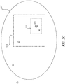
- Zone 2C is a schematic diagram (top view) illustrating multiple zones (Zones Z 0-3 ) with various shapes associated with the vehicle 201 in accordance with embodiments of the disclosed technology.
- Zone Z 3 can be a rectangular (e.g., a shape of a parking space)
- Zone Z 2 can be a square (e.g., a shape of a building)
- Zone Z 1 can be an ellipse (e.g., a shape of a company campus or a residential area).
- the shapes and sizes of these zones can be adjusted based on user preferences, user behavior, environmental factors, etc.
- a user may adjust the size of the inner boundary and outer boundary via an app installed on the mobile device, for example, based on the user's personal preference.
- the shapes of zones can be determined by a geo-fence or the like.
- FIG. 3A is a schematic diagram illustrating various states of a vehicle during an auto-unlocking process in accordance with embodiments of the disclosed technology.
- the vehicle is in a "locked” state, where its battery power and engine/motor are both turned off.
- the vehicle is moved to a "Proximity-Auto-On” state, at block 303, the vehicle's battery power and engine/motor remain turned off, but a "Proximity-Auto-On" function is activated to monitor the location of a mobile device associated with the vehicle, such that the system can determine whether to turn on the battery power of the vehicle (e.g., "unlock" the vehicle).
- the vehicle at the "Proximity-Auto-On” state (block 303), there is only limited function accessible to a user of the vehicle. For example, only some of the I/O components are enabled/turned on, so that the user can only (1) unlock the vehicle by pressing a start button (e.g., a "GO” button) or (2) open a trunk of the vehicle by pressing another function key or button.
- a start button e.g., a "GO” button
- the vehicle is moved to an "unlocked” state, where its battery power is turned on but its engine/motor is still turned off.
- the vehicle can be "unlocked” (e.g., from block 303 to block 305) by the "Proximity-Auto-On” function, in response to a detection of a movement or location change of the mobile device associated with the vehicle and/or by receiving an unlock signal sent from authenticated mobile device or key fob.
- the vehicle state moves from “unlocked” at block 305 to "ready-to-operate” at block 307.
- Figure 3B is a schematic diagram illustrating various states of a vehicle during an auto-locking process in accordance with embodiments of the disclosed technology.
- a user stops the vehicle, but its engine/motor remains on. After the user turns off the engine/motor, the state of the vehicle moves to "unlocked” at block 305.
- the system activates a "Proximity-Auto-Off” function to monitor the location of a mobile device associated with the vehicle, so as to determine when to turn off battery power of the vehicle (e.g., lock the vehicle).
- the vehicle can be "locked” (e.g., from block 305 to block 301) by the "Proximity-Auto-Off” function, in response to a detection of a movement or location change of the mobile device associated with the vehicle, showing that the user moves away from the vehicle.
- the vehicle is "locked” at block 301, its battery power and engine/motor are both turned off.
- the system can skip the unlocked state (block 305), and directly set the vehicle state from the "engine on” state (corresponding to block 309) to the "locked” state (block 301).
- FIG 4 is a schematic diagram illustrating a system 400 in accordance with embodiments of the disclosed technology which can be referred to the system 100 in Figure. 1A .
- the system 400 includes and an electric vehicle 41 and a mobile device 43.
- the mobile device 43 can include a smartphone, a tablet, a smart watch, a notebook, other type of computing device, etc.
- the mobile device 43 can also be a wireless key fob with actively wireless signal transmission ability or the like.
- the electric vehicle 41 can be an electric scooter or other vehicles with security mechanisms.
- the electric vehicle 41 can communicate with the mobile device 43 via a direct wireless connection or a wireless network (e.g., Bluetooth, infrared, Wi-Fi, 3G/4G/5G, etc.).
- the mobile device 43 and/or the electric vehicle 41 can further communicate with a server 45 (e.g., update its location).
- the wireless communication network between the mobile device 43 and the server 45 can be different from the wireless communication network or the direct wireless connection between the electric vehicle 41 and the server 45.
- the mobile device 43 is configured with an application (e.g., an app) that instructs the processor of the mobile device to communicate with a processor 409 of the electric vehicle 41 through a wireless communication link.
- the app uses a Bluetooth wireless communication protocol to communicate with a paired receiver in the electric vehicle 41.
- the Bluetooth protocol establishes a communication link whenever the paired deices are in range.
- the receiver in the electric vehicle 41 can therefore use a received signal strength of the Bluetooth signal as an indicator of how close the mobile device is to the vehicle (e.g., the RSSI).
- a user can activate the electric vehicle 41 (pressing a "GO" command on a dashboard) without requiring any additional key entries from the user.
- the received signal strength of the Bluetooth communication signals indicates when the user has walked away from the electric vehicle 41 and can turn the vehicle off if the signal strength drops below a predetermined minimum strength.
- the processor 409 in the electric vehicle 41 can send periodic beacons that are coded to match a code of the mobile device 43.
- a processor 401 of the mobile device 43 Upon receipt of the beacon, a processor 401 of the mobile device 43 sends a signal back to the electric vehicle 41 with an indication of its position (e.g., GPS coordinates).
- the signals between the electric vehicle 41 and the mobile device 43 are encrypted or encoded so that only the correct paired mobile device 43 is able to activate or turn off the electric vehicle 41.
- the processor 401 of the mobile device 43 uses an unlocking mechanism of the mobile device 43 (e.g., code, thumbprint, facial recognition, etc.) to generate a signal to the electric vehicle 41 that allows the electric vehicle 41 to be unlocked).
- the processor 401 of the mobile device 43 may prompt the user for their thumb print and upon successful presentation of the thumb print, send a message to the electric vehicle 41 confirming that the electric vehicle 41 can be started.
- the mobile device 43 is programmed by the app to send periodic beacon signals that are encoded for the electric vehicle 41. Upon receipt of a beacon signal, the mobile device 43 and the vehicle begin transmitting signals via a wireless link indicating the position of the mobile device 43 so that the processor 409 in the electric vehicle 41 can implement the lock/unlock procedures described.
- the electric vehicle 41 includes the processor 409, a memory 411, a battery 413, a motor 415, an input device 417, a dashboard display 419, and a communication component 421.
- the processor 409 is configured to interact with the memory 411 and other components (e.g., components 413-421) in the electric vehicle 41.
- the memory 411 is coupled to the processor 409 and configured to store instructions for controlling other components or other information in the electric vehicle 41.
- the battery 413 can be the main battery mentioned above and is configured to power the motor 415 such that the motor 415 can move the electric vehicle 41.
- the dashboard display 419 is configured to visually present information to a user.
- the communication component 421 is configured to communicate with other systems (e.g., the mobile device 43 or the server 45).
- the mobile device 43 includes the processor 401, a location management component 403, a storage component 405, and a communication component 407.
- the processor 401 is configured to control other components of the mobile device 43 and to execute instructions to perform desired operations.
- the location management component 403 is configured to track locations of the mobile device 43 (e.g., including trajectories showing locations in the past). In some embodiments, the locations of the mobile device 43 can be measured by a GPS sensor (not shown). In some embodiments, the location information can include data measured by a gyro sensor or an accelerometer. The location information can be stored in the storage component 405 or uploaded to the server 45. The location management component 403 is configured to provide the tracked location information of the mobile device 43.
- the location measurement component 417 is configured to measure the location of the mobile device 43 based on a wireless signal strength (e.g., Bluetooth signal strength) or other signal characteristics.
- the measured locations of the mobile device 43 can be analyzed to determine the current location of the mobile device 43, such that to determine whether to activate a "Proximity-Auto-On" function discussed above.
- the measured locations are also used to determine whether to lock or unlock the electric vehicle 41 by turning off or turning on power supplied by the battery 413.
- the mobile device 43 can be implemented as a controller or a system-on-chip (SOC) system that can perform the functions described above.
- the location measurement component 417 can use two or more information sources to verify the location of the mobile device 43.
- the location measurement component 417 can use Bluetooth signal strength as well as signals or information regarding movements of the mobile device (e.g., signals or information generated by an accelerator or a gyroscope in the mobile device 43).
- the electric vehicle 41 can include (i) a wireless module (e.g., the communication component 421) configured to establish a wireless connection with the mobile device 43 to receive wireless signals from the mobile device 43; (ii) a processor (e.g., the processor 401) configured to analyze at least one characteristic of the wireless connection to determine a current location of the mobile device 43; and (iii) a first input/output (I/O) component (e.g., the input device 417 or the dashboard display 419) configured to generate a first signal in response to a user action.
- a wireless module e.g., the communication component 421 configured to establish a wireless connection with the mobile device 43 to receive wireless signals from the mobile device 43
- a processor e.g., the processor 401 configured to analyze at least one characteristic of the wireless connection to determine a current location of the mobile device 43
- a first input/output (I/O) component e.g., the input device 417 or the dashboard display 419 configured to generate a first signal in response to
- the processor can be further configured to unlock the electric vehicle 41 in response to a determination, based on the current location, that the mobile device 43 is within an inner boundary (e.g., the inner boundary 111) adjacent to the electric vehicle 41, and that the first signal is received.
- the processor 401 can be further configured to lock the electric vehicle 41 in response to a determination, based on the current location, that the mobile device 43 is external to an outer boundary (e.g., the outer boundary 109) external to the inner boundary.
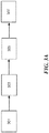
- FIGS 5-7 are flowcharts illustrating methods 500, 600 and 700 in accordance with embodiments of the disclosed technology.
- the method 500 can be used to control (e.g., unlock or lock) a vehicle by turning on or turning off battery power of the vehicle.
- the method 500 can be implemented by a vehicle and a mobile device.
- the mobile device can be implemented as a controller, a stand-alone chip set or circuitry, or other types of suitable devices.
- the method 500 starts at block 501 by receiving a wireless signal (e.g., a Bluetooth signal) from a mobile device.
- the method 500 continues by analyzing at least one characteristic (e.g., signal strength) of the wireless signal so as to determine a current location of the mobile device (e.g., a distance between the vehicle and the mobile device).
- a wireless signal e.g., a Bluetooth signal
- the method 500 then proceeds to unlock the vehicle in response to a determination, based on the current location, that the mobile device is within an inner boundary adjacent to the vehicle (or a determination that the mobile device moves across the inner boundary), and that a first signal is received from a first input/output (I/O) component of the vehicle.
- the method 500 can, in response to a determination that the current location is in a first predetermined zone (e.g., Zone Z 3 discussed above with reference to Figures 1A-2C ) adjacent to the vehicle, enable an engine/motor of the vehicle to be turned on by receiving instructions through a component (e.g., a display or a button) of the vehicle powered by a battery of the vehicle.
- a component e.g., a display or a button
- the method 500 continues by, locking the vehicle in response to a determination, based on the current location, that the mobile device is external to an outer boundary external to the inner boundary (or a determination that the mobile device moves across the outer boundary).
- the method 500 can include, in response to a determination that the current location is in a second predetermined zone (e.g., Zone Z 2 discussed above with reference to Figures 1A-2C ) next to the first predetermined zone, enabling the engine/motor of the vehicle to be turned off.
- the engine/motor of the vehicle can be turned off automatically in response to the determination that the current location is in the second predetermined zone (if the engine/motor has not been turned off by a user).
- the method when determining that the current location of the mobile device is in the second predetermined zone, after the engine/motor has been turned off, the method can enable the engine/motor to be further turned on by receiving instructions through the component (e.g., a display or a button) of the vehicle powered by the battery.
- the component e.g., a display or a button
- the unlocking process at block 505 and the locking process at block 507 can be implemented separately based on actual use (e.g., only the unlocking process at block 505 is implemented without the implementation of block 507, or vice versa).
- the method 600 is directed to lock a vehicle (e.g., turn its battery power or other power source off) based on a location or moving trajectory of a mobile device associated with the vehicle.
- the method 600 includes, at block 601, (1) receiving a wireless signal from a mobile device; (2) analyzing at least one characteristic of the wireless signal so as to determine a current location of the mobile device (block 603); and (3) if the current location is external to an outer boundary, locking the vehicle, for example, by turning off the power supply from the battery and/or turning off a button of the vehicle powered by a battery of the vehicle (block 605).
- turning off the button of the vehicle disables an engine/motor of the vehicle to be turned on by receiving instructions through the button.
- the method 700 is directed to unlock a vehicle (e.g., turn its battery power on) based on a location or moving trajectory of a mobile device associated with the vehicle.
- the method 700 includes, at block 701, (1) receiving a wireless signal from a mobile device; (2) analyzing at least one characteristic of the wireless signal so as to determine a current location of the mobile device (block 703); and (3) at least partially based on the current location, determining whether to unlock the vehicle by, for example, turning on a button of the vehicle powered by a battery of the vehicle (block 705).
- turning on the button of the vehicle enables an engine/motor of the vehicle to be turned on by receiving instructions through the button.
Landscapes
- Engineering & Computer Science (AREA)
- Mechanical Engineering (AREA)
- Computer Networks & Wireless Communication (AREA)
- Signal Processing (AREA)
- Transportation (AREA)
- Chemical & Material Sciences (AREA)
- Combustion & Propulsion (AREA)
- Physics & Mathematics (AREA)
- General Physics & Mathematics (AREA)
- Lock And Its Accessories (AREA)
- Automobile Manufacture Line, Endless Track Vehicle, Trailer (AREA)
Applications Claiming Priority (1)
| Application Number | Priority Date | Filing Date | Title |
|---|---|---|---|
| US201862732984P | 2018-09-18 | 2018-09-18 |
Publications (2)
| Publication Number | Publication Date |
|---|---|
| EP3626548A1 true EP3626548A1 (de) | 2020-03-25 |
| EP3626548B1 EP3626548B1 (de) | 2020-12-02 |
Family
ID=67988894
Family Applications (1)
| Application Number | Title | Priority Date | Filing Date |
|---|---|---|---|
| EP19197675.2A Active EP3626548B1 (de) | 2018-09-18 | 2019-09-17 | Verfahren zum ver- und/oder entriegeln eines elektrofahrzeugs und zugehörige vorrichtung |
Country Status (8)
| Country | Link |
|---|---|
| US (1) | US11377071B2 (de) |
| EP (1) | EP3626548B1 (de) |
| JP (1) | JP7061098B2 (de) |
| KR (1) | KR102433475B1 (de) |
| CN (1) | CN110905312B (de) |
| ES (1) | ES2848201T3 (de) |
| PH (1) | PH12019000348B1 (de) |
| TW (2) | TWI777769B (de) |
Cited By (4)
| Publication number | Priority date | Publication date | Assignee | Title |
|---|---|---|---|---|
| EP4016002A1 (de) * | 2020-12-17 | 2022-06-22 | Nxp B.V. | Infrastruktursteuerung für eine infrastruktur |
| DE102021120220A1 (de) | 2021-08-04 | 2023-02-09 | Bayerische Motoren Werke Aktiengesellschaft | Verfahren zum Steuern eines Fahrzeugzugangs, computerlesbares Medium, System, und Fahrzeug |
| DE102022118778A1 (de) | 2022-07-27 | 2024-02-01 | Dr. Ing. H.C. F. Porsche Aktiengesellschaft | Fahrzeug, Vorrichtung und Verfahren für eine Annäherungserkennung für das Fahrzeug |
| DE102022118777A1 (de) | 2022-07-27 | 2024-02-01 | Dr. Ing. H.C. F. Porsche Aktiengesellschaft | Fahrzeug, Vorrichtung und Verfahren zum sensorbasierten Konfigurieren einer Annäherungserkennung für das Fahrzeug |
Families Citing this family (33)
| Publication number | Priority date | Publication date | Assignee | Title |
|---|---|---|---|---|
| US20210170989A1 (en) * | 2019-12-09 | 2021-06-10 | James Andrew Cameron | Anti Theft Device for Open Air Compartment Vehicles |
| DE102020109360A1 (de) | 2020-04-03 | 2021-10-07 | Ford Global Technologies, Llc | System und Verfahren zur Automatisierung von Fahrzeugfunktionen |
| DE102020109379A1 (de) * | 2020-04-03 | 2021-10-07 | Ford Global Technologies, Llc | Verfahren und System zum automatisierten Ausführen von Fahrzeugfunktionen |
| CN111629325A (zh) * | 2020-04-30 | 2020-09-04 | 福建鸿兴福食品有限公司 | 电池控制方法、控制装置及计算机可读存储介质 |
| GB2597498A (en) * | 2020-07-24 | 2022-02-02 | Continental Automotive Gmbh | System and method for controlling vehicle |
| CN111824289A (zh) * | 2020-07-29 | 2020-10-27 | 雅迪科技集团有限公司 | 一种基于蓝牙的电动车启动方法及系统 |
| US11325563B2 (en) * | 2020-08-06 | 2022-05-10 | GM Global Technology Operations LLC | Approach-based vehicle system actuation |
| CN112158163A (zh) * | 2020-08-20 | 2021-01-01 | 赛格威科技有限公司 | 车辆上下电控制方法、装置、系统及全地形车 |
| KR102219891B1 (ko) * | 2020-09-29 | 2021-02-24 | 주식회사 튠잇 | 키 제어 방법 및 키 제어 장치 |
| CN114368356A (zh) * | 2020-10-15 | 2022-04-19 | 华为技术有限公司 | 一种车辆控制方法、车载装置和移动终端 |
| KR102493306B1 (ko) * | 2020-12-16 | 2023-01-31 | 여태환 | 생체 인식 기반으로 이륜차에 대한 운전자 특정 시동 제어 및 운전 정보 생성을 수행하기 위한 장치 및 방법 |
| CN113060094B (zh) * | 2021-04-29 | 2022-07-26 | 北京车和家信息技术有限公司 | 一种车辆的控制方法、装置和车载设备 |
| JP7655096B2 (ja) * | 2021-06-03 | 2025-04-02 | 株式会社デンソー | 車両用防犯装置及び車両用防犯システム |
| CN115695623A (zh) * | 2021-07-28 | 2023-02-03 | 华为技术有限公司 | 电子设备控制方法及相关设备 |
| DE102022003321A1 (de) | 2021-09-15 | 2023-03-16 | Mercedes-Benz Group AG | System und Verfahren zum Fernparken eines Fahrzeugs |
| US12296744B2 (en) | 2021-10-11 | 2025-05-13 | Ford Global Technologies, Llc | Baseplate mounting system with locking mechanism |
| CN114005203A (zh) * | 2021-11-19 | 2022-02-01 | 中山市澳多电子科技有限公司 | 一种智能家庭锁及其控制方法 |
| US12409809B2 (en) | 2022-02-25 | 2025-09-09 | Honda Motor Co., Ltd. | Remote control of vehicle features based on tactile gestures on electronic device |
| CN116767134B (zh) * | 2022-03-10 | 2025-12-23 | 上海博泰悦臻网络技术服务有限公司 | 锁车安全提醒方法、系统和可读存储介质 |
| US12351129B2 (en) * | 2022-04-25 | 2025-07-08 | Toyota Research Institute, Inc. | Systems and methods to utilize user trajectory analysis for automatic vehicle controls |
| US20230403536A1 (en) * | 2022-06-10 | 2023-12-14 | Centurylink Intellectual Property Llc | Wi-Fi-Disruption Based Motion Detection and Automation System and Methods |
| CN115393983A (zh) * | 2022-08-10 | 2022-11-25 | 上海派智能源股份有限公司 | 智能锁具的控制方法、控制系统、设备及介质 |
| US20240049830A1 (en) * | 2022-08-12 | 2024-02-15 | Reby Inc. | Helmet detection in truck with RFID |
| US12012070B2 (en) * | 2022-09-21 | 2024-06-18 | Ford Global Technologies, Llc | Consignment delivery methods and systems |
| US12059956B2 (en) * | 2022-10-28 | 2024-08-13 | Rivian Ip Holdings, Llc | Systems and methods for providing transient vehicle features |
| JP2024073202A (ja) * | 2022-11-17 | 2024-05-29 | 株式会社Subaru | 車両用電力マネジメントシステム |
| TWI865995B (zh) * | 2022-12-16 | 2024-12-11 | 英屬開曼群島商鴻騰精密科技股份有限公司 | 電動自行車之狀態控制方法、控制系統與相關設備 |
| CN118212712A (zh) | 2022-12-16 | 2024-06-18 | 富士康(昆山)电脑接插件有限公司 | 电动自行车的状态控制方法、控制系统和电子设备 |
| TWI874920B (zh) * | 2023-02-24 | 2025-03-01 | 光陽工業股份有限公司 | 車輛控制方法及系統 |
| FR3148560A1 (fr) * | 2023-05-11 | 2024-11-15 | Psa Automobiles Sa | Systeme comprenant un bouchon antivol destine a un vehicule electrique ou hybride et procede mettant en œuvre ledit systeme |
| KR102895061B1 (ko) * | 2023-06-14 | 2025-12-02 | 충북대학교 산학협력단 | 택시호출 및 차량공유 서비스 사용자간 상호인식 및 인증시스템 및 방법 |
| WO2025022460A1 (en) * | 2023-07-26 | 2025-01-30 | Ola Electric Mobility Private Limited | A method and a system for controlling a vehicle based on user's intent |
| DE102024103450A1 (de) * | 2024-02-08 | 2025-08-14 | Bayerische Motoren Werke Aktiengesellschaft | Verfahren zum Steuern eines Verriegelungssystems, Steuerungssystem sowie Kraftrad |
Citations (8)
| Publication number | Priority date | Publication date | Assignee | Title |
|---|---|---|---|---|
| DE19826904A1 (de) * | 1998-06-17 | 1999-12-23 | Mannesmann Vdo Ag | Funkschlüssel |
| DE10064141A1 (de) * | 2000-12-21 | 2002-07-25 | Siemens Ag | Verfahren zum Nachweis einer Berechtigung zum Ver- oder Entriegeln oder der Benutzung eines Objekts sowie Sicherheitsvorrichtung |
| US6700475B1 (en) * | 1999-03-19 | 2004-03-02 | Daimlerchrysler | Electronic closure system, in particular a vehicle closure system |
| EP1669264A1 (de) * | 2003-09-29 | 2006-06-14 | HONDA MOTOR CO., Ltd. | Fernbedienungsschlüssel für fahrzeug |
| US20070200669A1 (en) * | 2006-02-24 | 2007-08-30 | Denso International America, Inc. | Apparatus for automatically initiating sequence of vehicle functions |
| US20070241862A1 (en) * | 2006-04-12 | 2007-10-18 | Dimig Steven J | Transponder authorization system and method |
| US20100075656A1 (en) * | 2008-09-24 | 2010-03-25 | Embarq Holdings Company, Llc | System and method for key free access to a vehicle |
| WO2017182556A1 (en) * | 2016-04-21 | 2017-10-26 | Hella Kgaa Hueck & Co. | A system and a method for immobilization of vehicles |
Family Cites Families (40)
| Publication number | Priority date | Publication date | Assignee | Title |
|---|---|---|---|---|
| JPS6278379A (ja) * | 1985-09-30 | 1987-04-10 | 日産自動車株式会社 | 車両用施解錠制御装置 |
| JP3192715B2 (ja) | 1991-12-04 | 2001-07-30 | 富士通テン株式会社 | 車両用ワイヤレスドアロック制御装置 |
| US6359348B1 (en) * | 1999-11-15 | 2002-03-19 | Lear Corporation | Semi-passive keyless entry method and device |
| JP4022859B2 (ja) | 2002-03-19 | 2007-12-19 | オムロン株式会社 | ドアロック制御装置 |
| JP3930386B2 (ja) | 2002-06-21 | 2007-06-13 | 株式会社東海理化電機製作所 | 電子キーシステム |
| US7466219B2 (en) | 2004-10-19 | 2008-12-16 | Sanyo Electric Co., Ltd. | Communication device and distance calculation system |
| US8325026B2 (en) * | 2005-04-29 | 2012-12-04 | Heistproof, Llc | Remote ignition, theft deterrence, and records keeping system for a vehicle |
| JP4929760B2 (ja) | 2006-03-02 | 2012-05-09 | 日本電気株式会社 | 携帯電話端末装置および電子鍵装置 |
| JP2008189104A (ja) | 2007-02-05 | 2008-08-21 | Calsonic Kansei Corp | ヘッドアップディスプレイ認証装置 |
| JP5451168B2 (ja) * | 2009-04-28 | 2014-03-26 | アルプス電気株式会社 | 車両のキーレスエントリー装置 |
| JP5273110B2 (ja) * | 2010-09-08 | 2013-08-28 | 株式会社デンソー | 発進制御装置 |
| JP5794047B2 (ja) | 2011-09-05 | 2015-10-14 | スズキ株式会社 | 自動二輪車の制御装置 |
| FR2986202A1 (fr) | 2012-01-26 | 2013-08-02 | Johnson Contr Automotive Elect | Moyen d'authentification portable et systeme de securite de vehicule pour un vehicule automobile |
| US8868254B2 (en) | 2012-06-08 | 2014-10-21 | Apple Inc. | Accessory control with geo-fencing |
| JP6211288B2 (ja) | 2013-04-05 | 2017-10-11 | アイシン精機株式会社 | 車両用オートドア操作装置、および車両に設けられる装飾部品 |
| GB2517128B (en) | 2013-05-31 | 2015-12-09 | Jaguar Land Rover Ltd | Vehicle communication system |
| US20160063786A1 (en) | 2014-08-26 | 2016-03-03 | Hyundai America Technical Center, Inc. | Smartphone enabled passive entry go system |
| JP6331959B2 (ja) * | 2014-10-21 | 2018-05-30 | 株式会社デンソー | 車載装置 |
| US9862353B2 (en) * | 2014-12-17 | 2018-01-09 | Denso International America, Inc. | Vehicle system and method for keyless authentication and control of an ignition system |
| US9799220B2 (en) * | 2015-02-04 | 2017-10-24 | Trw Automotive U.S. Llc | Keyless entry system linked to vehicle-to-vehicle communications system |
| JP6104311B2 (ja) * | 2015-05-13 | 2017-03-29 | 三菱電機株式会社 | 車両情報表示装置 |
| CN108351993B (zh) * | 2015-08-04 | 2022-09-27 | 睿能创意公司 | 用于电动载具共享的装置、方法和物品 |
| TW201709713A (zh) * | 2015-08-31 | 2017-03-01 | Chunghwa Telecom Co Ltd | 智慧型手機自動上解鎖車門的系統與方法 |
| KR101768134B1 (ko) | 2015-09-21 | 2017-08-14 | 현대자동차주식회사 | 자동차용 시스템 전원 제어 장치 및 그 제어방법 |
| TWI561718B (en) | 2015-12-03 | 2016-12-11 | Brainchild Electronic Co Ltd | Door-lock system and door-lock control method |
| JP2017128884A (ja) | 2016-01-19 | 2017-07-27 | 株式会社東海理化電機製作所 | 車両用ドアロック装置 |
| JP6614999B2 (ja) | 2016-02-23 | 2019-12-04 | 株式会社東海理化電機製作所 | 電子キーシステム |
| JP2017160761A (ja) | 2016-03-11 | 2017-09-14 | オムロンオートモーティブエレクトロニクス株式会社 | 車両制御装置 |
| KR101718072B1 (ko) | 2016-03-30 | 2017-03-20 | 현대자동차주식회사 | 차량 및 차량의 제어방법 |
| TWI759295B (zh) * | 2016-04-12 | 2022-04-01 | 德商羅伯特博斯奇股份有限公司 | 用於二輪車的上鎖裝置及其操作的方法 |
| DE102017121765A1 (de) * | 2016-09-20 | 2018-03-22 | Huf Hülsbeck & Fürst Gmbh & Co. Kg | Verfahren zur Aktivierung mindestens einer Funktion eines Fahrzeugs |
| US10031523B2 (en) | 2016-11-07 | 2018-07-24 | Nio Usa, Inc. | Method and system for behavioral sharing in autonomous vehicles |
| DE102016221924A1 (de) * | 2016-11-09 | 2018-05-09 | Audi Ag | Verfahren zum Betreiben einer Zentralverriegelungsvorrichtung, Zentralverriegelungsvorrichtung und Kraftfahrzeug |
| CN114022981A (zh) | 2016-12-14 | 2022-02-08 | 余仁植 | 一种车辆解锁方法、锁定解锁装置、车辆及车辆系统 |
| GB2558590A (en) * | 2017-01-09 | 2018-07-18 | Jaguar Land Rover Ltd | Vehicle entry system |
| JP2018115463A (ja) | 2017-01-18 | 2018-07-26 | 株式会社東海理化電機製作所 | 電子キーシステム、電子制御装置および受信機 |
| WO2018191894A1 (zh) * | 2017-04-19 | 2018-10-25 | 深圳市汇顶科技股份有限公司 | 一种车辆解锁方法及车辆解锁系统 |
| TWM561877U (zh) | 2017-12-08 | 2018-06-11 | Cycling & Health Tech Ind R&D Center | 共享單車之使用管理系統 |
| TWM562879U (zh) * | 2018-03-29 | 2018-07-01 | 陳澤興 | 無線門鎖裝置及具有該無線門鎖裝置之生物辨識門鎖控制系統 |
| US11055936B2 (en) * | 2019-05-02 | 2021-07-06 | Voxx International Corporation | Multi-sensor passive keyless functionality |
-
2019
- 2019-08-15 US US16/542,250 patent/US11377071B2/en active Active
- 2019-08-23 TW TW110134207A patent/TWI777769B/zh active
- 2019-08-23 TW TW108130315A patent/TWI757629B/zh active
- 2019-08-26 JP JP2019153941A patent/JP7061098B2/ja active Active
- 2019-08-27 KR KR1020190105094A patent/KR102433475B1/ko active Active
- 2019-09-12 PH PH1/2019/000348A patent/PH12019000348B1/en unknown
- 2019-09-17 ES ES19197675T patent/ES2848201T3/es active Active
- 2019-09-17 EP EP19197675.2A patent/EP3626548B1/de active Active
- 2019-09-18 CN CN201910882621.XA patent/CN110905312B/zh active Active
Patent Citations (8)
| Publication number | Priority date | Publication date | Assignee | Title |
|---|---|---|---|---|
| DE19826904A1 (de) * | 1998-06-17 | 1999-12-23 | Mannesmann Vdo Ag | Funkschlüssel |
| US6700475B1 (en) * | 1999-03-19 | 2004-03-02 | Daimlerchrysler | Electronic closure system, in particular a vehicle closure system |
| DE10064141A1 (de) * | 2000-12-21 | 2002-07-25 | Siemens Ag | Verfahren zum Nachweis einer Berechtigung zum Ver- oder Entriegeln oder der Benutzung eines Objekts sowie Sicherheitsvorrichtung |
| EP1669264A1 (de) * | 2003-09-29 | 2006-06-14 | HONDA MOTOR CO., Ltd. | Fernbedienungsschlüssel für fahrzeug |
| US20070200669A1 (en) * | 2006-02-24 | 2007-08-30 | Denso International America, Inc. | Apparatus for automatically initiating sequence of vehicle functions |
| US20070241862A1 (en) * | 2006-04-12 | 2007-10-18 | Dimig Steven J | Transponder authorization system and method |
| US20100075656A1 (en) * | 2008-09-24 | 2010-03-25 | Embarq Holdings Company, Llc | System and method for key free access to a vehicle |
| WO2017182556A1 (en) * | 2016-04-21 | 2017-10-26 | Hella Kgaa Hueck & Co. | A system and a method for immobilization of vehicles |
Cited By (6)
| Publication number | Priority date | Publication date | Assignee | Title |
|---|---|---|---|---|
| EP4016002A1 (de) * | 2020-12-17 | 2022-06-22 | Nxp B.V. | Infrastruktursteuerung für eine infrastruktur |
| DE102021120220A1 (de) | 2021-08-04 | 2023-02-09 | Bayerische Motoren Werke Aktiengesellschaft | Verfahren zum Steuern eines Fahrzeugzugangs, computerlesbares Medium, System, und Fahrzeug |
| DE102022118778A1 (de) | 2022-07-27 | 2024-02-01 | Dr. Ing. H.C. F. Porsche Aktiengesellschaft | Fahrzeug, Vorrichtung und Verfahren für eine Annäherungserkennung für das Fahrzeug |
| DE102022118777A1 (de) | 2022-07-27 | 2024-02-01 | Dr. Ing. H.C. F. Porsche Aktiengesellschaft | Fahrzeug, Vorrichtung und Verfahren zum sensorbasierten Konfigurieren einer Annäherungserkennung für das Fahrzeug |
| DE102022118777B4 (de) | 2022-07-27 | 2025-05-08 | Dr. Ing. H.C. F. Porsche Aktiengesellschaft | Fahrzeug, Vorrichtung und Verfahren zum sensorbasierten Konfigurieren einer Annäherungserkennung für das Fahrzeug |
| US12377814B2 (en) | 2022-07-27 | 2025-08-05 | Dr. Ing. H.C. F. Porsche Aktiengesellschaft | Vehicle, apparatus, and method for sensor-based configuration of an approach detection for the vehicle |
Also Published As
| Publication number | Publication date |
|---|---|
| JP7061098B2 (ja) | 2022-04-27 |
| EP3626548B1 (de) | 2020-12-02 |
| TWI777769B (zh) | 2022-09-11 |
| JP2020079542A (ja) | 2020-05-28 |
| CN110905312A (zh) | 2020-03-24 |
| US20200086829A1 (en) | 2020-03-19 |
| CN110905312B (zh) | 2021-04-13 |
| US11377071B2 (en) | 2022-07-05 |
| ES2848201T3 (es) | 2021-08-05 |
| TWI757629B (zh) | 2022-03-11 |
| TW202200890A (zh) | 2022-01-01 |
| TW202035846A (zh) | 2020-10-01 |
| KR20200033170A (ko) | 2020-03-27 |
| PH12019000348A1 (en) | 2020-03-23 |
| PH12019000348B1 (en) | 2023-09-06 |
| KR102433475B1 (ko) | 2022-08-18 |
Similar Documents
| Publication | Publication Date | Title |
|---|---|---|
| EP3626548B1 (de) | Verfahren zum ver- und/oder entriegeln eines elektrofahrzeugs und zugehörige vorrichtung | |
| US11818630B2 (en) | System and method for locating a portable device in different zones relative to a vehicle and with device zone indicators | |
| JP7303109B2 (ja) | 電動車の制御方法及び電動車 | |
| US10917750B2 (en) | System and method for locating a portable device in different zones relative to a vehicle and enabling vehicle control functions | |
| US20250336249A1 (en) | Scheme for setting/using electronic device as keyless device of vehicle and adjusting devices in the vehicle | |
| US10562540B2 (en) | Method and apparatus for vehicle valet control devices | |
| KR102220597B1 (ko) | 스쿠터 | |
| KR20120116563A (ko) | 스마트키 시스템, 그의 차량 제어 장치 및 방법 | |
| TWI802691B (zh) | 用於便攜式鎖之手持式發送器、鎖定系統及解鎖可電致動的便攜式鎖的方法 | |
| TW202006230A (zh) | 便攜式鎖 | |
| JP2021165141A (ja) | オープンキャビンビークル及び携帯端末 | |
| CN113696848A (zh) | 一种摩托车无钥匙启动的控制方法及系统 | |
| KR102425634B1 (ko) | 스마트폰 방치 방지 기능을 구비한 차량용 오디오장치 및 그의 제어방법 | |
| CN109255876B (zh) | 一种智能车锁开关装置、智能车锁、车辆及控制方法 | |
| CN121757084A (zh) | 一种具有个性化配置功能的智能汽车钥匙 |
Legal Events
| Date | Code | Title | Description |
|---|---|---|---|
| STAA | Information on the status of an ep patent application or granted ep patent |
Free format text: STATUS: EXAMINATION IS IN PROGRESS |
|
| PUAI | Public reference made under article 153(3) epc to a published international application that has entered the european phase |
Free format text: ORIGINAL CODE: 0009012 |
|
| 17P | Request for examination filed |
Effective date: 20190917 |
|
| AK | Designated contracting states |
Kind code of ref document: A1 Designated state(s): AL AT BE BG CH CY CZ DE DK EE ES FI FR GB GR HR HU IE IS IT LI LT LU LV MC MK MT NL NO PL PT RO RS SE SI SK SM TR |
|
| AX | Request for extension of the european patent |
Extension state: BA ME |
|
| GRAP | Despatch of communication of intention to grant a patent |
Free format text: ORIGINAL CODE: EPIDOSNIGR1 |
|
| STAA | Information on the status of an ep patent application or granted ep patent |
Free format text: STATUS: GRANT OF PATENT IS INTENDED |
|
| RIC1 | Information provided on ipc code assigned before grant |
Ipc: B60R 25/24 20130101AFI20200626BHEP Ipc: G07C 9/00 20200101ALI20200626BHEP |
|
| INTG | Intention to grant announced |
Effective date: 20200716 |
|
| RIN1 | Information on inventor provided before grant (corrected) |
Inventor name: WALL, KENNETH EDWARD Inventor name: LAI, MING-HSIANG Inventor name: CHEN, CHING Inventor name: WU, JIA-YANG Inventor name: HSU, CHUN-SHENG |
|
| GRAS | Grant fee paid |
Free format text: ORIGINAL CODE: EPIDOSNIGR3 |
|
| GRAA | (expected) grant |
Free format text: ORIGINAL CODE: 0009210 |
|
| STAA | Information on the status of an ep patent application or granted ep patent |
Free format text: STATUS: THE PATENT HAS BEEN GRANTED |
|
| AK | Designated contracting states |
Kind code of ref document: B1 Designated state(s): AL AT BE BG CH CY CZ DE DK EE ES FI FR GB GR HR HU IE IS IT LI LT LU LV MC MK MT NL NO PL PT RO RS SE SI SK SM TR |
|
| REG | Reference to a national code |
Ref country code: GB Ref legal event code: FG4D |
|
| REG | Reference to a national code |
Ref country code: CH Ref legal event code: EP Ref country code: AT Ref legal event code: REF Ref document number: 1340582 Country of ref document: AT Kind code of ref document: T Effective date: 20201215 |
|
| REG | Reference to a national code |
Ref country code: DE Ref legal event code: R096 Ref document number: 602019001580 Country of ref document: DE |
|
| REG | Reference to a national code |
Ref country code: IE Ref legal event code: FG4D |
|
| REG | Reference to a national code |
Ref country code: NL Ref legal event code: FP |
|
| PG25 | Lapsed in a contracting state [announced via postgrant information from national office to epo] |
Ref country code: FI Free format text: LAPSE BECAUSE OF FAILURE TO SUBMIT A TRANSLATION OF THE DESCRIPTION OR TO PAY THE FEE WITHIN THE PRESCRIBED TIME-LIMIT Effective date: 20201202 Ref country code: RS Free format text: LAPSE BECAUSE OF FAILURE TO SUBMIT A TRANSLATION OF THE DESCRIPTION OR TO PAY THE FEE WITHIN THE PRESCRIBED TIME-LIMIT Effective date: 20201202 Ref country code: GR Free format text: LAPSE BECAUSE OF FAILURE TO SUBMIT A TRANSLATION OF THE DESCRIPTION OR TO PAY THE FEE WITHIN THE PRESCRIBED TIME-LIMIT Effective date: 20210303 Ref country code: NO Free format text: LAPSE BECAUSE OF FAILURE TO SUBMIT A TRANSLATION OF THE DESCRIPTION OR TO PAY THE FEE WITHIN THE PRESCRIBED TIME-LIMIT Effective date: 20210302 |
|
| REG | Reference to a national code |
Ref country code: AT Ref legal event code: MK05 Ref document number: 1340582 Country of ref document: AT Kind code of ref document: T Effective date: 20201202 |
|
| PG25 | Lapsed in a contracting state [announced via postgrant information from national office to epo] |
Ref country code: BG Free format text: LAPSE BECAUSE OF FAILURE TO SUBMIT A TRANSLATION OF THE DESCRIPTION OR TO PAY THE FEE WITHIN THE PRESCRIBED TIME-LIMIT Effective date: 20210302 Ref country code: LV Free format text: LAPSE BECAUSE OF FAILURE TO SUBMIT A TRANSLATION OF THE DESCRIPTION OR TO PAY THE FEE WITHIN THE PRESCRIBED TIME-LIMIT Effective date: 20201202 Ref country code: PL Free format text: LAPSE BECAUSE OF FAILURE TO SUBMIT A TRANSLATION OF THE DESCRIPTION OR TO PAY THE FEE WITHIN THE PRESCRIBED TIME-LIMIT Effective date: 20201202 Ref country code: SE Free format text: LAPSE BECAUSE OF FAILURE TO SUBMIT A TRANSLATION OF THE DESCRIPTION OR TO PAY THE FEE WITHIN THE PRESCRIBED TIME-LIMIT Effective date: 20201202 |
|
| PG25 | Lapsed in a contracting state [announced via postgrant information from national office to epo] |
Ref country code: HR Free format text: LAPSE BECAUSE OF FAILURE TO SUBMIT A TRANSLATION OF THE DESCRIPTION OR TO PAY THE FEE WITHIN THE PRESCRIBED TIME-LIMIT Effective date: 20201202 |
|
| REG | Reference to a national code |
Ref country code: LT Ref legal event code: MG9D |
|
| PG25 | Lapsed in a contracting state [announced via postgrant information from national office to epo] |
Ref country code: LT Free format text: LAPSE BECAUSE OF FAILURE TO SUBMIT A TRANSLATION OF THE DESCRIPTION OR TO PAY THE FEE WITHIN THE PRESCRIBED TIME-LIMIT Effective date: 20201202 Ref country code: RO Free format text: LAPSE BECAUSE OF FAILURE TO SUBMIT A TRANSLATION OF THE DESCRIPTION OR TO PAY THE FEE WITHIN THE PRESCRIBED TIME-LIMIT Effective date: 20201202 Ref country code: PT Free format text: LAPSE BECAUSE OF FAILURE TO SUBMIT A TRANSLATION OF THE DESCRIPTION OR TO PAY THE FEE WITHIN THE PRESCRIBED TIME-LIMIT Effective date: 20210405 Ref country code: EE Free format text: LAPSE BECAUSE OF FAILURE TO SUBMIT A TRANSLATION OF THE DESCRIPTION OR TO PAY THE FEE WITHIN THE PRESCRIBED TIME-LIMIT Effective date: 20201202 Ref country code: SK Free format text: LAPSE BECAUSE OF FAILURE TO SUBMIT A TRANSLATION OF THE DESCRIPTION OR TO PAY THE FEE WITHIN THE PRESCRIBED TIME-LIMIT Effective date: 20201202 Ref country code: SM Free format text: LAPSE BECAUSE OF FAILURE TO SUBMIT A TRANSLATION OF THE DESCRIPTION OR TO PAY THE FEE WITHIN THE PRESCRIBED TIME-LIMIT Effective date: 20201202 Ref country code: CZ Free format text: LAPSE BECAUSE OF FAILURE TO SUBMIT A TRANSLATION OF THE DESCRIPTION OR TO PAY THE FEE WITHIN THE PRESCRIBED TIME-LIMIT Effective date: 20201202 |
|
| REG | Reference to a national code |
Ref country code: ES Ref legal event code: FG2A Ref document number: 2848201 Country of ref document: ES Kind code of ref document: T3 Effective date: 20210805 |
|
| PG25 | Lapsed in a contracting state [announced via postgrant information from national office to epo] |
Ref country code: AT Free format text: LAPSE BECAUSE OF FAILURE TO SUBMIT A TRANSLATION OF THE DESCRIPTION OR TO PAY THE FEE WITHIN THE PRESCRIBED TIME-LIMIT Effective date: 20201202 |
|
| REG | Reference to a national code |
Ref country code: DE Ref legal event code: R097 Ref document number: 602019001580 Country of ref document: DE |
|
| PG25 | Lapsed in a contracting state [announced via postgrant information from national office to epo] |
Ref country code: IS Free format text: LAPSE BECAUSE OF FAILURE TO SUBMIT A TRANSLATION OF THE DESCRIPTION OR TO PAY THE FEE WITHIN THE PRESCRIBED TIME-LIMIT Effective date: 20210402 |
|
| PLBE | No opposition filed within time limit |
Free format text: ORIGINAL CODE: 0009261 |
|
| STAA | Information on the status of an ep patent application or granted ep patent |
Free format text: STATUS: NO OPPOSITION FILED WITHIN TIME LIMIT |
|
| PG25 | Lapsed in a contracting state [announced via postgrant information from national office to epo] |
Ref country code: AL Free format text: LAPSE BECAUSE OF FAILURE TO SUBMIT A TRANSLATION OF THE DESCRIPTION OR TO PAY THE FEE WITHIN THE PRESCRIBED TIME-LIMIT Effective date: 20201202 |
|
| 26N | No opposition filed |
Effective date: 20210903 |
|
| PG25 | Lapsed in a contracting state [announced via postgrant information from national office to epo] |
Ref country code: DK Free format text: LAPSE BECAUSE OF FAILURE TO SUBMIT A TRANSLATION OF THE DESCRIPTION OR TO PAY THE FEE WITHIN THE PRESCRIBED TIME-LIMIT Effective date: 20201202 Ref country code: SI Free format text: LAPSE BECAUSE OF FAILURE TO SUBMIT A TRANSLATION OF THE DESCRIPTION OR TO PAY THE FEE WITHIN THE PRESCRIBED TIME-LIMIT Effective date: 20201202 |
|
| REG | Reference to a national code |
Ref country code: BE Ref legal event code: MM Effective date: 20210930 |
|
| PG25 | Lapsed in a contracting state [announced via postgrant information from national office to epo] |
Ref country code: IS Free format text: LAPSE BECAUSE OF FAILURE TO SUBMIT A TRANSLATION OF THE DESCRIPTION OR TO PAY THE FEE WITHIN THE PRESCRIBED TIME-LIMIT Effective date: 20210402 Ref country code: MC Free format text: LAPSE BECAUSE OF FAILURE TO SUBMIT A TRANSLATION OF THE DESCRIPTION OR TO PAY THE FEE WITHIN THE PRESCRIBED TIME-LIMIT Effective date: 20201202 |
|
| PG25 | Lapsed in a contracting state [announced via postgrant information from national office to epo] |
Ref country code: LU Free format text: LAPSE BECAUSE OF NON-PAYMENT OF DUE FEES Effective date: 20210917 Ref country code: IE Free format text: LAPSE BECAUSE OF NON-PAYMENT OF DUE FEES Effective date: 20210917 Ref country code: BE Free format text: LAPSE BECAUSE OF NON-PAYMENT OF DUE FEES Effective date: 20210930 |
|
| PGFP | Annual fee paid to national office [announced via postgrant information from national office to epo] |
Ref country code: NL Payment date: 20220926 Year of fee payment: 4 |
|
| REG | Reference to a national code |
Ref country code: CH Ref legal event code: PL |
|
| PG25 | Lapsed in a contracting state [announced via postgrant information from national office to epo] |
Ref country code: CY Free format text: LAPSE BECAUSE OF FAILURE TO SUBMIT A TRANSLATION OF THE DESCRIPTION OR TO PAY THE FEE WITHIN THE PRESCRIBED TIME-LIMIT Effective date: 20201202 |
|
| PG25 | Lapsed in a contracting state [announced via postgrant information from national office to epo] |
Ref country code: LI Free format text: LAPSE BECAUSE OF NON-PAYMENT OF DUE FEES Effective date: 20220930 Ref country code: HU Free format text: LAPSE BECAUSE OF FAILURE TO SUBMIT A TRANSLATION OF THE DESCRIPTION OR TO PAY THE FEE WITHIN THE PRESCRIBED TIME-LIMIT; INVALID AB INITIO Effective date: 20190917 Ref country code: CH Free format text: LAPSE BECAUSE OF NON-PAYMENT OF DUE FEES Effective date: 20220930 |
|
| PG25 | Lapsed in a contracting state [announced via postgrant information from national office to epo] |
Ref country code: MK Free format text: LAPSE BECAUSE OF FAILURE TO SUBMIT A TRANSLATION OF THE DESCRIPTION OR TO PAY THE FEE WITHIN THE PRESCRIBED TIME-LIMIT Effective date: 20201202 |
|
| REG | Reference to a national code |
Ref country code: NL Ref legal event code: MM Effective date: 20231001 |
|
| GBPC | Gb: european patent ceased through non-payment of renewal fee |
Effective date: 20230917 |
|
| PG25 | Lapsed in a contracting state [announced via postgrant information from national office to epo] |
Ref country code: NL Free format text: LAPSE BECAUSE OF NON-PAYMENT OF DUE FEES Effective date: 20231001 |
|
| PG25 | Lapsed in a contracting state [announced via postgrant information from national office to epo] |
Ref country code: TR Free format text: LAPSE BECAUSE OF FAILURE TO SUBMIT A TRANSLATION OF THE DESCRIPTION OR TO PAY THE FEE WITHIN THE PRESCRIBED TIME-LIMIT Effective date: 20201202 Ref country code: NL Free format text: LAPSE BECAUSE OF NON-PAYMENT OF DUE FEES Effective date: 20231001 |
|
| PG25 | Lapsed in a contracting state [announced via postgrant information from national office to epo] |
Ref country code: GB Free format text: LAPSE BECAUSE OF NON-PAYMENT OF DUE FEES Effective date: 20230917 |
|
| PG25 | Lapsed in a contracting state [announced via postgrant information from national office to epo] |
Ref country code: GB Free format text: LAPSE BECAUSE OF NON-PAYMENT OF DUE FEES Effective date: 20230917 |
|
| PG25 | Lapsed in a contracting state [announced via postgrant information from national office to epo] |
Ref country code: MT Free format text: LAPSE BECAUSE OF FAILURE TO SUBMIT A TRANSLATION OF THE DESCRIPTION OR TO PAY THE FEE WITHIN THE PRESCRIBED TIME-LIMIT Effective date: 20201202 |
|
| PGFP | Annual fee paid to national office [announced via postgrant information from national office to epo] |
Ref country code: DE Payment date: 20250929 Year of fee payment: 7 |
|
| PGFP | Annual fee paid to national office [announced via postgrant information from national office to epo] |
Ref country code: IT Payment date: 20250919 Year of fee payment: 7 |
|
| PGFP | Annual fee paid to national office [announced via postgrant information from national office to epo] |
Ref country code: FR Payment date: 20250925 Year of fee payment: 7 |
|
| PGFP | Annual fee paid to national office [announced via postgrant information from national office to epo] |
Ref country code: ES Payment date: 20251001 Year of fee payment: 7 |