EP3626646A1 - Boîte empilable - Google Patents
Boîte empilable Download PDFInfo
- Publication number
- EP3626646A1 EP3626646A1 EP19190409.3A EP19190409A EP3626646A1 EP 3626646 A1 EP3626646 A1 EP 3626646A1 EP 19190409 A EP19190409 A EP 19190409A EP 3626646 A1 EP3626646 A1 EP 3626646A1
- Authority
- EP
- European Patent Office
- Prior art keywords
- side wall
- box
- wall sections
- contact surfaces
- stacking direction
- Prior art date
- Legal status (The legal status is an assumption and is not a legal conclusion. Google has not performed a legal analysis and makes no representation as to the accuracy of the status listed.)
- Granted
Links
Images


Classifications
-
- B—PERFORMING OPERATIONS; TRANSPORTING
- B65—CONVEYING; PACKING; STORING; HANDLING THIN OR FILAMENTARY MATERIAL
- B65D—CONTAINERS FOR STORAGE OR TRANSPORT OF ARTICLES OR MATERIALS, e.g. BAGS, BARRELS, BOTTLES, BOXES, CANS, CARTONS, CRATES, DRUMS, JARS, TANKS, HOPPERS, FORWARDING CONTAINERS; ACCESSORIES, CLOSURES, OR FITTINGS THEREFOR; PACKAGING ELEMENTS; PACKAGES
- B65D21/00—Nestable, stackable or joinable containers; Containers of variable capacity
- B65D21/02—Containers specially shaped, or provided with fittings or attachments, to facilitate nesting, stacking, or joining together
- B65D21/0209—Containers specially shaped, or provided with fittings or attachments, to facilitate nesting, stacking, or joining together stackable or joined together one-upon-the-other in the upright or upside-down position
- B65D21/0212—Containers presenting local stacking elements protruding from the upper or lower edge of a side wall, e.g. handles, lugs, ribs, grooves
-
- B—PERFORMING OPERATIONS; TRANSPORTING
- B65—CONVEYING; PACKING; STORING; HANDLING THIN OR FILAMENTARY MATERIAL
- B65D—CONTAINERS FOR STORAGE OR TRANSPORT OF ARTICLES OR MATERIALS, e.g. BAGS, BARRELS, BOTTLES, BOXES, CANS, CARTONS, CRATES, DRUMS, JARS, TANKS, HOPPERS, FORWARDING CONTAINERS; ACCESSORIES, CLOSURES, OR FITTINGS THEREFOR; PACKAGING ELEMENTS; PACKAGES
- B65D1/00—Rigid or semi-rigid containers having bodies formed in one piece, e.g. by casting metallic material, by moulding plastics, by blowing vitreous material, by throwing ceramic material, by moulding pulped fibrous material or by deep-drawing operations performed on sheet material
- B65D1/22—Boxes or like containers with side walls of substantial depth for enclosing contents
-
- B—PERFORMING OPERATIONS; TRANSPORTING
- B65—CONVEYING; PACKING; STORING; HANDLING THIN OR FILAMENTARY MATERIAL
- B65D—CONTAINERS FOR STORAGE OR TRANSPORT OF ARTICLES OR MATERIALS, e.g. BAGS, BARRELS, BOTTLES, BOXES, CANS, CARTONS, CRATES, DRUMS, JARS, TANKS, HOPPERS, FORWARDING CONTAINERS; ACCESSORIES, CLOSURES, OR FITTINGS THEREFOR; PACKAGING ELEMENTS; PACKAGES
- B65D81/00—Containers, packaging elements, or packages, for contents presenting particular transport or storage problems, or adapted to be used for non-packaging purposes after removal of contents
- B65D81/24—Adaptations for preventing deterioration or decay of contents; Applications to the container or packaging material of food preservatives, fungicides, pesticides or animal repellants
- B65D81/26—Adaptations for preventing deterioration or decay of contents; Applications to the container or packaging material of food preservatives, fungicides, pesticides or animal repellants with provision for draining away, or absorbing, or removing by ventilation, fluids, e.g. exuded by contents; Applications of corrosion inhibitors or desiccators
- B65D81/261—Adaptations for preventing deterioration or decay of contents; Applications to the container or packaging material of food preservatives, fungicides, pesticides or animal repellants with provision for draining away, or absorbing, or removing by ventilation, fluids, e.g. exuded by contents; Applications of corrosion inhibitors or desiccators for draining or collecting liquids without absorbing them
Definitions
- the present invention relates to a stackable crate for receiving and transporting objects and for stacking on top of one another in a stacking direction with at least one other crate of the same type, the crate comprising a base and a protruding from the base and at least partially, in particular completely, around the base has circumferential side wall, the bottom and the side wall together delimiting a receiving space of the box for receiving the objects and the side wall in a plan view of the box has a, in particular rectangular, basic shape with, in particular four, corner areas and side wall sections running between the corner areas, wherein the side wall sections running between the corner areas are each delimited by an upper side of the side wall section inclined at least in regions obliquely to the stacking direction and an underside of the side wall section arranged opposite thereto.
- Boxes of this type are, for example, in the EP 1 287 780 B1 shown.
- the boxes stacked one on top of the other are each set down in their corner areas.
- the top sides of the side wall sections between the corner areas are inclined to the stacking direction. This has the advantage that water and / or other liquids or moisture run off the inclined upper sides of the side wall sections following the slope, and the upper sides of the side wall sections dry faster. This is particularly advantageous if the boxes are used in a washing and / or rinsing process.
- a disadvantage of the construction according to the EP 1 287 780 B1 is that the maximum possible load of such boxes is limited.
- the object of the invention is therefore to improve generic stackable boxes so that on the one hand they have side walls that dry as quickly as possible, but on the other hand they also enable high payloads.
- the invention proposes that on the side wall sections on the upper sides of the side wall sections in each case adjacent to at least one region of the respective upper side which is inclined obliquely to the stacking direction, preferably between two of these obliquely inclined regions of the respective upper side, above this or these at an angle inclined area (s) protruding contact surfaces and / or on the undersides of the side wall sections over at least one area adjacent thereto, preferably two adjacent areas, protruding contact areas on the respective underside.
- the areas of the upper side of the side wall sections remaining between the contact surfaces are inclined at an angle to the stacking direction, so that water and other liquids flow away rapidly from the upper sides of the side wall sections and thus promote rapid drying of the side wall sections.
- the contact surfaces projecting beyond the respective adjacent areas can be attached to both the upper sides and the lower sides of the side wall sections.
- the undersides of the side wall sections of the respective upper box lie exclusively in the area of the contact surfaces on the upper sides of the side wall sections of the respective lower box. This advantageously results from the fact that the regions of the respective upper sides of the respective upper sides which are inclined to the stacking direction Sidewall sections of the lower box are spaced from the regions of the undersides of the sidewall sections of the respective upper box arranged above. This creates an air gap between the respective upper sides of the side wall sections of the respective lower box and the lower sides of the side wall sections of the respective upper box, which in turn promotes the rapid drying of the side walls. It is also advantageously provided that the boxes stacked one on top of the other do not touch in the corner areas. This is achieved in that the contact areas also protrude beyond the corner areas of the side wall of the box.
- Stackable boxes according to the invention could also be referred to as transport and / or storage boxes or generally as containers or transport containers. Even if they are designed for mechanical gripping by means of at least one gripping device, they can of course also be conveniently gripped and transported by hand.
- mechanical gripping is to be understood to mean that a crate is contacted physically by means of a gripping device in such a way that it is raised with the gripping devices in the machine-gripped, that is to say in other words machine-contacted or machine-handled, state , transported or moved in any other way.
- Stackable boxes according to the invention can be used in very different areas. In principle, it is conceivable to use such stackable boxes for storing, washing and transporting dishes, glasses and the like. Such machine-accessible stackable boxes are particularly preferably used in the industrial environment, in order to store, transport, wash and similar objects which are to be processed, manufactured or manufactured in industry.
- the minimum load capacity of stackable boxes according to the invention is advantageously at least 10 kg, particularly preferably 25 kg per box.
- Stackable boxes according to the invention can also be dimensioned very differently. These are preferably boxes with a rectangular or square basic shape.
- the length of the box is advantageously in the range from 10 cm to 120 cm, preferably from 25 cm to 65 cm, and its width in the range from 10 cm to 100 cm, preferably 25 cm to 45 cm.
- the height of the box is in the range from 3 cm to 25 cm, preferably from 4 cm to 15 cm.
- Crates according to the invention can consist of different materials or material compositions. It can be metal boxes but also plastic boxes. Even wooden or composite boxes are conceivable. In any case, it is preferably provided that the stackable box is formed in one piece. This then also means that the side wall and the base are then connected to one another in one piece and consist of the same material.
- the boxes according to the invention can be made of a suitable plastic, e.g. Trade polypropylene (PP), polyamide (PA), polyoxymethylene (POM) or polybutylene terephthalate (PBT). Boxes according to the invention can e.g. are manufactured by injection molding.
- Boxes according to the invention have a bottom which delimits the receiving space of the box, into which the objects can be placed, together with the peripheral side wall.
- the box with the floor is usually placed on the ground so that the objects in the recording room lie on the floor.
- the floor therefore usually forms the support surface for the objects in the receiving space of the box.
- the receiving space is delimited by the peripheral side wall of the box.
- the side wall when closed, can completely surround the floor. But it can also be made of several components that are interrupted. Even then it can still be a peripheral side wall. Both the side wall and the bottom can be designed as self-contained surfaces.
- the circumferential side wall is composed of corner areas and, preferably straight, side wall sections running between the corner areas.
- the side wall can have a rectangular basic shape in a plan view of the box.
- the term rectangular is not only to be understood in the strict mathematical sense. It also includes configurations in which the side wall sections in principle converge at a right angle in the corner area, but the corner area itself nevertheless has roundings and the like, etc.
- boxes according to the invention are designed such that they can be stacked on top of one another together with other boxes of the same type in a stacking direction.
- the stacking direction is generally predetermined by the shape of the box or its base and its side wall. E.g. the floor can protrude beyond the side wall, so that this protruding area of the bottom of a box can be placed in the upper area of the receiving space of the box below it, i.e. in the area which is surrounded by the side wall, so that the bottom of the upper box faces the Sides is held positively from the side wall of the lower box.
- This also automatically results in the corresponding stacking direction in which the boxes must be stacked on top of one another.
- the features according to the invention must be implemented with respect to at least one stacking direction so that it is a box according to the invention.
- the bottom forms an upper, in particular flat, boundary surface with which it delimits the receiving space.
- the stacking direction is then advantageously normal to this upper boundary surface of the floor.
- the stacking direction then forms a surface normal to this upper boundary surface of the floor.
- the upper boundary surface of the floor limits the receiving space of the box downwards, while the side wall limits the receiving space in this position of the box to the sides, that is to say in horizontal directions.
- the boundary surface is spanned from the top of the floor. This also applies if the base is lattice-shaped or the like.
- the upper, in particular flat, boundary surface is the surface on which, in the operating position, the objects stored in the box in the receiving space lie.
- the stacking direction is used here as a reference direction at several points.
- the above-mentioned, in particular flat, boundary surface of the floor could also be used as a geometric reference, it then having to be assumed that the stacking direction forms a surface normal to this upper boundary surface of the floor, i.e. orthogonally on all sides on the upper boundary surface of the floor stands.
- Crates according to the invention can be open at the top, that is to say on the side of the side wall facing away from the floor. In other words, such boxes have an upwardly open receiving space.
- stackable boxes according to the invention can of course also be closed with a lid on the side of the receiving space opposite the floor by attaching a corresponding lid on this side of a side wall.
- FIGS 1 to 19 The first exemplary embodiment of the invention, which is shown in FIGS 1 to 19 is shown. The following description of the further exemplary embodiments then focuses on the differences from the first exemplary embodiment.
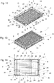
- the inventive box 1 of the first embodiment is in the 1 to 11 stacked in the stacking direction 2 on another box 1 according to the invention of the same type.
- the Fig. 12-19 show this box 1 of the first embodiment individually or partial areas thereof.
- the crate 1 has a base 3 and a side wall 4 which projects beyond the base 3 parallel to the stacking direction 2 and in this exemplary embodiment is completely formed around the base 3.
- the bottom 3 and the side wall 4 together delimit the receiving space 5 of the box 1, which is provided for receiving the objects in the box.
- the receiving space 5 is bounded downwards by an upper, here flat boundary surface 17 of the bottom 3.
- the stacking direction 2 forms a surface normal to this upper boundary surface 17 of the bottom 3. In other words, the stacking direction 2 is normal to the upper boundary surface 17 of the bottom 3.
- the stacking direction 2 is also predetermined in this exemplary embodiment in that the bottom is used to stack the boxes 1 on top of one another 3 of the respective upper box 1 must be inserted into the upper area of the receiving space 5 of the lower box 1 surrounded by the side wall 4. Like this for example in Fig. 2 is clearly visible, this results in a form fit in the direction orthogonal to the stacking direction 2. This has the consequence that the boxes 1 must be stacked on top of each other in the stacking direction 2 and for stacking the respective upper box or Boxes 1 against the stacking direction 2 must be lifted from the lower box or boxes 1.
- both the bottom 3 and the side wall 4 can be designed as self-contained surfaces. This is not the case in this embodiment.
- both the bottom 3 and the side walls 4 each have openings or openings.
- the base 3 is formed by a lattice-shaped structure.
- the side wall 4 has a multiplicity of window-like openings. All of this is of course only shown by way of example and can also be carried out in other ways known per se. Above all, as far as necessary for the intended application, reinforcing ribs and the like can be formed both on the bottom 3 and on the side wall 4.
- the boxes 1 shown here have a rectangular basic shape with four corner regions 16 which are rounded in this exemplary embodiment. In each case, side wall sections 21 run between corner regions 16.
- side wall 4 which runs completely around floor 3, is thus formed from four corner regions 16 and the preferably straight side wall sections 21 running between them.
- boxes 1 according to the invention are also conceivable and possible with a basic shape that is not rectangular, but differently designed.
- the preferred side wall sections 21 realized here are each straight or linear. They meet an adjacent side wall section 21 at an orthogonal angle in the corner regions 16. Of course, this does not have to be the case either.
- the number of corner regions 16 and the number and shape of the side wall sections 21 can of course also be designed differently.
- the boxes 1 are designed with spaced apart adapters for mechanical gripping of the box 1 by means of at least one gripping device 6.
- the adapters are each formed in the side wall 4 as channels 8 which are elongated in a longitudinal direction 7 extending parallel to the stacking direction 2, the channels 8 in each case an inlet opening 9 and an outlet opening 10 and in between one in the respective longitudinal direction delimited by a channel boundary wall 11 of the box 1 7 have longitudinally extending inner channel cavity 12 for guiding the gripping device 6 through the inlet opening 9 and the inner channel cavity 12 and the outlet opening 10.
- the channel boundary wall 11 is advantageously, as is also realized here, in each case in the form of a partial region of the side wall 4.
- the channel boundary wall 11 delimits the inner channel cavity 12 in a circumferentially closed manner.
- Circumference closed means that the channel boundary wall 11 surrounds the channel interior cavity 12 over a circumferential angle of 360 °. This is good in the first embodiment Fig. 3 , 4th , 9 , 12 to 14 and 15 to see.
- the circumferentially closed design can also be seen in a sectional plane 13 normal to the stacking direction 2. Such sectional planes 13 are exemplary in FIG Fig. 5 drawn.
- the channels 8 are advantageously formed in a corner region 16 of the side wall 4. In the sense of a stable gripping of the box 1 or stacked boxes 1, at least two channels 8 are advantageously formed in each box or the side wall 4 thereof. Preferred embodiments provide that at least four, preferably exactly four, channels 8 are arranged in the side wall 4.
- the channels 8 arranged in the side wall 4 or, in preferred embodiments, in the corner regions 16 serve to allow a corresponding gripping device 6 to be passed through them, so that the correspondingly designed gripping device 6 has the inlet opening 9, the channel interior cavity 12 and the outlet opening 10 of the respective one Channel 8 can penetrate.
- the shape of the gripping device and the shape of the channel 8 should be coordinated with one another, fundamentally different shapes being conceivable and possible. It is preferably provided that the channel inner cavity 12 of the respective channel 8 has a circular cross section at least in sections, as is also the case in the first exemplary embodiment shown here.
- the channel 8 preferably extends with its longitudinal extension direction 7 over the entire or at least a large part of the vertical extension 15 of the side wall 4 in the area of the respective channel 8 in a direction parallel to the stacking direction 2.
- the side wall 4 in the region of the respective channel 8 has a height extension 15 in a direction parallel to the stacking direction 2 and the channel 8 extends over at least 50%, preferably over at least 80%, of this height extension 15 of the side wall 4.
- the channel 8 in this first exemplary embodiment extends over practically the entire height extent 15 of the side wall 4. It is also expedient if the longitudinal extent of the respective channel 8 in its longitudinal direction is at least, preferably twice, as large as the diameter of the inlet opening 9 or the outlet opening 10. If in doubt, the largest of these diameters should be used.
- the, preferably at least two of, the channels 8, each one of the boxes 1, are each aligned with a channel 8 of the box 1 arranged below and / or above it for passing a gripping device 6.
- a gripping device 6 This is good in the Fig. 5 , 10 and 11 to see being in Fig. 5 no gripping device 6 is shown, while in Fig. 10 the gripping device 6 is guided through the two channels 8 of the boxes 1 stacked one on top of the other and aligned with one another and in Fig. 11 the gripping device 6 is only passed through the channel 8 of the upper box 1.
- the box 1, preferably completely, is free of the respective inlet opening 9 and the respective outlet opening 10 of the respective channel 8 in it respective longitudinal extent 7, in particular completely, covering wall areas.
- the box 1 has no wall areas which completely cover the inlet opening 9 and the outlet opening 10 of the respective channel 8. This ensures that the gripping device 6 can be passed unhindered through the channels 8 of the boxes 1 stacked on top of one another. It is advantageously provided that the box is completely free of such wall areas that only partially cover the inlet opening 9 and the outlet opening 10 of the respective channel.
- the inlet opening 9 and the outlet opening 10 would be partially wall areas, if the gripping device 6 passes them and is still guided through the inlet opening 9 and the outlet opening 10 of the respective channel 8 can be.
- a preferred method provides that at least two gripping devices 6 are each guided through the channels 8 of the boxes 1 stacked on top of one another, which are aligned with one another, and the gripping devices 6 each, preferably only in the lowest jointly stacking boxes 1 can be fixed in a form-fitting and / or frictionally releasable manner.
- the gripping device 6 for gripping a certain number of boxes 1 stacked one on top of the other does not fix each of these boxes 1 in a form-fitting and / or frictional manner, but, to put it simply, this releasable fixing only to the bottom box 1 of the stacked to be stacked number of boxes 1 is carried out positively and / or frictionally.
- this lowermost box 1 of the plate stack is raised by means of the gripping device 6, the boxes 1 of the stack of boxes arranged above it are then automatically lifted as well.
- the gripping device 6 can engage in a variety of ways in a form-fitting and / or frictional manner on the respective channel 8 of the box 1.
- the diameter of the gripping device 6 within said channel 8 is increased, for example, by appropriate pressure pads or the like, so that it is releasably fixed to the channel boundary wall 11 surrounding the channel interior cavity 12 by means of frictional engagement.
- the variant of the gripping device 6 shown there has a latch 20 which can be displaced in the direction orthogonal to the stacking direction 2 and which can engage in a corresponding undercut 18 in and / or on the channel boundary wall 11.
- a latch 20 which can be displaced in the direction orthogonal to the stacking direction 2 and which can engage in a corresponding undercut 18 in and / or on the channel boundary wall 11.
- at least one undercut 18 is formed in and / or on the channel boundary wall 11 of the respective channel 8 to form a positive connection with the gripping device 6 acting in the longitudinal direction 7 of the channel 8.
- this undercut 18 can be formed, for example, in the region of the outlet opening 10 of the respective channel 8.
- this undercut 18 of the corresponding box can be positively engaged behind by the correspondingly extended latch 20.
- an exemption 34 can be incorporated in the area of the inlet opening 9 of the respective channel 8, which creates the necessary space for inserting the bolt 20.
- the latch 20 is extended relative to the gripping device 6, as is shown in FIGS 10 and 11 is easy to see.
- the latch 20 is moved into a retracted position, not shown here, in which it is in the direction orthogonal to the stacking direction 2 or to the longitudinal direction 7 of the channels 8 does not protrude beyond the gripping device 6, so that in this position it does not collide with the channel boundary walls 11 of the channels 8 and the gripping device 6 can accordingly be inserted into or pulled out of the corresponding number of channels 8.
- This technology allows a desired number of boxes 1 stacked on top of one another to be gripped mechanically and at the same time with the corresponding number of gripping devices 6, by inserting the gripping devices 6 correspondingly deep into the channels 8 of the boxes 1 stacked on top of one another introduces, then the lowest of the desired number of boxes 1 releasably fixed in a positive and / or non-positive manner in order to then lift, transport and / or move the stack of boxes 1 gripped accordingly.
- the gripping devices 6 can be moved by known lifting devices, robots, cranes or the like.
- Fig. 10 is shown by way of example how the gripping device 6 positively grips the bottom of the two boxes 1 by means of its bolt 20, so that the two in FIG Fig.
- stacked boxes 1 are gripped jointly by the gripping device 6.
- the gripping device 6 is only moved into the channel 8 of the upper box 1 and is positively locked in the undercut 18 thereof, so that in Fig. 11 only the upper box 1 of the stack of boxes shown is gripped mechanically.
- this technology can of course be implemented in a corresponding manner for gripping almost any number of boxes 1 stacked on top of one another. In this case, an entire stack but also only a part of a stack of boxes 1 can be gripped mechanically.
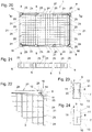
- Fig. 12 shows a view obliquely from above into the receiving space 5.
- Fig. 13 shows a view obliquely from above of the inverted box, that is to say on the bottom 3 thereof.
- Fig. 14 shows a view from above of box 1.
- Detail F from Fig. 14 is in Fig. 15 shown.
- Fig. 15 the intersection lines GG, HH and KK are shown.
- Fig. 16 shows the section along the section line GG.
- Fig. 17 shows the area L. Fig. 16 enlarged.
- the preferably wedge-shaped alignment surface 19 can be seen, which in this exemplary embodiment is formed on an outside of the base 3.
- this alignment surface 19 ensures alignment or centering of the stacked box relative to each other by the bottom 3 of the respective box 1 when stacking in stacking direction 2, as in Fig. 2 can be seen, penetrates into the upper region of the receiving space 5 of the box 1 underneath and interacts with the upper edge of the side wall 4 of the lower box 1.
- the alignment surfaces 19, which are arranged in a correspondingly distributed manner on the crate 1 or its bottom 3 the crates 1 stacked on top of one another are aligned with one another in the horizontal direction, that is in the direction normal or orthogonal to the stacking direction 2, such that the channels 8 of the crates 1 stacked one on top of the other cursed with each other.
- alignment surfaces 19, preferably wedge-shaped, are formed on the crate 1 for aligning the channels 8 of crates 1 stacked one above the other relative to one another.
- corresponding alignment surfaces 19 can of course also be shaped differently and can be formed at other locations on the respective box 1.
- Fig. 19 the lower outlet opening 10 serving as the undercut 18 and the corresponding clearance 34 in the region of the inlet opening 9 for the bolt 20 can be seen once again.
- the term inlet opening 9 and outlet opening 10 was chosen to simplify the language.
- the entry opening is the opening of the channel 8, in which a gripping device 6 is inserted into the channel 8 from above.
- the outlet opening 10 was named in such a way that when the gripping device 6 is inserted into the channel 8 from above, the gripping device 6, when it is pushed through the channel 8, at the Exit opening 10 exits channel 8 again.
- FIG. 20 shows a top view and Fig. 21 the section along the section line MM Fig. 20 .
- This serves to illustrate that the channels 8 do not necessarily have to be arranged in corner regions 16 of the box 1.
- the channels 8 can also be arranged in other areas of the side wall 4, even in the area of the side wall sections 21 arranged between the corner areas 16.
- the corner areas 16 are also formed without channels 8 can be if the channels 8 are then realized accordingly in other areas of the side wall 4.
- Fig. 22 shows a corner region 16 of a box 1, in which the channel 8 is not formed circumferentially closed.
- the channel interior cavity 12 is not closed circumferentially, that is, it is delimited by the channel delimitation wall 11 with a circumferential angle of 360 °.
- the channel boundary wall 11 delimits the channel interior cavity 12, in particular in a sectional plane 13 normal to the stacking direction 12, at least in sections over a circumferential angle 14 of at least 180 °. This is in Fig. 22 the case, as shown by the circumferential angle 14 shown.
- the 23 and 24 serve to illustrate various possibilities, such as a channel 8, in particular a circumferentially closed channel or its Channel boundary wall 11 and its channel cavity 12 can be formed.
- the channel interior cavity 12 of the respective channel 8 has a circular cross section everywhere, seen in a corresponding sectional plane 13 normal to the stacking direction 2.
- the channel interior cavity 12 is formed by two truncated cones meeting in a constriction area 35, while the channel interior cavity 12 in the variant according to FIG Fig. 24 has a circular cylindrical shape throughout.
- the constriction area 35 in the variant according to Fig. 23 can serve, for example, to fix a correspondingly designed gripping device 6 in the respective channel 8 in a form-fitting manner.
- the constriction area 35 is thus another possibility for realizing the undercut 18 already discussed above.
- the stackable crates 1 provide that the side wall 4 is in a plan view on the crate 1 has a, preferably rectangular, basic shape with, preferably four, corner regions 16 and side wall sections 21 running between the corner regions 16, the side wall sections 21 running between the corner regions 16 each having an upper side 22 of the side wall section inclined at least in regions obliquely to the stacking direction 2 21 and an oppositely arranged underside 23 of the side wall section 21 are delimited, whereby on the side wall sections 21 on the upper sides 22 of the side wall sections 21 in each case adjacent to at least one region 24 of the respective upper which is inclined obliquely to the stacking direction 2 Side 22, preferably between two of these obliquely inclined areas 24 of the respective upper side 22, contact surfaces 25 protruding beyond this or these obliquely inclined areas 24 and / or on the
- the contact surfaces 25 are formed exclusively on the upper sides 22 of the side wall sections 21.
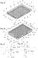
- the embodiment according to the 25 to 28 shows by way of example a variant in which the contact surfaces 27 are formed exclusively on the undersides 23 of the side wall sections 21.
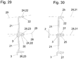
- the 29 and 30 show illustrations of a mixed form in which both contact surfaces 25 on the upper sides 22 and contact surfaces 27 on the respective lower side 23 of the respective side wall section 21 are formed.
- Fig. 6 shows the section along the section line DD Fig. 4 through the side wall sections 21 of the boxes 1 stacked on top of one another and thus in an area outside the contact surfaces 25.
- Fig. 7 shows the section along the section line EE Fig. 4 and thus the area in which the contact surfaces 25 of the respective lower box 1 formed on the respective upper side 22 of the side wall section 21 support the lower sides 23 of the box 1 arranged above.
- the section shown is the spaced arrangement of the underside 23 of the respective upper box 1 from the inclined region 24 of the Top side 22 of the side wall section 21 of the lower box 1 can be seen clearly. An air gap thus arises between the respective underside 23 and the inclined region 24 of the respective upper side 22.
- the top sides 22 of the side wall sections 21 of the respective box 1 can dry particularly quickly and well.
- the term oblique in the description of the invention is to be understood to mean that it is an angle, preferably an acute angle, which is neither a right angle nor coincides with a parallel.
- the areas 24 of the respective top side 22 of the respective side wall section 21 which are inclined to the stacking direction 2 preferably form an acute angle with the stacking direction in a range from 5 ° to 15 °, preferably from 7 ° to 10 °, a.
- the contact surfaces 25 and 27 are the only areas of the entire side wall 4, in which the stacked boxes 1 are supported on one another. This means that, in preferred embodiments, the boxes 1 stacked on top of one another do not touch in the corner regions 16 and are therefore not supported on one another in these corner regions 16.
- the contact surfaces 25 in a first plane 28 are arranged and the respective adjacent areas 24 of the respective upper sides 22 are arranged in a second plane 29, the first plane 28 and the second plane 29 enclosing an acute angle 30 with one another.
- the in Fig. 7 drawn in first plane 28 of the contact surface 25 in Fig. 6 entered again.
- the contact surfaces 25 formed on the upper sides 22 run in a plane 31 arranged normal to the stacking direction 2.
- Fig. 27 shows a section in an area in which there is no contact surface 27.
- the oblique regions 24 of the respective upper side 22 of the side wall sections 21 of the respective lower box 1 are spaced apart from the respective lower sides 23 of the side wall sections 21 of the box 1 stacked above them
- Fig. 27 clearly visible air gap in turn promotes drying of the top and bottom sides of the side wall sections.
- FIG. 28 one can see a section through the side wall sections 21 of the boxes 1 stacked on top of one another in the area of the contact surfaces 27 formed on the respective undersides 23 of the side wall sections 21. That these protrude beyond the respectively adjacent areas 26 is shown in FIG Fig. 26 good to see.
- the contact surfaces 27 are arranged in a first plane 28 and the regions 26 of the undersides 23 of the respective underside 23 which are adjacent thereto are arranged in a second plane 29, the first plane 28 and the second plane 29 form an acute angle 30 with one another.
- the first level 28 is again off Fig. 28 also in Fig. 27 registered. This embodiment shows in particular in Fig.
- the contact surfaces 27 formed on the undersides 23 in a plane 32 arranged obliquely to the stacking direction 2 can run.
- This oblique course of the contact surfaces 27 is favorable, as in FIG Fig. 28 also shown, formed at an angle which corresponds to the inclined regions 26 of the respective upper sides 22 of the side wall sections 21.
- the contact surfaces 27 lie snugly and over their entire surface on the corresponding areas 26 of the upper sides 22 of the box 1 arranged underneath, so that the boxes 1 stacked one on top of the other are stably supported.
- This embodiment according to the 25 to 28 also shows, by way of example, that in the case in which the contact surfaces 27 projecting beyond the respectively adjacent regions 26 of the underside 23 are formed on the underside 23, the regions 26 of the underside 23 respectively adjacent to the contact surfaces 27 can run in a plane 33, on which the stacking direction 2 is arranged normally, see in particular Fig. 27 .
- FIG. 27 shows analog to Fig. 6 again the situation in a section through the side walls 21 of the stacked boxes 1 outside the areas of the contact surfaces 25 and 27. In these areas, the spaced arrangement and thus the drying gap between the undersides 23 of the respective upper box 1 and the obliquely inclined regions 24 on the upper sides 22 of the side wall sections 21 of the box 1 arranged underneath.
- the angle 30 between the first plane 28 and the second plane 29 results, as in FIG Fig. 29 shown, again the same as in the other two previously described embodiments.
- the sizes of the contact surfaces 25 and 27 and their relationship to the remaining surfaces of the upper sides 22 and lower sides 23 of the side wall sections 21 can in principle be set accordingly in accordance with the load requirements to be expected or achieved. However, it is favorable if a ratio between the sum of the areas of all contact surfaces 25 on the top sides 22 of all side wall sections 21 of box 1 on the one hand and the total area of the top sides of side wall 4 of box 1 on the other hand is in a range from 1: 5 to 1:15, preferably 1: 9 to 1:11. The same applies expediently if the contact surfaces 27 are arranged on the undersides 23 of the side walls 4.
- a ratio between the sum of the areas of all contact surfaces 27 on the undersides 23 of all the side wall sections 21 of the box 1 on the one hand and the total area of the undersides 23 of the side wall 4 of the box 1 on the other hand in a range from 1: 5 to 1: 15, preferably from 1: 9 to 1:11.
- the respective contact surface 25 or 27 has an area in the range from 75 mm 2 to 175 mm 2 , preferably from 120 mm 2 to 135 mm 2 .
- a ratio between the sum of the surfaces of all the contact surfaces 25 and 27 on the top sides 22 and / or the undersides 23 of all side wall sections 21 of the box 1 on the one hand and the total area of the upper boundary surface 17 of the bottom 3 of the box 1 on the other hand is in a range from 1: 100 to 1: 130, preferably from 1: 110 to 1: 115.
Landscapes
- Engineering & Computer Science (AREA)
- Mechanical Engineering (AREA)
- Food Science & Technology (AREA)
- Ceramic Engineering (AREA)
- Stackable Containers (AREA)
- Details Of Rigid Or Semi-Rigid Containers (AREA)
Priority Applications (1)
| Application Number | Priority Date | Filing Date | Title |
|---|---|---|---|
| HRP20231635TT HRP20231635T1 (hr) | 2018-09-19 | 2019-08-07 | Kutija koju se može naslagivati |
Applications Claiming Priority (1)
| Application Number | Priority Date | Filing Date | Title |
|---|---|---|---|
| ATA292/2018A AT521025B1 (de) | 2018-09-19 | 2018-09-19 | Stapelbare Kiste |
Publications (3)
| Publication Number | Publication Date |
|---|---|
| EP3626646A1 true EP3626646A1 (fr) | 2020-03-25 |
| EP3626646C0 EP3626646C0 (fr) | 2023-10-11 |
| EP3626646B1 EP3626646B1 (fr) | 2023-10-11 |
Family
ID=67551224
Family Applications (1)
| Application Number | Title | Priority Date | Filing Date |
|---|---|---|---|
| EP19190409.3A Active EP3626646B1 (fr) | 2018-09-19 | 2019-08-07 | Boîte empilable |
Country Status (6)
| Country | Link |
|---|---|
| EP (1) | EP3626646B1 (fr) |
| AT (1) | AT521025B1 (fr) |
| ES (1) | ES2966009T3 (fr) |
| HR (1) | HRP20231635T1 (fr) |
| HU (1) | HUE064075T2 (fr) |
| PL (1) | PL3626646T3 (fr) |
Citations (2)
| Publication number | Priority date | Publication date | Assignee | Title |
|---|---|---|---|---|
| EP1287780A2 (fr) | 2001-08-28 | 2003-03-05 | FRIES PLANUNGS- UND MARKETINGGESELLSCHAFT m.b.H. | Panier pour lave-vaisselle |
| US20180251260A1 (en) * | 2017-03-01 | 2018-09-06 | Rehrig Pacific Company | Bakery tray |
Family Cites Families (2)
| Publication number | Priority date | Publication date | Assignee | Title |
|---|---|---|---|---|
| ES2143031T3 (es) * | 1994-11-04 | 2000-05-01 | Impress Metal Packaging Gmbh | Caja de transporte. |
| US6273259B1 (en) * | 2000-05-09 | 2001-08-14 | Norseman Plastics Limited | Container |
-
2018
- 2018-09-19 AT ATA292/2018A patent/AT521025B1/de not_active IP Right Cessation
-
2019
- 2019-08-07 HU HUE19190409A patent/HUE064075T2/hu unknown
- 2019-08-07 HR HRP20231635TT patent/HRP20231635T1/hr unknown
- 2019-08-07 EP EP19190409.3A patent/EP3626646B1/fr active Active
- 2019-08-07 ES ES19190409T patent/ES2966009T3/es active Active
- 2019-08-07 PL PL19190409.3T patent/PL3626646T3/pl unknown
Patent Citations (2)
| Publication number | Priority date | Publication date | Assignee | Title |
|---|---|---|---|---|
| EP1287780A2 (fr) | 2001-08-28 | 2003-03-05 | FRIES PLANUNGS- UND MARKETINGGESELLSCHAFT m.b.H. | Panier pour lave-vaisselle |
| US20180251260A1 (en) * | 2017-03-01 | 2018-09-06 | Rehrig Pacific Company | Bakery tray |
Also Published As
| Publication number | Publication date |
|---|---|
| HUE064075T2 (hu) | 2024-02-28 |
| EP3626646C0 (fr) | 2023-10-11 |
| AT521025B1 (de) | 2019-10-15 |
| HRP20231635T1 (hr) | 2024-03-15 |
| PL3626646T3 (pl) | 2024-04-02 |
| AT521025A4 (de) | 2019-10-15 |
| EP3626646B1 (fr) | 2023-10-11 |
| ES2966009T3 (es) | 2024-04-17 |
Similar Documents
| Publication | Publication Date | Title |
|---|---|---|
| EP3636559B1 (fr) | Boîte empilable | |
| EP1754897B1 (fr) | Dispositif de stockage | |
| DE10026149C2 (de) | Stapelbarer Transportbehälter | |
| CH627987A5 (de) | Stapelbarer flaschenkasten aus kunststoff. | |
| EP3981701B1 (fr) | Agencement pourvu d'au moins deux paniers empilables | |
| EP2727854A1 (fr) | Dispositif d'orientation d'une pile de récipients | |
| DE9218718U1 (de) | Teilpalette | |
| AT526429B1 (de) | Behälter | |
| AT17270U1 (de) | Korbanordnung | |
| DE19641686C2 (de) | Stapelbarer Behälter, insbesondere Lager- und Transportbehälter sowie Behältersystem | |
| EP3626646B1 (fr) | Boîte empilable | |
| DE2104389A1 (de) | Gleichzeitig als Flaschenträger und Stapelkasten ausgebildeter Flaschenkasten | |
| EP0265581A1 (fr) | Caisse effilée gerbable | |
| DE4326176A1 (de) | Stapelbehälter | |
| DE29819420U1 (de) | Tablar o.dgl. Tragmittel | |
| DE10002202A1 (de) | Transportvorrichtung | |
| EP0585535B1 (fr) | Casier empilable en plastique | |
| EP0258549A2 (fr) | Casier à bouteilles empilable | |
| DE202004014340U1 (de) | Drehstapelbehälter | |
| EP4192751B1 (fr) | Récipient en matière plastique | |
| DE69016044T2 (de) | Flaschenkasten. | |
| DE102005021170A1 (de) | Transport- und Lagerbehälter | |
| DE202021103561U1 (de) | Stapelbare Box | |
| DE6600905U (de) | Kegelstumpffoermiger behaelter handhabungsbehaelter | |
| DE29608417U1 (de) | Stapelbarer Kunststoffbehälter für die Lagerung und den Transport von Gutstücken, insbesondere Käselaiben |
Legal Events
| Date | Code | Title | Description |
|---|---|---|---|
| REG | Reference to a national code |
Ref country code: HR Ref legal event code: TUEP Ref document number: P20231635T Country of ref document: HR |
|
| PUAI | Public reference made under article 153(3) epc to a published international application that has entered the european phase |
Free format text: ORIGINAL CODE: 0009012 |
|
| STAA | Information on the status of an ep patent application or granted ep patent |
Free format text: STATUS: THE APPLICATION HAS BEEN PUBLISHED |
|
| AK | Designated contracting states |
Kind code of ref document: A1 Designated state(s): AL AT BE BG CH CY CZ DE DK EE ES FI FR GB GR HR HU IE IS IT LI LT LU LV MC MK MT NL NO PL PT RO RS SE SI SK SM TR |
|
| AX | Request for extension of the european patent |
Extension state: BA ME |
|
| STAA | Information on the status of an ep patent application or granted ep patent |
Free format text: STATUS: REQUEST FOR EXAMINATION WAS MADE |
|
| 17P | Request for examination filed |
Effective date: 20200702 |
|
| RBV | Designated contracting states (corrected) |
Designated state(s): AL AT BE BG CH CY CZ DE DK EE ES FI FR GB GR HR HU IE IS IT LI LT LU LV MC MK MT NL NO PL PT RO RS SE SI SK SM TR |
|
| STAA | Information on the status of an ep patent application or granted ep patent |
Free format text: STATUS: EXAMINATION IS IN PROGRESS |
|
| 17Q | First examination report despatched |
Effective date: 20210318 |
|
| GRAP | Despatch of communication of intention to grant a patent |
Free format text: ORIGINAL CODE: EPIDOSNIGR1 |
|
| STAA | Information on the status of an ep patent application or granted ep patent |
Free format text: STATUS: GRANT OF PATENT IS INTENDED |
|
| INTG | Intention to grant announced |
Effective date: 20230524 |
|
| GRAS | Grant fee paid |
Free format text: ORIGINAL CODE: EPIDOSNIGR3 |
|
| GRAA | (expected) grant |
Free format text: ORIGINAL CODE: 0009210 |
|
| STAA | Information on the status of an ep patent application or granted ep patent |
Free format text: STATUS: THE PATENT HAS BEEN GRANTED |
|
| AK | Designated contracting states |
Kind code of ref document: B1 Designated state(s): AL AT BE BG CH CY CZ DE DK EE ES FI FR GB GR HR HU IE IS IT LI LT LU LV MC MK MT NL NO PL PT RO RS SE SI SK SM TR |
|
| REG | Reference to a national code |
Ref country code: GB Ref legal event code: FG4D Free format text: NOT ENGLISH |
|
| REG | Reference to a national code |
Ref country code: CH Ref legal event code: EP |
|
| REG | Reference to a national code |
Ref country code: DE Ref legal event code: R096 Ref document number: 502019009613 Country of ref document: DE |
|
| REG | Reference to a national code |
Ref country code: IE Ref legal event code: FG4D Free format text: LANGUAGE OF EP DOCUMENT: GERMAN |
|
| U01 | Request for unitary effect filed |
Effective date: 20231019 |
|
| U07 | Unitary effect registered |
Designated state(s): AT BE BG DE DK EE FI FR IT LT LU LV MT NL PT SE SI Effective date: 20231027 |
|
| REG | Reference to a national code |
Ref country code: NO Ref legal event code: T2 Effective date: 20231011 |
|
| REG | Reference to a national code |
Ref country code: GR Ref legal event code: EP Ref document number: 20240400026 Country of ref document: GR Effective date: 20240209 Ref country code: SK Ref legal event code: T3 Ref document number: E 42894 Country of ref document: SK |
|
| REG | Reference to a national code |
Ref country code: HU Ref legal event code: AG4A Ref document number: E064075 Country of ref document: HU |
|
| REG | Reference to a national code |
Ref country code: HR Ref legal event code: T1PR Ref document number: P20231635 Country of ref document: HR |
|
| PG25 | Lapsed in a contracting state [announced via postgrant information from national office to epo] |
Ref country code: IS Free format text: LAPSE BECAUSE OF FAILURE TO SUBMIT A TRANSLATION OF THE DESCRIPTION OR TO PAY THE FEE WITHIN THE PRESCRIBED TIME-LIMIT Effective date: 20240211 |
|
| REG | Reference to a national code |
Ref country code: ES Ref legal event code: FG2A Ref document number: 2966009 Country of ref document: ES Kind code of ref document: T3 Effective date: 20240417 |
|
| PG25 | Lapsed in a contracting state [announced via postgrant information from national office to epo] |
Ref country code: IS Free format text: LAPSE BECAUSE OF FAILURE TO SUBMIT A TRANSLATION OF THE DESCRIPTION OR TO PAY THE FEE WITHIN THE PRESCRIBED TIME-LIMIT Effective date: 20240211 |
|
| PG25 | Lapsed in a contracting state [announced via postgrant information from national office to epo] |
Ref country code: RS Free format text: LAPSE BECAUSE OF FAILURE TO SUBMIT A TRANSLATION OF THE DESCRIPTION OR TO PAY THE FEE WITHIN THE PRESCRIBED TIME-LIMIT Effective date: 20231011 |
|
| REG | Reference to a national code |
Ref country code: DE Ref legal event code: R097 Ref document number: 502019009613 Country of ref document: DE |
|
| PG25 | Lapsed in a contracting state [announced via postgrant information from national office to epo] |
Ref country code: SM Free format text: LAPSE BECAUSE OF FAILURE TO SUBMIT A TRANSLATION OF THE DESCRIPTION OR TO PAY THE FEE WITHIN THE PRESCRIBED TIME-LIMIT Effective date: 20231011 Ref country code: RO Free format text: LAPSE BECAUSE OF FAILURE TO SUBMIT A TRANSLATION OF THE DESCRIPTION OR TO PAY THE FEE WITHIN THE PRESCRIBED TIME-LIMIT Effective date: 20231011 |
|
| U20 | Renewal fee for the european patent with unitary effect paid |
Year of fee payment: 6 Effective date: 20240709 |
|
| PLBE | No opposition filed within time limit |
Free format text: ORIGINAL CODE: 0009261 |
|
| STAA | Information on the status of an ep patent application or granted ep patent |
Free format text: STATUS: NO OPPOSITION FILED WITHIN TIME LIMIT |
|
| REG | Reference to a national code |
Ref country code: HR Ref legal event code: ODRP Ref document number: P20231635 Country of ref document: HR Payment date: 20240718 Year of fee payment: 6 |
|
| 26N | No opposition filed |
Effective date: 20240712 |
|
| PG25 | Lapsed in a contracting state [announced via postgrant information from national office to epo] |
Ref country code: MC Free format text: LAPSE BECAUSE OF FAILURE TO SUBMIT A TRANSLATION OF THE DESCRIPTION OR TO PAY THE FEE WITHIN THE PRESCRIBED TIME-LIMIT Effective date: 20231011 |
|
| REG | Reference to a national code |
Ref country code: HR Ref legal event code: ODRP Ref document number: P20231635 Country of ref document: HR Payment date: 20250721 Year of fee payment: 7 |
|
| U20 | Renewal fee for the european patent with unitary effect paid |
Year of fee payment: 7 Effective date: 20250714 |
|
| PGFP | Annual fee paid to national office [announced via postgrant information from national office to epo] |
Ref country code: HU Payment date: 20250731 Year of fee payment: 7 |
|
| PGFP | Annual fee paid to national office [announced via postgrant information from national office to epo] |
Ref country code: ES Payment date: 20250916 Year of fee payment: 7 |
|
| PGFP | Annual fee paid to national office [announced via postgrant information from national office to epo] |
Ref country code: GR Payment date: 20250820 Year of fee payment: 7 Ref country code: NO Payment date: 20250819 Year of fee payment: 7 |
|
| PGFP | Annual fee paid to national office [announced via postgrant information from national office to epo] |
Ref country code: PL Payment date: 20250716 Year of fee payment: 7 |
|
| PGFP | Annual fee paid to national office [announced via postgrant information from national office to epo] |
Ref country code: GB Payment date: 20250826 Year of fee payment: 7 |
|
| PGFP | Annual fee paid to national office [announced via postgrant information from national office to epo] |
Ref country code: HR Payment date: 20250721 Year of fee payment: 7 |
|
| PGFP | Annual fee paid to national office [announced via postgrant information from national office to epo] |
Ref country code: CH Payment date: 20250901 Year of fee payment: 7 |
|
| PGFP | Annual fee paid to national office [announced via postgrant information from national office to epo] |
Ref country code: IE Payment date: 20250819 Year of fee payment: 7 Ref country code: CZ Payment date: 20250724 Year of fee payment: 7 |
|
| PGFP | Annual fee paid to national office [announced via postgrant information from national office to epo] |
Ref country code: SK Payment date: 20250721 Year of fee payment: 7 |
|
| PG25 | Lapsed in a contracting state [announced via postgrant information from national office to epo] |
Ref country code: CY Free format text: LAPSE BECAUSE OF FAILURE TO SUBMIT A TRANSLATION OF THE DESCRIPTION OR TO PAY THE FEE WITHIN THE PRESCRIBED TIME-LIMIT; INVALID AB INITIO Effective date: 20190807 |