EP3626902A2 - Structure de paroi composite pour une construction - Google Patents
Structure de paroi composite pour une construction Download PDFInfo
- Publication number
- EP3626902A2 EP3626902A2 EP19198785.8A EP19198785A EP3626902A2 EP 3626902 A2 EP3626902 A2 EP 3626902A2 EP 19198785 A EP19198785 A EP 19198785A EP 3626902 A2 EP3626902 A2 EP 3626902A2
- Authority
- EP
- European Patent Office
- Prior art keywords
- layer
- textile
- composite wall
- concrete
- textile reinforcement
- Prior art date
- Legal status (The legal status is an assumption and is not a legal conclusion. Google has not performed a legal analysis and makes no representation as to the accuracy of the status listed.)
- Granted
Links
Images


Classifications
-
- E—FIXED CONSTRUCTIONS
- E04—BUILDING
- E04C—STRUCTURAL ELEMENTS; BUILDING MATERIALS
- E04C2/00—Building elements of relatively thin form for the construction of parts of buildings, e.g. sheet materials, slabs, or panels
- E04C2/02—Building elements of relatively thin form for the construction of parts of buildings, e.g. sheet materials, slabs, or panels characterised by specified materials
- E04C2/04—Building elements of relatively thin form for the construction of parts of buildings, e.g. sheet materials, slabs, or panels characterised by specified materials of concrete or other stone-like material; of asbestos cement; of cement and other mineral fibres
- E04C2/041—Building elements of relatively thin form for the construction of parts of buildings, e.g. sheet materials, slabs, or panels characterised by specified materials of concrete or other stone-like material; of asbestos cement; of cement and other mineral fibres composed of a number of smaller elements, e.g. bricks, also combined with a slab of hardenable material
-
- E—FIXED CONSTRUCTIONS
- E04—BUILDING
- E04C—STRUCTURAL ELEMENTS; BUILDING MATERIALS
- E04C2/00—Building elements of relatively thin form for the construction of parts of buildings, e.g. sheet materials, slabs, or panels
- E04C2/02—Building elements of relatively thin form for the construction of parts of buildings, e.g. sheet materials, slabs, or panels characterised by specified materials
- E04C2/04—Building elements of relatively thin form for the construction of parts of buildings, e.g. sheet materials, slabs, or panels characterised by specified materials of concrete or other stone-like material; of asbestos cement; of cement and other mineral fibres
- E04C2/06—Building elements of relatively thin form for the construction of parts of buildings, e.g. sheet materials, slabs, or panels characterised by specified materials of concrete or other stone-like material; of asbestos cement; of cement and other mineral fibres reinforced
-
- E—FIXED CONSTRUCTIONS
- E04—BUILDING
- E04B—GENERAL BUILDING CONSTRUCTIONS; WALLS, e.g. PARTITIONS; ROOFS; FLOORS; CEILINGS; INSULATION OR OTHER PROTECTION OF BUILDINGS
- E04B2/00—Walls, e.g. partitions, for buildings; Wall construction with regard to insulation; Connections specially adapted to walls
- E04B2/84—Walls made by casting, pouring, or tamping in situ
- E04B2/86—Walls made by casting, pouring, or tamping in situ made in permanent forms
Definitions
- the invention relates to a composite wall construction for a building.
- wall constructions must meet different requirements in terms of building physics, and for example guarantee certain load-bearing capacity values or thermal conductivity values.
- a composite component for a building by the applicant, which has a thermal barrier coating, is in the older German patent application DE 10 2016 120 947 A1 the applicant described.
- This publication discloses a composite wall which has two wall layers and an intermediate thermal insulation layer, where it is proposed to accommodate a reinforcement textile arrangement in the insulation layer in order to be able to transmit tensile forces between the two wall layers.
- the present invention does not relate to composite wall structures that have an insulating layer, but to a composite wall structure that can achieve a high load-bearing capacity.
- the composite wall construction should be as simple as possible to manufacture, also allow production as a finished part, and be designed to be transportable as a finished part in a simple manner.
- the principle of the invention is essentially to provide a composite wall construction for a building, which has a textile concrete layer and a wall layer of stone elements.
- the wall layer consists of a large number of stone elements.
- the stone elements can be made from natural stone, from artificial stone or from a suitable other stone or stone-like material.
- the stone elements are provided by masonry stones, in particular by bricks, sand-lime bricks or other masonry stones, in particular block stones.
- the wall layer can also be provided from plate-shaped stone elements, such as straps, ceramic plates, stone plates or the like.
- the individual stone elements are connected to each other by a connecting means such as mortar or grout.
- the first wall layer is therefore provided by masonry or alternatively by a stone slab wall layer.
- the wall layer runs along a flat surface, and in an alternative of the invention, along a curved surface.
- a curved surface can take any spatial shape.
- a curved surface in the sense of the invention can also have flat and curved sections.
- the second essential layer of the composite wall construction is a textile concrete layer.
- the textile concrete layer comprises a textile reinforcement, which is bordered on both sides by concrete.
- the textile concrete layer thus comprises a first concrete layer, a second concrete layer, and a textile reinforcement in between.
- the textile reinforcement consists of suitable reinforcing fibers, for example, a scrim made of carbon, glass, basalt, ceramic or aramid fibers.
- textile refers to technical textiles.
- alkali-resistant glass fibers and carbon fibers come into consideration as fiber materials.
- suitable reinforcing fibers are used, which - in contrast to the steel reinforcement in reinforced concrete - do not corrode.
- the textile fabric can consist of yarns which are composed of continuous fibers, the so-called filaments. These continuous fibers are processed on textile machines to form a lattice-like structure.
- the textile reinforcement extends along the surface along which the wall layer extends. In other words, the textile reinforcement runs parallel to the wall layer.
- the textile reinforcement is also aligned along the same plane. If, in an alternative of the invention, the wall layer is aligned along a curved surface, the textile reinforcement is also aligned along the same curved surface - and thus parallel to the surface - to the wall layer.
- the textile reinforcement runs along the entire surface along which the wall layer extends. This means that reinforcing fibers extend along the dimensions of the textile-concrete layer at least into all edge regions of the textile-concrete layer, or may also protrude beyond them.
- the dimensions of the textile reinforcements are therefore at least as large as the dimensions of the wall layer, and possibly also - at least slightly - larger.
- the invention also includes when protruding areas of the textile reinforcement protrude or protrude outwards from the textile concrete layer on one side, on several sides or on all sides.
- the textile reinforcement can be made from a single piece, or from several sections, which are particularly connected to one another, for example sewn together, woven together or glued to one another, or are connected to one another in another way while ensuring the transmission of tensile forces.
- the invention also encompasses if the textile reinforcement consists of several sections which run continuously except for slight spacing areas or up to interrupting areas.
- the invention further encompasses, in particular, if the textile reinforcement within the textile concrete layer consists of several sections, which, however, are positioned in an overlapping arrangement and form an overlap area.
- the textile reinforcement is designed to be continuous and runs continuously along the surface.
- the textile reinforcement is designed to be continuous. Continuous reinforcement can also be ensured by overlapping areas or by interruption areas.
- the invention includes if only a single mat or lattice structure is provided as textile reinforcement within the textile concrete layer. However, the invention also includes exemplary embodiments in which two or more such mats, which are connected to one another or are not connected, are arranged.
- the textile reinforcement can - before it is bordered on both sides by concrete layers - with a curing agent, e.g. B. be soaked with epoxy.
- this epoxy mass is cured before the textile reinforcement is bordered on both sides by concrete layers.
- the impregnation of the textile reinforcement can also be dispensed with.
- the textile reinforcement is optimally integrated into the concrete matrix by being surrounded by concrete on all sides.
- the composite wall construction according to the invention enables the construction of structures using extremely narrow but extremely stable walls.
- the composite wall construction according to the invention enables it to be created as a prefabricated component.
- the composite construction according to the invention can be produced efficiently in one plant, and can be transported in a simple and inexpensive manner due to the overall very narrow construction.
- the prefabricated parts can then be connected to each other on site at the construction site and the building erected.
- the invention also encompasses composite wall constructions which are manufactured on site at the construction site.
- first wall layer is provided, for example a brick masonry is built, and then the textile concrete layer is cast onto the existing masonry.
- the textile concrete layer can first be poured on site, and the second wall layer of stone elements can subsequently be bricked or glued to the textile concrete layer.
- the invention particularly includes exemplary embodiments which are produced “wet-on-wet”. This means that the stones are placed in the textile concrete layer, which is still fresh - before it hardens - or immediately after the masonry has been created from brick, if the mortar has not yet hardened, the textile concrete layer is poured directly onto the masonry or applied to it.
- this exemplary embodiment there is the advantage that no separating layer is required between the wall layer and the textile concrete layer, or that no separating layer, if any, can form, and that no additional mortar layer is required to embed the textile reinforcement.
- Applying the high-strength fine-grain concrete mass can be done like applying a plaster using a trowel.
- the fine concrete mass can also be sprayed or poured.
- the invention also encompasses composite wall constructions which comprise two wall layers, each consisting of a multiplicity of stone elements, the textile concrete layer being arranged between the two wall layers.
- the invention advantageously relates in particular to composite wall constructions which are designed as prefabricated parts.
- a die made of materials such as polyurethane, silicone, plastic, wood or metal can be used in the factory to manufacture the finished part.
- webs with a trapezoidal cross section for example, are provided at the points at which mortar joints are later to remain in the wall layer.
- the webs could consist of the material of the matrix, for example made of silicone or polyurethane, and protrude between the stones in order to make the mortar joint a little deeper and at the same time to provide a place for the safe and secure laying of the stones, for example the clinker, to specify.
- the elastic material of the webs can be suitable to compensate for dimensional tolerances of the clinker and still maintain a clean joint.
- the stones are then placed, for example, in the recesses between the webs to create the wall layer.
- the bridges form the mortar joints between the stone elements, which are slightly inward in the finished state.
- the invention also includes if the mold (die) for producing the finished part is treated with a concrete setting retarder. As a result, any soiling can be washed out more easily after removal of the molding from the mold. In particular, it can be provided that the joints between the stone elements can be washed out down to the grain, thereby imaging is possible which corresponds to the image of a conventional mortar joint.
- the composite wall construction according to the invention and the methods according to the invention for producing such a composite wall construction described below include, in particular, exemplary embodiments in which the concrete matrix surrounds and covers the textile reinforcement on all sides, the concrete in particular also penetrating the surface of the textile reinforcement in order to achieve an optimal composite effect.
- the textile concrete layer is poured.
- This formulation includes versions in which - depending on the toughness of the concrete mass used - the concrete mass is applied to the textile reinforcement or in which the concrete mass is applied to the textile reinforcement.
- the textile concrete layer has a layer thickness between 0.3 and 5 centimeters. This makes it possible to manufacture very narrow composite wall constructions, that is to say those composite wall constructions which have only a very small wall thickness, but which at the same time ensure a very high load-bearing capacity.
- the layer thickness of the textile concrete layer is particularly dependent on the application and the materials used for the textile reinforcement and the materials used for the concrete.
- the minimum layer thickness of a mortar or concrete layer is assumed according to the invention that this is at least three times the specified largest grain.
- the "Pagel” source of supply given elsewhere for a specific type of concrete or mortar, there is an approximate minimum layer thickness of 3 mm and the other concrete reference shaft “StoCretec” is an approximate minimum layer thickness of 6 mm in the sense of the invention.
- the first wall layer of masonry or parts of masonry is provided.
- the invention in particular also includes composite wall constructions in which the first wall layer represents masonry.
- the bricks can be, for example, bricks or sand-lime bricks or other conventional bricks, in particular block stones.
- the bricks can be connected to one another by means of mortar or by means of another suitable connecting means.
- the wall layer can also be provided only by parts of bricks, for example bricks divided in the middle.
- the first wall layer consists of brick parts
- prefabricated brick parts are manufactured that have a concrete backing of about 12 to 15 cm.
- the total construction thickness is therefore about 15 to 20 cm.
- a textile concrete layer thickness of only up to 4 to 5 cm is sufficient. This results in considerable weight advantages, which come into effect during transport, storage, use of materials, but also, for example, when supporting corresponding components in the building.
- a composite wall construction according to the invention is designed as a brick lintel, that is, in the manner of a brick facing, which, for. B. is placed over a window, the prefabricated brick part according to the invention can be manufactured much easier.
- Conventional brick lintels, which are made with heavy concrete, require support via, for example, stainless steel brackets on the supporting masonry.
- a prefabricated brick according to the invention in accordance with a composite wall construction according to claim 1 - depending on the dimensions - does not require the use of a corresponding bracket, but can at least be designed to be self-supporting in the case of small spans.
- the lighter prefabricated components can be handled better on the construction site, for example because the people involved, e.g. B. the bricklayer, they can be lifted and transported more easily.
- a composite wall construction according to the invention can also be used, for example, to cover a roof area.
- This offers the possibility of producing the building wall and roof in one casting, that is to say in a look, B. may appear monolithic. If the first wall layer is made of bricks, this ensures a permanent and unchanging surface, for example in contrast to a pure concrete surface that turns black and mossy over time.
- Composite wall constructions according to the invention can, for example, also span large halls with large spans, and in this way function and be used overall as a roof element of a building.
- the composite wall construction according to the invention can also be used in particular as a floor ceiling.
- composite wall construction according to the invention can also be used, for example, as a self-supporting, possibly also curved roof shell, which can also span larger spans.
- the concrete has a dry bulk density of more than 2,000 kg / m 3 .
- the textile concrete layer thus comprises concrete masses of conventional materials and with usual dry bulk densities, so that conventional concrete components can be used to accomplish the invention.
- conventional concrete is used to produce the concrete layers.
- Special high-strength fine concrete is advantageously used to produce the concrete layer.
- the high-strength fine concrete can advantageously have a maximum grain size of a maximum of 2 mm in diameter.
- fine concrete can be used with the invention, which can be obtained under the Pagel / Tudalit brands from Pagel Spezial-Beton GmbH & Co. KG, based in 45355 Essen. Repair materials that can be obtained under the brand name StoCretec TG 203 from StoCrete GmbH based in 65830 Kriftel are also suitable as concrete substitutes.
- the textile reinforcement consists of a flat, in particular limp structure.
- the structure can be, for example, a fabric, a mat, a net, a grid, a fleece, a scrim, a multi-axial scrim, an embroidery or a braid.
- the structure can in particular consist of high tensile continuous fibers. It is crucial that the Textile reinforcement consists of reinforcing fibers that can transmit tensile forces. As a result, the load-bearing capacity of the composite wall structure is greatly increased compared to conventional composite wall structures.
- the textile reinforcement is prestressed.
- the textile reinforcement can, for example, be placed in a stenter frame or in a gripping device and held under pretension.
- a tensioning frame can prestress the textile reinforcement along a spanned plane.
- the invention also includes if the textile reinforcement is prestressed outwards along a curved surface - also along a multi-curved surface. Of course, this requires a more complicated clamping device.
- the prestressing achieved by a tensioning device is applied to the textile reinforcement until it is surrounded by concrete on both sides and the concrete has hardened. Only then can the pre-stressed textile reinforcement be released from an appropriate gripping device or from a stenter. After the prestressing forces have been released, the textile reinforcement wants to contract, but is prevented by the concrete edging on both sides.
- the prestressed textile reinforcement exerts compressive forces on the concrete and prestresses the textile concrete layer consisting of textile reinforcement and concrete edging as a whole.
- Components pretensioned in this way can withstand larger loads before an initial crack occurs.
- the deformation behavior is also improved overall.
- the composite wall construction according to the invention can thus be made leaner and thus lighter by this advantageous embodiment of the invention.
- the invention also includes if not the entire textile reinforcement is subjected to a prestress, but only parts or sections or individual strands of such a textile reinforcement.
- the invention also includes if, in addition to a textile reinforcement that is not under prestress, one or more elements are arranged within the textile concrete layer that are subjected to a prestress.
- a prestressing of the textile reinforcement can also be achieved in one embodiment of a composite wall construction according to the invention in the following way: If the wall layer of the composite wall construction composed of a large number of stone elements, for example bricks, is created completely or at least partially, the wall layer can be used as a tenter frame or as Act as part of a stenter. For example, after a wall layer, in particular a brick layer, has hardened, the edges of the textile reinforcement can be fixed to the wall layer on one or two sides or on more than one side, for example concreted in or concreted in or screwed on there. The wall layer can thus act as a pressure abutment.
- the invention also includes if the textile reinforcement is fixed on one or more sides to the wall layer, and a prestress is subsequently exerted on the textile reinforcement by using tensioning elements, such as screws, hydraulic elements or under leverage, that is to say by mechanical action.
- tensioning elements such as screws, hydraulic elements or under leverage
- a prestress on the textile reinforcement in the case of fixation relative to the wall layer can also be achieved by changing the position or location of one or more elements of the wall layer.
- the invention also includes when the textile reinforcement is fixed to a plurality of components, in particular components of the wall layer, which are subjected to a change in position relative to one another and are moved, for example, apart or away from one another.
- the arrangement of a separate tenter frame can be dispensed with.
- the wall layer or the component or several components can act here as a clamping device or as part of a clamping device.
- Curved, prestressed textile reinforcements can also be realized in this way: for example, the invention includes exemplary embodiments in which a textile reinforcement is fixed at the ends of a folded or arched structure that tightens, similar to a dust jacket of a book when it is closed.
- the reinforcing fibers comprise carbon fibers and / or in particular alkali-resistant glass fibers and / or aramid fibers and / or Basalt fibers and / or ceramic fibers. Natural fibers such as sisal are also suitable for carrying out the invention. This embodiment enables conventional fiber materials to be used to provide the reinforcing fibers.
- the composite wall construction is designed as a prefabricated component. This enables the composite wall construction to be manufactured in one plant, easy transport of the narrow prefabricated components to the construction site, and a connection of different prefabricated components on site to form the wall of the structure.
- the prefabricated components can in particular comprise connection areas which are designed for connection to a connection area with an adjacent prefabricated component.
- sections of the textile reinforcement can protrude from the circumferential contours of the textile concrete layer to enable a direct connection of the textile reinforcement of a prefabricated component with the textile reinforcement of an adjacent prefabricated component.
- the prefabricated components can also have a certain contour, for example a stepped contour, in their respective field of application for connection to an adjacent prefabricated component.
- the two prefabricated components to be connected to one another are each provided with a textile reinforcement that is concreted into each component and spans the connection area.
- at least one stone element can be set as a covering layer over the connection area between two prefabricated parts, so that, as a result of the covering by the stone element or by the stone elements, the connection point or the connection area between two Finished components is no longer visible. In this way, a continuous textile reinforcement is achieved through both finished parts.
- the two prefabricated components are each step-shaped in their connection area.
- the textile concrete layer can be led to the edge of the component.
- the top row of stone elements can be left blank.
- both prefabricated components are placed next to each other, the two layers of textile concrete meet.
- the corresponding joint can be filled with mortar.
- connection area a layer of textile concrete with a textile reinforcement section extending over both components in the connection area can be concreted onto the cleared textile concrete layer of both components. Subsequently, a row with stone elements can then be applied as an outer layer in the connection area.
- a section of the textile reinforcement protrudes only from one of the two prefabricated components to be connected to one another and is connected to the second, prefabricated component to be arranged adjacent.
- two or more prefabricated components are fastened to one another, that is to say with narrow sides facing one another.
- This formulation encompasses any arrangement of a number of prefabricated components in such a way that their abutting edges or narrow sides are directed towards one another.
- These can be narrow sides of two prefabricated components arranged adjacent to one another, which are parallel to one another or below are arranged at an angle to each other, so that, for. B. also includes a fastening of several prefabricated components by the invention.
- the textile reinforcements of two prefabricated components arranged adjacent to one another are connected to one another.
- the invention includes in particular prefabricated components in which, as explained above, peripheral edge sections of the textile reinforcement of a prefabricated component protrude from the peripheral contour of the textile concrete layer. These protruding sections can be directly connected to likewise protruding textile reinforcement sections of a prefabricated component to be arranged adjacent, for example sewn, stapled, stapled or otherwise connected to one another. This enables a particularly good adhesion between two prefabricated components to be achieved.
- the composite wall construction has a second wall layer composed of a large number of stone elements.
- the textile concrete layer is arranged between the two wall layers.
- the first wall layer and the second wall layer can each consist of brick masonry.
- the bricks of the wall layer can be separated in the middle, for example.
- a composite wall construction can be provided which gives an external and internal impression of a conventional brick masonry, but has a core made of a textile concrete layer on the inside, so that such a composite wall construction has a considerably higher load-bearing capacity than a conventional brick masonry.
- At least one wall layer is designed as a decorative layer.
- the composite wall construction can consist of a textile concrete layer and a wall layer of brick masonry, the bricks used to create the brick masonry being provided by brick parts, that is to say sections of a brick.
- the brick masonry may have little or no function in the sense of contributing to the load-bearing capacity of the composite wall construction, which is provided almost exclusively by the textile concrete layer.
- the wall layer made of brick masonry functions only as a decorative layer and serves to give the inexperienced viewer the visual impression of a conventional brick masonry.
- the invention relates to a method for producing a composite wall construction.
- the invention has for its object to provide a method with which a composite wall construction can be produced in a simple manner.
- a wall layer is first provided, i. that is, bricked or created, and then poured the textile concrete layer on the created wall layer.
- the textile concrete layer is first poured. Then, if this is partially or completely hardened, a wall layer is provided and connected to the hardened textile concrete layer.
- the wall layer is attached directly to the optionally hardened textile concrete layer, e.g. B. bricked or glued to it.
- step B1) of attaching the wall layer to the textile concrete layer takes place while it is still is not or at least not fully cured.
- a "wet-on-wet” process can also be carried out here.
- Steps A) and B2), with which the wall layer is attached directly to the cast textile layer, can also be carried out “wet-on-wet”.
- the invention also encompasses methods in which the two layers, namely the textile concrete layer on the one hand and the wall layer on the other hand, are first manufactured separately and then connected to one another by a connecting layer, for example a layer of mortar or a concrete.
- a connecting layer for example a layer of mortar or a concrete.
- the textile reinforcement is subjected to a prestress before it is edged on both sides by concrete.
- the tension is released or released from the textile reinforcement only when the concrete layers which surround the textile reinforcement on both sides have hardened. In this way, a method can be provided which enables the production of particularly slim, lightweight, yet highly flexible composite wall constructions.
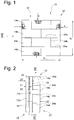
- the embodiment of the Fig. 1 shows a composite wall construction, which is designated in its entirety with 10.
- the composite wall construction is in Fig. 1 shown in isolation, and serves to erect a building 11. Such is not shown in its entirety, but in Fig. 7 indicated.
- buildings come buildings or partial building areas, e.g. B. building side walls, building floor walls, building ceiling walls, balconies, parapets, roof elements, facade parts, roof terraces, building modules, ceiling panels, vaults, shell structures or the like, all of which are encompassed by the invention.
- a composite wall construction 10 which comprises masonry of masonry. These can be conventional bricks or sand-lime bricks or other masonry stones act. Some of the individual bricks are designated as stone elements with the reference numerals 14a, 14b, 14c, 14d.
- Fig. 2 shows the composite wall construction 10 in a side view.
- the composite wall construction 10 consists of a first wall layer 13 and a textile concrete layer 15.
- the textile concrete layer 15 has a textile reinforcement 16, as well as a first concrete layer 17a and a second concrete layer 17b.
- the textile concrete layer 15 has an overall wall thickness or layer thickness 20 which corresponds approximately to the sum of the wall thickness or layer thickness 21 of the first concrete layer 17a and the layer thickness or wall thickness 22 of the second concrete layer 17b. Added to this is the layer thickness or wall thickness of the textile reinforcement 16, which, however, is negligible in comparison, and is only extremely small, for example 0.1 mm to 3 mm.
- the layer thickness 23 of the wall layer 13 can be kept as desired:
- the Fig. 2 the wall thickness 23 corresponds to the normal format of a brick 11.5 cm.
- any other desired dimensions can also be used entirely.
- bricks as bricks 14a, 14b, 14c, 14d, separate bricks, that is to say brick halves, can be used to produce the first wall layer 13. Then the layer thickness is 23 z. B. about 5.75 cm.
- the layer thickness 20 of the textile concrete layer 15 is advantageously between 0.3 cm and 5 cm.
- the layer thicknesses 21 and 22 of the concrete layer 17a, 17b are the same size in the exemplary embodiments. In other exemplary embodiments, the layer thicknesses 21, 22 can also be dimensioned differently.
- the composite wall construction 10 is therefore kept very narrow overall.
- the first wall layer 13 can be formed from stone elements 14a, 14b, 14c, 14d, which are connected to one another by a connecting means 24a, 24b, 24c.
- This can be mortar, for example.
- the composite wall construction 10 of the Fig. 1 can have any height and width dimensions y2, x2. If the composite wall construction of the Fig. 1 provides a finished component 27, the outer dimensions y2, x2 are preferably standardized. The areal area predetermined by the external dimensions y2, x2 can be up to several square meters.
- the textile reinforcement 16 is provided by a reinforcing material, for example carbon reinforcing fibers, which overall provide a grid-like or mesh-like scrim or fabric.
- Fig. 1 the edge areas of the wall layer 13 have been broken open at four points in order to make it clear that the textile reinforcement 16 Has dimensions, namely a height extension y1 and a width extension x1, which correspond to the dimensions x2, y2 of the wall layer 13.
- the textile reinforcement 16 extends continuously, in particular continuously, along the surface 12 along which the first wall layer 13 extends.
- the composite wall construction 10 can absorb particularly high tensile forces and in this way provides a high load-bearing capacity.
- the dimensions x1, y1 of the textile reinforcement 16 in height y1 and width x1 correspond to the dimensions x2, y2 of the first wall layer 13 in height y2 and width y2.
- This wording is also included, if, for example Fig. 7 indicates protruding edge regions 32a, 32b of the textile reinforcement 16 protrude from the contour of the respective prefabricated component 27, 28 in order to be able to form an overlap region 35.
- the invention comprises a composite wall construction 10 in which a textile concrete layer 15 is connected to a first wall layer 13 only on one side.
- the invention also includes composite wall constructions 10 in which a first wall layer 13 and a second wall layer 31 are provided.
- the second wall layer 31 can in turn be provided from stone elements 14e, 14f, 14g, 14h, which, in terms of their type or their shape, can correspond to the stone elements 14a, 14b, 14c, 14d of the first wall layer 13.
- the second wall layer 31 is entirely different Stone elements 14e, 14f, 14g, 14h is formed as the stone elements 14a, 14b, 14c, 14d of the first wall layer 13.
- the invention encompasses both embodiments in which the stone elements 14a, 14b, 14c, 14d of a wall layer 13 are identical, and exemplary embodiments in which the individual stone elements 14a, 14b, 14c, 14d of a wall layer 13 are different are trained.
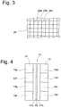
- Fig. 3 makes it clear that the textile reinforcement 16 is formed by a grid-like structure 25.
- Fig. 3 shows as an example a scrim 25, which consists of a plurality of strands of reinforcing fibers 26a, 26b, 26c, 26d, which run in the manner of warp threads and weft threads, for example, essentially rectangular or at a different angle to each other and a lattice or mesh structure form.
- the meshes can be at least partially penetrated by the still liquid concrete mass when the concrete is poured to achieve a textile concrete layer 15.
- the first wall layer 13 can also be formed by stone elements which are provided by thin plate-like elements, in particular by straps 34a, 34b, 34c, 34d.
- the first wall layer 13 then has a wall thickness 23 which is significantly smaller than in the previous exemplary embodiments.
- the straps 34a, 34b, 34c, 34d can also be connected to one another via connecting means, for example by means of mortar (indicated 24a, 24b, 24c).
- the first wall layer 13 extends along a surface 12, which is formed by a plane.
- the textile reinforcement 16 is also aligned along the same plane 12.
- the embodiment of the Fig. 6 makes it clear that the first wall layer 13 can also be aligned along a surface 12 which is curved in space.
- the surface 12 in the embodiment is FIG Fig. 6 curved in an S-shape, i.e. double-curved.
- surface 12 may also be aligned along a spherical or aspherical curvature to provide, for example, dome-shaped or spherical composite wall structures.
- a curvature of the surface 12 over two or more axes can also be provided.
- the textile reinforcement 16 is also curved along the same surface 12.
- the embodiment of the composite wall construction 10 of the Fig. 6 is so far curved in space.
- the composite wall construction 10 according to the invention can also be designed as a prefabricated component 27, 28.
- these prefabricated components 27, 28 can be connected to one another, in particular at the construction site.
- the prefabricated components 27, 28 can be fastened to one another with their respective narrow sides 29a, 29b, in particular in a butt joint.
- Any fastening means 30a, 30b can be considered for this.
- a connecting means 30a is shown, which is formed by mortar or by another hardenable connecting compound.
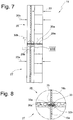
- Fig. 7 alternatively or additionally - with a broken line - a U-shaped bracket arrangement 30b which can connect the two prefabricated components 27, 28 to one another.
- Fig. 8 in a detailed representation, a further alternative embodiment of the invention, in which a connection between the two prefabricated components 27, 28 is provided by means of mortar 30a, whereby protruding edge regions 32a, 32b of the corresponding textile reinforcement 16a, 16b protrude from the respective prefabricated components 27, 28 and one Form overlap area 35.
- the protruding edge areas 32a, 32b of the textile reinforcement 16a, 16b are advantageously connected to one another, for example by separate connecting means, such as clips 33, or alternatively also by sewing, by gluing, welding, clamping, riveting, etc.
- the circumferential contour regions of the prefabricated components are complementary, in particular step-like, complementary to one another, so that two prefabricated components, for example, interlock with one another in the assembled state.
- textile reinforcement sections can advantageously be arranged at both connection areas and concreted in, in order to ensure continuous textile reinforcement, that is to say extending through the connection area between two prefabricated components.
- Fig. 9 is further shown an embodiment of a composite wall construction according to the invention, the representation of the embodiment of the Fig. 5 corresponds.
- a textile reinforcement 16 according to the embodiment Fig. 5 a plurality of textile reinforcement sections 16a and 16b are provided. These are arranged in an overlapping arrangement and form an overlap area 36 Provision of continuous textile reinforcement, since the hardened concrete can transmit the corresponding tensile forces.
- an interruption area 37 is provided in the textile reinforcement and divides the textile reinforcement into two textile reinforcement sections 16a and 16b. Continuous reinforcement is also guaranteed here.
- a textile reinforcement can be provided which has several layers or layers in order to increase the cross-section of the reinforcement in this way.
- double-layer structures in particular so-called 3-D structures, can be used, which can be obtained, for example, from V. Fraas Solutions in Textile GmbH, based in 95233 Helmbrechts.
Landscapes
- Engineering & Computer Science (AREA)
- Architecture (AREA)
- Civil Engineering (AREA)
- Structural Engineering (AREA)
- Finishing Walls (AREA)
Applications Claiming Priority (2)
| Application Number | Priority Date | Filing Date | Title |
|---|---|---|---|
| DE102018123346 | 2018-09-21 | ||
| DE102019103215.6A DE102019103215A1 (de) | 2018-09-21 | 2019-02-08 | Verbundwandkonstruktion für ein Bauwerk |
Publications (4)
| Publication Number | Publication Date |
|---|---|
| EP3626902A2 true EP3626902A2 (fr) | 2020-03-25 |
| EP3626902A3 EP3626902A3 (fr) | 2020-07-08 |
| EP3626902B1 EP3626902B1 (fr) | 2021-09-29 |
| EP3626902B8 EP3626902B8 (fr) | 2021-11-24 |
Family
ID=68158872
Family Applications (1)
| Application Number | Title | Priority Date | Filing Date |
|---|---|---|---|
| EP19198785.8A Active EP3626902B8 (fr) | 2018-09-21 | 2019-09-20 | Structure de paroi composite pour une construction |
Country Status (1)
| Country | Link |
|---|---|
| EP (1) | EP3626902B8 (fr) |
Cited By (1)
| Publication number | Priority date | Publication date | Assignee | Title |
|---|---|---|---|---|
| CN111945925A (zh) * | 2020-07-23 | 2020-11-17 | 东南大学 | 一种附加肋frp纵筋集束连接竖向预制构件 |
Citations (1)
| Publication number | Priority date | Publication date | Assignee | Title |
|---|---|---|---|---|
| DE102016120947A1 (de) | 2016-11-03 | 2018-05-03 | Peter Böhm | Verbundbauteil für ein Bauwerk |
Family Cites Families (5)
| Publication number | Priority date | Publication date | Assignee | Title |
|---|---|---|---|---|
| DD277935A1 (de) * | 1988-12-13 | 1990-04-18 | Karl Marx Stadt Tech Textil | Anordnung zur horizontalen verbindung von mauerwerksteilen mit unterschiedlicher waermedaemmung |
| WO1996023110A1 (fr) * | 1995-01-25 | 1996-08-01 | Heinz Kunert | Structure de plancher, de plafond ou de cloison assurant une tres bonne isolation thermique |
| WO2007026108A1 (fr) * | 2005-08-31 | 2007-03-08 | Yorkshire Building Services (Whitwell) Ltd | Membrane et construction immobiliere |
| DE102008040919A1 (de) * | 2008-08-01 | 2010-02-04 | MAX BÖGL Fertigteilwerke GmbH & Co. KG | Verfahren zur Herstellung eines Betonbauteiles mit einer polymergetränkten textilen Bewehrung sowie Betonbauteil mit einer polymergetränkten textilen Bewehrung |
| DE202015005729U1 (de) * | 2015-01-17 | 2015-10-08 | Johann Bergmann Gmbh & Co | Mauerwerk |
-
2019
- 2019-09-20 EP EP19198785.8A patent/EP3626902B8/fr active Active
Patent Citations (1)
| Publication number | Priority date | Publication date | Assignee | Title |
|---|---|---|---|---|
| DE102016120947A1 (de) | 2016-11-03 | 2018-05-03 | Peter Böhm | Verbundbauteil für ein Bauwerk |
Cited By (1)
| Publication number | Priority date | Publication date | Assignee | Title |
|---|---|---|---|---|
| CN111945925A (zh) * | 2020-07-23 | 2020-11-17 | 东南大学 | 一种附加肋frp纵筋集束连接竖向预制构件 |
Also Published As
| Publication number | Publication date |
|---|---|
| EP3626902B8 (fr) | 2021-11-24 |
| EP3626902A3 (fr) | 2020-07-08 |
| EP3626902B1 (fr) | 2021-09-29 |
Similar Documents
| Publication | Publication Date | Title |
|---|---|---|
| DE19711211C2 (de) | Schalungselement | |
| DE3790970C2 (de) | Fassadentafel | |
| WO2013102593A1 (fr) | Élément de construction et procédé de fabrication d'un élément de construction | |
| EP3191657B1 (fr) | Coffrage perdu en béton haute performance ou ultra haute performance | |
| DE102019103215A1 (de) | Verbundwandkonstruktion für ein Bauwerk | |
| DE102014000316A1 (de) | Hochleistungsbewehrter Beton | |
| EP0051101B1 (fr) | Plaque en ciment et procédé et dispositif pour sa fabrication | |
| DE102012109950A1 (de) | Verbundsystem zur Verstärkung von Bauteilen | |
| DE2909179C2 (de) | Verfahren zur Erhöhung der Tragfähigkeit bestehender Stahlbetonkonstruktionen wie Stahlbeton-Silos | |
| EP3626902B1 (fr) | Structure de paroi composite pour une construction | |
| DE19525508C2 (de) | Verfahren zur Verbesserung der Tragfähigkeit von Bauteilen aus Stahlbeton oder Mauerwerk | |
| EP4349554B1 (fr) | Procédé de fabrication d'une dalle en béton précontraint | |
| DE4020685C2 (de) | Vorgefertigte, transportierbare, selbsttragende Fliesentrennwand | |
| EP2297413A2 (fr) | Élément de construction semi-fini à plusieurs parois | |
| EP4388158A1 (fr) | Éléments sandwich en verre cellulaire et leur utilisation | |
| DE102019213577B4 (de) | Fertigbauelement | |
| EP1634684A2 (fr) | Procédé pour fixer des éléments de construction aux murs ou aux plafonds et construction obtenue par ce procédé | |
| DE102024111006B4 (de) | Hohldeckenplatte und Verfahren zu ihrer Herstellung | |
| DE19801305C2 (de) | Bewehrungsanordnung für Mauerwerk | |
| DE3723629C2 (fr) | ||
| DE29906967U1 (de) | Schalung | |
| DE202025107832U1 (de) | Halbfertig-Deckenelement als vorgefertigtes, transportier- und verlegbares Deckenelement für die Herstellung einer Verbunddecke durch Aufbringen von Ortbeton zur Bildung einer Ortbetonschicht | |
| AT414334B (de) | Bausteinverbund | |
| DE10121864B4 (de) | Drempelwandvorrichtung | |
| DE4025521A1 (de) | Vorgefertigte, transportierbare und selbsttragende fliesentrennwand |
Legal Events
| Date | Code | Title | Description |
|---|---|---|---|
| PUAI | Public reference made under article 153(3) epc to a published international application that has entered the european phase |
Free format text: ORIGINAL CODE: 0009012 |
|
| STAA | Information on the status of an ep patent application or granted ep patent |
Free format text: STATUS: THE APPLICATION HAS BEEN PUBLISHED |
|
| AK | Designated contracting states |
Kind code of ref document: A2 Designated state(s): AL AT BE BG CH CY CZ DE DK EE ES FI FR GB GR HR HU IE IS IT LI LT LU LV MC MK MT NL NO PL PT RO RS SE SI SK SM TR |
|
| AX | Request for extension of the european patent |
Extension state: BA ME |
|
| PUAL | Search report despatched |
Free format text: ORIGINAL CODE: 0009013 |
|
| AK | Designated contracting states |
Kind code of ref document: A3 Designated state(s): AL AT BE BG CH CY CZ DE DK EE ES FI FR GB GR HR HU IE IS IT LI LT LU LV MC MK MT NL NO PL PT RO RS SE SI SK SM TR |
|
| AX | Request for extension of the european patent |
Extension state: BA ME |
|
| RIC1 | Information provided on ipc code assigned before grant |
Ipc: E04C 2/04 20060101AFI20200604BHEP Ipc: E04C 2/06 20060101ALI20200604BHEP Ipc: E04B 2/56 20060101ALI20200604BHEP Ipc: E04B 1/76 20060101ALI20200604BHEP |
|
| STAA | Information on the status of an ep patent application or granted ep patent |
Free format text: STATUS: REQUEST FOR EXAMINATION WAS MADE |
|
| 17P | Request for examination filed |
Effective date: 20210108 |
|
| RBV | Designated contracting states (corrected) |
Designated state(s): AL AT BE BG CH CY CZ DE DK EE ES FI FR GB GR HR HU IE IS IT LI LT LU LV MC MK MT NL NO PL PT RO RS SE SI SK SM TR |
|
| REG | Reference to a national code |
Ref country code: DE Ref legal event code: R079 Ref document number: 502019002386 Country of ref document: DE Free format text: PREVIOUS MAIN CLASS: E04C0002040000 Ipc: E04B0002860000 |
|
| GRAP | Despatch of communication of intention to grant a patent |
Free format text: ORIGINAL CODE: EPIDOSNIGR1 |
|
| STAA | Information on the status of an ep patent application or granted ep patent |
Free format text: STATUS: GRANT OF PATENT IS INTENDED |
|
| RIC1 | Information provided on ipc code assigned before grant |
Ipc: E04B 2/86 20060101AFI20210414BHEP |
|
| INTG | Intention to grant announced |
Effective date: 20210511 |
|
| GRAS | Grant fee paid |
Free format text: ORIGINAL CODE: EPIDOSNIGR3 |
|
| GRAA | (expected) grant |
Free format text: ORIGINAL CODE: 0009210 |
|
| STAA | Information on the status of an ep patent application or granted ep patent |
Free format text: STATUS: THE PATENT HAS BEEN GRANTED |
|
| AK | Designated contracting states |
Kind code of ref document: B1 Designated state(s): AL AT BE BG CH CY CZ DE DK EE ES FI FR GB GR HR HU IE IS IT LI LT LU LV MC MK MT NL NO PL PT RO RS SE SI SK SM TR |
|
| REG | Reference to a national code |
Ref country code: GB Ref legal event code: FG4D Free format text: NOT ENGLISH |
|
| REG | Reference to a national code |
Ref country code: CH Ref legal event code: EP Ref country code: AT Ref legal event code: REF Ref document number: 1434308 Country of ref document: AT Kind code of ref document: T Effective date: 20211015 |
|
| REG | Reference to a national code |
Ref country code: DE Ref legal event code: R096 Ref document number: 502019002386 Country of ref document: DE |
|
| REG | Reference to a national code |
Ref country code: DE Ref legal event code: R081 Ref document number: 502019002386 Country of ref document: DE Owner name: THESING, MANUEL, PROF., DE Free format text: FORMER OWNERS: BOEHM, PETER, PROF., 50968 KOELN, DE; KLEPPE, MARTIN, 54579 UEXHEIM, DE; MUELLER, HELMUT, PROF., 40625 DUESSELDORF, DE; THESING, MANUEL, PROF., 46359 HEIDEN, DE Ref country code: DE Ref legal event code: R081 Ref document number: 502019002386 Country of ref document: DE Owner name: KLEPPE, MARTIN, DE Free format text: FORMER OWNERS: BOEHM, PETER, PROF., 50968 KOELN, DE; KLEPPE, MARTIN, 54579 UEXHEIM, DE; MUELLER, HELMUT, PROF., 40625 DUESSELDORF, DE; THESING, MANUEL, PROF., 46359 HEIDEN, DE Ref country code: DE Ref legal event code: R081 Ref document number: 502019002386 Country of ref document: DE Owner name: KLEPPE, BASTIAN, DE Free format text: FORMER OWNERS: BOEHM, PETER, PROF., 50968 KOELN, DE; KLEPPE, MARTIN, 54579 UEXHEIM, DE; MUELLER, HELMUT, PROF., 40625 DUESSELDORF, DE; THESING, MANUEL, PROF., 46359 HEIDEN, DE Ref country code: DE Ref legal event code: R081 Ref document number: 502019002386 Country of ref document: DE Owner name: BOEHM, PETER, PROF., DE Free format text: FORMER OWNERS: BOEHM, PETER, PROF., 50968 KOELN, DE; KLEPPE, MARTIN, 54579 UEXHEIM, DE; MUELLER, HELMUT, PROF., 40625 DUESSELDORF, DE; THESING, MANUEL, PROF., 46359 HEIDEN, DE |
|
| REG | Reference to a national code |
Ref country code: IE Ref legal event code: FG4D Free format text: LANGUAGE OF EP DOCUMENT: GERMAN |
|
| REG | Reference to a national code |
Ref country code: CH Ref legal event code: PK Free format text: BERICHTIGUNG B8 |
|
| RAP2 | Party data changed (patent owner data changed or rights of a patent transferred) |
Owner name: THESING, MANUEL Owner name: KLEPPE, BASTIAN Owner name: BOEHM, PETER Owner name: KLEPPE, MARTIN |
|
| REG | Reference to a national code |
Ref country code: LT Ref legal event code: MG9D |
|
| REG | Reference to a national code |
Ref country code: NL Ref legal event code: FP |
|
| PG25 | Lapsed in a contracting state [announced via postgrant information from national office to epo] |
Ref country code: LT Free format text: LAPSE BECAUSE OF FAILURE TO SUBMIT A TRANSLATION OF THE DESCRIPTION OR TO PAY THE FEE WITHIN THE PRESCRIBED TIME-LIMIT Effective date: 20210929 Ref country code: BG Free format text: LAPSE BECAUSE OF FAILURE TO SUBMIT A TRANSLATION OF THE DESCRIPTION OR TO PAY THE FEE WITHIN THE PRESCRIBED TIME-LIMIT Effective date: 20211229 Ref country code: HR Free format text: LAPSE BECAUSE OF FAILURE TO SUBMIT A TRANSLATION OF THE DESCRIPTION OR TO PAY THE FEE WITHIN THE PRESCRIBED TIME-LIMIT Effective date: 20210929 Ref country code: NO Free format text: LAPSE BECAUSE OF FAILURE TO SUBMIT A TRANSLATION OF THE DESCRIPTION OR TO PAY THE FEE WITHIN THE PRESCRIBED TIME-LIMIT Effective date: 20211229 Ref country code: FI Free format text: LAPSE BECAUSE OF FAILURE TO SUBMIT A TRANSLATION OF THE DESCRIPTION OR TO PAY THE FEE WITHIN THE PRESCRIBED TIME-LIMIT Effective date: 20210929 Ref country code: SE Free format text: LAPSE BECAUSE OF FAILURE TO SUBMIT A TRANSLATION OF THE DESCRIPTION OR TO PAY THE FEE WITHIN THE PRESCRIBED TIME-LIMIT Effective date: 20210929 Ref country code: RS Free format text: LAPSE BECAUSE OF FAILURE TO SUBMIT A TRANSLATION OF THE DESCRIPTION OR TO PAY THE FEE WITHIN THE PRESCRIBED TIME-LIMIT Effective date: 20210929 |
|
| PG25 | Lapsed in a contracting state [announced via postgrant information from national office to epo] |
Ref country code: LV Free format text: LAPSE BECAUSE OF FAILURE TO SUBMIT A TRANSLATION OF THE DESCRIPTION OR TO PAY THE FEE WITHIN THE PRESCRIBED TIME-LIMIT Effective date: 20210929 Ref country code: GR Free format text: LAPSE BECAUSE OF FAILURE TO SUBMIT A TRANSLATION OF THE DESCRIPTION OR TO PAY THE FEE WITHIN THE PRESCRIBED TIME-LIMIT Effective date: 20211230 |
|
| PG25 | Lapsed in a contracting state [announced via postgrant information from national office to epo] |
Ref country code: IS Free format text: LAPSE BECAUSE OF FAILURE TO SUBMIT A TRANSLATION OF THE DESCRIPTION OR TO PAY THE FEE WITHIN THE PRESCRIBED TIME-LIMIT Effective date: 20220129 Ref country code: SK Free format text: LAPSE BECAUSE OF FAILURE TO SUBMIT A TRANSLATION OF THE DESCRIPTION OR TO PAY THE FEE WITHIN THE PRESCRIBED TIME-LIMIT Effective date: 20210929 Ref country code: RO Free format text: LAPSE BECAUSE OF FAILURE TO SUBMIT A TRANSLATION OF THE DESCRIPTION OR TO PAY THE FEE WITHIN THE PRESCRIBED TIME-LIMIT Effective date: 20210929 Ref country code: PT Free format text: LAPSE BECAUSE OF FAILURE TO SUBMIT A TRANSLATION OF THE DESCRIPTION OR TO PAY THE FEE WITHIN THE PRESCRIBED TIME-LIMIT Effective date: 20220131 Ref country code: PL Free format text: LAPSE BECAUSE OF FAILURE TO SUBMIT A TRANSLATION OF THE DESCRIPTION OR TO PAY THE FEE WITHIN THE PRESCRIBED TIME-LIMIT Effective date: 20210929 Ref country code: ES Free format text: LAPSE BECAUSE OF FAILURE TO SUBMIT A TRANSLATION OF THE DESCRIPTION OR TO PAY THE FEE WITHIN THE PRESCRIBED TIME-LIMIT Effective date: 20210929 Ref country code: EE Free format text: LAPSE BECAUSE OF FAILURE TO SUBMIT A TRANSLATION OF THE DESCRIPTION OR TO PAY THE FEE WITHIN THE PRESCRIBED TIME-LIMIT Effective date: 20210929 Ref country code: AL Free format text: LAPSE BECAUSE OF FAILURE TO SUBMIT A TRANSLATION OF THE DESCRIPTION OR TO PAY THE FEE WITHIN THE PRESCRIBED TIME-LIMIT Effective date: 20210929 |
|
| REG | Reference to a national code |
Ref country code: DE Ref legal event code: R097 Ref document number: 502019002386 Country of ref document: DE |
|
| PG25 | Lapsed in a contracting state [announced via postgrant information from national office to epo] |
Ref country code: DK Free format text: LAPSE BECAUSE OF FAILURE TO SUBMIT A TRANSLATION OF THE DESCRIPTION OR TO PAY THE FEE WITHIN THE PRESCRIBED TIME-LIMIT Effective date: 20210929 Ref country code: CZ Free format text: LAPSE BECAUSE OF FAILURE TO SUBMIT A TRANSLATION OF THE DESCRIPTION OR TO PAY THE FEE WITHIN THE PRESCRIBED TIME-LIMIT Effective date: 20210929 |
|
| PLBE | No opposition filed within time limit |
Free format text: ORIGINAL CODE: 0009261 |
|
| STAA | Information on the status of an ep patent application or granted ep patent |
Free format text: STATUS: NO OPPOSITION FILED WITHIN TIME LIMIT |
|
| 26N | No opposition filed |
Effective date: 20220630 |
|
| PG25 | Lapsed in a contracting state [announced via postgrant information from national office to epo] |
Ref country code: SI Free format text: LAPSE BECAUSE OF FAILURE TO SUBMIT A TRANSLATION OF THE DESCRIPTION OR TO PAY THE FEE WITHIN THE PRESCRIBED TIME-LIMIT Effective date: 20210929 |
|
| PG25 | Lapsed in a contracting state [announced via postgrant information from national office to epo] |
Ref country code: IT Free format text: LAPSE BECAUSE OF FAILURE TO SUBMIT A TRANSLATION OF THE DESCRIPTION OR TO PAY THE FEE WITHIN THE PRESCRIBED TIME-LIMIT Effective date: 20210929 |
|
| PG25 | Lapsed in a contracting state [announced via postgrant information from national office to epo] |
Ref country code: MC Free format text: LAPSE BECAUSE OF FAILURE TO SUBMIT A TRANSLATION OF THE DESCRIPTION OR TO PAY THE FEE WITHIN THE PRESCRIBED TIME-LIMIT Effective date: 20210929 |
|
| PG25 | Lapsed in a contracting state [announced via postgrant information from national office to epo] |
Ref country code: IE Free format text: LAPSE BECAUSE OF NON-PAYMENT OF DUE FEES Effective date: 20220920 |
|
| PG25 | Lapsed in a contracting state [announced via postgrant information from national office to epo] |
Ref country code: HU Free format text: LAPSE BECAUSE OF FAILURE TO SUBMIT A TRANSLATION OF THE DESCRIPTION OR TO PAY THE FEE WITHIN THE PRESCRIBED TIME-LIMIT; INVALID AB INITIO Effective date: 20190920 |
|
| PG25 | Lapsed in a contracting state [announced via postgrant information from national office to epo] |
Ref country code: SM Free format text: LAPSE BECAUSE OF FAILURE TO SUBMIT A TRANSLATION OF THE DESCRIPTION OR TO PAY THE FEE WITHIN THE PRESCRIBED TIME-LIMIT Effective date: 20210929 Ref country code: CY Free format text: LAPSE BECAUSE OF FAILURE TO SUBMIT A TRANSLATION OF THE DESCRIPTION OR TO PAY THE FEE WITHIN THE PRESCRIBED TIME-LIMIT Effective date: 20210929 |
|
| GBPC | Gb: european patent ceased through non-payment of renewal fee |
Effective date: 20230920 |
|
| PG25 | Lapsed in a contracting state [announced via postgrant information from national office to epo] |
Ref country code: MK Free format text: LAPSE BECAUSE OF FAILURE TO SUBMIT A TRANSLATION OF THE DESCRIPTION OR TO PAY THE FEE WITHIN THE PRESCRIBED TIME-LIMIT Effective date: 20210929 |
|
| PG25 | Lapsed in a contracting state [announced via postgrant information from national office to epo] |
Ref country code: TR Free format text: LAPSE BECAUSE OF FAILURE TO SUBMIT A TRANSLATION OF THE DESCRIPTION OR TO PAY THE FEE WITHIN THE PRESCRIBED TIME-LIMIT Effective date: 20210929 |
|
| PG25 | Lapsed in a contracting state [announced via postgrant information from national office to epo] |
Ref country code: GB Free format text: LAPSE BECAUSE OF NON-PAYMENT OF DUE FEES Effective date: 20230920 |
|
| PG25 | Lapsed in a contracting state [announced via postgrant information from national office to epo] |
Ref country code: GB Free format text: LAPSE BECAUSE OF NON-PAYMENT OF DUE FEES Effective date: 20230920 |
|
| PG25 | Lapsed in a contracting state [announced via postgrant information from national office to epo] |
Ref country code: MT Free format text: LAPSE BECAUSE OF FAILURE TO SUBMIT A TRANSLATION OF THE DESCRIPTION OR TO PAY THE FEE WITHIN THE PRESCRIBED TIME-LIMIT Effective date: 20210929 |
|
| PGFP | Annual fee paid to national office [announced via postgrant information from national office to epo] |
Ref country code: DE Payment date: 20250925 Year of fee payment: 7 |
|
| PGFP | Annual fee paid to national office [announced via postgrant information from national office to epo] |
Ref country code: LU Payment date: 20250929 Year of fee payment: 7 Ref country code: NL Payment date: 20250929 Year of fee payment: 7 |
|
| PGFP | Annual fee paid to national office [announced via postgrant information from national office to epo] |
Ref country code: BE Payment date: 20250929 Year of fee payment: 7 |
|
| PGFP | Annual fee paid to national office [announced via postgrant information from national office to epo] |
Ref country code: FR Payment date: 20250929 Year of fee payment: 7 Ref country code: AT Payment date: 20250930 Year of fee payment: 7 |
|
| REG | Reference to a national code |
Ref country code: CH Ref legal event code: U11 Free format text: ST27 STATUS EVENT CODE: U-0-0-U10-U11 (AS PROVIDED BY THE NATIONAL OFFICE) Effective date: 20251025 |
|
| PGFP | Annual fee paid to national office [announced via postgrant information from national office to epo] |
Ref country code: CH Payment date: 20251025 Year of fee payment: 7 |