EP3626996A1 - Articulation élastique - Google Patents
Articulation élastique Download PDFInfo
- Publication number
- EP3626996A1 EP3626996A1 EP18787037.3A EP18787037A EP3626996A1 EP 3626996 A1 EP3626996 A1 EP 3626996A1 EP 18787037 A EP18787037 A EP 18787037A EP 3626996 A1 EP3626996 A1 EP 3626996A1
- Authority
- EP
- European Patent Office
- Prior art keywords
- inner ring
- metal wire
- elastic joint
- joint
- outer ring
- Prior art date
- Legal status (The legal status is an assumption and is not a legal conclusion. Google has not performed a legal analysis and makes no representation as to the accuracy of the status listed.)
- Pending
Links
Images
Classifications
-
- F—MECHANICAL ENGINEERING; LIGHTING; HEATING; WEAPONS; BLASTING
- F16—ENGINEERING ELEMENTS AND UNITS; GENERAL MEASURES FOR PRODUCING AND MAINTAINING EFFECTIVE FUNCTIONING OF MACHINES OR INSTALLATIONS; THERMAL INSULATION IN GENERAL
- F16F—SPRINGS; SHOCK-ABSORBERS; MEANS FOR DAMPING VIBRATION
- F16F1/00—Springs
- F16F1/36—Springs made of rubber or other material having high internal friction, e.g. thermoplastic elastomers
- F16F1/3605—Springs made of rubber or other material having high internal friction, e.g. thermoplastic elastomers characterised by their material
-
- F—MECHANICAL ENGINEERING; LIGHTING; HEATING; WEAPONS; BLASTING
- F16—ENGINEERING ELEMENTS AND UNITS; GENERAL MEASURES FOR PRODUCING AND MAINTAINING EFFECTIVE FUNCTIONING OF MACHINES OR INSTALLATIONS; THERMAL INSULATION IN GENERAL
- F16F—SPRINGS; SHOCK-ABSORBERS; MEANS FOR DAMPING VIBRATION
- F16F1/00—Springs
- F16F1/36—Springs made of rubber or other material having high internal friction, e.g. thermoplastic elastomers
- F16F1/362—Springs made of rubber or other material having high internal friction, e.g. thermoplastic elastomers made of steel wool, compressed hair, woven or non-woven textile, or like materials
-
- F—MECHANICAL ENGINEERING; LIGHTING; HEATING; WEAPONS; BLASTING
- F16—ENGINEERING ELEMENTS AND UNITS; GENERAL MEASURES FOR PRODUCING AND MAINTAINING EFFECTIVE FUNCTIONING OF MACHINES OR INSTALLATIONS; THERMAL INSULATION IN GENERAL
- F16C—SHAFTS; FLEXIBLE SHAFTS; ELEMENTS OR CRANKSHAFT MECHANISMS; ROTARY BODIES OTHER THAN GEARING ELEMENTS; BEARINGS
- F16C11/00—Pivots; Pivotal connections
- F16C11/04—Pivotal connections
- F16C11/06—Ball-joints; Other joints having more than one degree of angular freedom, i.e. universal joints
- F16C11/08—Ball-joints; Other joints having more than one degree of angular freedom, i.e. universal joints with resilient bearings
-
- F—MECHANICAL ENGINEERING; LIGHTING; HEATING; WEAPONS; BLASTING
- F16—ENGINEERING ELEMENTS AND UNITS; GENERAL MEASURES FOR PRODUCING AND MAINTAINING EFFECTIVE FUNCTIONING OF MACHINES OR INSTALLATIONS; THERMAL INSULATION IN GENERAL
- F16C—SHAFTS; FLEXIBLE SHAFTS; ELEMENTS OR CRANKSHAFT MECHANISMS; ROTARY BODIES OTHER THAN GEARING ELEMENTS; BEARINGS
- F16C2326/00—Articles relating to transporting
- F16C2326/01—Parts of vehicles in general
- F16C2326/05—Vehicle suspensions, e.g. bearings, pivots or connecting rods used therein
-
- F—MECHANICAL ENGINEERING; LIGHTING; HEATING; WEAPONS; BLASTING
- F16—ENGINEERING ELEMENTS AND UNITS; GENERAL MEASURES FOR PRODUCING AND MAINTAINING EFFECTIVE FUNCTIONING OF MACHINES OR INSTALLATIONS; THERMAL INSULATION IN GENERAL
- F16C—SHAFTS; FLEXIBLE SHAFTS; ELEMENTS OR CRANKSHAFT MECHANISMS; ROTARY BODIES OTHER THAN GEARING ELEMENTS; BEARINGS
- F16C2326/00—Articles relating to transporting
- F16C2326/01—Parts of vehicles in general
- F16C2326/06—Drive shafts
Definitions
- the object of the present invention is an elastic joint used to prevent premature wear of machines and to prevent stoppages or breakdowns, which has the characteristic of being made entirely of metal material and which has particular constructive features aimed at preventing the generation of noise and the transmission of vibrations during its operation.
- This elastic joint is applicable to all types of equipment and installations that must withstand radial, axial, torsional or conical stresses, such as: explosion engines, commercial vehicles, trains, etc., on the shaft or overarm of all types of machines or of all types of transport elements, being installed on the support shaft that connects the wheel with the engine suspension or with the vehicle chassis by means of an elastic joint; or at both ends of the shock absorbers of the vehicles; and on any other machine or installation requiring a joint.
- these joints can be subjected to forces in a single direction or to forces with vector components in various directions, such as: axial, radial, conical and torsional.
- Elastic joints comprising two concentrically arranged metal cylindrical reinforcements and a mass of elastomeric material, usually rubber, compressed between the two reinforcements, are known in the state of the art.
- European patent EP2 077 402 (HUTCHINSON, S.A.) describes a damper for an aerospace structure made up of an annular chamber with compartments, each of these compartments being filled by a wire mesh metal cushion, completing the device with a damping fluid filling the annular chamber and the interstices between the wire mesh.
- This elastic joint is complex to manufacture due to the incorporation of the damping fluid and the need to incorporate radial shaft seals or hydraulic seals to prevent fluid leakage over time.
- this joint has only axial elasticity, and does not provide suitable angular, torsional, or radial elasticity.
- the stiffness is provided by the cushion while damping is provided by fluid.
- US 2 729 442 discloses a joint with deformable cushions to be arranged between rotatory elements, formed by an outer sleeve and a square-shaped inner sleeve, between which deformable cushions are arranged.
- the elastic joint object of the invention has particular constructive features aimed at providing it with a high construction simplicity, as it is made entirely of metallic materials, being able to be used to withstand high loads and high temperatures, not experiencing deterioration with the contact of chemicals.
- this elastic joint comprises:
- These metal wire cushions preferably, have a square shape and are distributed around the intermediate sections of the inner ring, forming a plurality of contact points between said inner ring and the outer ring. These metal wire cushions can withstand high loads and, as they are metallic, provide damping without being affected by temperature.
- the intermediate sections of the inner ring may have different shapes, such as truncated cone shape or polygonal truncated pyramid shape, and different inclinations in order to provide different damping levels, always depending on the type of stress to be withstood: axial, radial, oblique or torsional.
- the intermediate sections of the inner ring have planes or recesses forming seating and stabilising areas for the metal wire cushions to withstand the torsional force.
- Both the intermediate sections of the inner ring and the intermediate portions of the outer ring are delimited at their opposite ends by protrusions that form retaining stops for the metal wire cushions in the position of use of the joint.
- the outer ring is made up of two ring pieces intended to be mounted at opposite ends of the inner ring and attached by screwing into the mounting position of the joint.
- This mounting by screwing allows varying the compressive force to which the wire cushions arranged between the inner ring and the outer ring are subjected; thus achieving a greater or lesser compaction of the aforementioned elastic wire cushions; and consequently, a variation of the deformation strength of the elastic joint facing different forces: radial, axial, conical and torsional.
- the outer surface for mounting the joint on the support to be damped is cylindrical.
- the inner ring is arranged between the intermediate sections of a cylindrical central section; the joint comprising additional metal wire cushions mounted on said central section that significantly increase the strength of the joint to radial loads.
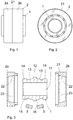
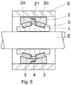
- the elastic joint of the invention comprises: an inner ring (1), an outer ring (2) and metal wire cushions (3) arranged between the two and forming damping and anti-friction means.
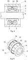
- the inner ring (1) is provided with an axial opening (11) for mounting the joint on a shaft "E", as shown in Figure 4 , and with an outer surface having: a central section (12); two opposing intermediate sections (13) having a decreasing cross-section towards opposite ends of said inner ring (1); and two end sections (14) having a smaller cross-section than the central section.
- the two intermediate sections (13) of the inner ring form zones for supporting the metal wire cushions (3), which, in the position of use of the joint shown in Figure 4 , are arranged between said inner ring (1) and the outer ring (2).
- the intermediate sections (13) of the inner ring (1) have a truncated cone configuration and are delimited by protrusions (15) forming retaining stops for the metal wire cushions (3) in the position of use of the elastic joint.
- the intermediate sections (13) have a series of recesses (16) forming seating and stabilising areas for the metal wire cushions (3).
- the outer ring (2) has a cylindrical outer surface (21) for mounting the joint on a support (S) to be damped, as shown in Figure 4 ; and an inner surface with two intermediate portions (22) of decreasing cross-section towards the opposite ends of the outer ring (2) and facing the intermediate sections (13) of the inner ring (1).
- intermediate portions (22) having a truncated cone configuration, form the contact surfaces of the outer ring (2) with the metal wire cushions (3). Said intermediate portions (22) are delimited by protrusions (23) forming retaining stops for the metal wire cushions (3).
- the outer ring (2) is formed by two annular pieces (2a, 2b) facing in an axial direction and having at opposite ends complementary threaded portions for their mutual attachment by screwing, in the position of use, as shown in Figure 4 .
- the joint in addition to the metal wire cushions (3) arranged on the intermediate sections (13) of the inner ring (1), the joint has additional metal wire cushions (4) mounted on the cylindrical central section (12) of the inner ring (1). Said additional cushions (4) make it possible to increase significantly the strength of the joint to radial loads.
Landscapes
- Engineering & Computer Science (AREA)
- General Engineering & Computer Science (AREA)
- Mechanical Engineering (AREA)
- Textile Engineering (AREA)
- Vibration Prevention Devices (AREA)
- Snaps, Bayonet Connections, Set Pins, And Snap Rings (AREA)
- Springs (AREA)
Applications Claiming Priority (2)
| Application Number | Priority Date | Filing Date | Title |
|---|---|---|---|
| ES201730618A ES2686395B2 (es) | 2017-04-16 | 2017-04-16 | Articulación elástica. |
| PCT/ES2018/070304 WO2018193141A1 (fr) | 2017-04-16 | 2018-04-14 | Articulation élastique |
Publications (2)
| Publication Number | Publication Date |
|---|---|
| EP3626996A1 true EP3626996A1 (fr) | 2020-03-25 |
| EP3626996A4 EP3626996A4 (fr) | 2021-04-07 |
Family
ID=63788263
Family Applications (1)
| Application Number | Title | Priority Date | Filing Date |
|---|---|---|---|
| EP18787037.3A Pending EP3626996A4 (fr) | 2017-04-16 | 2018-04-14 | Articulation élastique |
Country Status (6)
| Country | Link |
|---|---|
| US (1) | US11204073B2 (fr) |
| EP (1) | EP3626996A4 (fr) |
| JP (1) | JP7201661B2 (fr) |
| EA (1) | EA036543B1 (fr) |
| ES (1) | ES2686395B2 (fr) |
| WO (1) | WO2018193141A1 (fr) |
Families Citing this family (4)
| Publication number | Priority date | Publication date | Assignee | Title |
|---|---|---|---|---|
| EP3855042B1 (fr) | 2020-01-27 | 2023-10-11 | Hutchinson Stop-Choc GmbH & Co.KG | Palier métallique élastique |
| DE102020102509A1 (de) * | 2020-01-31 | 2021-08-05 | Weber-Hydraulik Gmbh | Fahrzeugkabinenlager und Kippvorrichtung mit einem Fahrzeugkabinenlager |
| ES2906523B2 (es) | 2020-10-14 | 2022-09-08 | Tejasa Tc S L L | Acoplamiento elastico |
| EP4180688A1 (fr) * | 2021-11-12 | 2023-05-17 | Hutchinson Stop-Choc GmbH & Co.KG | Dispositif d'amortissement de vibrations destiné à amortir les vibrations entre deux pièces mécaniques |
Family Cites Families (23)
| Publication number | Priority date | Publication date | Assignee | Title |
|---|---|---|---|---|
| US890106A (en) * | 1907-08-08 | 1908-06-09 | David L Tschantz | Roller-bearing. |
| FR982035A (fr) * | 1943-06-02 | 1951-06-04 | Perfectionnements apportés aux systèmes du genre de ceux comportant un élement de gomme travaillant entre deux armatures et aux procédés pour les établir | |
| US2658710A (en) * | 1950-05-04 | 1953-11-10 | Robinson Aviat Inc | Vibration isolation unit |
| US2729442A (en) | 1951-10-23 | 1956-01-03 | Hermann J Neidhart | Resilient devices having deformable cushions |
| US3073557A (en) * | 1961-10-10 | 1963-01-15 | Robinson Technical Products In | Shock and vibration isolating mountings for aircraft engines and the like |
| US3250502A (en) * | 1963-03-14 | 1966-05-10 | Robinson Technical Products In | Shock and vibration isolating support |
| US3390709A (en) * | 1965-11-29 | 1968-07-02 | Lord Corp | Resilient mounting |
| CA1151626A (fr) * | 1980-04-11 | 1983-08-09 | Leon L. Hulett | Support antivibration |
| JPS5943645B2 (ja) * | 1980-08-04 | 1984-10-23 | エヌ・テ−・エヌ東洋ベアリング株式会社 | 無給油球面すべり軸受及びその製造方法 |
| DE3527213A1 (de) * | 1985-07-30 | 1987-02-12 | Witzenmann Metallschlauchfab | Verbindung zweier rohre einer leitung fuer heisse medien |
| US4892444A (en) * | 1987-02-24 | 1990-01-09 | Dunlop Limited A British Company | Resilient unit |
| FR2642121B1 (fr) * | 1989-01-24 | 1991-04-12 | Caoutchouc Manuf Plastique | Articulation elastique a limitation d'excentrage |
| IT1248852B (it) * | 1990-06-14 | 1995-01-30 | Pirelli Sistemi Antivibranti | Snodo elastico |
| US5133578A (en) * | 1991-03-08 | 1992-07-28 | Ltv Energy Products Company | Flexible joint with non-diffusive barrier |
| FR2735831B1 (fr) * | 1995-06-21 | 1997-08-22 | Hutchinson | Support elastique pour masse vibrante |
| DE19634215C2 (de) * | 1996-08-24 | 2000-11-09 | Porsche Ag | Zentrallager für eine Hinterachse eines Kraftfahrzeuges |
| US7954793B2 (en) * | 2006-12-08 | 2011-06-07 | Enidine, Inc. | Elastomeric isolator |
| DE102006058172A1 (de) * | 2006-12-09 | 2008-06-12 | Bayerische Motoren Werke Ag | Wälzlager mit Drahtkissenlagerkörper |
| FR2926122A1 (fr) | 2008-01-03 | 2009-07-10 | Hutchinson Sa | Amortisseur de vibrations notamment pour structure aerospatiale |
| US7967282B2 (en) * | 2008-10-23 | 2011-06-28 | Honeywell International Inc. | Vibration isolators |
| EP2899414A1 (fr) * | 2014-01-23 | 2015-07-29 | Siemens Aktiengesellschaft | Palier amorti d'arbre de rotor |
| KR102760710B1 (ko) * | 2018-07-02 | 2025-02-03 | 사이텍 인더스트리스 인코포레이티드 | 탄소 섬유 제조용 중합체 및 이로부터 제조된 탄소 섬유 |
| DE102019113895A1 (de) * | 2019-05-24 | 2020-11-26 | Bayerische Motoren Werke Aktiengesellschaft | Elastomerlager zur Anbringung eines Aggregats in einem Kraftfahrzeug |
-
2017
- 2017-04-16 ES ES201730618A patent/ES2686395B2/es active Active
-
2018
- 2018-04-14 WO PCT/ES2018/070304 patent/WO2018193141A1/fr not_active Ceased
- 2018-04-14 US US16/605,218 patent/US11204073B2/en active Active
- 2018-04-14 EP EP18787037.3A patent/EP3626996A4/fr active Pending
- 2018-04-14 JP JP2020505535A patent/JP7201661B2/ja active Active
- 2018-04-14 EA EA201992310A patent/EA036543B1/ru unknown
Also Published As
| Publication number | Publication date |
|---|---|
| EP3626996A4 (fr) | 2021-04-07 |
| EA201992310A1 (ru) | 2020-02-28 |
| US20200040957A1 (en) | 2020-02-06 |
| ES2686395B2 (es) | 2019-10-18 |
| ES2686395A1 (es) | 2018-10-17 |
| JP7201661B2 (ja) | 2023-01-10 |
| EA036543B1 (ru) | 2020-11-20 |
| US11204073B2 (en) | 2021-12-21 |
| BR112019020846A2 (pt) | 2020-04-28 |
| WO2018193141A1 (fr) | 2018-10-25 |
| JP2020516832A (ja) | 2020-06-11 |
Similar Documents
| Publication | Publication Date | Title |
|---|---|---|
| US11204073B2 (en) | Elastic joint | |
| US10352394B2 (en) | Elastomeric bushing having embedded structures for improved thermal conductivity and damping capacity | |
| CN103764417B (zh) | 具有非线性力-位移特性的隔振装置及包括该隔振装置的机动车悬架系统 | |
| US2535080A (en) | Mounting | |
| US8292218B2 (en) | Torque link with shimmy damper | |
| US20200070614A1 (en) | Method and apparatus for mitigating static loads in components connecting multiple structures | |
| EP3109506A1 (fr) | Dispositif de cylindre | |
| US20090173588A1 (en) | Vibration damper notably for an aerospace structure | |
| CN111566378A (zh) | 液压轴承衬套 | |
| EP3312097B1 (fr) | Atténuateur passif léger pour aéronefs spatiaux | |
| RU2657131C1 (ru) | Виброизолятор с тарельчатыми пружинами | |
| US20070296131A1 (en) | Impact damper | |
| US10156278B2 (en) | Dynamic damper apparatus with retaining structure | |
| EP4230889B1 (fr) | Couplage élastique | |
| US2560620A (en) | Roll-shear vibration isolation mounting | |
| US9897162B2 (en) | Two-dimensional vibration isolator | |
| US11649877B2 (en) | Elastomer spring/damper | |
| BR112019020846B1 (pt) | Junta elástica | |
| EP4674722A1 (fr) | Dispositif de protection d'essieu roulant de véhicule ferroviaire | |
| EP3948010B1 (fr) | Amortisseur et/ou absorbeur de vibration | |
| CN112762121A (zh) | 一种减振器及其设计方法 | |
| CN119712983A (zh) | 一种万向管道用的减震器 |
Legal Events
| Date | Code | Title | Description |
|---|---|---|---|
| STAA | Information on the status of an ep patent application or granted ep patent |
Free format text: STATUS: THE INTERNATIONAL PUBLICATION HAS BEEN MADE |
|
| PUAI | Public reference made under article 153(3) epc to a published international application that has entered the european phase |
Free format text: ORIGINAL CODE: 0009012 |
|
| STAA | Information on the status of an ep patent application or granted ep patent |
Free format text: STATUS: REQUEST FOR EXAMINATION WAS MADE |
|
| 17P | Request for examination filed |
Effective date: 20191029 |
|
| AK | Designated contracting states |
Kind code of ref document: A1 Designated state(s): AL AT BE BG CH CY CZ DE DK EE ES FI FR GB GR HR HU IE IS IT LI LT LU LV MC MK MT NL NO PL PT RO RS SE SI SK SM TR |
|
| AX | Request for extension of the european patent |
Extension state: BA ME |
|
| DAV | Request for validation of the european patent (deleted) | ||
| DAX | Request for extension of the european patent (deleted) | ||
| A4 | Supplementary search report drawn up and despatched |
Effective date: 20210304 |
|
| RIC1 | Information provided on ipc code assigned before grant |
Ipc: F16F 3/12 20060101ALI20210226BHEP Ipc: F16C 27/06 20060101ALI20210226BHEP Ipc: F16C 29/00 20060101ALI20210226BHEP Ipc: F16F 1/362 20060101AFI20210226BHEP |
|
| STAA | Information on the status of an ep patent application or granted ep patent |
Free format text: STATUS: EXAMINATION IS IN PROGRESS |
|
| 17Q | First examination report despatched |
Effective date: 20230209 |
|
| GRAP | Despatch of communication of intention to grant a patent |
Free format text: ORIGINAL CODE: EPIDOSNIGR1 |
|
| STAA | Information on the status of an ep patent application or granted ep patent |
Free format text: STATUS: GRANT OF PATENT IS INTENDED |
|
| INTG | Intention to grant announced |
Effective date: 20260119 |