EP3627016A1 - Soupape - Google Patents
Soupape Download PDFInfo
- Publication number
- EP3627016A1 EP3627016A1 EP18465575.1A EP18465575A EP3627016A1 EP 3627016 A1 EP3627016 A1 EP 3627016A1 EP 18465575 A EP18465575 A EP 18465575A EP 3627016 A1 EP3627016 A1 EP 3627016A1
- Authority
- EP
- European Patent Office
- Prior art keywords
- housing
- bearing bush
- recess
- valve
- plunger
- Prior art date
- Legal status (The legal status is an assumption and is not a legal conclusion. Google has not performed a legal analysis and makes no representation as to the accuracy of the status listed.)
- Withdrawn
Links
Images


Classifications
-
- F—MECHANICAL ENGINEERING; LIGHTING; HEATING; WEAPONS; BLASTING
- F02—COMBUSTION ENGINES; HOT-GAS OR COMBUSTION-PRODUCT ENGINE PLANTS
- F02D—CONTROLLING COMBUSTION ENGINES
- F02D9/00—Controlling engines by throttling air or fuel-and-air induction conduits or exhaust conduits
- F02D9/04—Controlling engines by throttling air or fuel-and-air induction conduits or exhaust conduits concerning exhaust conduits
-
- F—MECHANICAL ENGINEERING; LIGHTING; HEATING; WEAPONS; BLASTING
- F02—COMBUSTION ENGINES; HOT-GAS OR COMBUSTION-PRODUCT ENGINE PLANTS
- F02M—SUPPLYING COMBUSTION ENGINES IN GENERAL WITH COMBUSTIBLE MIXTURES OR CONSTITUENTS THEREOF
- F02M26/00—Engine-pertinent apparatus for adding exhaust gases to combustion-air, main fuel or fuel-air mixture, e.g. by exhaust gas recirculation [EGR] systems
- F02M26/65—Constructional details of EGR valves
- F02M26/66—Lift valves, e.g. poppet valves
- F02M26/67—Pintles; Spindles; Springs; Bearings; Sealings; Connections to actuators
-
- F—MECHANICAL ENGINEERING; LIGHTING; HEATING; WEAPONS; BLASTING
- F02—COMBUSTION ENGINES; HOT-GAS OR COMBUSTION-PRODUCT ENGINE PLANTS
- F02M—SUPPLYING COMBUSTION ENGINES IN GENERAL WITH COMBUSTIBLE MIXTURES OR CONSTITUENTS THEREOF
- F02M26/00—Engine-pertinent apparatus for adding exhaust gases to combustion-air, main fuel or fuel-air mixture, e.g. by exhaust gas recirculation [EGR] systems
- F02M26/65—Constructional details of EGR valves
- F02M26/66—Lift valves, e.g. poppet valves
- F02M26/68—Closing members; Valve seats; Flow passages
-
- F—MECHANICAL ENGINEERING; LIGHTING; HEATING; WEAPONS; BLASTING
- F02—COMBUSTION ENGINES; HOT-GAS OR COMBUSTION-PRODUCT ENGINE PLANTS
- F02M—SUPPLYING COMBUSTION ENGINES IN GENERAL WITH COMBUSTIBLE MIXTURES OR CONSTITUENTS THEREOF
- F02M26/00—Engine-pertinent apparatus for adding exhaust gases to combustion-air, main fuel or fuel-air mixture, e.g. by exhaust gas recirculation [EGR] systems
- F02M26/65—Constructional details of EGR valves
- F02M26/66—Lift valves, e.g. poppet valves
- F02M26/69—Lift valves, e.g. poppet valves having two or more valve-closing members
-
- F—MECHANICAL ENGINEERING; LIGHTING; HEATING; WEAPONS; BLASTING
- F16—ENGINEERING ELEMENTS AND UNITS; GENERAL MEASURES FOR PRODUCING AND MAINTAINING EFFECTIVE FUNCTIONING OF MACHINES OR INSTALLATIONS; THERMAL INSULATION IN GENERAL
- F16K—VALVES; TAPS; COCKS; ACTUATING-FLOATS; DEVICES FOR VENTING OR AERATING
- F16K11/00—Multiple-way valves, e.g. mixing valves; Pipe fittings incorporating such valves
- F16K11/02—Multiple-way valves, e.g. mixing valves; Pipe fittings incorporating such valves with all movable sealing faces moving as one unit
- F16K11/04—Multiple-way valves, e.g. mixing valves; Pipe fittings incorporating such valves with all movable sealing faces moving as one unit comprising only lift valves
-
- F—MECHANICAL ENGINEERING; LIGHTING; HEATING; WEAPONS; BLASTING
- F02—COMBUSTION ENGINES; HOT-GAS OR COMBUSTION-PRODUCT ENGINE PLANTS
- F02D—CONTROLLING COMBUSTION ENGINES
- F02D41/00—Electrical control of supply of combustible mixture or its constituents
- F02D41/0025—Controlling engines characterised by use of non-liquid fuels, pluralities of fuels, or non-fuel substances added to the combustible mixtures
- F02D41/0047—Controlling exhaust gas recirculation [EGR]
- F02D41/0077—Control of the EGR valve or actuator, e.g. duty cycle, closed loop control of position
Definitions
- a valve for opening and closing an exhaust pipe is specified.
- Valves for opening and closing an exhaust pipe are used in motor vehicles.
- the tightness with which the valve can close the line is important for the function of such valves. In the case of gases in particular, achieving a low leak rate is very time-consuming.
- the drive of a tappet of the valve is typically formed by an electric motor and a gear.
- the gear serves to convert the rotary movement of the electric motor into a translatory movement so that the tappet connected to the gear can be moved linearly.
- the plunger must be guided axially for this.
- a valve for opening and closing an exhaust pipe has a housing.
- the valve has plungers arranged in the housing.
- the tappet can be coupled to a drive at a first end.
- the plunger is designed to be moved along a longitudinal axis of the plunger.
- the valve has a valve seat arranged in the housing.
- the valve seat delimits an opening.
- the valve has a closing body.
- the closing body is connected to the plunger.
- the closing body is adjustable between an open position and a closed position. The opening is released in the open position. In the closed position, the closing body lies on the valve seat and seals the opening.
- the valve has a bearing bush for guiding the tappet.
- a second end of the plunger opposite the first end is in the Bearing bush arranged.
- the bearing bush has an elastic element. The elastic element exerts a force transversely to the longitudinal axis on the plunger.
- the bearing bush enables a relative movement of the tappet to the bearing bush along the longitudinal direction.
- the plunger is guided in the bearing bush.
- the bearing bush enables axial movement and guides the plunger in the radial direction.
- the elastic element also allows the ram to be slightly inclined. Radial forces are absorbed by the bearing bush during operation.
- the bearing bush and the valve with the bearing bush are easy to assemble and can be assembled in particular with just a few procedural steps.
- the bearing bush enables the tappet to move with comparatively little friction.
- the bearing bush is not very sensitive to tappet tolerances.
- the elastic element has a spring in order to exert the force.
- the spring for example a helical spring, is arranged in the bearing bush.
- the coil spring is in particular aligned radially to the tappet.
- the spring is designed to act on the tappet in the radial direction.
- the elastic element has a ball which is arranged between the spring and the plunger.
- the spring is designed to press the ball against the plunger in the radial direction.
- the ball enables a low-friction relative movement of the tappet to the bearing bush. Little or no sliding friction occurs.
- the contact between the plunger and the bearing bush is realized by means of the ball. Thus, rolling friction occurs in operation that is lower than conventional sliding friction.
- the bearing bush has a bearing housing.
- the bearing housing surrounds a first one Recess along the longitudinal axis.
- the bearing housing surrounds a second recess transverse to the longitudinal axis.
- the plunger is arranged in the first recess.
- the elastic element is arranged in the second recess.
- the bearing bush can thus be implemented as an independent component.
- the bearing housing is in particular formed separately from the valve housing.
- the second recess completely penetrates a housing wall of the bearing housing.
- the bearing bush has a cover for the second recess. From the inside out, the ball is first arranged in the second recess, then the spring and then the cover. The cover covers the second recess on the outside. As a result, the spring is biased. This enables simple manufacture and the bearing bush can be designed as a separate component.
- the second recess has a taper in the inward direction in order to limit movement of the elastic element in the inward direction. This prevents the ball from falling out of the second recess even if the tappet is not arranged in the first recess. This enables easy transport and assembly of the valve.
- the housing has a receptacle for the bearing bush.
- the bearing bush is fixed in the holder.
- the bearing bush is thus held stable relative to the other components of the valve.
- the guide of the tappet is thus designed to be stable on the valve.
- the housing has a lock for the bearing bush in order to block axial movement of the bearing bush relative to the housing.
- the lock is formed by means of a material deformation of the housing.
- the housing is after the bearing bush in the receptacle was plastically deformed to block axial displacement of the bearing bush.
- the receptacle is arranged in a housing cover of the housing.
- the housing cover is fixed to a housing body of the housing. A simple and stable arrangement of the bearing bush is thus realized.
- the bearing bush has a plurality of elastic elements.
- the elastic elements are all constructed identically.
- the bearing bush has four elastic elements, two of which are arranged opposite each other. More or less than four bearing bushes are also possible.
- valve described is particularly suitable for linear valves in which the tappet is moved linearly in one direction, in particular its longitudinal direction.
- the valve can also have a further valve seat with a further valve opening (double linear valve), which can be closed or released at the same time as the first valve opening by the tappet movement by means of a corresponding closing body.
- the valve can thus be designed as a double linear valve or with only a single closing body as a single linear valve.
- the valve can be used in an exhaust gas recirculation system of a motor vehicle to open and close the exhaust pipe of the motor vehicle.
- an exhaust gas recirculation system of a motor vehicle has the valve.
- FIG. 1 shows a valve 100 according to an embodiment for opening and closing an exhaust pipe.
- the valve 100 in Figure 1 has a housing 1 in which an electric motor 2 is arranged. By means of a gear 3, the rotary movement of the electric motor 2 is converted into a linear movement of a tappet 4.
- the tappet 4 can be coupled to the transmission at a first end 201.
- a sensor 5 is arranged on the transmission 3, which cooperates with a magnet attached to the tappet 4.
- the tappet 4 extends from the gear chamber 6 into a valve chamber 7, the tappet 4 being mounted at two points 8.
- the valve chamber 7 consists of three partial chambers 7a, 7b, 7c, which are located one behind the other and are each separated from one another by a valve seat 9.
- valve 100 according to an exemplary embodiment of the invention is described below, which has a further development of the bearing on a second end 202 of the tappet 4 facing away from the drive.
- the valve 100 may have the characteristics of Figure 1 have the described configuration.
- the valve 100 described is to be understood as an example and, alternatively, can also have other configurations, without there being any restrictions for the following description of the exemplary embodiment of the invention.
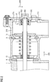
- FIG. 2 shows a sectional view of the valve 100.
- the tappet 4 with two closing bodies 10 is arranged in the housing 1 and is axially movable along the longitudinal axis 205.
- the housing 1 has a housing body 216 in which two valve seats 9 are arranged.
- the tappet 4 is held and guided at point 8 by means of a bearing bush 200.
- the bearing bush 200 enables the tappet 4 to move axially relative to the housing 1 and relative to the bearing bush 200.
- the bearing bush 200 is designed to absorb radial forces transverse to the longitudinal axis 205.
- the bearing bush 200 has, in particular, an elastic element 203 or a plurality of elastic elements 203.
- the elastic element 203 is in direct contact with the plunger 4.
- the elastic element 203 exerts a force 204 in the radial direction on the plunger 4.
- the plunger 4 is thus held radially at its second end 202 in the bearing bush.
- the second end 202 faces away from the first end 201
- the housing 1 has a housing cover 215.
- the housing cover can be fixed on the housing body 216, around the valve chambers 7 to train.
- the bearing bush 200 is fixed in a receptacle 213, which is formed by the housing cover 215.
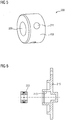
- FIG. 3 shows components of the bearing bush 200 according to an embodiment.
- the bearing bush 200 has a bearing housing 208.
- the bearing housing 208 is in particular formed separately from the housing 1.
- the bearing housing 208 has a first recess 209.
- the first recess 209 extends along the longitudinal direction 205.
- the first recess 209 is designed to receive the tappet 4. In operation, the tappet 4 moves in the first recess 209 along the longitudinal direction 205.
- the bearing housing 208 has a second recess 210.
- the second recess 210 is formed transversely to the longitudinal axis 205.
- the bearing housing 208 has four second recesses 210. More or fewer than four second recesses 210 are also possible.
- the second recess 210 extends through a housing wall 217 from the outside inwards to the first recess 209.
- the second recess 210 has a taper 212.
- the radius of the second recess 210 decreases at the taper 212.
- the bearing bush 200 has a ball 207.
- the bearing bush 200 has a ball 207 for every second recess 210.
- the ball can be arranged in the second recess 210.
- the bearing bush 200 has a spring 206.
- the spring is in particular a spiral spring.
- the bearing bush 200 in particular has a spring 206 for each ball 207.
- the spring 206 can be arranged in the second recess 210.
- the bearing bush 200 has a cover 211.
- the bearing bush 200 has its own cover 211 for each second recess 210.
- the cover is designed to close off the second recess 210 to the outside.
- Figure 4 shows a schematic representation of the bearing bush 200 in the operational state.
- the ball 207 is arranged in the second recess 210, so that it projects at least partially into the first recess 209. Penetration of the ball 207 from the second recess 210 completely into the first recess 209 is blocked by means of the taper 211.
- the spring 206 is arranged between the cover 211 and the ball 207 and thus acts the force 204 on the ball in the direction of the inside of the bearing housing 208.
- the cover 211 is fixedly connected to the bearing housing 208, so that the spring 206 is preloaded between the Cover 211 and the ball 207 is possible.
- Figure 5 shows a perspective view of the bearing bush 200.
- the bearing bush 200 has the shape of a hollow cylinder.
- the second recesses 210 are closed to the outside with respective covers 211.
- the first recess 209 is provided in the center.
- Figure 6 shows the bearing bush 200 and the associated receptacle 213 in the housing cover 215.
- the outer radius of the bearing bush 200 is in particular at least slightly larger than the inner diameter of the receptacle 213.
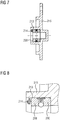
- the bearing bush 200 can be fixed in the receptacle 213 by pressing, as in Figure 7 is shown. the bearing bush 200 is thus held on the housing cover 215 and thus on the housing 1 by means of an interference fit.
- a lock 214 is provided, as in particular in FIG Figure 8 shown.
- the locking is in particular by means of a plastic Deformation of part of the housing cover 215 is formed. for example, part of the material of the housing cover 215 is deformed such that it projects radially over the bearing housing 208 of the bearing bush 200.
- the lock 214 forms a stop for the bearing housing 8 in the axial direction. Thus, movement of the bearing bush 200 in the axial direction is blocked.
- the bearing bush 200 continuously acts on the tappet 4 in the radial direction by means of the elastic elements 203.
- the plunger 4 is thus reliably held and guided in the radial direction. No play and no tolerances have to be taken into account in order to support the second end 202 of the plunger 4. Slight inclinations and / or tilting of the tappet 4 can also be accommodated by the bearing bush 200, since the elastic elements 203 are movable and elastic in the radial direction transverse to the longitudinal axis 205.
- the valve 100 with the bearing bush 200 enables the second end 202 to be supported with comparatively few parts and thus with a comparatively simple and therefore quick assembly.
- the bearing at point 8 on the side facing away from the electric motor 2 and the transmission 3 is fixed relative to the housing 1. In operation, rolling friction mainly occurs on ball 207 and sliding friction is avoided. Reliable operation is therefore possible.
- the ball 207 is in particular a metal ball.
- the cover 211 is connected to the bearing housing 208 in particular by means of an interference fit.
- the ball 207 is pressed against the inside of the second recess 210 in the direction of the first recess 209 and is held by the taper 212. It is possible to first fix the bearing bush 200 separately from the other components on the housing cover 215 and then the housing cover 215 to be connected together with the bearing bush 200 to the remaining components of the valve 100.
- the plunger 4 is introduced into the first recess 209 and comes into contact with the balls 207.
- the balls 207 are radially movable.
- the balls 207 are moved radially as a function of a deviation of the longitudinal axis 205 of the tappet 4 and a longitudinal axis of the first recess 209. A movement in the direction of the cover 209 compresses the spring 20 and thereby compensates for the deviation.
- the bearing bush 200 is easy to manufacture and has a reliable compensation of axis deviations during operation.
Landscapes
- Engineering & Computer Science (AREA)
- General Engineering & Computer Science (AREA)
- Mechanical Engineering (AREA)
- Chemical & Material Sciences (AREA)
- Combustion & Propulsion (AREA)
- Magnetically Actuated Valves (AREA)
Priority Applications (1)
| Application Number | Priority Date | Filing Date | Title |
|---|---|---|---|
| EP18465575.1A EP3627016A1 (fr) | 2018-09-19 | 2018-09-19 | Soupape |
Applications Claiming Priority (1)
| Application Number | Priority Date | Filing Date | Title |
|---|---|---|---|
| EP18465575.1A EP3627016A1 (fr) | 2018-09-19 | 2018-09-19 | Soupape |
Publications (1)
| Publication Number | Publication Date |
|---|---|
| EP3627016A1 true EP3627016A1 (fr) | 2020-03-25 |
Family
ID=63965588
Family Applications (1)
| Application Number | Title | Priority Date | Filing Date |
|---|---|---|---|
| EP18465575.1A Withdrawn EP3627016A1 (fr) | 2018-09-19 | 2018-09-19 | Soupape |
Country Status (1)
| Country | Link |
|---|---|
| EP (1) | EP3627016A1 (fr) |
Citations (13)
| Publication number | Priority date | Publication date | Assignee | Title |
|---|---|---|---|---|
| BE532135A (fr) * | ||||
| US2910267A (en) * | 1955-08-09 | 1959-10-27 | Hydra Power Corp | Valve sealing structure |
| US3107547A (en) * | 1961-05-03 | 1963-10-22 | New York Air Brake Co | Detent |
| US3528638A (en) * | 1968-05-23 | 1970-09-15 | Caterpillar Tractor Co | Detent for valves with automatic release means |
| US3602245A (en) * | 1970-02-26 | 1971-08-31 | Abex Corp | Universal detent positioner |
| US3986701A (en) * | 1975-01-06 | 1976-10-19 | Caterpillar Tractor Co. | Spade-like detent for hydraulic control valve |
| EP0952331A2 (fr) * | 1998-04-21 | 1999-10-27 | Pierburg Aktiengesellschaft | Soupape de recirculation de gaz d'échappement |
| EP0990826A1 (fr) * | 1998-04-23 | 2000-04-05 | Mitsubishi Denki Kabushiki Kaisha | Vanne de regulation |
| EP1018599A1 (fr) * | 1998-05-27 | 2000-07-12 | Mitsubishi Denki Kabushiki Kaisha | Clapet anti-retour pour gaz d'echappement |
| WO2009125526A1 (fr) * | 2008-04-08 | 2009-10-15 | 三菱電機株式会社 | Soupape de recirculation de gaz d'échappement et procédé de production de soupape de recirculation de gaz d'échappement |
| WO2010018650A1 (fr) * | 2008-08-13 | 2010-02-18 | 三菱電機株式会社 | Dispositif de soupape de circulation des gaz d’échappement |
| DE102015111461A1 (de) * | 2015-05-07 | 2016-11-10 | BorgWarner Esslingen GmbH | Abgasrückführventil und Verfahren zur Verbesserung eines solchen Ventils |
| US20160369912A1 (en) * | 2015-06-17 | 2016-12-22 | Mathena, Inc. | Electric-actuated choke apparatus and methods |
-
2018
- 2018-09-19 EP EP18465575.1A patent/EP3627016A1/fr not_active Withdrawn
Patent Citations (13)
| Publication number | Priority date | Publication date | Assignee | Title |
|---|---|---|---|---|
| BE532135A (fr) * | ||||
| US2910267A (en) * | 1955-08-09 | 1959-10-27 | Hydra Power Corp | Valve sealing structure |
| US3107547A (en) * | 1961-05-03 | 1963-10-22 | New York Air Brake Co | Detent |
| US3528638A (en) * | 1968-05-23 | 1970-09-15 | Caterpillar Tractor Co | Detent for valves with automatic release means |
| US3602245A (en) * | 1970-02-26 | 1971-08-31 | Abex Corp | Universal detent positioner |
| US3986701A (en) * | 1975-01-06 | 1976-10-19 | Caterpillar Tractor Co. | Spade-like detent for hydraulic control valve |
| EP0952331A2 (fr) * | 1998-04-21 | 1999-10-27 | Pierburg Aktiengesellschaft | Soupape de recirculation de gaz d'échappement |
| EP0990826A1 (fr) * | 1998-04-23 | 2000-04-05 | Mitsubishi Denki Kabushiki Kaisha | Vanne de regulation |
| EP1018599A1 (fr) * | 1998-05-27 | 2000-07-12 | Mitsubishi Denki Kabushiki Kaisha | Clapet anti-retour pour gaz d'echappement |
| WO2009125526A1 (fr) * | 2008-04-08 | 2009-10-15 | 三菱電機株式会社 | Soupape de recirculation de gaz d'échappement et procédé de production de soupape de recirculation de gaz d'échappement |
| WO2010018650A1 (fr) * | 2008-08-13 | 2010-02-18 | 三菱電機株式会社 | Dispositif de soupape de circulation des gaz d’échappement |
| DE102015111461A1 (de) * | 2015-05-07 | 2016-11-10 | BorgWarner Esslingen GmbH | Abgasrückführventil und Verfahren zur Verbesserung eines solchen Ventils |
| US20160369912A1 (en) * | 2015-06-17 | 2016-12-22 | Mathena, Inc. | Electric-actuated choke apparatus and methods |
Similar Documents
| Publication | Publication Date | Title |
|---|---|---|
| DE102015109474A1 (de) | Umschaltventil und Pleuel mit einem Umschaltventil | |
| DE112022004351T5 (de) | Magnetventil | |
| DE102011087103A1 (de) | Geberzylinder | |
| DE102019102253A1 (de) | Antriebsvorrichtung für ein Verschlusselement eines Kraftfahrzeugs | |
| EP3628853B1 (fr) | Soupape | |
| EP3627016A1 (fr) | Soupape | |
| EP4172519A1 (fr) | Dispositif de soupape comprenant une soupape installée dans une douille de soupape | |
| DE102011084850A1 (de) | Anordnung zur Lagerung einer Nockenrollenachse | |
| DE102021100352B4 (de) | Ventil mit einem sich entlang einer Ventilachse erstreckendem Gehäusekörper und einem Stößel | |
| EP2377132A1 (fr) | Élément d'actionnement d'une unité de commande électromagnétique d'une soupape hydraulique | |
| EP3085921B1 (fr) | Bielle comprenant une soupape d'inversion | |
| EP2966281B1 (fr) | Dispositif de couplage | |
| DE102019218400B4 (de) | Ventilkegel und Lasthalteventil mit Ventilkegel | |
| DE102016121188A1 (de) | Stellantrieb für ein Kraftfahrzeug | |
| EP1421308A1 (fr) | Clapet anti-retour de pompe | |
| EP3628852B1 (fr) | Soupape et procédé de fabrication d'une soupape | |
| EP1564450B1 (fr) | Dispositif d'arrêt pour le passage de vitesses | |
| DE102017106939A1 (de) | Pleuel für eine Brennkraftmaschine mit variabler Verdichtung sowie Rückschlagventil für ein Pleuel für eine Brennkraftmaschine mit variabler Verdichtung | |
| DE102017102777A1 (de) | Nockenwellenversteller mit Steuerventil zum Einstellen einer Verriegelungsvorrichtung | |
| DE102016204716A1 (de) | Schaltbarer Stabilisator für ein Kraftfahrzeug | |
| DE19956839A1 (de) | Getriebe | |
| DE102014213599A1 (de) | Arretiervorrichtung für ein Fahrzeuggetriebe sowie Fahrzeuggetriebe mit der Arretiervorrichtung | |
| DE4236685A1 (de) | Arretierelement mit leicht drehbarem Innenteil | |
| DE102024118407A1 (de) | Ventilbaugruppe für Kältemittel, Fahrzeugkältemittelsystem mit einer solchen Ventilbaugruppe und Herstellungsverfahren | |
| DE102017117691A1 (de) | Umlaufrädergetriebe |
Legal Events
| Date | Code | Title | Description |
|---|---|---|---|
| PUAI | Public reference made under article 153(3) epc to a published international application that has entered the european phase |
Free format text: ORIGINAL CODE: 0009012 |
|
| STAA | Information on the status of an ep patent application or granted ep patent |
Free format text: STATUS: THE APPLICATION HAS BEEN PUBLISHED |
|
| AK | Designated contracting states |
Kind code of ref document: A1 Designated state(s): AL AT BE BG CH CY CZ DE DK EE ES FI FR GB GR HR HU IE IS IT LI LT LU LV MC MK MT NL NO PL PT RO RS SE SI SK SM TR |
|
| AX | Request for extension of the european patent |
Extension state: BA ME |
|
| RAP1 | Party data changed (applicant data changed or rights of an application transferred) |
Owner name: VITESCO TECHNOLOGIES GMBH |
|
| STAA | Information on the status of an ep patent application or granted ep patent |
Free format text: STATUS: REQUEST FOR EXAMINATION WAS MADE |
|
| 17P | Request for examination filed |
Effective date: 20200925 |
|
| RBV | Designated contracting states (corrected) |
Designated state(s): AL AT BE BG CH CY CZ DE DK EE ES FI FR GB GR HR HU IE IS IT LI LT LU LV MC MK MT NL NO PL PT RO RS SE SI SK SM TR |
|
| STAA | Information on the status of an ep patent application or granted ep patent |
Free format text: STATUS: EXAMINATION IS IN PROGRESS |
|
| 17Q | First examination report despatched |
Effective date: 20201215 |
|
| STAA | Information on the status of an ep patent application or granted ep patent |
Free format text: STATUS: THE APPLICATION IS DEEMED TO BE WITHDRAWN |
|
| 18D | Application deemed to be withdrawn |
Effective date: 20210427 |