EP3627084A2 - Chariot de transport permettant de transporter des pièces, installation de traitement et procédé de traitement des pièces - Google Patents
Chariot de transport permettant de transporter des pièces, installation de traitement et procédé de traitement des pièces Download PDFInfo
- Publication number
- EP3627084A2 EP3627084A2 EP19195205.0A EP19195205A EP3627084A2 EP 3627084 A2 EP3627084 A2 EP 3627084A2 EP 19195205 A EP19195205 A EP 19195205A EP 3627084 A2 EP3627084 A2 EP 3627084A2
- Authority
- EP
- European Patent Office
- Prior art keywords
- atmosphere
- transport
- harmful
- treatment
- surrounding
- Prior art date
- Legal status (The legal status is an assumption and is not a legal conclusion. Google has not performed a legal analysis and makes no representation as to the accuracy of the status listed.)
- Granted
Links
Images


Classifications
-
- F—MECHANICAL ENGINEERING; LIGHTING; HEATING; WEAPONS; BLASTING
- F26—DRYING
- F26B—DRYING SOLID MATERIALS OR OBJECTS BY REMOVING LIQUID THEREFROM
- F26B21/00—Arrangements for supplying or controlling air or other gases for drying solid materials or objects
- F26B21/001—Air generating units, e.g. movable or independent of drying enclosure
-
- B—PERFORMING OPERATIONS; TRANSPORTING
- B62—LAND VEHICLES FOR TRAVELLING OTHERWISE THAN ON RAILS
- B62D—MOTOR VEHICLES; TRAILERS
- B62D65/00—Designing, manufacturing, e.g. assembling, facilitating disassembly, or structurally modifying motor vehicles or trailers, not otherwise provided for
- B62D65/02—Joining sub-units or components to, or positioning sub-units or components with respect to, body shell or other sub-units or components
- B62D65/18—Transportation, conveyor or haulage systems specially adapted for motor vehicle or trailer assembly lines
-
- F—MECHANICAL ENGINEERING; LIGHTING; HEATING; WEAPONS; BLASTING
- F26—DRYING
- F26B—DRYING SOLID MATERIALS OR OBJECTS BY REMOVING LIQUID THEREFROM
- F26B15/00—Machines or apparatus for drying objects with progressive movement; Machines or apparatus with progressive movement for drying batches of material in compact form
- F26B15/10—Machines or apparatus for drying objects with progressive movement; Machines or apparatus with progressive movement for drying batches of material in compact form with movement in a path composed of one or more straight lines, e.g. compound, the movement being in alternate horizontal and vertical directions
- F26B15/12—Machines or apparatus for drying objects with progressive movement; Machines or apparatus with progressive movement for drying batches of material in compact form with movement in a path composed of one or more straight lines, e.g. compound, the movement being in alternate horizontal and vertical directions the lines being all horizontal or slightly inclined
- F26B15/16—Machines or apparatus for drying objects with progressive movement; Machines or apparatus with progressive movement for drying batches of material in compact form with movement in a path composed of one or more straight lines, e.g. compound, the movement being in alternate horizontal and vertical directions the lines being all horizontal or slightly inclined the objects or batches of materials being carried by wheeled trucks
-
- F—MECHANICAL ENGINEERING; LIGHTING; HEATING; WEAPONS; BLASTING
- F26—DRYING
- F26B—DRYING SOLID MATERIALS OR OBJECTS BY REMOVING LIQUID THEREFROM
- F26B21/00—Arrangements for supplying or controlling air or other gases for drying solid materials or objects
- F26B21/50—Ducting arrangements from the source of air or other gases to the materials or objects being dried
-
- F—MECHANICAL ENGINEERING; LIGHTING; HEATING; WEAPONS; BLASTING
- F26—DRYING
- F26B—DRYING SOLID MATERIALS OR OBJECTS BY REMOVING LIQUID THEREFROM
- F26B2210/00—Drying processes and machines for solid objects characterised by the specific requirements of the drying goods
- F26B2210/12—Vehicle bodies, e.g. after being painted
Definitions
- connection passage can lead to the potentially harmful atmosphere of the treatment room being transferred into the driving space of the transport vehicle, as a result of which a harmful atmosphere can form based on the atmosphere-sensitive components.
- overspray particles for example a lacquer
- overspray particles for example a lacquer
- Treatment devices of the type mentioned at the outset can also be present in the form of assembly devices and / or control devices in which the workpieces are assembled or assembly work is carried out on the workpieces or in which the workpieces are checked in the course of the production process. Particles can also form here if necessary, which can get into the driving space and put a strain on the conveyor technology there.
- the transport trolleys have their own compensation device; in a second concept, the transport trolley can work together with a separate compensation device, which is usually assigned to an associated treatment system and as such defines an external compensation device with respect to the transport trolley.
- coupling means are provided on the transport carriage, by means of which the transport carriage can be coupled to the compensation device.
- the transport carriage preferably comprises a flow guide element, by means of which a material flow, in particular a gas flow, which compensates for one or more damage parameters, in particular cooling and / or displaces the surrounding harmful atmosphere, can be conducted to the atmosphere-sensitive component.
- a material flow in particular a gas flow
- Such a flow guiding element can be encompassed by the compensation device carried along or cooperate with the external compensation device.
- the above-mentioned object is achieved in that e) a compensation device is provided, by means of which at least one damage parameter of the harmful atmosphere surrounding the atmosphere-sensitive component can be compensated.
- the compensation device of the treatment system can be implemented on the one hand by the above-mentioned external compensation device and on the other hand by that of a compensation device carried with a trolley can be defined; the latter is included in the treatment system in a treatment system, since the transport system is also part of the treatment system.
- the compensation device comprises a flow generating device, by means of which a material flow, in particular a gas flow, compensating one or more damage parameters, in particular cooling and / or displacing the surrounding harmful atmosphere, in particular a gas flow, is applied to the atmosphere-sensitive one Component can be generated.
- the flow generator device comprises a flow control system, by means of which the material flow can be conducted into the driving space.
- the transport system of the treatment system comprises transport trolleys with some or all of the features mentioned above.
- the above-mentioned object is achieved in that e) at least one harmful parameter of the harmful atmosphere surrounding the atmosphere-sensitive component is compensated for by means of a compensation device.
- Transport trolleys and / or a treatment system with some or all of the features described above are advantageously used for this purpose.
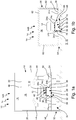
- Figures 1a and 1b 10 designates a treatment system for treating workpieces 12 with one or more treatment devices 14, wherein Figure 1a shows as a treatment device 14 a painting booth 14A, in which workpieces 12, which are exemplified as vehicle bodies, are coated with a paint to be applied.
- Figure 1b shows as the treatment device 14 a dryer 14B in which, for example, the applied lacquer is dried and which is explained further below.
- the painting booth 14 comprises a housing 16 which delimits a treatment room 18 and comprises side walls 20, a ceiling 22 and a treatment room floor 24.
- the treatment room 18 consequently defines a coating room.
- Figure 1a denotes 26 a carriage of a transport carriage 28, which is initially only shown schematically, and which is separated from the treatment room 18 by a protective barrier 30, by means of which contaminants and in particular overspray are prevented.
- a transport system designated as a whole by 32 comprises a large number of such transport carriages 28 on which the workpieces 12 are transported.
- the protective barrier 30 provides a travel space 34 for the respective undercarriage 26 of the transport vehicle 28 and thus defines a travel space housing 36 Only hold the spray booth 14A overspray and, unlike the dryer 14B described below, do not provide any thermal or other insulation, for example.
- the travel compartment housing 36 has a connecting passage 38 for a connecting device 40 of the transport carriage 28, which couples its undercarriage 26 to a fastening device 42, to which a workpiece 12 or a corresponding workpiece holder for workpieces 12 can be fastened.
- the connection passage 38 is only in the Figures 2 and 4th provided with a reference number.
- the connecting device 40 comprises at least one upwardly angled strut 40A, two such struts 40A being present for reasons of stability; each existing strut 40A couples the undercarriage 26 of the transport carriage 28 to the fastening device 42.
- the struts 40A can also be rectilinear.
- the undercarriage 26 of the transport carriage 28 moves in the travel space 34 and carries the fastening device 42 with it in the treatment room 18, the connecting device 40 extending through the connecting passage 38.
- the treatment device 14 and the transport system 32 are coordinated with one another such that only part of the transport system 32 moves in the treatment room 18, while the other part of the transport system 32 is moved outside the treatment room 18.
- the driving space 34 is thus arranged outside the treatment room 18 and, in the present exemplary embodiments, is separated upwards by a partition which can be designed as part of the treatment room floor 24.
- a partition which can be designed as part of the treatment room floor 24.
- this partition is a section 24a of the treatment room floor 24, the driving space 34 below this Section 24a of the treatment room floor 24 is arranged.
- the treatment room floor 24 has an angled course overall and has two sections 24b laterally next to the section 24a, which are offset downwards from the section 24a and at their edges facing the center of the treatment room 18 by an upwardly extending section 24c are connected to the opposite edges of section 24a.
- the sections 24c can deviate from Figure 1a also be straightforward.
- the travel space 34 overlaps the treatment room 18 in cross section.
- the partition wall can also be a side wall or the ceiling of the treatment room 18.
- the travel space housing 36 is preferably dimensioned such that the housing walls are at a distance of at most 40 cm from a component of the transport carriage 28 which projects most outward. It is more favorable if this distance is between 15 cm and 30 cm. This distance is particularly preferably between 1 cm and 15 cm.
- Known painting robots 44 are arranged in the treatment room 18 of the painting booth 14.
- the ceiling 22 of the painting booth 14 is designed in the usual way as the lower boundary of an air supply space 46 with a filter ceiling 48.
- the treatment room 18 is open at the bottom, for which purpose the treatment room floor 24 is formed in the sections 24b next to the driving compartment housing 36 as a flow-permeable grating 50 which can be walked on at least in some areas.
- Cabin air enters the treatment room 18 of the painting booth 14 from the air supply space 46 and takes up overspray on its flow path downwards before it flows over the permeable grating 50 into an area 52 below the treatment room 18.
- a separating device 54 In this area 52 there is a separating device 54, with the help of which entrained overspray is removed from the cabin air; The cleaned cabin air can then, if appropriate after a predetermined conditioning, be returned to the air supply space 46 in a circuit.
- a separating device 54 can, for example, comprise exchangeable filter units, be designed as an electrostatically operating separating device, or also combine these two filtering techniques; both variants are known per se and therefore do not need to be explained further. Other known filter techniques can also be implemented and combined.
- the treatment room 18 is delimited by a dryer housing 56, which comprises the treatment room floor 24 as a thermally insulating dryer floor 58 and also thermally insulating side walls 60 and a thermally insulating ceiling 62.
- the treatment room 18 thus defines a drying room in the dryer 14B.
- Both the painting booth 14A and the dryer 14B are operated continuously and consequently have an entrance at one end and an exit at the opposite end, which cannot be seen in the sections shown.
- the respective treatment room 18 is then designed as a coating tunnel or as a drying tunnel. If there are branching paths in the treatment room 18, the number of inputs can differ from the number of outputs. However, batch systems are also possible in which the treatment room has only a single access, via which the workpieces 12 are conveyed into the treatment room and out of the treatment room after the treatment.
- the dryer 14B and the transport system 32 are also coordinated with one another such that only part of the transport system 32 moves in the treatment room 18, while the other part of the transport system 32 is moved outside the treatment room 18.
- the statements made above regarding the painting booth 14a apply analogously to the construction of the driving space 34, the driving space housing 36, in contrast to the painting booth 14A, not only being designed as a protective barrier against contamination, but also being thermally insulating.
- the sections 24b of the treatment room floor 24 in the dryer 14B are also not designed as a grating, rather all sections 24a, 24b and 24c of the angled treatment room floor 24 are suitably thermally insulating and part of the dryer housing 56.
- Vertical support pillars 64 can be seen between the treatment room floor 24 and a plant floor, which essentially support the treatment room 18 on the plant or hall floor, which is not specifically designated.
- the travel space 34 overlaps in cross section in an upper region 66 with the treatment room 18. Furthermore, a lower region 68 is arranged at a height below the sections 24b of the treatment room floor 24.
- an arrangement can also be formed as in the painting booth 14B, in which the travel space 34 completely overlaps the treatment room 18 in cross section.
- the treatment room floor 24 can also be flat, then a corresponding section 24a of the treatment room floor 24 forms the partition between the treatment room 18 and the driving area 34, this section 24a then moving laterally Direction immediately and in the same horizontal plane merges into sections 24b without vertical sections 24c.
- the driving space 34 is then arranged completely at a level below the treatment room floor 24.
- the driving space 34 is defined by the driving space housing 36, i.e. limited at least in some areas.
- the passenger compartment housing 36 in each case comprises the vertical sections 24c of the treatment room floor 24 and its section 24a, i.e. the partition to the treatment room 18.
- the travel space housing 36 also comprises two further housing walls 70, 72, which extend downward in the lower region 68 in the longitudinal direction of the treatment room 18 and from the treatment room floor 24. These further housing walls 70, 72 form approximately a continuation of the vertical sections 24b of the treatment room floor downwards.
- the cabin housing 36 can also be a separate one Have housing bottom; such a separate floor is present in the painting booth 14A and in Figure 1a designated with 74. In the dryer 14B, a corresponding section of the plant floor takes over this task.
- the driver's compartment housing 36 is open on the end faces of the treatment device 14. If there is a modification, there could be locks; in any case, it must be possible for the transport carriages 28 to enter the driving space 34 at the entrance of the treatment device 14 and to be able to move out of the driving space 34 at the exit of the treatment device 14.
- the cabin housing 36 does not have to be designed to be flow-tight or fluid-tight, although this can be provided as a modification.
- the connecting passage 38 which connects the driving space 34 to the treatment room 18, is complementary to the connecting device 40 of the transport vehicle 28.
- the connecting passage 38 is designed in a straight line and as a straight-line through slot or gap which is formed extends between the entrance and the exit in the section 24a of the treatment room floor 24.
- the connecting passage 38 can, however, also be angled, that is to say in cross section, for example, be formed like a labyrinth.
- the connecting device 40 is then designed accordingly.
- the atmosphere contaminated with pollutants such as overspray or solvents can flow from the treatment room 18 into the driving space 34 and, on the other hand, atmosphere from the driving space 34, which can be contaminated, for example, with abrasion or lubricants from the transport system 32 in the driving space 34, into the Access treatment room 18.
- a shielding device 76 is also present. In the present exemplary embodiments, this comprises a scale seal 78.
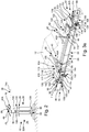
- FIG. 2 A rail-bound transport system 32A is now shown as the first exemplary embodiment of the transport system 32, whereas the Figures 4, 5a and 5b as a second embodiment illustrate a transport system 32B in which the Transport trolleys 28 are designed as free-moving transport trolleys in the sense of driverless transport systems which are known to the person skilled in the art as so-called AGVs and in which the transport trolleys 28 carry an environment sensor system 80 with them. Only in the Figures 3a and 5b all components and parts are provided with reference symbols.
- the fastening device 42 is matched to workpieces 12 in the form of vehicle bodies.
- the fastening device 42 comprises a support profile 82 with bearing bolts, which are not specifically identified and work together in a manner known per se and corresponding counter-elements on the vehicle body, so that the vehicle body 14 can be fixed to the fastening device 42.
- the fastening device 42 can also have a plurality of sets of such bearing bolts, which are adapted to different vehicle bodies with different dimensions and configurations, so that the fastening device 42 can be used flexibly for different vehicle body types.
- the fastening device 42 thus receives a vehicle body directly, without the vehicle body 14 being fastened to a workpiece carrier, such as a skid known per se.
- the rail-bound transport system 32A comprises a rail system 84 with a support rail 86 on which the transport carriages 28 can be moved and which has an I-shaped profile in a manner known per se and is anchored to the plant floor.
- the mounting rail 86 thus grounded is single-track; alternatively, the rail system 84 can also be designed as a multi-track system, in particular as a two-track system.
- the support rail 86 can also have a different profile.
- the undercarriage 26 runs on the mounting rail 86 and, in the present exemplary embodiment, comprises a precursor unit 88 leading in the transport direction and a trailing unit 90 lagging in the transport direction.
- the transport carriage 28 can be designed such that it is able to pass through curved sections of the mounting rail 86.
- the precursor unit 88 and the follower unit 90 be connected to one another in an articulated manner by a longitudinal strut 92 on swivel joints 94.
- the longitudinal strut 92 is then coupled to the connecting device 40.
- the transport carriage 28 can be set up in such a way that it can also overcome inclined sections, that is to say ascending or descending sections in the transport direction, of the support rail 86.
- the forerunner unit 88 and the forerunner unit 90 are largely identical in construction, individual components and components being positioned mirrored on a straight section of the mounting rail 86 with respect to a plane perpendicular to the transport direction.
- Corresponding parts and components of the precursor unit 88 and the trailing unit 90 have the same reference numerals.
- the components described below with reference to the precursor unit 88 are accordingly also encompassed by the follower unit 90, unless stated otherwise.
- the precursor unit 88 supports a drive roller 96 which rolls on a drive tread 98 of the mounting rail 86 and is driven by a drive motor 100 which is carried by the precursor unit 88.
- the drive running surface 98 of the mounting rail 86 is the surface on the upper side of the mounting rail 86 and accordingly also runs horizontally in horizontal sections of the mounting rail 86.
- the drive tread 98 can also run vertically, for example; In this case, the drive roller 96 presses laterally against the support rail 86 as a friction wheel.
- the transport carriages 28 each carry their own drive system 102, so that the transport carriages 28 can be driven and moved independently of one another.
- the own drive system 102 is formed by the drive rollers 96 and the associated drive motors 100.
- a chassis unit 104 of the precursor unit 88 supports a passive support roller 106 at a distance from the drive roller 96, which is also on the drive running surface 98 of the support rail 86 rolls off. Also stores the chassis unit 104 of the precursor unit 88 has a plurality of lateral guide rollers 108 which rest on both sides of the support rail 86 and thus prevent the precursor unit 88 from tilting to the side in a manner known per se.
- the precursor unit 88 further comprises a drive frame 110 which supports the drive roller 96 with the drive motor 100 and guide rollers 108 on both sides of the support rail 86.
- the drive frame 110 is connected in an articulated manner via a support crossbar 112 to a support frame 114, which in turn supports the support roller 106 and likewise guide rollers 108 on both sides of the support rail 86.
- the articulated connection of the drive frame 110 to the support frame 114 takes place via coupling joints which are not specifically provided with a reference number and which allow the support rail 86 to pass through curves.
- the transport carriage 28 carries with it an autonomous energy supply device 116 for the energy supply to the drive motors 100 of the precursor unit 88 and the follower unit 90.
- This is to be understood as an energy supply device which ensures the energy supply to the drive motors 100 while driving, that is to say during the movement of the transport carriage 28, independently of external energy sources.
- the energy supply device 116 is designed with rechargeable energy stores 118 with at least one energy storage unit 120.
- An energy storage unit 120 for the respective drive motor 100 is present on each chassis unit 104.
- a rechargeable energy storage unit 120 for electrical energy can be provided in the form of an accumulator or a capacitor. In the case of a modification that is not specifically shown, only a single energy storage unit 120 can be provided for both drive motors 100.
- compressed gas storage can also be provided as an energy source for compressed gas drives.
- the transport carriages 28 are supplied with energy in a manner known per se via a conductor rail on the mounting rail 86 and corresponding sliding contacts on the transport carriage 28.
- Such devices are generally to be understood as energy transmission elements of the drive system 102.
- Each transport carriage 28 now has atmosphere-sensitive components, which are generally designated 122 and whose operation can be impaired by one or more harmful parameters of a harmful atmosphere surrounding the atmospheric-sensitive component 122, in particular by the temperature or the composition of the surrounding harmful atmosphere.
- atmosphere-sensitive components which are generally designated 122 and whose operation can be impaired by one or more harmful parameters of a harmful atmosphere surrounding the atmospheric-sensitive component 122, in particular by the temperature or the composition of the surrounding harmful atmosphere.
- such atmosphere-sensitive components can react undesirably and negatively to an ambient atmosphere which deviates from a normal atmosphere and which defines a corresponding harmful atmosphere in such a case.
- a normal atmosphere can be understood to mean, for example, an atmosphere surrounding the treatment system 10, in particular room temperature air.
- a harmful atmosphere contains in particular particles that are ignitable, sticky and / or electrically conductive and / or a harmful atmosphere has a temperature of more than 40 ° C. Damage parameters thus define properties of the harmful atmosphere to which the atmosphere-sensitive components 122 of the transport car 28 react sensitively.
- the temperature can represent a first harmful parameter and the composition of the harmful atmosphere a second harmful parameter, with respect to the composition only a single compound that is present in the harmful atmosphere can also define a separate harmful parameter.
- the harmful atmosphere surrounding the atmosphere-sensitive component 122 is to be understood as meaning the atmosphere in a surrounding volume in which this atmosphere can undesirably influence the atmosphere-sensitive component 122. It can be harmless that in areas further away from the atmosphere-sensitive component (s) 122 the harmful atmosphere remains unchanged if this does not impair the atmosphere-sensitive components 122 and thus the operability of the transport vehicle 28.
- Atmosphere-sensitive components 122 of the transport vehicle 28 include, among other things, components of the undercarriage 26 as such, for example the precursor unit 88 and the follower unit 90 and there in particular articulated connections or the rotary bearings of existing rollers.
- electronic components in the case of the rail-bound transport wagons in particular the energy supply device 116 and its associated components, for example the energy store 118 and the energy supply unit 120, but also the above-mentioned energy transmission elements in the form of, for example, conductor lines and sliding contacts are atmosphere-sensitive components 122.
- Such a harmful atmosphere which is a burden for these components 122, can arise in the driving space 34 by, as mentioned above, the polluted atmosphere flowing out of the treatment room 18 through the connecting passage 38 into the driving space 34. Even with an existing shielding device 76, a harmful atmosphere builds up in the driving space 34 over time.
- the pollutants are formed in particular by overspray particles.
- the atmosphere in the treatment room 18 is enriched with solvent; these solvent components burden the conveyor technology.
- the atmosphere in the treatment room 18 is also hot, which is why the atmosphere in the driving room 34 can increase over time to a temperature at which the atmosphere-sensitive, in this case temperature-sensitive, components 122 can be damaged.
- the travel space 34 can also heat up without the atmosphere flowing out of the treatment room 18 through the connecting passage 38, since thermal energy can be transferred from the treatment room floor 24 to the travel space 34 via the section 24a of the treatment room floor 24 if the thermal insulation is too weak.
- the treatment device 14 can also be designed as a processing station, in which the workpieces 12 are ground off, for example, and corresponding grinding particles are formed. Such abrasive particles can also possibly get into the driving space 34 and damage or at least burden the atmosphere-sensitive components 122.
- a compensation system 126 by means of which at least one harmful parameter of the harmful atmosphere surrounding the atmosphere-sensitive component 122 can be compensated.
- Compensation of the harmful atmosphere is understood to mean that one or more measures which antagonize the harmful atmosphere are taken to at least, i.e. in any case, to change the harmful atmosphere surrounding the sensitive component 122 to an atmosphere that has less and at best no harmful effect on the atmosphere sensitive component 122.
- the considered damage parameter is changed with the aid of the compensation system 124 to a value at which the surrounding atmosphere places at least less stress on the atmosphere-sensitive component 122 than before the change of the damage parameter.
- the considered damage parameter is changed to a value which also defines the required operating conditions of the atmosphere-sensitive component 122, at which it works perfectly.
- the temperature is reduced accordingly to a lower value.
- the harmful parameter affects the composition of the surrounding atmosphere
- the composition of the surrounding component is changed. This can be done, for example, by an atmosphere exchange in the environment of the atmosphere-sensitive component. Dilution of harmful gaseous substances or those in the transition from liquid to gaseous substances to a concentration which is negligible for component 122 can also be carried out. Solid microparticles can be removed from a gas volume flow before they cause damage to the component 122 that impairs functionality. If necessary, targeted chemical measures can also be taken against a certain harmful component of the surrounding harmful atmosphere, for example, by spraying in suitable chemicals.
- the compensation system 124 can operate according to two alternative or complementary concepts.
- the transport carriage 28 carries a compensation device 126 with it, by means of which at least one harmful parameter of the surrounding harmful atmosphere can be compensated. This is further explained using the Figures 2, 3a , 3b , 4, 5a and 5b described.
- the transport carriage 28 is set up to cooperate with a compensation device 128 which is external to the transport carriage 28 and by means of which at least one harmful parameter of the surrounding harmful atmosphere can be compensated for.
- a compensation device 128 which is external to the transport carriage 28 and by means of which at least one harmful parameter of the surrounding harmful atmosphere can be compensated for.
- the term "external" is intended to clarify that this compensation device 128 is not carried by the transport carriage 28.
- such an external compensation device 128 can be assigned to the treatment system 10, in which the transport system 32 with the transport car 28 is used. This is related to the below Figures 6 , 7a and 7b explained.
- the compensation devices 126, 128 are designed as a cooling device 130 to compensate or render harmless, the harmful atmosphere already sufficient to lower the ambient temperature at the atmosphere-sensitive component (s) 122.
- the temperature can be reduced by exchanging the atmosphere or by exchanging heat.
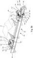
- the Figures 3a and 3b illustrate as a carried compensation device 126 a flow generating device 132, by means of which a material flow can be generated on the atmosphere-sensitive component 122, which compensates one or more harmful parameters.
- the material flow generated cools the atmosphere-sensitive component and / or displaces the surrounding harmful atmosphere.
- the material flow is a gas flow, which is preferably an air flow.
- the dolly 28 of Figure 3a now carries with it two flow generating devices 132, which in the exemplary embodiment shown are illustrated as ventilation devices 134 and in the exemplary embodiment shown are each arranged on one side of the chassis unit 104 of the precursor unit 88 and the trailing unit.
- the drive motors 100 are controlled and synchronized with the aid of the control device 140, the control device 140 communicating with a higher-level central control.
- the ventilation devices 134 which are designed here as radial fans, each have an air guide element 142, which leads to the control device 140 or the drive motor 100.
- the air guiding elements 142 are connected to the respective outlet of the ventilation devices 134.
- the air guiding elements 142 can be designed as rigid air guiding elements 144 or as flexible air guiding elements 146, with which it is fundamentally possible to guide an air flow generated by the ventilation device 134 around or past several components of the transport carriage 28 that are not to be cooled.
- an active cooling unit 148 is provided on the precursor unit 88, which supplies the ventilation device 134 with a cooled atmosphere via cooling guide elements 150.
- the exemplary embodiment shown comprises Peltier elements 152 arranged on the sensitive components 122.
- a cooling housing 154 is also provided which surrounds the sensitive components 122, here for example the energy store 118 and the control device 140, and accommodates or carries the Peltier elements 152. This arrangement reduces the temperature within the cooling housing 154.
- An exemplary embodiment in which the Peltier elements 134 are attached directly to the atmosphere-sensitive components 122 without a cooling housing 154 is not specifically shown.
- Such Peltier elements can, for example, also be included in the cooling unit 148 mentioned above.
- the energy supply for the compensation device 126 carried is carried out via the autonomous energy supply device 116, which is also carried by the transport carriage 28.
- an exemplary embodiment that is not specifically shown furthermore also includes a second energy supply device that is set up specifically for the compensation device 126 and which, independently of the first energy supply device 116, the compensation device 126 powered.
- the Figures 4, 5a and 5b once again illustrate carried compensation devices 126 using the example of the above-mentioned AGV transport system 32B.
- the transport trolleys 28 can travel on the plant floor or floor 74 of the travel space 34.
- the drive system 102 of the transport carriage 28 of the AGV transport system 32B is preferably omnidirectional, so that the transport carriage 28 can travel in any direction from a standing position.
- the omnidirectional drive system 102 comprises drive-turn modules 156 which are known per se.
- all-side wheels or mecanum wheels can also be present, as is known per se in the prior art.
- the travel-turn modules 156 include only in the Figures 7a and 7b Drive units 158 indicated by dashed lines, which are coupled to drive wheels 160 projecting downward in such a way that the drive wheels 160 are not only used to propel the transport vehicle 28 driven, but can also be rotated about a vertical axis of rotation.
- the environment sensor system 80 comprises sensors 162 attached to the front and rear of the undercarriage 26 of the transport vehicle 28. With this environment sensor system 80, obstacles in the travel path of the transport vehicle 28, be it other transport vehicles 28 or other objects appearing in the movement field of the transport vehicle 28, can be detected and sent to the above Central control are transmitted, which calculates an alternative route to the destination of the transport carriage 28 and forwards corresponding control commands to the transport carriage 28 via the control device 140 attached to the transport carriage 28.
- the sensors 162 also form an atmosphere-sensitive component 122.
- a data carrier can be present.
- a measuring device can be present in a transport carriage 28, by means of which the speed of the transport carriage 28 and / or the position of the transport carriage 28 along the treatment path and / or the weight of the at least one workpiece 14 and / or the Temperature of the environment of the trolley 28 can be detected.
- the data of such a measuring device can also be stored on the data carrier. All of these components can also be atmosphere sensitive components 122.
- the compensation device 126 carried along is according to the driverless transport carriage 28 Figure 5a again formed as a ventilation device 134 and according to the transport carriage 28 Figure 5b again equipped with Peltier elements 152.
- the transport carriage 28 comprises receptacles 164 in a side surface 166 or a top surface 168 of the Transport carriage 28, wherein in Figure 5b the cooling housing 154 is provided on the top surface 168.
- the compensation device 126 carried along can also comprise a heat exchanger device, a boiling cooling element, in particular a compression cooling element, instead of the embodiments explained.
- a gas storage device in particular a liquid or compressed gas storage device, can be provided, which defines the material source for the material flow that can be generated by means of the flow generating device 132.
- the Figures 6 , 7a and 7b the second concept of the compensation system 124 with the external compensation device 128, which is specifically identified here as a system part 170 of the dryer 14B. This concept is described in conjunction with the AGVS transport system 32B by way of example only.
- the external compensation device 128 also includes a flow generating device 132, which in this exemplary embodiment is designed as a ventilation device 172, which cooperates with a flow control system 174, which can be designed, for example, as a pipe system and through the lower region 68 under the treatment room floor 24 into the travel space 34 for the Transport system 32 protrudes .
- the flow control system 174 defines one or more delivery elements 176, which are arranged in the driving space 34 so that the transport carriage 28 can interact with it.
- a material flow that can compensate for one or more harmful parameters, in particular an air flow, can be directed from the dispensing elements 176 directly onto the one or more atmosphere-sensitive components 122.
- an opening 178 which is complementary to the delivery element 176 of the air guidance system 174, is provided on or at least in the vicinity of the sensitive component 122 of the transport carriage 28, which leads to an internal flow system 180 arranged in the transport carriage 28, which in turn leads to a flow path the existing atmosphere-sensitive components 122 provides.
- a delivery element 176 of the air-guiding system 174 can dip into the opening 178 on the transport carriage 28 as a type of connection piece, or can only be kept at a distance therefrom.
- the opening 178 thus provides, by way of example, a device by means of which the transport carriage 28 can be coupled to the external compensation device 128.
- the delivery element 176 of the air guidance system 174 is to dip into the opening 178 on the transport carriage 28, a relative movement between these components must be possible.
- the dispensing element 176 can be moved on the one hand, or on the other hand the opening 178 can be moved towards the dispensing element 176 as a kind of inlet funnel.
- an adjustment device 182 is also arranged in the flow control system 174, with which the volume flow can be adjusted continuously and can be designed, for example, as a pneumatic valve or as an adjustable ventilation grille. Alternatively, the volume flow can also be set by the speed and the associated delivery rate of the ventilation device 172.
- Figure 7a illustrates as a first variant the plant-based compensation of a harmful atmosphere of the atmosphere-sensitive components 122 in a clocked operating mode of the dryer 14B.
- the clocking operating mode it is possible to determine the standstill positions of the transport carriages 28 in advance for each processing step and thus to know them with sufficient accuracy. If the positions of the transport carriages 28 are known in successive treatment steps in a clocked production line, delivery elements 176 of the flow control system 174 can be arranged for the corresponding positions in such a way that they can cooperate with the transport carriages 28 when the transport carriages 28 come to a standstill.
- compensation device 126 is carried by the transport vehicle 28, compensation for one or more harmful parameters of the existing harmful atmosphere can be achieved.
- the delivery elements 176 of the flow control system 174 can also be present on both sides; The transport carriages 28 then have corresponding openings 178 on both sides
- the flow control system 174 comprises a longitudinal line 184, which runs along the drive direction of the transport carriage 28 in the travel space 34 and each has one or more delivery elements 176.
- the delivery elements 176 of the air guide system 174 can be immersed in the opening 178 of the transport car 28, the external compensation device 128, the air guide system 174 or only the delivery elements 176 of the external compensation device 128 are mounted so that they can be moved perpendicularly to the drive direction of the transport car 28 by means of a linear drive (not shown) .
- the air guide system 174 is additionally mounted so as to be able to compensate for fluctuations in the transport carriage positions by means of a further linear drive along the drive direction of the transport carriage 28.
- the exemplary embodiment shown is provided on the side of the longitudinal line 184 facing the center of the driving space 34, and also has a slot-shaped ventilation opening 186 running longitudinally to the drive direction, which has sealing elements 188, in this exemplary embodiment lamellar sealing elements, which largely seal the ventilation opening 186 in a closed position.
- each transport carriage 28 has release elements 190 at its opening 178, which generate a window 192 moving along the ventilation opening 186 in the sealing elements 188 of the longitudinal line 184 with a continuous movement of the transport carriage 28 .
- the opening 178 thus provides an alternative device by means of which the transport carriage 28 can be coupled to the external compensation device 128.
- the rail-bound transport system 32a explained above can also cooperate with an external compensation device 128. If a transport cart 28 does not have an internal flow system 180 with one or more access openings 178, existing delivery elements 176 of the flow control system 174 of the external compensation device 128 can be positioned such that the atmosphere-sensitive components 122 can be guided past the delivery elements 176 sufficiently close that the discharged ones Flow reached these components 122.
- the external compensation device 128 can also be designed in the variants with Peltier elements 152, heat exchangers, evaporative cooling elements or the like, which are then arranged in the longitudinal direction of the treatment device 14 in the driving space 34.
- the compensation device 126, 128 can be operated continuously or intermittently.
- the operation of the compensation device 126, 128 in a painting booth 14A can be interrupted if no coating is applied in the treatment room 18, since then no overspray can flow into the driving room 34 either.
- the compensation device 126, 128 can, for example, only be activated as a function of the temperature in the driving space 34, which is determined by the measuring device described above if the temperature exceeds a predetermined threshold value.
Landscapes
- Engineering & Computer Science (AREA)
- Mechanical Engineering (AREA)
- General Engineering & Computer Science (AREA)
- Manufacturing & Machinery (AREA)
- Chemical & Material Sciences (AREA)
- Combustion & Propulsion (AREA)
- Transportation (AREA)
- Automobile Manufacture Line, Endless Track Vehicle, Trailer (AREA)
- Coating Apparatus (AREA)
- Drying Of Solid Materials (AREA)
Priority Applications (1)
| Application Number | Priority Date | Filing Date | Title |
|---|---|---|---|
| HRP20240174TT HRP20240174T1 (hr) | 2018-09-21 | 2019-09-03 | Postrojenje za obradu i postupak za obradu radnih predmeta |
Applications Claiming Priority (1)
| Application Number | Priority Date | Filing Date | Title |
|---|---|---|---|
| DE102018123269.1A DE102018123269A1 (de) | 2018-09-21 | 2018-09-21 | Transportwagen zum Transportieren von Werkstücken, Behandlungsanlage und Verfahren zum Behandeln von Werkstücken |
Publications (3)
| Publication Number | Publication Date |
|---|---|
| EP3627084A2 true EP3627084A2 (fr) | 2020-03-25 |
| EP3627084A3 EP3627084A3 (fr) | 2020-08-26 |
| EP3627084B1 EP3627084B1 (fr) | 2023-11-08 |
Family
ID=67850962
Family Applications (1)
| Application Number | Title | Priority Date | Filing Date |
|---|---|---|---|
| EP19195205.0A Active EP3627084B1 (fr) | 2018-09-21 | 2019-09-03 | Installation de traitement et procédé de traitement des pièces |
Country Status (6)
| Country | Link |
|---|---|
| EP (1) | EP3627084B1 (fr) |
| DE (1) | DE102018123269A1 (fr) |
| ES (1) | ES2970750T3 (fr) |
| HR (1) | HRP20240174T1 (fr) |
| HU (1) | HUE064942T2 (fr) |
| PL (1) | PL3627084T3 (fr) |
Families Citing this family (1)
| Publication number | Priority date | Publication date | Assignee | Title |
|---|---|---|---|---|
| DE102021132996A1 (de) | 2021-12-14 | 2023-06-15 | Bayerische Motoren Werke Aktiengesellschaft | Verfahren zur Erhebung von Produktionsdaten durch ein fahrerloses Transportfahrzeug |
Family Cites Families (10)
| Publication number | Priority date | Publication date | Assignee | Title |
|---|---|---|---|---|
| EP0314820B1 (fr) * | 1987-11-02 | 1992-04-01 | Vogel & Noot Industrieanlagenbau Gesellschaft m.b.H. | Dispositif de refroidissement de l'espace sous les voitures dans un four tunnel |
| DE19710045A1 (de) * | 1997-03-12 | 1998-09-17 | Haesler Andreas Dipl Ing Fh | Brennwagenaufbau |
| US7044346B2 (en) * | 2003-06-02 | 2006-05-16 | Gulf Stream Coach, Inc. | Roof rack for recreational vehicle |
| DE102007003683B4 (de) * | 2007-01-25 | 2008-11-13 | Häßler, Andreas, Ing.(grad.) | Herd-Vorrichtung für einen Durchlaufofen |
| DE102011110986B4 (de) * | 2011-08-18 | 2013-03-14 | Eisenmann Ag | Verfahren und Anlage zur Behandlung von Gegenständen |
| DE102015006098A1 (de) * | 2015-05-09 | 2016-11-10 | Eisenmann Se | Temperiervorrichtung zum Temperieren von Werkstücken |
| DE102016004484A1 (de) * | 2016-04-13 | 2017-10-19 | Eisenmann Se | Verfahren und Fertigungsanlage zur Herstellung von Fahrzeugen und Oberflächenbehandlungsanlage zur Oberflächenbehandlung von Fahrzeugkarosserien |
| DE102016112324A1 (de) * | 2016-07-05 | 2018-01-11 | Eisenmann Se | Transportsystem |
| DE202017106843U1 (de) * | 2017-11-03 | 2017-11-17 | Dürr Systems Ag | Behandlungsanlage |
| DE202018100210U1 (de) * | 2018-01-15 | 2018-03-06 | Eisenmann Se | Behandlungsanlage zum Behandeln von Werkstücken |
-
2018
- 2018-09-21 DE DE102018123269.1A patent/DE102018123269A1/de not_active Withdrawn
-
2019
- 2019-09-03 EP EP19195205.0A patent/EP3627084B1/fr active Active
- 2019-09-03 ES ES19195205T patent/ES2970750T3/es active Active
- 2019-09-03 HR HRP20240174TT patent/HRP20240174T1/hr unknown
- 2019-09-03 PL PL19195205.0T patent/PL3627084T3/pl unknown
- 2019-09-03 HU HUE19195205A patent/HUE064942T2/hu unknown
Also Published As
| Publication number | Publication date |
|---|---|
| PL3627084T3 (pl) | 2024-04-02 |
| EP3627084A3 (fr) | 2020-08-26 |
| EP3627084B1 (fr) | 2023-11-08 |
| HRP20240174T1 (hr) | 2024-04-12 |
| ES2970750T3 (es) | 2024-05-30 |
| HUE064942T2 (hu) | 2024-04-28 |
| DE102018123269A1 (de) | 2020-03-26 |
Similar Documents
| Publication | Publication Date | Title |
|---|---|---|
| EP3442717B1 (fr) | Procédé et installation de fabrication pour la fabrication de véhicules et installation de traitement de surface pour le traitement de surface de carrosseries de véhicule | |
| EP3704001A1 (fr) | Procédé et installation de production de véhicules et installation de traitement de surface de carrosseries de véhicule | |
| DE69115831T2 (de) | Verbesserungen für Pulverbeschichtungskabinen mit geregelter Lüftung zur Beschichtung von Kraftfahrzeugen | |
| EP3712090A1 (fr) | Installation de traitement et procédé de traitement des pièces | |
| EP3852938B1 (fr) | Installation de traitement de surface et procédé permettant le traitement de surface de carrosseries de véhicule | |
| WO2016180516A1 (fr) | Dispositif de mise à température de pièces | |
| DE102006032804A1 (de) | Lackieranlage und zugehöriges Betriebsverfahren | |
| EP3511212B1 (fr) | Appareil de traitement et procédé de traitement de pièces | |
| EP3526534B1 (fr) | Appareil pour réguler la température, installation de traitement de surfaces, installation de production et méthode de production | |
| WO2012016637A1 (fr) | Dispositif de traitement de surface d'objets | |
| EP2433076A2 (fr) | Procédé et installation permettant de déposer un revêtement sur une pièce | |
| EP2427279B1 (fr) | Installation de lavage de pièces de carrosserie de véhicule à moteur et procédé de fonctionnement | |
| WO2021063443A1 (fr) | Système de traitement et procédé de traitement | |
| DE102018100719A1 (de) | Behandlungsanlage und Verfahren zum Behandeln von Werkstücken | |
| EP3627084B1 (fr) | Installation de traitement et procédé de traitement des pièces | |
| WO2018011389A1 (fr) | Dispositif, système et procédé servant à réguler la température de pièces | |
| EP3990997A1 (fr) | Chariot de transport autonome et système d'acheminement pour l'acheminement ainsi qu'installation de traitement pour le traitement de pièces à usiner | |
| EP3446953B1 (fr) | Dispositif de transport permettant de transporter des pièces à usiner dans une installation de traitement de surface | |
| EP3733489B1 (fr) | Installation d'usinage destinée à l'usinage de pièces | |
| WO2021175851A1 (fr) | Installation de traitement et procédé de traitement pour traiter des pièces | |
| DE102019131307A1 (de) | Förderanlage zum Fördern von Werkstücken, Fertigungsanlage mit einer solchen Förderanlage und Verfahren zum Fertigen von Werkstücken | |
| DE102017110926A1 (de) | Vorrichtung und Verfahren zum Temperieren von Werkstücken, insbesondere von Fahrzeugkarosserien | |
| DE202017007275U1 (de) | Oberflächenbehandlungsanlage zur Oberflächenbehandlung von Fahrzeugkarosserien und Fertigungsanlage zur Herstellung von Fahrzeugen | |
| DE102020103321A1 (de) | Verfahren und Vorrichtung zum Temperieren von Werkstücken, insbesondere von Fahrzeugkarosserien | |
| DE102023107439A1 (de) | Mobiler Roboter in einer Behälterbehandlungsanlage |
Legal Events
| Date | Code | Title | Description |
|---|---|---|---|
| REG | Reference to a national code |
Ref country code: HR Ref legal event code: TUEP Ref document number: P20240174T Country of ref document: HR |
|
| PUAI | Public reference made under article 153(3) epc to a published international application that has entered the european phase |
Free format text: ORIGINAL CODE: 0009012 |
|
| STAA | Information on the status of an ep patent application or granted ep patent |
Free format text: STATUS: THE APPLICATION HAS BEEN PUBLISHED |
|
| AK | Designated contracting states |
Kind code of ref document: A2 Designated state(s): AL AT BE BG CH CY CZ DE DK EE ES FI FR GB GR HR HU IE IS IT LI LT LU LV MC MK MT NL NO PL PT RO RS SE SI SK SM TR |
|
| AX | Request for extension of the european patent |
Extension state: BA ME |
|
| PUAL | Search report despatched |
Free format text: ORIGINAL CODE: 0009013 |
|
| AK | Designated contracting states |
Kind code of ref document: A3 Designated state(s): AL AT BE BG CH CY CZ DE DK EE ES FI FR GB GR HR HU IE IS IT LI LT LU LV MC MK MT NL NO PL PT RO RS SE SI SK SM TR |
|
| AX | Request for extension of the european patent |
Extension state: BA ME |
|
| RIC1 | Information provided on ipc code assigned before grant |
Ipc: F27D 9/00 20060101ALI20200718BHEP Ipc: F27B 9/26 20060101ALI20200718BHEP Ipc: B62D 65/18 20060101ALI20200718BHEP Ipc: F26B 15/16 20060101AFI20200718BHEP |
|
| STAA | Information on the status of an ep patent application or granted ep patent |
Free format text: STATUS: REQUEST FOR EXAMINATION WAS MADE |
|
| 17P | Request for examination filed |
Effective date: 20210224 |
|
| RBV | Designated contracting states (corrected) |
Designated state(s): AL AT BE BG CH CY CZ DE DK EE ES FI FR GB GR HR HU IE IS IT LI LT LU LV MC MK MT NL NO PL PT RO RS SE SI SK SM TR |
|
| STAA | Information on the status of an ep patent application or granted ep patent |
Free format text: STATUS: EXAMINATION IS IN PROGRESS |
|
| 17Q | First examination report despatched |
Effective date: 20210713 |
|
| RAP1 | Party data changed (applicant data changed or rights of an application transferred) |
Owner name: EISENMANN GMBH |
|
| GRAJ | Information related to disapproval of communication of intention to grant by the applicant or resumption of examination proceedings by the epo deleted |
Free format text: ORIGINAL CODE: EPIDOSDIGR1 |
|
| STAA | Information on the status of an ep patent application or granted ep patent |
Free format text: STATUS: GRANT OF PATENT IS INTENDED |
|
| GRAP | Despatch of communication of intention to grant a patent |
Free format text: ORIGINAL CODE: EPIDOSNIGR1 |
|
| INTG | Intention to grant announced |
Effective date: 20230613 |
|
| GRAS | Grant fee paid |
Free format text: ORIGINAL CODE: EPIDOSNIGR3 |
|
| GRAA | (expected) grant |
Free format text: ORIGINAL CODE: 0009210 |
|
| STAA | Information on the status of an ep patent application or granted ep patent |
Free format text: STATUS: THE PATENT HAS BEEN GRANTED |
|
| AK | Designated contracting states |
Kind code of ref document: B1 Designated state(s): AL AT BE BG CH CY CZ DE DK EE ES FI FR GB GR HR HU IE IS IT LI LT LU LV MC MK MT NL NO PL PT RO RS SE SI SK SM TR |
|
| REG | Reference to a national code |
Ref country code: GB Ref legal event code: FG4D Free format text: NOT ENGLISH |
|
| P01 | Opt-out of the competence of the unified patent court (upc) registered |
Effective date: 20231009 |
|
| REG | Reference to a national code |
Ref country code: CH Ref legal event code: EP |
|
| REG | Reference to a national code |
Ref country code: DE Ref legal event code: R096 Ref document number: 502019009857 Country of ref document: DE |
|
| REG | Reference to a national code |
Ref country code: IE Ref legal event code: FG4D Free format text: LANGUAGE OF EP DOCUMENT: GERMAN |
|
| REG | Reference to a national code |
Ref country code: LT Ref legal event code: MG9D |
|
| REG | Reference to a national code |
Ref country code: NL Ref legal event code: MP Effective date: 20231108 |
|
| PG25 | Lapsed in a contracting state [announced via postgrant information from national office to epo] |
Ref country code: GR Free format text: LAPSE BECAUSE OF FAILURE TO SUBMIT A TRANSLATION OF THE DESCRIPTION OR TO PAY THE FEE WITHIN THE PRESCRIBED TIME-LIMIT Effective date: 20240209 |
|
| PG25 | Lapsed in a contracting state [announced via postgrant information from national office to epo] |
Ref country code: IS Free format text: LAPSE BECAUSE OF FAILURE TO SUBMIT A TRANSLATION OF THE DESCRIPTION OR TO PAY THE FEE WITHIN THE PRESCRIBED TIME-LIMIT Effective date: 20240308 |
|
| REG | Reference to a national code |
Ref country code: HR Ref legal event code: T1PR Ref document number: P20240174 Country of ref document: HR |
|
| PG25 | Lapsed in a contracting state [announced via postgrant information from national office to epo] |
Ref country code: LT Free format text: LAPSE BECAUSE OF FAILURE TO SUBMIT A TRANSLATION OF THE DESCRIPTION OR TO PAY THE FEE WITHIN THE PRESCRIBED TIME-LIMIT Effective date: 20231108 |
|
| PG25 | Lapsed in a contracting state [announced via postgrant information from national office to epo] |
Ref country code: NL Free format text: LAPSE BECAUSE OF FAILURE TO SUBMIT A TRANSLATION OF THE DESCRIPTION OR TO PAY THE FEE WITHIN THE PRESCRIBED TIME-LIMIT Effective date: 20231108 |
|
| REG | Reference to a national code |
Ref country code: HU Ref legal event code: AG4A Ref document number: E064942 Country of ref document: HU |
|
| PG25 | Lapsed in a contracting state [announced via postgrant information from national office to epo] |
Ref country code: NL Free format text: LAPSE BECAUSE OF FAILURE TO SUBMIT A TRANSLATION OF THE DESCRIPTION OR TO PAY THE FEE WITHIN THE PRESCRIBED TIME-LIMIT Effective date: 20231108 Ref country code: LT Free format text: LAPSE BECAUSE OF FAILURE TO SUBMIT A TRANSLATION OF THE DESCRIPTION OR TO PAY THE FEE WITHIN THE PRESCRIBED TIME-LIMIT Effective date: 20231108 Ref country code: IS Free format text: LAPSE BECAUSE OF FAILURE TO SUBMIT A TRANSLATION OF THE DESCRIPTION OR TO PAY THE FEE WITHIN THE PRESCRIBED TIME-LIMIT Effective date: 20240308 Ref country code: GR Free format text: LAPSE BECAUSE OF FAILURE TO SUBMIT A TRANSLATION OF THE DESCRIPTION OR TO PAY THE FEE WITHIN THE PRESCRIBED TIME-LIMIT Effective date: 20240209 Ref country code: BG Free format text: LAPSE BECAUSE OF FAILURE TO SUBMIT A TRANSLATION OF THE DESCRIPTION OR TO PAY THE FEE WITHIN THE PRESCRIBED TIME-LIMIT Effective date: 20240208 Ref country code: PT Free format text: LAPSE BECAUSE OF FAILURE TO SUBMIT A TRANSLATION OF THE DESCRIPTION OR TO PAY THE FEE WITHIN THE PRESCRIBED TIME-LIMIT Effective date: 20240308 |
|
| REG | Reference to a national code |
Ref country code: ES Ref legal event code: FG2A Ref document number: 2970750 Country of ref document: ES Kind code of ref document: T3 Effective date: 20240530 |
|
| PG25 | Lapsed in a contracting state [announced via postgrant information from national office to epo] |
Ref country code: SE Free format text: LAPSE BECAUSE OF FAILURE TO SUBMIT A TRANSLATION OF THE DESCRIPTION OR TO PAY THE FEE WITHIN THE PRESCRIBED TIME-LIMIT Effective date: 20231108 Ref country code: RS Free format text: LAPSE BECAUSE OF FAILURE TO SUBMIT A TRANSLATION OF THE DESCRIPTION OR TO PAY THE FEE WITHIN THE PRESCRIBED TIME-LIMIT Effective date: 20231108 Ref country code: NO Free format text: LAPSE BECAUSE OF FAILURE TO SUBMIT A TRANSLATION OF THE DESCRIPTION OR TO PAY THE FEE WITHIN THE PRESCRIBED TIME-LIMIT Effective date: 20240208 Ref country code: LV Free format text: LAPSE BECAUSE OF FAILURE TO SUBMIT A TRANSLATION OF THE DESCRIPTION OR TO PAY THE FEE WITHIN THE PRESCRIBED TIME-LIMIT Effective date: 20231108 |
|
| PG25 | Lapsed in a contracting state [announced via postgrant information from national office to epo] |
Ref country code: DK Free format text: LAPSE BECAUSE OF FAILURE TO SUBMIT A TRANSLATION OF THE DESCRIPTION OR TO PAY THE FEE WITHIN THE PRESCRIBED TIME-LIMIT Effective date: 20231108 |
|
| PG25 | Lapsed in a contracting state [announced via postgrant information from national office to epo] |
Ref country code: SK Free format text: LAPSE BECAUSE OF FAILURE TO SUBMIT A TRANSLATION OF THE DESCRIPTION OR TO PAY THE FEE WITHIN THE PRESCRIBED TIME-LIMIT Effective date: 20231108 |
|
| PG25 | Lapsed in a contracting state [announced via postgrant information from national office to epo] |
Ref country code: SM Free format text: LAPSE BECAUSE OF FAILURE TO SUBMIT A TRANSLATION OF THE DESCRIPTION OR TO PAY THE FEE WITHIN THE PRESCRIBED TIME-LIMIT Effective date: 20231108 Ref country code: SK Free format text: LAPSE BECAUSE OF FAILURE TO SUBMIT A TRANSLATION OF THE DESCRIPTION OR TO PAY THE FEE WITHIN THE PRESCRIBED TIME-LIMIT Effective date: 20231108 Ref country code: RO Free format text: LAPSE BECAUSE OF FAILURE TO SUBMIT A TRANSLATION OF THE DESCRIPTION OR TO PAY THE FEE WITHIN THE PRESCRIBED TIME-LIMIT Effective date: 20231108 Ref country code: EE Free format text: LAPSE BECAUSE OF FAILURE TO SUBMIT A TRANSLATION OF THE DESCRIPTION OR TO PAY THE FEE WITHIN THE PRESCRIBED TIME-LIMIT Effective date: 20231108 Ref country code: DK Free format text: LAPSE BECAUSE OF FAILURE TO SUBMIT A TRANSLATION OF THE DESCRIPTION OR TO PAY THE FEE WITHIN THE PRESCRIBED TIME-LIMIT Effective date: 20231108 |
|
| REG | Reference to a national code |
Ref country code: DE Ref legal event code: R097 Ref document number: 502019009857 Country of ref document: DE |
|
| PLBE | No opposition filed within time limit |
Free format text: ORIGINAL CODE: 0009261 |
|
| STAA | Information on the status of an ep patent application or granted ep patent |
Free format text: STATUS: NO OPPOSITION FILED WITHIN TIME LIMIT |
|
| REG | Reference to a national code |
Ref country code: HR Ref legal event code: ODRP Ref document number: P20240174 Country of ref document: HR Payment date: 20240830 Year of fee payment: 6 |
|
| 26N | No opposition filed |
Effective date: 20240809 |
|
| PG25 | Lapsed in a contracting state [announced via postgrant information from national office to epo] |
Ref country code: SI Free format text: LAPSE BECAUSE OF FAILURE TO SUBMIT A TRANSLATION OF THE DESCRIPTION OR TO PAY THE FEE WITHIN THE PRESCRIBED TIME-LIMIT Effective date: 20231108 |
|
| PG25 | Lapsed in a contracting state [announced via postgrant information from national office to epo] |
Ref country code: SI Free format text: LAPSE BECAUSE OF FAILURE TO SUBMIT A TRANSLATION OF THE DESCRIPTION OR TO PAY THE FEE WITHIN THE PRESCRIBED TIME-LIMIT Effective date: 20231108 |
|
| PG25 | Lapsed in a contracting state [announced via postgrant information from national office to epo] |
Ref country code: MC Free format text: LAPSE BECAUSE OF FAILURE TO SUBMIT A TRANSLATION OF THE DESCRIPTION OR TO PAY THE FEE WITHIN THE PRESCRIBED TIME-LIMIT Effective date: 20231108 |
|
| REG | Reference to a national code |
Ref country code: CH Ref legal event code: PL |
|
| PG25 | Lapsed in a contracting state [announced via postgrant information from national office to epo] |
Ref country code: LU Free format text: LAPSE BECAUSE OF NON-PAYMENT OF DUE FEES Effective date: 20240903 |
|
| REG | Reference to a national code |
Ref country code: BE Ref legal event code: MM Effective date: 20240930 |
|
| PG25 | Lapsed in a contracting state [announced via postgrant information from national office to epo] |
Ref country code: BE Free format text: LAPSE BECAUSE OF NON-PAYMENT OF DUE FEES Effective date: 20240930 |
|
| PG25 | Lapsed in a contracting state [announced via postgrant information from national office to epo] |
Ref country code: CH Free format text: LAPSE BECAUSE OF NON-PAYMENT OF DUE FEES Effective date: 20240930 |
|
| PG25 | Lapsed in a contracting state [announced via postgrant information from national office to epo] |
Ref country code: IE Free format text: LAPSE BECAUSE OF NON-PAYMENT OF DUE FEES Effective date: 20240903 |
|
| REG | Reference to a national code |
Ref country code: HR Ref legal event code: ODRP Ref document number: P20240174 Country of ref document: HR Payment date: 20250826 Year of fee payment: 7 |
|
| PG25 | Lapsed in a contracting state [announced via postgrant information from national office to epo] |
Ref country code: FI Free format text: LAPSE BECAUSE OF FAILURE TO SUBMIT A TRANSLATION OF THE DESCRIPTION OR TO PAY THE FEE WITHIN THE PRESCRIBED TIME-LIMIT Effective date: 20231108 |
|
| PGFP | Annual fee paid to national office [announced via postgrant information from national office to epo] |
Ref country code: DE Payment date: 20250917 Year of fee payment: 7 |
|
| PGFP | Annual fee paid to national office [announced via postgrant information from national office to epo] |
Ref country code: PL Payment date: 20250812 Year of fee payment: 7 |
|
| PGFP | Annual fee paid to national office [announced via postgrant information from national office to epo] |
Ref country code: HU Payment date: 20250827 Year of fee payment: 7 Ref country code: GB Payment date: 20250923 Year of fee payment: 7 |
|
| PGFP | Annual fee paid to national office [announced via postgrant information from national office to epo] |
Ref country code: HR Payment date: 20250826 Year of fee payment: 7 |
|
| PGFP | Annual fee paid to national office [announced via postgrant information from national office to epo] |
Ref country code: FR Payment date: 20250922 Year of fee payment: 7 Ref country code: AT Payment date: 20250918 Year of fee payment: 7 |
|
| PGFP | Annual fee paid to national office [announced via postgrant information from national office to epo] |
Ref country code: CZ Payment date: 20250821 Year of fee payment: 7 |
|
| PGFP | Annual fee paid to national office [announced via postgrant information from national office to epo] |
Ref country code: IT Payment date: 20250930 Year of fee payment: 7 |
|
| PG25 | Lapsed in a contracting state [announced via postgrant information from national office to epo] |
Ref country code: CY Free format text: LAPSE BECAUSE OF FAILURE TO SUBMIT A TRANSLATION OF THE DESCRIPTION OR TO PAY THE FEE WITHIN THE PRESCRIBED TIME-LIMIT; INVALID AB INITIO Effective date: 20190903 |
|
| PGFP | Annual fee paid to national office [announced via postgrant information from national office to epo] |
Ref country code: ES Payment date: 20251020 Year of fee payment: 7 |