EP3627146A1 - Röntgenspektrometer - Google Patents
Röntgenspektrometer Download PDFInfo
- Publication number
- EP3627146A1 EP3627146A1 EP17909827.2A EP17909827A EP3627146A1 EP 3627146 A1 EP3627146 A1 EP 3627146A1 EP 17909827 A EP17909827 A EP 17909827A EP 3627146 A1 EP3627146 A1 EP 3627146A1
- Authority
- EP
- European Patent Office
- Prior art keywords
- slit
- ray
- rays
- irradiation area
- linear sensor
- Prior art date
- Legal status (The legal status is an assumption and is not a legal conclusion. Google has not performed a legal analysis and makes no representation as to the accuracy of the status listed.)
- Withdrawn
Links
- 230000007246 mechanism Effects 0.000 claims abstract description 69
- 238000001514 detection method Methods 0.000 claims abstract description 39
- 230000005284 excitation Effects 0.000 claims abstract description 32
- 230000008859 change Effects 0.000 claims abstract description 11
- 239000013078 crystal Substances 0.000 description 110
- 238000005259 measurement Methods 0.000 description 67
- 230000003287 optical effect Effects 0.000 description 20
- 238000004458 analytical method Methods 0.000 description 10
- 230000035945 sensitivity Effects 0.000 description 9
- 239000000203 mixture Substances 0.000 description 8
- 239000011572 manganese Substances 0.000 description 7
- 229910052748 manganese Inorganic materials 0.000 description 6
- 238000012986 modification Methods 0.000 description 6
- 230000004048 modification Effects 0.000 description 6
- 238000010586 diagram Methods 0.000 description 5
- 239000007788 liquid Substances 0.000 description 5
- 229910052688 Gadolinium Inorganic materials 0.000 description 4
- 238000013461 design Methods 0.000 description 4
- 239000006185 dispersion Substances 0.000 description 4
- 239000000843 powder Substances 0.000 description 4
- 229910052804 chromium Inorganic materials 0.000 description 3
- 238000010894 electron beam technology Methods 0.000 description 3
- 238000000921 elemental analysis Methods 0.000 description 3
- 229910052742 iron Inorganic materials 0.000 description 3
- 230000001678 irradiating effect Effects 0.000 description 3
- 238000000034 method Methods 0.000 description 3
- 239000011573 trace mineral Substances 0.000 description 3
- 235000013619 trace mineral Nutrition 0.000 description 3
- 229910052693 Europium Inorganic materials 0.000 description 2
- PWHULOQIROXLJO-UHFFFAOYSA-N Manganese Chemical compound [Mn] PWHULOQIROXLJO-UHFFFAOYSA-N 0.000 description 2
- 238000002441 X-ray diffraction Methods 0.000 description 2
- 238000013459 approach Methods 0.000 description 2
- 229910052785 arsenic Inorganic materials 0.000 description 2
- 229910052793 cadmium Inorganic materials 0.000 description 2
- 239000000470 constituent Substances 0.000 description 2
- 229910052802 copper Inorganic materials 0.000 description 2
- 229910052737 gold Inorganic materials 0.000 description 2
- 229910052738 indium Inorganic materials 0.000 description 2
- 229910052759 nickel Inorganic materials 0.000 description 2
- 238000005192 partition Methods 0.000 description 2
- 229910052697 platinum Inorganic materials 0.000 description 2
- 238000011160 research Methods 0.000 description 2
- 230000003595 spectral effect Effects 0.000 description 2
- 238000001228 spectrum Methods 0.000 description 2
- 229910052718 tin Inorganic materials 0.000 description 2
- 229910052720 vanadium Inorganic materials 0.000 description 2
- 229910052726 zirconium Inorganic materials 0.000 description 2
- XUIMIQQOPSSXEZ-UHFFFAOYSA-N Silicon Chemical compound [Si] XUIMIQQOPSSXEZ-UHFFFAOYSA-N 0.000 description 1
- 238000004998 X ray absorption near edge structure spectroscopy Methods 0.000 description 1
- 238000012512 characterization method Methods 0.000 description 1
- 230000000052 comparative effect Effects 0.000 description 1
- 150000001875 compounds Chemical class 0.000 description 1
- 230000000694 effects Effects 0.000 description 1
- 230000010354 integration Effects 0.000 description 1
- 230000000243 photosynthetic effect Effects 0.000 description 1
- 230000009467 reduction Effects 0.000 description 1
- 238000000980 resonant inelastic X-ray scattering Methods 0.000 description 1
- 230000004044 response Effects 0.000 description 1
- 238000010206 sensitivity analysis Methods 0.000 description 1
- 229910052710 silicon Inorganic materials 0.000 description 1
- 239000010703 silicon Substances 0.000 description 1
- 239000007787 solid Substances 0.000 description 1
- 239000000126 substance Substances 0.000 description 1
- 238000004876 x-ray fluorescence Methods 0.000 description 1
Images




Classifications
-
- G—PHYSICS
- G01—MEASURING; TESTING
- G01N—INVESTIGATING OR ANALYSING MATERIALS BY DETERMINING THEIR CHEMICAL OR PHYSICAL PROPERTIES
- G01N23/00—Investigating or analysing materials by the use of wave or particle radiation, e.g. X-rays or neutrons, not covered by groups G01N3/00 – G01N17/00, G01N21/00 or G01N22/00
- G01N23/22—Investigating or analysing materials by the use of wave or particle radiation, e.g. X-rays or neutrons, not covered by groups G01N3/00 – G01N17/00, G01N21/00 or G01N22/00 by measuring secondary emission from the material
- G01N23/225—Investigating or analysing materials by the use of wave or particle radiation, e.g. X-rays or neutrons, not covered by groups G01N3/00 – G01N17/00, G01N21/00 or G01N22/00 by measuring secondary emission from the material using electron or ion
-
- G—PHYSICS
- G01—MEASURING; TESTING
- G01N—INVESTIGATING OR ANALYSING MATERIALS BY DETERMINING THEIR CHEMICAL OR PHYSICAL PROPERTIES
- G01N23/00—Investigating or analysing materials by the use of wave or particle radiation, e.g. X-rays or neutrons, not covered by groups G01N3/00 – G01N17/00, G01N21/00 or G01N22/00
- G01N23/20—Investigating or analysing materials by the use of wave or particle radiation, e.g. X-rays or neutrons, not covered by groups G01N3/00 – G01N17/00, G01N21/00 or G01N22/00 by using diffraction of the radiation by the materials, e.g. for investigating crystal structure; by using scattering of the radiation by the materials, e.g. for investigating non-crystalline materials; by using reflection of the radiation by the materials
- G01N23/207—Diffractometry using detectors, e.g. using a probe in a central position and one or more displaceable detectors in circumferential positions
- G01N23/2076—Diffractometry using detectors, e.g. using a probe in a central position and one or more displaceable detectors in circumferential positions for spectrometry, i.e. using an analysing crystal, e.g. for measuring X-ray fluorescence spectrum of a sample with wavelength-dispersion, i.e. WDXFS
-
- G—PHYSICS
- G01—MEASURING; TESTING
- G01N—INVESTIGATING OR ANALYSING MATERIALS BY DETERMINING THEIR CHEMICAL OR PHYSICAL PROPERTIES
- G01N23/00—Investigating or analysing materials by the use of wave or particle radiation, e.g. X-rays or neutrons, not covered by groups G01N3/00 – G01N17/00, G01N21/00 or G01N22/00
- G01N23/22—Investigating or analysing materials by the use of wave or particle radiation, e.g. X-rays or neutrons, not covered by groups G01N3/00 – G01N17/00, G01N21/00 or G01N22/00 by measuring secondary emission from the material
-
- G—PHYSICS
- G01—MEASURING; TESTING
- G01N—INVESTIGATING OR ANALYSING MATERIALS BY DETERMINING THEIR CHEMICAL OR PHYSICAL PROPERTIES
- G01N23/00—Investigating or analysing materials by the use of wave or particle radiation, e.g. X-rays or neutrons, not covered by groups G01N3/00 – G01N17/00, G01N21/00 or G01N22/00
- G01N23/20—Investigating or analysing materials by the use of wave or particle radiation, e.g. X-rays or neutrons, not covered by groups G01N3/00 – G01N17/00, G01N21/00 or G01N22/00 by using diffraction of the radiation by the materials, e.g. for investigating crystal structure; by using scattering of the radiation by the materials, e.g. for investigating non-crystalline materials; by using reflection of the radiation by the materials
- G01N23/207—Diffractometry using detectors, e.g. using a probe in a central position and one or more displaceable detectors in circumferential positions
-
- G—PHYSICS
- G01—MEASURING; TESTING
- G01N—INVESTIGATING OR ANALYSING MATERIALS BY DETERMINING THEIR CHEMICAL OR PHYSICAL PROPERTIES
- G01N23/00—Investigating or analysing materials by the use of wave or particle radiation, e.g. X-rays or neutrons, not covered by groups G01N3/00 – G01N17/00, G01N21/00 or G01N22/00
- G01N23/22—Investigating or analysing materials by the use of wave or particle radiation, e.g. X-rays or neutrons, not covered by groups G01N3/00 – G01N17/00, G01N21/00 or G01N22/00 by measuring secondary emission from the material
- G01N23/223—Investigating or analysing materials by the use of wave or particle radiation, e.g. X-rays or neutrons, not covered by groups G01N3/00 – G01N17/00, G01N21/00 or G01N22/00 by measuring secondary emission from the material by irradiating the sample with X-rays or gamma-rays and by measuring X-ray fluorescence
-
- G—PHYSICS
- G01—MEASURING; TESTING
- G01N—INVESTIGATING OR ANALYSING MATERIALS BY DETERMINING THEIR CHEMICAL OR PHYSICAL PROPERTIES
- G01N2223/00—Investigating materials by wave or particle radiation
- G01N2223/05—Investigating materials by wave or particle radiation by diffraction, scatter or reflection
- G01N2223/056—Investigating materials by wave or particle radiation by diffraction, scatter or reflection diffraction
-
- G—PHYSICS
- G01—MEASURING; TESTING
- G01N—INVESTIGATING OR ANALYSING MATERIALS BY DETERMINING THEIR CHEMICAL OR PHYSICAL PROPERTIES
- G01N2223/00—Investigating materials by wave or particle radiation
- G01N2223/07—Investigating materials by wave or particle radiation secondary emission
- G01N2223/076—X-ray fluorescence
-
- G—PHYSICS
- G01—MEASURING; TESTING
- G01N—INVESTIGATING OR ANALYSING MATERIALS BY DETERMINING THEIR CHEMICAL OR PHYSICAL PROPERTIES
- G01N2223/00—Investigating materials by wave or particle radiation
- G01N2223/07—Investigating materials by wave or particle radiation secondary emission
- G01N2223/079—Investigating materials by wave or particle radiation secondary emission incident electron beam and measuring excited X-rays
-
- G—PHYSICS
- G01—MEASURING; TESTING
- G01N—INVESTIGATING OR ANALYSING MATERIALS BY DETERMINING THEIR CHEMICAL OR PHYSICAL PROPERTIES
- G01N2223/00—Investigating materials by wave or particle radiation
- G01N2223/30—Accessories, mechanical or electrical features
- G01N2223/316—Accessories, mechanical or electrical features collimators
-
- G—PHYSICS
- G01—MEASURING; TESTING
- G01N—INVESTIGATING OR ANALYSING MATERIALS BY DETERMINING THEIR CHEMICAL OR PHYSICAL PROPERTIES
- G01N2223/00—Investigating materials by wave or particle radiation
- G01N2223/30—Accessories, mechanical or electrical features
- G01N2223/321—Accessories, mechanical or electrical features manipulator for positioning a part
-
- G—PHYSICS
- G01—MEASURING; TESTING
- G01N—INVESTIGATING OR ANALYSING MATERIALS BY DETERMINING THEIR CHEMICAL OR PHYSICAL PROPERTIES
- G01N2223/00—Investigating materials by wave or particle radiation
- G01N2223/30—Accessories, mechanical or electrical features
- G01N2223/33—Accessories, mechanical or electrical features scanning, i.e. relative motion for measurement of successive object-parts
-
- G—PHYSICS
- G01—MEASURING; TESTING
- G01N—INVESTIGATING OR ANALYSING MATERIALS BY DETERMINING THEIR CHEMICAL OR PHYSICAL PROPERTIES
- G01N2223/00—Investigating materials by wave or particle radiation
- G01N2223/50—Detectors
- G01N2223/501—Detectors array
- G01N2223/5015—Detectors array linear array
-
- G—PHYSICS
- G01—MEASURING; TESTING
- G01N—INVESTIGATING OR ANALYSING MATERIALS BY DETERMINING THEIR CHEMICAL OR PHYSICAL PROPERTIES
- G01N2223/00—Investigating materials by wave or particle radiation
- G01N2223/60—Specific applications or type of materials
- G01N2223/635—Specific applications or type of materials fluids, granulates
Definitions
- the present invention relates to an X-ray spectrometer that diffracts characteristic X-rays emitted from a sample irradiated with excitation rays such as primary X-rays and an electron beam to detect intensity for each wavelength.
- excitation rays such as, e.g., primary X-rays and an electron beam
- characteristic X-rays having wavelengths specific to the contained elements are emitted from the sample. Therefore, the elemental analysis of the sample can be performed by measuring the intensity of such X-rays for each wavelength.
- an X-ray spectrometer in which an excitation source for irradiating excitation rays to an analysis point of a surface of a sample, a spectroscopic crystal for diffracting X-rays emitted from the sample to which the excitation rays are irradiated, and a detector for detecting X-rays diffracted by the spectroscopic crystal are provided.
- an excitation source for irradiating excitation rays to an analysis point of a surface of a sample
- a spectroscopic crystal for diffracting X-rays emitted from the sample to which the excitation rays are irradiated
- a detector for detecting X-rays diffracted by the spectroscopic crystal are provided.
- the characteristic X-rays Focusing on characteristic X-rays of one wavelength, when the spectroscopic crystal is placed in the emission direction of the characteristic X-rays, in the spectroscopic crystal, the characteristic X-rays are diffracted and reflected only when the wavelength of the characteristic X-rays and the incident angle to the spectroscopic crystal satisfy the condition of the Bragg reflection. Therefore, the wavelengths of the peaks of the characteristic X-rays can be determined by measuring the intensity of the X-rays reflected by the spectroscopic crystal at various angles with an X-ray linear sensor.
- the wavelength of characteristic X-rays measured by the X-ray linear sensor is not always only one, but a plurality of wavelengths may sometimes be measured.
- a method of measuring characteristic X-rays by measuring intensity for each wavelength in this manner is called a "wavelength dispersion type".
- the detection method of the X-ray spectrometer includes an "energy dispersion type" that directly detects the energy of characteristic X-rays for each value of the energy, but the wavelength dispersion type can perform an elemental analysis with higher resolution and higher accuracy.
- the problem to be solved by the present invention is to provide an X-ray spectrometer capable of measuring a composition of a sample, such as, e.g., liquid and powder having a uniform composition regardless of a position, with higher sensitivity than that of a conventional apparatus.
- an X-ray spectrometer equipped with an excitation source configured to irradiate excitation rays for generating characteristic X-rays to a prescribed irradiation area of a sample surface, a spectroscopic crystal provided to face the irradiation area, a slit provided between the irradiation area and the spectroscopic crystal and arranged parallel to the irradiation area and a prescribed crystal surface of the spectral crystal, and an X-ray linear sensor provided so that a plurality of detection elements are arranged in a direction perpendicular to the longitudinal direction of the slit.
- X-ray spectrometer when excitation rays are irradiated to a specified irradiation area of a sample surface, characteristic X-rays are emitted in various directions from various positions within the irradiation area, and only those which have passed through the slit reach the spectroscopic crystal.
- the characteristic X-rays of a specific one wavelength (specific wavelength) in the sample only the characteristic X-rays emitted from a certain one linear portion pass through the slit, and are incident on and diffracted by the spectroscopic crystal at an incident angle satisfying the condition of the Bragg reflection and incident on one detection element of the X-ray linear sensor. Even if X-rays of wavelengths other than the specific wavelength are emitted from the same linear portion and pass through the slit, the X-rays do not satisfy the condition of the Bragg reflection and are not incident on any detection elements of the X-ray linear sensor.
- the elemental analysis of the sample can be performed by obtaining the peak wavelength and the intensity of the characteristic X-rays from the detection signal of the X-ray linear sensor. Also, since the characteristic X-rays from linear portions are detected, a greater amount of characteristic X-rays is measured than in a conventional device that detects characteristic X-rays from an analysis point, resulting in higher analytical sensitivity.
- the wavelength of X-rays incident on the spectroscopic crystal at an angle satisfying the condition of the Bragg reflection from each of (linearly divided) multiple linear portions of the sample surface is decided, and this cannot be changed. Focusing on one linear portion, the angle of X-rays incident on the prescribed crystal surface of the spectroscopic crystal that have emitted from the linear portion and have passed through the slit is determined, and only X-rays of a wavelength (specific wavelength) satisfying the condition of the Bragg reflection at the angle are diffracted at the crystal surface.
- the upper and lower limits of the measurable wavelength range are determined by specific wavelengths respectively corresponding to the linear portions positioned at both end portions of the irradiation area, characteristic X-rays of wavelengths outside the range cannot be detected, and therefore the types of elements that can be analyzed by a single device are limited.
- the range of the X-ray linear sensor expected by the spectroscopic crystal is limited, when the position and the orientation of the spectroscopic crystal are set for characteristic X-rays of a specific wavelength emitted from a specific linear portion, even if characteristic X-rays of other wavelengths emitted from other linear portions are incident on the spectroscopic crystal at an angle satisfying the Bragg reflection condition, there are some cases in which the diffracted X-rays cannot be received and detected by the X-ray linear sensor. Furthermore, it is not possible to increase the detection sensitivity to measure trace elements or to increase the wavelength (energy) resolution to perform a high precision measurement. That is, there is a problem that the prior application X-ray spectrometer can only perform a measurement under predetermined conditions.
- the present invention has been made and aims to enhance the degree of freedom of a measurement by improving the above-mentioned points in the prior application X-ray spectrometer.
- a first aspect of an X-ray spectrometer according to the present invention which was made to achieve the above object, includes:
- the diffraction member is, for example, a spectroscopic crystal or an artificial multilayer film.
- the prescribed surface denotes a crystal surface of a spectroscopic crystal or an interface of an artificial multilayer film.
- the X-ray spectrometer of the above aspect of the present invention can be suitably used for a measurement of a sample in which the composition can be considered to be uniform regardless of the position, like liquid or powder as in the prior application X-ray spectrometer.
- the X-ray spectrometer of the above aspect of the present invention as described later, it is possible to detect X-rays of different wavelengths emitted from the same position on the sample surface, and also possible to detect X-rays of the same wavelength emitted from different positions on the sample surface. Therefore, samples having different compositions depending on the position can also be measured.
- the first moving mechanism for example, a rotation mechanism that rotates the diffraction member about an axis parallel to the longitudinal direction of the slit, a linear motion mechanism for changing the distance between the sample surface and the prescribed surface in a plane perpendicular to the longitudinal direction, or the combination thereof can be used.
- a rotation mechanism that rotates an X-ray linear sensor about an axis parallel to the longitudinal direction of the slit a linear motion mechanism that changes the distance between the prescribed surface and the incident surface in a plane perpendicular to the longitudinal direction, or the combination thereof can be used.
- the X-ray spectrometer of the first aspect of the present invention is provided with the first moving mechanism that moves the diffraction member on which the characteristic X-rays generated in the prescribed irradiation area of the sample surface and have passed through the slit and the second moving mechanism that moves the X-ray linear sensor that detects the characteristic X-rays diffracted by the prescribed surface of the diffraction member (crystal surface, etc., of the spectroscopic crystal).
- the wavelength satisfying the condition of the Bragg reflection changes. Therefore, characteristic X-rays emitted from the target element can be measured by appropriately changing the measurement wavelength range of the X-rays.
- the wavelength width of the X-rays incident on each of the plurality of detection elements constituting the incident surface of the X-ray linear sensor changes. Thereby, the measurement wavelength (energy) resolution can be changed.
- the X-ray spectrometer of the second aspect of the present invention by changing the opening width of the slit of the variable slit member provided between the irradiation area of the sample surface and the diffraction member, among the characteristic X-rays generated in the irradiation area, the light quantity of the characteristic X-rays diffracted by the diffraction grating and incident on the X-ray linear sensor can be changed. That is, the wavelength (energy) resolution can be increased by narrowing the opening width of the slit, and the measurement sensitivity can be increased by widening the opening width of the slit.
- variable slit member for example, a variable slit member in which the opening width of the slit can be changed by moving two rectangular slit plates arranged so that one side facing each other or a variable slit member configured such that a plurality of slit plates having different opening widths are switchable may be used.
- the X-ray spectrometer By using the X-ray spectrometer according to the first aspect or the second aspect of the present invention, it is possible to measure a composition of a sample or the like having a uniform composition regardless of the position, such as, e.g., liquid or powder, with higher sensitivity than that of a conventional device. Further, the degree of freedom of measurement can be increased more than that of the prior application X-ray spectrometer.
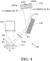
- the X-ray spectrometer 110 of the prior application is provided with, as shown in FIG. 1 , a sample holder 111 for holding a sample S, an excitation source 112, a slit member 113, a spectroscopic crystal 114, and an X-ray linear sensor 115.
- the sample S may be a solid sample, a liquid sample or a gas sample, and as the sample holder 111, a sample holder corresponding to the state of the sample is used.
- the excitation source 112 is an X-ray source for irradiating X-rays, which are excitation light (excitation rays), to a sample S.
- X-rays excitation light
- an electron beam source may be used.
- excitation light is irradiated to the planar irradiation area A on the sample S.
- the excitation light is vertically irradiated to the irradiation area A, but the excitation light may be irradiated at an inclined angle with respect to the irradiation area A.
- the slit member 113 is arranged between the irradiation area A and the spectroscopic crystal 114.
- the spectroscopic crystal 114 a spectroscopic crystal in which the distance between crystal surfaces which causes the Bragg reflection is minimum, i.e., the crystal surface with the smallest diffraction angle is parallel to the crystal surface is used.
- the slit member 113 is arranged parallel to (vertically to the paper surface in FIG.
- this crystal surface is called a "prescribed crystal surface”.
- the X-ray linear sensor 115 is configured such that a plurality of linear detection elements 1151 having a length in a direction parallel to the longitudinal direction of the slit (perpendicular to the paper surface of FIG. 1 ) are arranged in a direction perpendicular to the longitudinal direction of the slit.
- Each detection element 1151 only needs to detect the intensity of the X-rays incident thereon, and the function of detecting the wavelength or the energy of the incident X-rays is not necessary.
- the characteristic X-rays emitted from the linear portion A1 shown in FIG. 1 and FIG. 2 are incident on the spectroscopic crystal 114 at one incident angle (90- ⁇ 1 )° and the characteristic X-rays emitted from another linear portion A2 is incident on the spectroscopic crystal 114 at another incident angle (90- ⁇ 2 )°.
- the characteristic X-rays diffracted (reflected) by the spectroscopic crystal 114 are detected by one of the detection elements 1151 of the X-ray linear sensor 115.
- the characteristic X-rays are incident on the spectroscopic crystal 114 at a specific one incident angle (90- ⁇ )° which differs depending on the linear portion within the irradiation area A. Therefore, only the characteristic X-rays having a specific wavelength which differs for each linear portion are incident on the X-ray linear sensor 115 and detected by a different detection element 1151. For example, in the characteristic X-rays emitted from the linear portion A1 shown in FIG. 1 and FIG.
- the upper and lower limits of the measurable wavelength range are determined by the wavelength (specific wavelength) of the characteristic X-rays emitted from the linear portions A positioned at both end portions of the irradiation area and diffracted by the prescribed crystal surface of the spectroscopic crystal 114. Therefore, the characteristic X-rays having a wavelength outside the measureable wavelength range cannot be detected. For this reason, the types of elements that can be analyzed by a single device are limited.
- the range of the X-ray linear sensor 115 expected by the spectroscopic crystal 114 is limited, when the position and the orientation of the spectroscopic crystal 114 for characteristic X-rays of a specific wavelength emitted from a specific linear portion A1 are set, even if characteristic X-rays of another wavelength emitted from other linear portions A2 are incident on the spectroscopic crystal 114 at an angle satisfying the Bragg reflection condition, there are some cases in which the diffracted X-rays cannot be received and detected by the X-ray linear sensor 115. Furthermore, it is not possible to increase the detection sensitivity to measure trace elements, or to increase the wavelength (energy) resolution to perform a high precision measurement.
- the present inventors have configured the X-ray spectrometer according to the present invention in order to solve the problem that only the measurement of a predetermined condition can be performed by the prior application X-ray spectrometer 110.
- the examples will be described. Note that in each example, the same constituent element as that of the prior application X-ray spectrometer 110 is allotted by the same reference numeral, and the description thereof will be omitted as appropriate.
- the X-ray spectrometer 10 of Example 1 is provided with a first rotation mechanism 212 for rotating the spectroscopic crystal 14 and a second rotation mechanism 312 for rotating the X-ray linear sensor 15.
- the first rotation mechanism 212 is configured to change the angle formed by the prescribed crystal surface of the spectroscopic crystal 14.
- the second rotation mechanism 312 has a rotation center common to the first rotation mechanism 212, and is configured to rotate the X-ray linear sensor 15 so as to rotate the X-ray linear sensor 15 by 2 ⁇ in response to the rotation of the angle ⁇ of (the prescribed crystal surface) of the spectroscopic crystal 14 by the first rotation mechanism 212. That is, the first rotation mechanism 212 and the second rotation mechanism 312 are a so-called goniometer.
- the first moving mechanism according to the present invention is configured by the first rotation mechanism 212
- the second moving mechanism is configured by the second rotation mechanism 312.
- the angle formed by the prescribed crystal surface of the spectroscopic crystal 14 with respect to the surface of the sample S placed on the sample holder 11 can be changed by the first rotation mechanism 212. With this, it is possible to change the wavelength of the X-rays satisfying the condition of the Bragg reflection at the prescribed crystal surface among the X-rays emitted from each linear portion within the irradiation area of the sample S. In the X-ray spectrometer 10 of Example 1, it is possible to detect the X-rays of different wavelengths emitted from the same position within the irradiation area of the sample S, and it is also possible to detect the X-rays of the same wavelength emitted from different positions of the sample surface.
- the X-ray spectrometer 10A of Example 2 is also configured such that the types of measurable elements can be appropriately changed by changing the angle of the prescribed crystal surface of the spectroscopic crystal 14 with respect to the surface of sample S, but the configurations of the first moving mechanism 21A and the second moving mechanism 31A are different from Example 1.
- the first moving mechanism 21A is configured by a first linear motion mechanism 211A and a first rotation mechanism 212A
- the second moving mechanism 31A is configured by a second linear motion mechanism 311A and a second rotation mechanism 312A.
- the X-ray spectrometer 10A of Example 2 is designed based on the following concept. Here, it is assumed that the specification of the X-ray linear sensor 15 (1280 ch, distance of 0.05 mm between detection elements) is determined in advance.
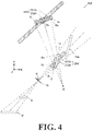
- FIG. 4 shows the arrangement of each constituent element forming the optical path of the X-rays emitted from the irradiation area A of the sample S in the X-ray spectrometer 10A of Example 2. In FIG. 4 , note that the descriptions of the sample holder 11 and the irradiation unit 12 are omitted.
- the center wavelength ⁇ M in the measurement range is determined. From this center wavelength ⁇ M and the surface distance d of the prescribed crystal surface, based on the condition of the Bragg reflection, the incident angle ⁇ M of the X-rays incident from the sample S on the central portion of the spectroscopic crystal 14 through the slit is determined. Then, with this, the orientation (the angle with respect to the surface of the sample S) of the prescribed crystal surface of the spectroscopic crystal 14 is determined.
- the minimum energy E L (longest wavelength ⁇ L ) in the measurement range is determined, and the optical path length from the slit to the X-ray linear sensor 15 is determined so that the light of the longest wavelength ⁇ L is incident on one end portion D L of the X-ray linear sensor 15.
- the spectroscopic crystal 14 can be placed at the position shown by the symbol 14a in FIG. 4 .
- the distance from the spectroscopic crystal 14 to the X-ray linear sensor 15 is appropriately changed according to the position of the spectroscopic crystal 14 so that the optical path length does not change.
- the size of the spectroscopic crystal 14 to be used is determined.
- the position of the spectroscopic crystal 14 is determined.
- the wavelength ⁇ satisfying the condition of the Bragg reflection at one end portion (the end portion opposite to the side on which the longest wavelength ⁇ L is incident) of the spectroscopic crystal 14 becomes the shortest wavelength ⁇ H (maximum energy E H ) in this arrangement.
- the relative positional relationship between the slit member 13, the spectroscopic crystal 14, and the X-ray linear sensor 15 (collectively referred to as a "measurement optical system") is determined.
- sample S sample holder 11
- the measurement optical system is determined.
- the position and the size of the irradiation area A on the surface of the sample S are determined (see the symbol S and the symbol S' in FIG. 4 ).
- the low energy first classification is a classification assuming the measurement of the characteristic X-rays emitted from V, Cr, Mn, Nd-Eu, and Gd, the minimum energy E L in the measurement range is 4.9 keV, the center energy E M (the X-ray energy of the above center wavelength ⁇ M ) is 5.5 keV, the maximum energy E H is 6.132 keV, and the energy resolution is 0.937 eV. Further, in the coordinate system shown in FIG.
- the low energy second classification (Low 2) is a classification assuming the measurement of the characteristic X-rays emitted from Mn, Fe, Co, Ni, Cu, Gd, Td, Dy-Hf, the minimum energy E L in the measurement range is 5.98 keV, the center energy E M is 7.0 keV, the maximum energy E H is 8.058 keV, and the energy resolution is 1.594 eV. Further, in the coordinate system shown in FIG.
- the middle energy first classification (Middle 1) is a classification assuming the measurement of the characteristic X-rays emitted from Ni-As, Se, Ta, W-Pt, Au, Hg-Pb-At, the minimum energy E L in the measurement range is 7.96 keV, the center energy E M is 9.75 keV, the maximum energy E H is 11.58 keV, and the energy resolution is 2.797 eV. Further, in the coordinate system shown in FIG.
- the high energy first classification (High 1) is a classification assuming the measurement of the characteristic X-rays emitted from Nd-Cd, In, Sn, U-Pu, Am-Lr, the minimum energy E L in the measurement range is 15.88 keV, the center energy E M is 20.75 keV, the maximum energy E H is 25.65 keV, and the energy resolution is 7.609 eV. Further, in the coordinate system shown in FIG.
- each member is arranged according to the above concept, since X-rays are not incident on a part of the high energy side of 1280 detection elements of the X-ray linear sensor 15, the value obtained by dividing the measurement energy range by the resolution is different from the number of channels (1280) of the X-ray linear sensor 15.
- a value obtained by dividing the range from the minimum energy E L to the center energy E M by half of the number of channels 640 is defined as resolution ⁇ E.
- FIG. 5 is obtained by plotting the center of the spectroscopic crystal 14 and the center position of the X-ray linear sensor 15 based on the results.
- the horizontal axis denotes a coordinate in the X-direction in FIG. 4
- the vertical axis denotes a coordinate in the Y-direction in FIG 4 . From this graph, it can be understood that the coordinates of the center positions of the spectroscopic crystals 14 are positioned on a straight line. Therefore, it can be understood that it is enough that the spectroscopic crystal 14 is moved to the coordinate position by the first linear motion mechanism 211A and inclined to a predetermined angle (determined by the above design) by the first rotation mechanism 212A.
- the first moving mechanism 21A may be configured by only the first rotation mechanism 212A.
- Example 1 When the diffraction angle degree in different wavelength ranges is determined based on the conditional expression of the Bragg reflection, in cases where the optical path length from the irradiation area of the sample S to the X-ray linear sensor 15 is constant, the resolution deteriorates as the X-rays to be measured become a short wavelength (high energy). That is, as in Example 1, when the first moving mechanism is constituted only by the first rotation mechanism 212 and the second moving mechanism is constituted only by the second rotation mechanism 312, since the optical path length does not change, the wavelength (energy) resolution deteriorates as the characteristic X-rays to be measured become higher energy. On the other hand, in Example 2, as shown in FIG.
- the measurement can be performed with higher resolution than in Example 1 in the short wavelength (high energy) region.
- Example 2 an example is described in which it is assumed that the characteristic X-rays having energy of 5 keV or more are measured, but the same concept can be used in measuring the characteristic X-rays having energy less than 5 keV.
- the types of the X-ray linear sensor 15 that can be used are different between the energy region of 5 keV or more and the energy region of less than 5 keV.
- a silicon strip detector (SSD) is used as the X-ray linear sensor 15, but this cannot be used as it is in the energy region of less than 5 keV.
- a CCD detector In the energy region of less than 5 keV, it is necessary to use, for example, a CCD detector as the X-ray linear sensor 15.
- the wavelength range is too wide (the ratio of the longest wavelength to the shortest wavelength is about 27 times). Therefore, when detecting all X-rays satisfying the condition of the Bragg reflection only by a single spectroscopic crystal, a large number of CCD detectors must be arranged, which makes the apparatus expensive. Therefore, in such a case, it is preferable to switch and use a plurality of spectral crystals or artificial multilayer films different in grating constant as the spectroscopic crystal 14.
- the first moving mechanism 21A can be configured only by the first rotation mechanism 212A.
- the first moving mechanism 21A can also be configured by the first linear motion mechanism 211A and the first rotation mechanism 212A.
- Example 3 is characterized by the configuration of the slit member 13. Specifically, it is characterized in that the opening width of the slit member 13 is variable.
- the wavelength (energy) resolution deteriorates, but the X-rays pass through the slit and are diffracted by the spectroscopic crystal 14, so the light amount of X-rays incident on the X-ray linear sensor 15 increases. Therefore, for example, in the case of measuring a trace element, a high sensitivity measurement in which the opening width of the slit member 13 is enlarged is performed, and in the case of performing a precise analysis, a high resolution measurement can be performed by narrowing the opening width of the slit member 13. This can be performed by configuring, as shown in FIG.
- only one of the slit plates may be movable relative to the other, but in that case, since the central position of the slit changes, it is preferable to move the pair of slit plates 131 and 132 equally to change the opening width of the slit member 13 so that central position of the slit does not change.
- FIG. 8 shows the results of measuring the K ⁇ 1 line of Mn under four types of conditions (0.1 mm, 0.3 mm, 0.8 mm, 1.6 mm) with different slit widths.
- the above formula is a formula for obtaining the lower detection limit from one standard sample, wherein D is the concentration (%) of the standard sample, Ib is the background intensity (cps), Ip is the signal net intensity (cps), and t is the integration time (s).
- FIG. 8(a) shows a measurement result when the slit width was 0.1 mm, and the full width at half maximum (FWHM) was 4.5 eV, and the lower detection limit (LLD: Lower Limit of Detection) was 0.13%.
- FIG. 8(b) shows a measurement result when the slit width was 0.3 mm, and the full width at half maximum (FWHM) was 7.1 eV, and the lower detection limit was 0.079%.
- FIG. 8(c) shows a measurement result when the slit width was 0.8 mm, and the full width at half maximum (FWHM) was 20 eV, and the lower detection limit was 0.049%.
- FIG. 8(b) shows a measurement result when the slit width was 0.3 mm, and the full width at half maximum (FWHM) was 7.1 eV, and the lower detection limit was 0.079%.
- FIG. 8(c) shows a measurement result when the slit width was 0.8 mm, and the full width at half maximum (
- a specific wavelength measurement optical system 40 for measuring characteristic X-rays emitted from a specific element is added to the above-mentioned Examples 1 to 3.
- a specific wavelength measurement optical system including the X-ray spectrometer 10C of the modification as shown in FIG. 9 , X-rays emitted in various directions from the irradiation area of the sample S are introduced into the solar slit 41.
- the solar slit 41 is configured by arranging a plurality of flat partition wall plates in parallel, and only the light traveling in a direction parallel to the surface of the partition wall plate passes through the solar slit 41, so the parallel light traveling in the parallel direction is taken out.
- the X-ray spectrometer 10C of the modification by measuring the characteristic X-rays emitted from a plurality of target elements by any of the measurement optical systems described in Examples 1 to 3, and further measuring the intensity of the characteristic X-rays emitted from the entire irradiation area of the sample S for one specific element, a high precision quantitative measurement, etc., can be performed.
- Example 2 the design concept described in Example 2 is an example, and the arrangement of each component can be determined by another procedure.
- Example 2 is configured so as not to use all detection elements of the X-ray linear sensor 15, it is also possible to design a measurement optical system so as to use all detection elements.
- an X-ray spectrometer may be configured to provide the configurations of Examples 1 to 3.
- it may be configured such that a plurality of specific wavelength measurement optical systems described in the modification are provided to measure characteristic X-rays emitted from specific elements.
- the degree of freedom of measurements can be increased by changing various measurement parameters by appropriately using the first moving mechanism and the second moving mechanism by changing the wavelength (energy) of measurements by changing the wavelength width of X-rays incident on each of the plurality of detection elements configuring the incident surface of the X-ray linear sensor by changing the optical path length that the characteristic X-rays emitted from the irradiation region of the sample are incident on the X-ray linear sensor by changing the distance from the sample surface to the prescribed crystal surface by the first moving mechanism while fixing the relative positional relationship between the spectroscopic crystal and the X-ray linear sensor.
Landscapes
- Chemical & Material Sciences (AREA)
- Physics & Mathematics (AREA)
- General Health & Medical Sciences (AREA)
- Life Sciences & Earth Sciences (AREA)
- Analytical Chemistry (AREA)
- Biochemistry (AREA)
- Health & Medical Sciences (AREA)
- General Physics & Mathematics (AREA)
- Immunology (AREA)
- Pathology (AREA)
- Crystallography & Structural Chemistry (AREA)
- Dispersion Chemistry (AREA)
- Spectroscopy & Molecular Physics (AREA)
- Analysing Materials By The Use Of Radiation (AREA)
Applications Claiming Priority (1)
| Application Number | Priority Date | Filing Date | Title |
|---|---|---|---|
| PCT/JP2017/018701 WO2018211664A1 (ja) | 2017-05-18 | 2017-05-18 | X線分光分析装置 |
Publications (2)
| Publication Number | Publication Date |
|---|---|
| EP3627146A1 true EP3627146A1 (de) | 2020-03-25 |
| EP3627146A4 EP3627146A4 (de) | 2020-05-13 |
Family
ID=64273507
Family Applications (1)
| Application Number | Title | Priority Date | Filing Date |
|---|---|---|---|
| EP17909827.2A Withdrawn EP3627146A4 (de) | 2017-05-18 | 2017-05-18 | Röntgenspektrometer |
Country Status (6)
| Country | Link |
|---|---|
| US (1) | US11112371B2 (de) |
| EP (1) | EP3627146A4 (de) |
| JP (1) | JP6874835B2 (de) |
| KR (1) | KR20200002951A (de) |
| CN (1) | CN110678743B (de) |
| WO (1) | WO2018211664A1 (de) |
Cited By (1)
| Publication number | Priority date | Publication date | Assignee | Title |
|---|---|---|---|---|
| US11137360B2 (en) | 2017-09-27 | 2021-10-05 | Shimadzu Corporation | X-ray spectrometer and chemical state analysis method using the same |
Families Citing this family (23)
| Publication number | Priority date | Publication date | Assignee | Title |
|---|---|---|---|---|
| US10295485B2 (en) | 2013-12-05 | 2019-05-21 | Sigray, Inc. | X-ray transmission spectrometer system |
| CN110678743B (zh) | 2017-05-18 | 2022-06-24 | 株式会社岛津制作所 | X射线分光分析装置 |
| CN112424591B (zh) | 2018-06-04 | 2024-05-24 | 斯格瑞公司 | 波长色散x射线光谱仪 |
| DE112019003777B4 (de) | 2018-07-26 | 2025-09-11 | Sigray, Inc. | Röntgenreflexionsquelle mit hoher helligkeit |
| US11056308B2 (en) | 2018-09-07 | 2021-07-06 | Sigray, Inc. | System and method for depth-selectable x-ray analysis |
| JP7182749B2 (ja) | 2019-09-03 | 2022-12-02 | シグレイ、インコーポレイテッド | コンピュータ断層撮影蛍光x線撮像のためのシステムおよび方法 |
| US11175243B1 (en) | 2020-02-06 | 2021-11-16 | Sigray, Inc. | X-ray dark-field in-line inspection for semiconductor samples |
| JP7144475B2 (ja) * | 2020-03-30 | 2022-09-29 | 日本電子株式会社 | 分析方法および分析装置 |
| WO2021237237A1 (en) | 2020-05-18 | 2021-11-25 | Sigray, Inc. | System and method for x-ray absorption spectroscopy using a crystal analyzer and a plurality of detector elements |
| JP7380421B2 (ja) * | 2020-05-27 | 2023-11-15 | 株式会社島津製作所 | X線分析装置およびx線分析方法 |
| WO2022061347A1 (en) | 2020-09-17 | 2022-03-24 | Sigray, Inc. | System and method using x-rays for depth-resolving metrology and analysis |
| KR20260030946A (ko) | 2020-12-07 | 2026-03-06 | 시그레이, 아이엔씨. | 투과 x-선 소스를 이용한 고처리량 3D x-선 이미징 시스템 |
| US12480892B2 (en) | 2020-12-07 | 2025-11-25 | Sigray, Inc. | High throughput 3D x-ray imaging system using a transmission x-ray source |
| WO2023017636A1 (ja) * | 2021-08-10 | 2023-02-16 | 株式会社島津製作所 | X線分析装置 |
| WO2023168204A1 (en) | 2022-03-02 | 2023-09-07 | Sigray, Inc. | X-ray fluorescence system and x-ray source with electrically insulative target material |
| US11992350B2 (en) | 2022-03-15 | 2024-05-28 | Sigray, Inc. | System and method for compact laminography utilizing microfocus transmission x-ray source and variable magnification x-ray detector |
| WO2023215204A1 (en) | 2022-05-02 | 2023-11-09 | Sigray, Inc. | X-ray sequential array wavelength dispersive spectrometer |
| DE112024000873T5 (de) | 2023-02-16 | 2026-01-15 | Sigray, Inc. | Röntgen-detektorsystem mit mindestens zwei gestapelten flachen bragg-diffraktoren |
| US12181423B1 (en) | 2023-09-07 | 2024-12-31 | Sigray, Inc. | Secondary image removal using high resolution x-ray transmission sources |
| US12429437B2 (en) | 2023-11-07 | 2025-09-30 | Sigray, Inc. | System and method for x-ray absorption spectroscopy using spectral information from two orthogonal planes |
| WO2025151383A1 (en) | 2024-01-08 | 2025-07-17 | Sigray, Inc. | X-ray analysis system with focused x-ray beam and non-x-ray microscope |
| WO2025155719A1 (en) | 2024-01-18 | 2025-07-24 | Sigray, Inc. | Sequential array of x-ray imaging detectors |
| WO2025174966A1 (en) | 2024-02-15 | 2025-08-21 | Sigray, Inc. | System and method for generating a focused x‑ray beam |
Family Cites Families (28)
| Publication number | Priority date | Publication date | Assignee | Title |
|---|---|---|---|---|
| DE1472229B2 (de) * | 1965-12-23 | 1970-05-27 | Siemens AG, 1000 Berlin u. 8000 München | Röntgenspektrometer-Zusatzeinrichtung für ein Korpuskularstrahlgerät, insbesondere ein Elektronenmikroskop |
| US3663812A (en) | 1969-02-27 | 1972-05-16 | Mc Donnell Douglas Corp | X-ray spectrographic means having fixed analyzing and detecting means |
| US4362935A (en) | 1979-02-09 | 1982-12-07 | Martin Marietta Corporation | Field portable element analysis unit |
| SU868503A1 (ru) * | 1980-01-29 | 1981-09-30 | Предприятие П/Я М-5912 | Рентгеновский спектрометр |
| JPS5788354A (en) * | 1980-11-21 | 1982-06-02 | Shimadzu Corp | X-ray analysing apparatus |
| GB2208925A (en) * | 1987-08-25 | 1989-04-19 | Le N Proizv Ob Burevestnik | Multichannel x-ray spectrometer |
| JPH0382943A (ja) * | 1989-08-25 | 1991-04-08 | Nec Corp | 全反射蛍光x線分析装置 |
| GB9223592D0 (en) * | 1992-11-11 | 1992-12-23 | Fisons Plc | X-ray analysis apparatus |
| EP0800647A1 (de) * | 1995-10-03 | 1997-10-15 | Koninklijke Philips Electronics N.V. | Apparat zur gleichzeitigen beugungs- und fluoreszenz-messungen mittels röntgenstrahlen |
| DE19603000A1 (de) | 1996-01-27 | 1997-07-31 | Philips Patentverwaltung | Verfahren zum Kalibrieren einer Anordnung zur Ermittlung des Impulsübertragsspektrums und Kalibriereinheit zur Durchführung des Verfahrens |
| JP3511826B2 (ja) * | 1997-01-23 | 2004-03-29 | 株式会社島津製作所 | 蛍光x線分析装置 |
| JP3639855B2 (ja) * | 1998-10-30 | 2005-04-20 | 理学電機工業株式会社 | 蛍光x線分析装置 |
| JP2002189004A (ja) * | 2000-12-21 | 2002-07-05 | Jeol Ltd | X線分析装置 |
| JP2002214165A (ja) * | 2001-01-17 | 2002-07-31 | Japan Science & Technology Corp | 蛍光x線分光方法およびその装置 |
| JP2003098126A (ja) | 2001-09-26 | 2003-04-03 | Rigaku Industrial Co | 蛍光・回折共用x線分析装置 |
| JP5245299B2 (ja) * | 2007-06-18 | 2013-07-24 | 株式会社島津製作所 | 蛍光x線分析装置 |
| JP5320807B2 (ja) | 2008-04-25 | 2013-10-23 | 株式会社島津製作所 | 波長分散型x線分光器 |
| EP2442097A4 (de) * | 2009-07-01 | 2014-04-23 | Rigaku Denki Co Ltd | Röntgenvorrichtung, verfahren zu ihrer verwendung und röntgenbestrahlungsverfahren |
| JP2013096750A (ja) | 2011-10-28 | 2013-05-20 | Hamamatsu Photonics Kk | X線分光検出装置 |
| JP6009963B2 (ja) * | 2013-02-14 | 2016-10-19 | 日本電子株式会社 | 試料分析方法および試料分析装置 |
| JP2014209098A (ja) | 2013-03-25 | 2014-11-06 | 株式会社リガク | X線分析装置 |
| DE102013207160A1 (de) | 2013-04-19 | 2014-10-23 | Helmholtz-Zentrum Berlin Für Materialien Und Energie Gmbh | Vorrichtung und Verfahren zur Bestimmung der energetischen Zusammensetzung von elektromagnetischen Wellen |
| CN107110798B (zh) | 2014-12-25 | 2019-08-16 | 株式会社理学 | 掠入射荧光x射线分析装置和方法 |
| DE102016014213A1 (de) | 2015-12-08 | 2017-07-06 | Shimadzu Corporation | Röntgenspektroskopische analysevorrichtung und elementaranalyseverfahren |
| CN110678743B (zh) | 2017-05-18 | 2022-06-24 | 株式会社岛津制作所 | X射线分光分析装置 |
| WO2019064360A1 (ja) | 2017-09-27 | 2019-04-04 | 株式会社島津製作所 | X線分光分析装置、及び該x線分光分析装置を用いた化学状態分析方法 |
| WO2019163023A1 (ja) | 2018-02-21 | 2019-08-29 | 株式会社島津製作所 | 電池材料の化学状態分析装置及び方法 |
| JP2021012054A (ja) | 2019-07-04 | 2021-02-04 | 日本電子株式会社 | 蛍光x線分析装置及びその校正方法 |
-
2017
- 2017-05-18 CN CN201780090533.5A patent/CN110678743B/zh active Active
- 2017-05-18 US US16/612,092 patent/US11112371B2/en active Active
- 2017-05-18 JP JP2019518701A patent/JP6874835B2/ja active Active
- 2017-05-18 EP EP17909827.2A patent/EP3627146A4/de not_active Withdrawn
- 2017-05-18 KR KR1020197034353A patent/KR20200002951A/ko not_active Ceased
- 2017-05-18 WO PCT/JP2017/018701 patent/WO2018211664A1/ja not_active Ceased
Cited By (1)
| Publication number | Priority date | Publication date | Assignee | Title |
|---|---|---|---|---|
| US11137360B2 (en) | 2017-09-27 | 2021-10-05 | Shimadzu Corporation | X-ray spectrometer and chemical state analysis method using the same |
Also Published As
| Publication number | Publication date |
|---|---|
| EP3627146A4 (de) | 2020-05-13 |
| WO2018211664A1 (ja) | 2018-11-22 |
| JP6874835B2 (ja) | 2021-05-19 |
| JPWO2018211664A1 (ja) | 2019-11-07 |
| US11112371B2 (en) | 2021-09-07 |
| CN110678743A (zh) | 2020-01-10 |
| US20200225172A1 (en) | 2020-07-16 |
| KR20200002951A (ko) | 2020-01-08 |
| CN110678743B (zh) | 2022-06-24 |
Similar Documents
| Publication | Publication Date | Title |
|---|---|---|
| US11112371B2 (en) | X-ray spectrometer | |
| Schlesiger et al. | XAFS spectroscopy by an X-ray tube based spectrometer using a novel type of HOPG mosaic crystal and optimized image processing | |
| JP6673172B2 (ja) | X線分光分析装置及び元素分析方法 | |
| US8548123B2 (en) | Method and apparatus for using an area X-ray detector as a point detector in an X-ray diffractometer | |
| US6697454B1 (en) | X-ray analytical techniques applied to combinatorial library screening | |
| US11105756B2 (en) | X-ray diffraction and X-ray spectroscopy method and related apparatus | |
| RU2449262C2 (ru) | Рентгенодифракционная установка и способ рентгеновской дифракции | |
| CN111133302A (zh) | X射线分光分析装置及使用该x射线分光分析装置的化学状态分析方法 | |
| CN1823270A (zh) | 能量色散类型x射线衍射/光谱仪 | |
| US7092843B2 (en) | Apparatus and method for suppressing insignificant variations in measured sample composition data, including data measured from dynamically changing samples using x-ray analysis techniques | |
| US9329143B2 (en) | Method and apparatus for investigating the X-ray radiographic properties of samples | |
| CN116593509A (zh) | X射线衍射装置及测定方法 | |
| JP6009156B2 (ja) | 回折装置 | |
| Brügemann et al. | Detectors for X-ray diffraction and scattering: a user's overview | |
| US12523621B2 (en) | Parallel plate x-ray collimator having a variable acceptance angle and an x-ray analysis apparatus | |
| Sanyal et al. | Direct non-destructive trace and major elemental analysis in steel samples utilizing micro-focused bremsstrahlung radiation in X-ray fluorescence geometry | |
| Rijal et al. | Hyper-resolution in X-ray emission spectroscopy: integrating extended-range high energy resolution fluorescence detection and multiple-crystal spectrometry with advanced binary data splicing | |
| Holfelder et al. | A double crystal von Hamos spectrometer for traceable x-ray emission spectroscopy | |
| WO2003081222A1 (en) | Screening of combinatorial library using x-ray analysis | |
| Malaurent et al. | The determination of the period of magnetic multilayers by the X-ray energy dispersive diffraction method | |
| SU1087856A1 (ru) | Способ определени рассеивающей способности вещества | |
| Chang et al. | Combinatorial approach to ferroelectric/dielectric materials | |
| Turyanskiy et al. | An energy dispersion scheme based on a semiconductor X-ray spectrometer and a broadband monochromator for determining the content of heavy elements from the absorption spectra | |
| Bertin | X-Ray Emission Spectrometric Analysis: General Introduction |
Legal Events
| Date | Code | Title | Description |
|---|---|---|---|
| STAA | Information on the status of an ep patent application or granted ep patent |
Free format text: STATUS: THE INTERNATIONAL PUBLICATION HAS BEEN MADE |
|
| PUAI | Public reference made under article 153(3) epc to a published international application that has entered the european phase |
Free format text: ORIGINAL CODE: 0009012 |
|
| STAA | Information on the status of an ep patent application or granted ep patent |
Free format text: STATUS: REQUEST FOR EXAMINATION WAS MADE |
|
| 17P | Request for examination filed |
Effective date: 20191211 |
|
| AK | Designated contracting states |
Kind code of ref document: A1 Designated state(s): AL AT BE BG CH CY CZ DE DK EE ES FI FR GB GR HR HU IE IS IT LI LT LU LV MC MK MT NL NO PL PT RO RS SE SI SK SM TR |
|
| AX | Request for extension of the european patent |
Extension state: BA ME |
|
| A4 | Supplementary search report drawn up and despatched |
Effective date: 20200416 |
|
| RIC1 | Information provided on ipc code assigned before grant |
Ipc: G01N 23/223 20060101AFI20200408BHEP Ipc: G01N 23/207 20180101ALI20200408BHEP Ipc: G01N 23/22 20180101ALI20200408BHEP |
|
| DAV | Request for validation of the european patent (deleted) | ||
| DAX | Request for extension of the european patent (deleted) | ||
| STAA | Information on the status of an ep patent application or granted ep patent |
Free format text: STATUS: THE APPLICATION HAS BEEN WITHDRAWN |
|
| 18W | Application withdrawn |
Effective date: 20210330 |