EP3627179A1 - Steuerungsvorrichtung, abtastsystem, steuerungsverfahren und programm - Google Patents
Steuerungsvorrichtung, abtastsystem, steuerungsverfahren und programm Download PDFInfo
- Publication number
- EP3627179A1 EP3627179A1 EP18802676.9A EP18802676A EP3627179A1 EP 3627179 A1 EP3627179 A1 EP 3627179A1 EP 18802676 A EP18802676 A EP 18802676A EP 3627179 A1 EP3627179 A1 EP 3627179A1
- Authority
- EP
- European Patent Office
- Prior art keywords
- sensor
- vehicle
- specified object
- control device
- sensing result
- Prior art date
- Legal status (The legal status is an assumption and is not a legal conclusion. Google has not performed a legal analysis and makes no representation as to the accuracy of the status listed.)
- Withdrawn
Links
Images




Classifications
-
- G—PHYSICS
- G01—MEASURING; TESTING
- G01S—RADIO DIRECTION-FINDING; RADIO NAVIGATION; DETERMINING DISTANCE OR VELOCITY BY USE OF RADIO WAVES; LOCATING OR PRESENCE-DETECTING BY USE OF THE REFLECTION OR RERADIATION OF RADIO WAVES; ANALOGOUS ARRANGEMENTS USING OTHER WAVES
- G01S13/00—Systems using the reflection or reradiation of radio waves, e.g. radar systems; Analogous systems using reflection or reradiation of waves whose nature or wavelength is irrelevant or unspecified
- G01S13/88—Radar or analogous systems specially adapted for specific applications
- G01S13/93—Radar or analogous systems specially adapted for specific applications for anti-collision purposes
- G01S13/931—Radar or analogous systems specially adapted for specific applications for anti-collision purposes of land vehicles
-
- B—PERFORMING OPERATIONS; TRANSPORTING
- B60—VEHICLES IN GENERAL
- B60W—CONJOINT CONTROL OF VEHICLE SUB-UNITS OF DIFFERENT TYPE OR DIFFERENT FUNCTION; CONTROL SYSTEMS SPECIALLY ADAPTED FOR HYBRID VEHICLES; ROAD VEHICLE DRIVE CONTROL SYSTEMS FOR PURPOSES NOT RELATED TO THE CONTROL OF A PARTICULAR SUB-UNIT
- B60W30/00—Purposes of road vehicle drive control systems not related to the control of a particular sub-unit, e.g. of systems using conjoint control of vehicle sub-units
- B60W30/18—Propelling the vehicle
-
- G—PHYSICS
- G01—MEASURING; TESTING
- G01S—RADIO DIRECTION-FINDING; RADIO NAVIGATION; DETERMINING DISTANCE OR VELOCITY BY USE OF RADIO WAVES; LOCATING OR PRESENCE-DETECTING BY USE OF THE REFLECTION OR RERADIATION OF RADIO WAVES; ANALOGOUS ARRANGEMENTS USING OTHER WAVES
- G01S17/00—Systems using the reflection or reradiation of electromagnetic waves other than radio waves, e.g. lidar systems
- G01S17/02—Systems using the reflection of electromagnetic waves other than radio waves
- G01S17/06—Systems determining position data of a target
- G01S17/42—Simultaneous measurement of distance and other co-ordinates
-
- G—PHYSICS
- G01—MEASURING; TESTING
- G01S—RADIO DIRECTION-FINDING; RADIO NAVIGATION; DETERMINING DISTANCE OR VELOCITY BY USE OF RADIO WAVES; LOCATING OR PRESENCE-DETECTING BY USE OF THE REFLECTION OR RERADIATION OF RADIO WAVES; ANALOGOUS ARRANGEMENTS USING OTHER WAVES
- G01S17/00—Systems using the reflection or reradiation of electromagnetic waves other than radio waves, e.g. lidar systems
- G01S17/88—Lidar systems specially adapted for specific applications
- G01S17/93—Lidar systems specially adapted for specific applications for anti-collision purposes
-
- G—PHYSICS
- G01—MEASURING; TESTING
- G01S—RADIO DIRECTION-FINDING; RADIO NAVIGATION; DETERMINING DISTANCE OR VELOCITY BY USE OF RADIO WAVES; LOCATING OR PRESENCE-DETECTING BY USE OF THE REFLECTION OR RERADIATION OF RADIO WAVES; ANALOGOUS ARRANGEMENTS USING OTHER WAVES
- G01S7/00—Details of systems according to groups G01S13/00, G01S15/00, G01S17/00
- G01S7/48—Details of systems according to groups G01S13/00, G01S15/00, G01S17/00 of systems according to group G01S17/00
- G01S7/497—Means for monitoring or calibrating
- G01S7/4972—Alignment of sensor
-
- G—PHYSICS
- G05—CONTROLLING; REGULATING
- G05D—SYSTEMS FOR CONTROLLING OR REGULATING NON-ELECTRIC VARIABLES
- G05D1/00—Control of position, course, altitude or attitude of land, water, air or space vehicles, e.g. using automatic pilots
- G05D1/0088—Control of position, course, altitude or attitude of land, water, air or space vehicles, e.g. using automatic pilots characterized by the autonomous decision making process, e.g. artificial intelligence, predefined behaviours
-
- G—PHYSICS
- G08—SIGNALLING
- G08G—TRAFFIC CONTROL SYSTEMS
- G08G1/00—Traffic control systems for road vehicles
- G08G1/16—Anti-collision systems
-
- B—PERFORMING OPERATIONS; TRANSPORTING
- B60—VEHICLES IN GENERAL
- B60W—CONJOINT CONTROL OF VEHICLE SUB-UNITS OF DIFFERENT TYPE OR DIFFERENT FUNCTION; CONTROL SYSTEMS SPECIALLY ADAPTED FOR HYBRID VEHICLES; ROAD VEHICLE DRIVE CONTROL SYSTEMS FOR PURPOSES NOT RELATED TO THE CONTROL OF A PARTICULAR SUB-UNIT
- B60W2554/00—Input parameters relating to objects
-
- B—PERFORMING OPERATIONS; TRANSPORTING
- B60—VEHICLES IN GENERAL
- B60W—CONJOINT CONTROL OF VEHICLE SUB-UNITS OF DIFFERENT TYPE OR DIFFERENT FUNCTION; CONTROL SYSTEMS SPECIALLY ADAPTED FOR HYBRID VEHICLES; ROAD VEHICLE DRIVE CONTROL SYSTEMS FOR PURPOSES NOT RELATED TO THE CONTROL OF A PARTICULAR SUB-UNIT
- B60W2555/00—Input parameters relating to exterior conditions, not covered by groups B60W2552/00, B60W2554/00
- B60W2555/60—Traffic rules, e.g. speed limits or right of way
-
- G—PHYSICS
- G01—MEASURING; TESTING
- G01S—RADIO DIRECTION-FINDING; RADIO NAVIGATION; DETERMINING DISTANCE OR VELOCITY BY USE OF RADIO WAVES; LOCATING OR PRESENCE-DETECTING BY USE OF THE REFLECTION OR RERADIATION OF RADIO WAVES; ANALOGOUS ARRANGEMENTS USING OTHER WAVES
- G01S17/00—Systems using the reflection or reradiation of electromagnetic waves other than radio waves, e.g. lidar systems
- G01S17/88—Lidar systems specially adapted for specific applications
- G01S17/93—Lidar systems specially adapted for specific applications for anti-collision purposes
- G01S17/931—Lidar systems specially adapted for specific applications for anti-collision purposes of land vehicles
-
- G—PHYSICS
- G01—MEASURING; TESTING
- G01S—RADIO DIRECTION-FINDING; RADIO NAVIGATION; DETERMINING DISTANCE OR VELOCITY BY USE OF RADIO WAVES; LOCATING OR PRESENCE-DETECTING BY USE OF THE REFLECTION OR RERADIATION OF RADIO WAVES; ANALOGOUS ARRANGEMENTS USING OTHER WAVES
- G01S7/00—Details of systems according to groups G01S13/00, G01S15/00, G01S17/00
- G01S7/48—Details of systems according to groups G01S13/00, G01S15/00, G01S17/00 of systems according to group G01S17/00
- G01S7/497—Means for monitoring or calibrating
Definitions
- the present invention relates to a control device, a scanning system, a control method, and a program.
- Patent Document 1 mentioned below discloses an example of a technology related to the automated driving technology.
- Patent Document 1 mentioned below discloses a technology of determining a risk, based on a detection result of a sensor used for control of autonomous driving, and outputting information for causing a driver to terminate autonomous driving, based on the determined risk.
- Patent Document 1 Japanese Unexamined Patent application Publication No. 2015-230552
- Sensing performance of a sensor may be degraded due to aging or some malfunction.
- the aforementioned technology in Patent Document 1 assumes that sensing by a sensor is performed accurately and does not provide a solution to such a problem.
- the present invention has been made in view of the aforementioned problem, and an object of the present invention is to provide a technology of grasping a state of a sensor equipped on a vehicle.
- the invention according to claim 1 is a control device including:
- the invention according to claim 16 is a scanning system including:
- the invention according to claim 18 is a control method executed by a computer, the control method including:
- the invention according to claim 19 is a program for causing a computer to function as:
- each block in a block diagram represents a function-based configuration rather than a hardware-based configuration.
- Fig. 1 is a diagram for illustrating an outline of a control device 100 according to the present invention.
- the control device 100 according to the present invention may be a device equipped on a vehicle 500 (may be hereinafter also denoted as a "first vehicle 500") or may be an external device communicably connected to the first vehicle 500 through a communication network outside the vehicle. Further, part of functions of the control device 100, to be described below, may be provided by a device equipped on the first vehicle 500, and the remaining functions may be provided by an external device. An example of the control device 100 being equipped on the first vehicle 500 is illustrated in Fig. 1 .
- control device 100 is also communicably connected to a sensor 300 (unillustrated, and may be hereinafter also denoted as a "first sensor 300") equipped on the first vehicle 500.
- the first sensor 300 includes various sensors for detecting an object positioned around the first vehicle 500. A sensing result of an object by the first sensor 300 may be used as an input to a known algorithm for detecting surrounding obstacles or a known algorithm for estimating a self-position and an attitude of the first vehicle 500, in addition to being used for performance measurement of the sensor, to be described later.
- Sensing performance of the first sensor 300 may be degraded due to a state of the sensor such as aging degradation and internal temperature of the sensor, or an external environment (such as rain, fog, a cloud of dust, snow, or the westering sun). Further, degradation in sensing performance of the first sensor 300 appears in a form of a variation in a characteristic (such as a signal-to-noise ratio or a signal strength) of the sensing result.
- the control device 100 at least has a function of determining performance of the first sensor 300, based on a characteristic of the sensing result of an object used for measuring the performance of the first sensor 300 (may be hereinafter also denoted as a "specified object").
- control device 100 A specific configuration and a specific operation of the control device 100 will be described in each the following embodiments.
- Fig. 2 is a block diagram conceptually illustrating a functional configuration of a control device 100 according to a first embodiment.
- the control device 100 includes a first acquisition unit 110, a second acquisition unit 120, a detection unit 130, and a determination unit 140.
- the first acquisition unit 110 acquires a sensing result of an object from a first sensor 300 for detecting an object around a first vehicle 500. Further, the second acquisition unit 120 acquires positional information of a specified object.
- a specified object is an object used for performance measurement of the first sensor 300.
- a specified object may be a dedicated object provided for determining performance of a sensor equipped on each vehicle or may be a general object. In the case of the latter, for example, the specified object is an installation installed on the road (example: a signal, a delineator, a guardrail, a road sign, or a direction sign) or a marking on the road (a regulation marking or an instruction marking) .
- An installation, and a marking on the road may also be used for estimation processing of a position and an attitude of each vehicle.
- the detection unit 130 detects a specified object existing within a reference distance from the first vehicle 500, by use of positional information of the first vehicle 500 and positional information of a specified object.
- the determination unit 140 determines performance of the first sensor 300 by use of a sensing result a specified object by the first sensor 300.
- Each functional component in the control device 100 may be provided by hardware (example: a hardwired electronic circuit) providing each functional component or may be provided by a combination of hardware and software (example: a combination of an electronic circuit and a program controlling the electronic circuit) .
- hardware example: a hardwired electronic circuit
- software example: a combination of an electronic circuit and a program controlling the electronic circuit
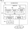
- Fig. 3 is a diagram illustrating a hardware configuration of the control device 100.
- a computer 200 is a computer providing the control device 100.
- the computer 200 is, for example, an electronic control unit (ECU) equipped on the first vehicle 500.
- ECU electronice control unit
- the control device 100 is a server device positioned outside the vehicle, or the like, the computer 200 is constructed as a general computer.
- the computer 200 includes a bus 202, a processor 204, a memory 206, a storage device 208, an input-output interface 210, and a network interface 212.
- the bus 202 is a data transmission channel for the processor 204, the memory 206, the storage device 208, the input-output interface 210, and the network interface 212 to mutually transmit and receive data.
- a method of interconnecting the processor 204 and the like is not limited to the bus connection.
- the processor 204 is an arithmetic processing unit provided by use of a microprocessor, a central processing unit (CPU), a graphics processing unit (GPU), or the like.
- the memory 206 is a main storage unit provided by use of a random access memory (RAM) or the like.
- the storage device 208 is an auxiliary storage unit provided by use of a read only memory (ROM), a flash memory, or the like.
- the storage device 208 may be configured with hardware similar to the hardware constituting the main storage unit, such as a RAM.
- the storage device 208 stores a program module for providing each functional component in the control device 100.
- the processor 204 provides a function of the control device 100 by reading the program module into the memory 206 and executing the program module.
- the storage device 208 may store map information used by the detection unit 110.
- the input-output interface 210 is an interface for connecting the computer 200 to peripheral equipment.
- the input-output interface 210 is connected to the first sensor 300 equipped on the first vehicle 500.
- the first sensor 300 is a sensor for detecting an object around the first vehicle 500.
- the first sensor 300 is an optical sensor measuring a distance and a direction from the first vehicle to an object by use of light (such as a pulse wave of light) .
- the first sensor 300 may be an image sensor using a charge-coupled device (CCD) or a complementary metal oxide semiconductor (CMOS), an acoustic sensor using a piezoelectric vibrator, or the like.
- the present invention may be provided as a scanning system including the control device 100 and the first sensor 300. When the first sensor is a sensor using light, the scanning system may be referred to as a so-called light detection and ranging (Lidar) system.
- Lidar light detection and ranging
- the network interface 212 is an interface for connecting the computer 200 to a communication network.
- the communication network is a Controller Area Network (CAN) or a Wide Area Network (WAN).
- a method of connecting the network interface 212 to the communication network may be a wireless connection or a wired connection.
- the control device 100 can communicate with an ECU on the first vehicle 500 or an unillustrated server device through the network interface 212.
- the configuration of the present embodiment described above allows determination of performance of the first sensor 300 equipped on the first vehicle 500. Further, the configuration of the present embodiment described above allows determination of performance of the first sensor 300 in real time while the first vehicle 500 is traveling.
- Fig. 4 is a flowchart illustrating an operation example of the control device 100 according to the first embodiment. For example, processing described below is repeatedly executed at predetermined intervals while the first vehicle 500 is traveling.
- the first acquisition unit 110 acquires a sensing result of an obj ect positioned around the first vehicle 500 from the first sensor 300 (S102).
- the second acquisition unit 120 acquires positional information of a specified object (S104).
- positional information of each specified object is stored in a predetermined table and is further stored in a predetermined storage unit.
- positional information of a specified object may be stored in association with map information. For example, by preparing, as a type of information included in map information about an object, flag information indicating whether or not the object is a specified object, or information allowing identification of a specified object (such as an identifier of the specified object), positional information of the specified object can be associated with the map information.
- a specified object is a public property installed on a road (such as a signal, a delineator, a guardrail, a road sign, or a direction sign), a marking on a road (such as a regulation marking or an instruction marking), or the like.
- a road sign or a direction sign using a retroreflective material is preferable as a specified object from a viewpoint of a capability of efficiently receiving reflected light.
- the second acquisition unit 120 may acquire relative positional information between the first vehicle 500 (first sensor 300) and a specified object.
- a specified object is installed at a position being a predetermined distance apart from a stop position of the first vehicle 500 in a factory performing maintenance of an accessory of the first vehicle 500, or the like, and the second acquisition unit 120 acquires information indicating the predetermined distance as "relative positional information between the first vehicle 500 (first sensor 300) and the specified object.”
- reference performance (such as a signal-to-noise ratio or a signal strength) based on the predetermined distance is previously prepared in a predetermined storage area, and by comparison with reference performance read from the storage area, the determination unit 140 can evaluate performance of the first sensor 300.
- the second acquisition unit 120 may acquire map information of the inside of the factory and positional information (or position-attitude information) of the specified object.
- the map information of the inside of the factory and the positional information (or the position-attitude information) of the specified object are stored in a predetermined server device, and by communicating with the server device, the second acquisition unit 120 may acquire the aforementioned map information and the aforementioned positional information of the specified object or position-attitude information.
- the determination unit 140 can evaluate performance of the first sensor 300 by reading reference performance data to be compared from the predetermined storage area, based on the pieces of information described above and positional information of the own vehicle estimated in the factory, and comparing the reference performance data with an actual measurement result.
- the detection unit 130 acquires positional information of the first vehicle 500 (S106) .
- the detection unit 130 may be configured to be able to calculate positional information of the first vehicle 500 by use of a known algorithm estimating a self-position and an attitude, based on a Bayesian estimation, or may be configured to be able to acquire positional information of the first vehicle 500 generated by another unillustrated processing unit.
- the detection unit 130 determines whether or not a specified object positioned within a reference distance from the first vehicle 500 exists (S108) .
- a specified object does not exist within the reference distance from the first vehicle 500 (S108: NO)
- subsequent processing is not executed.
- the detection unit 130 outputs information allowing identification of the specified object (such as an identifier uniquely assigned to each specified object) to the determination unit 140 (S110).
- information indicating a reference distance is previously stored in a storage unit such as the memory 206 or the storage device 208.
- the detection unit 130 may be configured to change a reference distance according to a vehicle speed.
- the detection unit 130 can acquire a traveling speed of the first vehicle 500 through a CAN of the first vehicle 500, correct a reference distance stored in the storage unit, based on the traveling speed, and use the corrected reference distance. In this case, the detection unit 130 makes the correction in such a way that as the vehicle speed becomes faster, the reference distance becomes longer.
- a plurality of reference distances based on vehicle speeds may be previously stored in a storage unit such as the memory 206 or the storage device 208, and the detection unit 130 may be configured to read a reference distance based on an acquired speed of the first vehicle 500.
- performance of the first sensor 300 can be determined within a distance based on a vehicle speed.
- the determination unit 140 acquires a sensing result of the specified object detected in the processing in S110 (S112).
- the determination unit 140 can calculate an estimated position of the specified object within a sensing range of the first sensor 300, based on information indicating a position and an attitude of the first vehicle 500 and map information, and can extract a signal in an area related to the specified object out of output signals of the first sensor 300, based on the estimated position.
- the determination unit 140 can correct the estimated area, based on an actual sensing result. For example, the determination unit 140 can correct the roughly estimated area from spatial continuity between a detection distance or a signal strength expected for an output of the first sensor 300 with respect to the specified object, and the actual sensing result.
- the sensing result of the specified object by the first sensor 300 includes information indicating a distance from the first vehicle 500 to the specified object and information indicating a characteristic (for example, a signal-to-noise ratio or a signal strength) of the output signal of the first sensor 300.
- the sensing result of the specified object is acquired as information with respect to a plurality of points on a surface of the specified object.
- the determination unit 140 may use an average of sensing results at the plurality of points on the surface of the specified object as a sensing result of the specified object. Further, the determination unit 140 may select a sensing result at a distance closest to the reference distance out of the sensing results with respect to the plurality of points on the surface of the specified object and use the sensing result in performance determination processing of the first sensor 300, to be described later.
- the determination unit 140 acquires reference performance data associated with the specified object detected by the detection unit 130 (S114). For example, reference performance data related to each specified object is stored in association with information allowing identification of the specified object (such as an identifier of the specified object) as illustrated in Fig. 5.
- Fig. 5 is a diagram illustrating an example of a storage unit storing reference performance data. The determination unit 140 can read reference performance data, based on an identifier of a specified object acquired from the detection unit 130.
- Reference performance data is data indicating a signal-to-noise ratio or a signal strength of an output signal of the first sensor 300 based on a distance to a specified object and is associated with each specified object in a form of a predetermined table or function. In the example in Fig. 5 , reference performance data is associated in a format of a function. Reference performance data vary with a sensor equipped on a vehicle and therefore may be prepared for each sensor or each device equipped with the sensor. A case of using the same sensor is herein assumed for simplification of description.
- the determination unit 140 can acquire distance reference performance data included in the sensing result acquired in the processing in S102.
- a distance from the first vehicle 500 to the specified object may not be included in the sensing result.
- a sensing result image data
- the determination unit 140 can calculate a difference distance between the positional information of the specified object acquired in the processing in S104 and the positional information of the first vehicle 500 acquired in the processing in S106, and acquire reference performance data based on the difference distance.
- the determination unit 140 may estimate a distance from the first sensor 300 to the specified object and use the estimated distance as a distance from the first vehicle 500 to the specified object.
- the reference performance data is data based on a sensing result of a specified object by the first sensor 300 in a predetermined external environment (test environment).
- the reference performance data is test-measurement data of a specified object by the first sensor 300 in an ideal state.
- the ideal state refers to a state in which an effect of an external environment (such as an effect of external light [the westering sun], rain, fog, a cloud of dust, or snow) on performance of the first sensor 300 does not exist, and also aging degradation of the sensor does not exist (for example, a state at initial shipping).
- the reference performance data may be determined based on a single test result or may be determined based on a statistic (such as a maximum value, a median, a mode, or an average) of a plurality of test measurement results.
- a plurality of types of reference performance data may be prepared by performing measurements in various test environments with different conditions. For example, a plurality of types of reference performance data such as first reference data acquired by a test measurement in the ideal state, second reference performance data acquired by a test measurement in a darkroom, third reference performance data acquired by a test measurement in an environment assuming the nighttime, and fourth reference performance data in an environment assuming cloudiness in the daytime may be prepared. Further, the reference performance data may be determined based on a performance value theoretically derived from a product specification of the first sensor 300.
- the determination unit 140 may also calculate the reference performance data by use of the information indicating a physical characteristic of each individual specified object.
- a function or a table for calculating reference performance data by use of information indicating a physical characteristic of a specified object is previously prepared in the memory 206 or the storage device 208.
- the determination unit 140 determines performance of the first sensor 300, based on a result of comparing an actual sensing result of the specified object acquired in the processing in S112 with reference performance data associated with the specified object acquired in the processing in S114 (S116).
- the determination unit 140 can determine an estimated value (such as a decibel value or a ratio) of performance of the first sensor 300, on the basis of a signal-to-noise ratio or a signal strength based on a distance to the specified object, the ratio or the strength being indicated by the reference performance data, and output information indicating the determination result. Specifically, the determination unit 140 can output information indicating "N [dB] degradation with respect to the reference performance.”
- each specified object may become unsuited for performance measurement of the first sensor 300 due to a state (such as adhesion of dirt, deformation, or degradation of the surface) of the specified object or a surrounding environment.
- the detection unit 130 may have a function of excluding such a specified object unsuited for performance measurement of the first sensor 300 from a detection target.
- the detection unit 130 may exclude a specified object not satisfying a predetermined criterion from a detection target by use of history data of a sensing result of the specified object.
- the predetermined criterion is "a probability of acquiring a sensing result equivalent (for example, 90% or greater) to a signal-to-noise ratio or a signal strength indicated by reference performance data associated with the specified object is less than or equal to a certain ratio (for example, 30%)."
- the detection unit 130 can improve performance measurement precision of the first sensor 300.
- control device 100 When the control device 100 is an on-vehicle device, history data of a sensing result of a specified object is kept in, for example, a server device (unillustrated) on an external network. Further, when the control device 100 is an external server device, history data of a sensing result of a specified object is kept in the memory 206 or the storage device 208 in the computer 200 providing the control device 100.
- the sensing result (a distance to the specified object and a signal-to-noise ratio or a signal strength of a signal) is sent to the server device along with identification information of the specified object.
- history data of the sensing result of the specified object is generated and updated. Further, information indicating a time and the weather when sensing is performed on the specified object and information for identifying the sensor may be further transmitted to the control device 100 functioning as a server device or the server device on the external network.
- the detection unit 130 can narrow down the history data by conditions such as the weather or a time, and precisely determine whether or not the specified object is suited for performance measurement of the first sensor 300.
- information indicating a degradation state of the sensor performing the sensing may be further transmitted to the control device 100 functioning as a server device or the server device on the external network.
- the detection unit 130 may exclude data related to a degraded sensor, based on the information indicating a degradation state of the sensor. Thus, by excluding data in which a cause of a sensing result equivalent to reference performance data not being acquired is at least degradation of a sensor, whether or not a specified object is suited for performance measurement of the first sensor 300 can be more precisely determined.
- the detection unit 130 can sort out a specified object to be a detection target, by use of information indicating an inclination of a specified object. Specifically, the detection unit 130 can sort out a specified object to be a detection target, based on an inclination of a specified object relative to the first vehicle 500 or a road on which the first vehicle 500 is traveling. For example, the detection unit 130 can identify a current attitude of the first vehicle 500 (a direction the first vehicle 500 is directed to) by use of the first sensor 300 or another inertial measurement device, and calculate a degree of inclination of the specified object relative to the first vehicle 500, based on information about the attitude of the first vehicle 500 and information indicating a direction of the specified object, the information about the direction being stored in map information.
- the detection unit 130 may assume an extending direction of a road on which the first vehicle 500 is currently traveling as an attitude of the first vehicle 500 and simply calculate a degree of inclination of a specified object relative to the road as a degree of inclination of the specified object relative to the first vehicle 500.
- the detection unit 130 can determine the extending direction of the road on which the first vehicle 500 is currently traveling, based on information indicating a current position of the first vehicle 500 and information about roads stored in the map information. This method is more advantageous than the former method in being able to be implemented by simpler processing.
- the detection unit 130 may switch these methods, depending on a location or a situation.
- the detection unit 130 may be configured to switch to the method of calculating a degree of inclination of a specified object assuming an extending direction of a road as an attitude of the first vehicle 500 when a degree of likelihood of information about the attitude of the first vehicle 500 is lower than a predetermined reference.
- a sensor wave reflected and returned by the specified object cannot be efficiently received, and performance measurement precision of the first sensor 300 may be degraded.
- the detection unit 130 can improve performance measurement precision of the first sensor 300.
- the determination unit 140 may further have a function of correcting a sensing result of the specified object according to a relative degree of inclination between the first sensor 300 and the specified object. Specifically, the determination unit 140 can read correction data based on the degree of inclination relative to the first sensor 300 by referring to an equation or a table (example: Fig. 6 ) indicating a correspondence relation between a degree of inclination relative to the first sensor 300 and correction data, and correct the sensing result by use of the correction data.
- Fig. 6 an equation or a table
- FIG. 6 is a diagram illustrating an example of a table defining a correspondence relation between an inclination and correction data.
- An inclination in the table indicates a variation from an angle formed between a sensor and an object at the time of acquisition of reference performance data.
- the determination unit 140 can calculate the relative degree of inclination between the first sensor 300 and the specified object, based on a position and an inclination of each specified object that are stored in the map information or the like, and a position and an inclination (attitude) of the own vehicle that may be calculated by use of a known algorithm.
- the first sensor 300 is a sensor capable of detecting a shape of a specified object
- an attitude (degree of inclination) relative to the own vehicle may be estimated from a shape (attitude) of the specified object indicated by the sensing result.
- the determination unit 140 may determine performance of the first sensor 300 at a plurality of distances previously defined within a range of the aforementioned reference distance. For example, two distances d 1 and d 2 are previously defined within a range of a reference distance d (where d 1 ⁇ d, d 2 ⁇ d, and d 1 ⁇ d 2 ), and the determination unit 140 can determine performance of the first sensor 300, based on a sensing result at the first distance d 1 and a sensing result at the second distance d 2 . For example, the determination unit 140 calculates a statistic (such as an average, a mode, or a median) of sensing results of a specified object at a plurality of distances. Thus, by using sensing results at a plurality of distances, performance determination precision of the first sensor 300 can be improved.
- a statistic such as an average, a mode, or a median
- the present embodiment is similar to the first embodiment except for the following point.
- Fig. 7 is a block diagram conceptually illustrating a functional configuration of a control device 100 according to the second embodiment.
- the control device 100 according to the present embodiment further includes a control unit 150 in addition to the configuration according to the first embodiment.
- the control unit 150 controls an operation of a first vehicle 500, based on performance of a first sensor 300 determined by a determination unit 140.
- the control unit 150 can control a control parameter in automated driving of the first vehicle 500, by use of performance of the first sensor 300 determined by the determination unit 140.
- the control unit 150 notifies an instruction related to a setting of a control parameter (such as a parameter value or an amount of parameter variation) based on a determination result of performance of the first sensor 300 to an ECU equipped on the first vehicle 500.
- the ECU on the first vehicle 500 controls the parameter in automated driving in accordance with the instruction from the control unit 150.
- the control unit 150 acquires an estimated value of performance of the first sensor 300 determined by the determination unit 140 and notifies the ECU of an instruction about an upper speed limit of the first vehicle 500 based on the estimated value.
- the ECU changes a control parameter for speed in accordance with the instruction.
- the control unit 150 notifies the ECU of an instruction to gradually decelerate and stop the first vehicle 500.
- the ECU controls the first vehicle 500 in such a way that the first vehicle 500 gradually decelerates while pulling over to the side of a roadway, in accordance with the instruction.
- the control unit 150 notifies the ECU of an instruction to switch over to manual driving. In this case, the ECU outputs a message about a switchover to manual driving, or the like from a display or a speaker device for a driver.
- the control device 100 includes a hardware configuration similar to the first embodiment (example: Fig. 3 ).
- a storage device 208 according to the present embodiment further stores a program module providing the function of the aforementioned determination unit 140, and the aforementioned function according to the present embodiment is provided by executing the program module by a processor 204.
- the present embodiment allows control of the operation of the first vehicle 500, in accordance with a determination result of performance of the first sensor 300.
- the present embodiment is similar to the respective aforementioned embodiments except for the following point.
- a configuration exemplified here is based on the configuration according to the first embodiment.
- Fig. 8 is a block diagram conceptually illustrating a functional configuration of a control device 100 according to the third embodiment.
- the control device 100 according to the present embodiment further includes an alarm output unit 160 in addition to the configuration according to the first embodiment.
- a determination unit 140 estimates a degradation state of a first sensor 300 by use of a sensing result of a specified object by the first sensor 300 and additional information for performance comparison. Estimation processing of a degradation state by the determination unit 140 will be described below by giving several specific examples.
- information about a vehicle different from a first vehicle 500 may be hereinafter also denoted as a "second vehicle" on which a performance measurement of a sensor is made by use of the same specified object at almost the same time may be used as additional information for performance comparison.
- the additional information for performance comparison is a sensing result of the same specified object by a sensor equipped on the second vehicle (may be hereinafter also denoted as a "second sensor”) and is information including a sensing result of which a difference in sensing time as compared with the first sensor 300 is within a predetermined threshold value and a degradation state of the second sensor.
- Fig. 9 is a diagram illustrating an example of a table storing a sensing result of each vehicle as a history.
- the determination unit 140 can specify data of a second sensor indicating a sensing result of the same specified object at almost the same time.
- the determination unit 140 can acquire a degradation state of the second sensor tied to the specified data of the second sensor.
- the determination unit 140 can acquire additional information as described above by performing vehicle-to-vehicle communication with an external server or a second vehicle traveling ahead of or behind the first vehicle 500. Further, when acquiring information from a second vehicle traveling ahead or behind by vehicle-to-vehicle communication, by transmitting a data transmission request including an identifier of a specified object to the second vehicle, the determination unit 140 can directly acquire data including a sensing result by the second sensor and a degradation state of the second sensor from the second vehicle.
- a specific flow of estimating a degradation state of the first sensor 300 will be described below by use of the aforementioned additional information.
- reference performance data associated with a specified object A is denoted as R A
- an effect of an external environment for example, external light such as the sunlight, and obstacles such as rain, fog, and a cloud of dust
- ⁇ 1 an effect of an external environment on sensing performance when the first sensor 300 performs sensing
- ⁇ 2 an effect of the external environment on sensing performance when the second sensor performs sensing
- ⁇ 1 a degradation state of the first sensor 300
- ⁇ 2 a degradation state of the second sensor
- the aforementioned equation (2) may be transformed as expressed in the following equation (3).
- the left side part of the following equation (3) can be determined.
- the determination unit 140 can determine a degradation state of the first sensor by using, as information for comparison, data of the second vehicle (a sensing result of the same specified object by the second sensor and a degradation state of the second sensor) in which a performance measurement of the sensor is performed by use of the same specified object at almost the same time.
- additional information including sensing results of one or more specified objects detected by the detection unit 130 after the first sensor 300 performs sensing on a specified object may be used in addition to the additional information in the first example.
- the specified objects may be the same or different.
- the determination unit 140 may estimate a degradation state of the first sensor 300 as described below.
- the determination unit 140 assumes ⁇ 1 determined as described in the first example to be an amount of degradation of the first sensor 300. Then, the determination unit 140 compares a sensing result of each of one or more specified objects detected by the detection unit 130 within a predetermined period of time after ⁇ 1 is determined with reference performance data associated with each of the one or more specified objects. When a predetermined criterion (such as a ratio of a difference from the reference performance data being greater than or equal to ⁇ 1 is 70% or greater) is satisfied as a result of the comparison, the determination unit 140 sets ⁇ 1 as a proper amount of degradation of the first sensor 300.
- a predetermined criterion such as a ratio of a difference from the reference performance data being greater than or equal to ⁇ 1 is 70% or greater
- the alarm output unit 160 determines a necessity for outputting an alarm about the first sensor 300, based on a degradation state of the first sensor 300 estimated by the determination unit 140 as described above. For example, when a degradation state (a degree of degradation) of the first sensor 300 is greater than or equal to a predetermined threshold value, the alarm output unit 160 generates an alarm for outputting a message prompting maintenance or replacement of the first sensor 300 from a display or a speaker.
- a degradation state a degree of degradation
- the alarm output unit 160 may be configured to determine the necessity for outputting the alarm, based on a comparison result between a degradation state (first degradation state) of the first sensor 300 estimated by the determination unit 140 at a certain timing and a degradation state (second degradation state) of the first sensor 300 estimated by the determination unit 140 prior to the certain timing. In this case, for example, when a difference between amounts of degradation is greater than or equal to a predetermined threshold value as a result of comparing the first degradation state with the second degradation state, the alarm output unit 160 determines that output of the alarm is necessary.
- the control device 100 includes a hardware configuration similar to that according to the first embodiment (example: Fig. 3 ).
- a storage device 208 according to the present embodiment further stores program modules providing the functions of the aforementioned determination unit 140 and the alarm output unit 160, respectively, and the aforementioned functions according to the present embodiment are provided by executing the respective program modules by the processor 204.
- Fig. 10 is a flowchart illustrating an operation example of the control device 100 according to the third embodiment. For example, processing in Fig. 10 is executed after the processing in S116 in Fig. 4 .
- the determination unit 140 estimates a degradation state of the first sensor 300 (S202).
- the determination unit 140 notifies the estimated degradation state of the first sensor 300 to the alarm output unit 160.
- the alarm output unit 160 determines whether or not the degradation state of the first sensor 300 estimated in the processing in S202 is greater than or equal to a reference threshold value (S204) .
- the reference threshold value used here is previously stored in a memory 206 or the storage device 208.
- the alarm output unit 160 When the degradation state of the first sensor 300 is less than the reference threshold value (S204: NO), processing described below is not executed. On the other hand, when the degradation state of the first sensor 300 is greater than or equal to the reference threshold value (S204: YES), the alarm output unit 160 generates alarm information (S206).
- the alarm information includes a message advising maintenance of the first sensor 300 or replacement of the first sensor 300. Then, the alarm output unit 160 outputs the alarm information through a display (for example, an unillustrated car navigation device or a meter panel) or a speaker device equipped on the first vehicle 500 and notifies the alarm information about the first sensor 300 to a passenger of the first vehicle 500 (S208).
- the present embodiment allows estimation of a degradation state of the first sensor 300. Further, alarm information about the first sensor 300 is output to a passenger of the first vehicle 500, based on a degradation state of the first sensor 300. Consequently, a need for maintenance or replacement of the first sensor 300 can be informed to the passenger of the first vehicle 500.
- the alarm output unit 160 may be configured to notify alarm information to a center managing each vehicle.
- the alarm output unit 160 may be configured to notify alarm information to a terminal (for example, a mobile terminal such as a smartphone or a tablet) used by a passenger of the first vehicle 500 (for example, a driver or a family of the driver) .
- a terminal for example, a mobile terminal such as a smartphone or a tablet
- address information of the terminal being a destination of the alarm is previously stored in the memory 206 or the storage device 208 through advance registration processing.
- the alarm output unit 160 may be configured to notify alarm information about the first sensor 300 to a control unit 150 or another ECU controlling an automated driving function, as a trigger or an instruction for changing a route in automated driving.
- the control unit 150 or the ECU may select an automated driving route directed to a nearby repair shop in accordance with the notification of the alarm information from the alarm output unit 160.
- the determination unit 140 may be configured to determine a degradation state of the first sensor 300 by performing statistical processing on history data of sensing results of the first sensor 300.
- the determination unit 140 may determine a statistic (such as a maximum value, a median, a mode, or an average) of differences between history data and reference performance data of sensing results in a predetermined period of time (or a predetermined number of times) as an amount of degradation of the first sensor 300.
- a statistic such as a maximum value, a median, a mode, or an average
- a sensor used for sensing normally has a temperature characteristic (output variation caused by temperature), and an output of the first sensor 300 may be affected by a temperature at the time of sensing. Consequently, when an abnormal (degraded from reference performance) sensing result is acquired as an output of the first sensor 300, a case that whether a cause of the abnormality is due to performance degradation of the first sensor 300 itself or the temperature when the first sensor 300 performs the sensing cannot be determined may be considered. Accordingly, the determination unit 140 may be configured to be able to sort out data used for statistical processing, by use of temperature information indicating a temperature of the first sensor 300.
- the determination unit 140 when acquiring a sensing result from the first sensor 300, the determination unit 140 further acquires temperature information indicating a temperature of the first sensor 300 by, for example, a temperature sensor (unillustrated) built into the first sensor 300. Then, the determination unit 140 determines whether or not the temperature of the first sensor 300 is within a predetermined temperature range (example: a proper operating temperature range of the first sensor 300).
- a predetermined temperature range example: a proper operating temperature range of the first sensor 300.
- the proper operating temperature range of the first sensor 300 is previously determined in a design stage of the first sensor 300, based on a characteristic of each member constituting the first sensor 300, or the like. Further, information about the predetermined temperature range is previously stored in the memory 206, the storage device 208, or the like.
- the determination unit 140 may determine the sensing result by the first sensor 300 at this time as data not used for degradation determination of the first sensor 300. Consequently, an erroneous determination about whether or not performance of the first sensor 300 is degraded can be suppressed.
- the temperature sensor may be provided in the neighborhood of the first sensor 300.
- the "neighborhood" in this case refers to a range in which a distance between the first sensor and the temperature sensor is within 5 millimeters.
- the determination unit 140 may be configured to be able to sort out data used for statistical processing, based on the information. Specifically, the determination unit 140 may estimate a degradation state of the first sensor 300 by sorting out a sensing result for "the nighttime" out of sensing results included in history data, based on information indicating the weather, and comparing the sensing result with reference performance data test-measured in an environment assuming the nighttime. Consequently, a degradation state of the first sensor 300 can be estimated with data less affected by a disturbance such as the sunlight.
- the determination unit 140 may estimate a degradation state of the first sensor 300 by sorting out a sensing result for "cloudiness in the daytime” out of sensing results included in history data, based on information indicating the weather and a time, and comparing the sensing result with reference performance data test-measured in an environment assuming "cloudiness in the daytime.” Further, the determination unit 140 may determine a final degradation state of the first sensor 300 by performing statistical processing on the thus sorted out, estimated degradation states of the first sensor 300.
- the determination unit 140 may execute statistical processing after sorting sensing results included in history data into a sensing result for "the daytime” and a sensing result for "the nighttime", based on information indicating a time, and correcting each sensing result by use of data indicating a difference between sensing results in the daytime and in the nighttime.
- the data indicating a difference between sensing results in the daytime and in the nighttime may be created based on each of test measurement results in the daytime and in the nighttime. Similar processing may be performed for the weather.
- the determination unit 140 may specify data indicating performance degradation caused by an external environment in history data of sensing results of the first sensor 300, by use of a sensing result of the same object by a sensor equipped on another vehicle, and exclude such data from data used for statistical processing.
- the determination unit 140 may specify data indicating performance degradation caused by an external environment and exclude the data from data used for statistical processing as described below.
- the determination unit 140 collects a sensing result of the same object by a sensor on another vehicle measured at a time relatively close to (for example, of the order of tens of minutes) a time when the first sensor 300 performs sensing on the specified object. Then, the determination unit 140 calculates a difference (performance degradation) between the collected sensing result by the sensor on the other vehicle and reference performance data.
- a sensing result acquired at a relatively close timing from the sensing results is estimated to be similarly affected by the external environment and may not be suited as data for determining a degradation state of the first sensor 300. Accordingly, when sensing results for which performance degradation greater than or equal to the reference is calculated occur by the certain ratio or greater, the determination unit 140 excludes the aforementioned candidate data for determining a degradation state.
- the determination unit 140 may select a frequently detected specified object from a travel history, and a sensing history of specified objects, and determine degraded performance of the first sensor 300, based on statistical data (transition) of sensing results of the selected specified object.
- a characteristic of each specified object such as a material of a specified object and an environment of an installation location
- a degradation state of the first sensor 300 can be more precisely determined.
- the determination unit 140 may acquire, as reference performance data, data generated based on a sensing history of a specified object and a traveling state of the vehicle when sensing is performed on the specified object.
- the traveling state of the vehicle includes a distance to the specified object, a direction of the specified object relative to a traveling direction of the vehicle, and a vehicle speed at the time of sensing.
- the reference performance data is history data associating a sensing result with traveling state information indicating a traveling state of the vehicle when the sensing result is acquired.
- the determination unit 140 determines performance of the first sensor 300 by using a traveling state having a distance, a direction, and a speed matching a sensing result of the first sensor 300 or a traveling state being associated with a distance, a direction, and a speed each having a value within a predetermined range from the sensing result.
- a traveling state having a distance, a direction, and a speed matching a sensing result of the first sensor 300 or a traveling state being associated with a distance, a direction, and a speed each having a value within a predetermined range from the sensing result.
- Fig. 11 is a flowchart illustrating a flow of processing of generating history data (reference performance data). While an example of the first vehicle 500 equipped with the control device 100 executing the process in Fig. 11 is described here, the process illustrated in Fig. 11 may be executed by another vehicle not equipped with the control device 100.
- the control device 100 may acquire a sensing result (such as data indicating a distance to the specified object, data indicating a direction in which the specified object is positioned relative to a traveling direction of the first vehicle 500, and a signal-to-noise ratio or a signal strength of a signal) of the first sensor 300. Further, the control device 100 may acquire traveling state information (such as information acquired from a signal controlling steering, an accelerator pedal, and a brake pedal, and a signal related to a vehicle speed) of the first vehicle 500 through a CAN or the like.
- a sensing result such as data indicating a distance to the specified object, data indicating a direction in which the specified object is positioned relative to a traveling direction of the first vehicle 500, and a signal-to-noise ratio or a signal
- traveling state information such as information acquired from a signal controlling steering, an accelerator pedal, and a brake pedal, and a signal related to a vehicle speed
- the control device 100 outputs (stores) history data (example: Fig. 12 ) associating the acquired traveling state information with the acquired sensing result to (into) a storage unit as reference performance data (S304).
- Fig. 12 is a diagram illustrating an example of history data (reference performance data) .
- the control device 100 stores the history data as illustrated in Fig. 12 into the storage device 208.
- the control device 100 may output the history data as illustrated in Fig. 12 to an external server device (unillustrated) positioned outside the first vehicle 500, or the like.
- processing of determining performance of a sensor as illustrated in Fig. 13 is executed.
- Fig. 13 is a flowchart illustrating a flow of processing of determining performance of the first sensor 300 by use of history data.
- the determination unit 140 acquires a sensing result of a specified object by the first sensor 300 (S402) . Further, when acquiring the sensing result by the first sensor 300 in the processing in S402, the determination unit 140 acquires traveling state information of the vehicle (first vehicle 500) at this time through the CAN or the like (S404). Then, from the history data (reference performance data) as illustrated in Fig.
- the determination unit 140 selects history data (reference performance data) based on an observation condition (such as a distance from the vehicle to the specified object, a direction in which the specified object is positioned relative to a traveling direction of the vehicle, and a traveling speed of the vehicle) equivalent or similar to an observation condition of the first sensor 300 when the sensing result acquired in S402 is acquired (S406). For example, by calculating a degree of similarity based on a distance from the vehicle to the specified object, a direction in which the specified object is positioned relative to a traveling direction of the vehicle, and a traveling speed of the vehicle, the determination unit 140 can determine history data (reference performance data) based on a similar observation condition.
- an observation condition such as a distance from the vehicle to the specified object, a direction in which the specified object is positioned relative to a traveling direction of the vehicle, and a traveling speed of the vehicle.
- the determination unit 140 determines performance of the first sensor 300 (S408). With a configuration making a comparison with reference performance data based on a similar observation condition, performance degradation of the first sensor 300 can be more precisely determined.
- traveling of a vehicle may be controlled as the vehicle approaches the specified object.
- an unillustrated vehicle control unit controls traveling of the first vehicle in such a way that the first sensor 300 can more precisely detect the specified object.
- traveling of the first vehicle allowing more precise detection of the specified object refers to traveling on a lane facing the specified object, traveling at a speed less than or equal to a predetermined value, and traveling at a constant speed.
- the vehicle control unit may output information instructing a lane to travel on to a driver.
- an execution order of the steps executed in each embodiment is not limited to the described order.
- An order of steps described in each embodiment may be changed in a range without hindrance in contents. Further, the respective aforementioned embodiments may be combined in a range in which the contents do not conflict with each other.
Landscapes
- Engineering & Computer Science (AREA)
- Physics & Mathematics (AREA)
- Radar, Positioning & Navigation (AREA)
- Remote Sensing (AREA)
- General Physics & Mathematics (AREA)
- Computer Networks & Wireless Communication (AREA)
- Electromagnetism (AREA)
- Automation & Control Theory (AREA)
- Business, Economics & Management (AREA)
- Mechanical Engineering (AREA)
- Transportation (AREA)
- Health & Medical Sciences (AREA)
- Artificial Intelligence (AREA)
- Evolutionary Computation (AREA)
- Game Theory and Decision Science (AREA)
- Medical Informatics (AREA)
- Aviation & Aerospace Engineering (AREA)
- Traffic Control Systems (AREA)
- Optical Radar Systems And Details Thereof (AREA)
- Measurement Of Optical Distance (AREA)
- Measurement Of Velocity Or Position Using Acoustic Or Ultrasonic Waves (AREA)
Applications Claiming Priority (2)
| Application Number | Priority Date | Filing Date | Title |
|---|---|---|---|
| JP2017099151 | 2017-05-18 | ||
| PCT/JP2018/019378 WO2018212346A1 (ja) | 2017-05-18 | 2018-05-18 | 制御装置、走査システム、制御方法、およびプログラム |
Publications (2)
| Publication Number | Publication Date |
|---|---|
| EP3627179A1 true EP3627179A1 (de) | 2020-03-25 |
| EP3627179A4 EP3627179A4 (de) | 2021-02-24 |
Family
ID=64273916
Family Applications (1)
| Application Number | Title | Priority Date | Filing Date |
|---|---|---|---|
| EP18802676.9A Withdrawn EP3627179A4 (de) | 2017-05-18 | 2018-05-18 | Steuerungsvorrichtung, abtastsystem, steuerungsverfahren und programm |
Country Status (4)
| Country | Link |
|---|---|
| US (2) | US11511747B2 (de) |
| EP (1) | EP3627179A4 (de) |
| JP (4) | JPWO2018212346A1 (de) |
| WO (1) | WO2018212346A1 (de) |
Cited By (1)
| Publication number | Priority date | Publication date | Assignee | Title |
|---|---|---|---|---|
| US12475702B2 (en) | 2019-10-04 | 2025-11-18 | Sony Group Corporation | Information processing system, information processing method, and information processing apparatus |
Families Citing this family (21)
| Publication number | Priority date | Publication date | Assignee | Title |
|---|---|---|---|---|
| EP3674747B1 (de) * | 2017-08-22 | 2023-04-12 | Sony Group Corporation | Signalverarbeitungsvorrichtung, signalverarbeitungsverfahren, programm, beweglicher körper und signalverarbeitungssystem |
| DE102017219441A1 (de) * | 2017-10-30 | 2019-05-02 | Robert Bosch Gmbh | Verfahren zum Trainieren eines zentralen Künstlichen-Intelligenz-Moduls |
| CN109212572B (zh) * | 2018-08-31 | 2021-05-04 | 百度在线网络技术(北京)有限公司 | 定位漂移检测方法、装置、设备及计算机可读存储介质 |
| JP7302985B2 (ja) * | 2019-02-25 | 2023-07-04 | 株式会社デンソーテン | レーダ装置、レーダシステムおよび感度低下判定方法 |
| DE112020001776B4 (de) * | 2019-05-13 | 2025-11-06 | Hitachi Astemo, Ltd. | Fahrzeugsteuersystem |
| US11210946B2 (en) * | 2019-07-15 | 2021-12-28 | Verizon Patent And Licensing Inc. | Content sharing between vehicles based on a peer-to-peer connection |
| CN114341869A (zh) * | 2019-09-11 | 2022-04-12 | 索尼集团公司 | 信息处理装置、信息处理方法和程序 |
| US12439003B2 (en) * | 2019-12-23 | 2025-10-07 | Waymo Llc | Real-time adjustment of vehicle sensor field of view volume |
| KR102859817B1 (ko) * | 2020-02-28 | 2025-09-16 | 주식회사 에이치엘클레무브 | 차량용 레이더의 고장 판단 장치 및 방법과, 그를 포함하는 레이더 장치 |
| JP7477324B2 (ja) * | 2020-03-06 | 2024-05-01 | 本田技研工業株式会社 | 車両用情報処理装置 |
| US20220039339A1 (en) * | 2020-08-04 | 2022-02-10 | Lindsay Corporation | Maintenance monitoring and reporting system for a mobile agricultural irrigation system |
| JP6923734B1 (ja) * | 2020-10-30 | 2021-08-25 | 株式会社 日立産業制御ソリューションズ | 車両が行う検出を支援するシステム及び方法 |
| DE102020128877B3 (de) * | 2020-11-03 | 2022-03-10 | Daimler Ag | Verfahren zur Ermittlung einer Änderung einer Reichweite eines Lidarsensors |
| WO2022144952A1 (ja) * | 2020-12-28 | 2022-07-07 | 本田技研工業株式会社 | 車両制御装置、車両制御方法、およびプログラム |
| JP2022116461A (ja) * | 2021-01-29 | 2022-08-10 | 株式会社日立製作所 | センシング補正装置 |
| JP7759739B2 (ja) * | 2021-05-28 | 2025-10-24 | 株式会社Subaru | 車両の車外撮像装置 |
| EP4336287A4 (de) | 2021-06-16 | 2025-03-12 | Daikin Industries, Ltd. | Steuerungsvorrichtung und steuerungssystem |
| WO2023279097A1 (en) * | 2021-07-02 | 2023-01-05 | Integrity Communications Solutions, Inc. | Radar object classification method and system |
| DE102022203124A1 (de) * | 2022-03-30 | 2023-10-05 | Robert Bosch Gesellschaft mit beschränkter Haftung | Computer-implementiertes System und Verfahren zum Überwachen der Funktionsfähigkeit einer automatisierten Fahrfunktion |
| JP2025048694A (ja) * | 2023-09-21 | 2025-04-03 | 株式会社デンソー | 制御装置、光学センサ、制御方法、制御プログラム |
| WO2025062861A1 (ja) * | 2023-09-21 | 2025-03-27 | 株式会社デンソー | 制御装置、光学センサ、制御方法、制御プログラム |
Family Cites Families (19)
| Publication number | Priority date | Publication date | Assignee | Title |
|---|---|---|---|---|
| JPH08177575A (ja) * | 1994-12-28 | 1996-07-09 | Nippondenso Co Ltd | 内燃機関の空燃比制御装置の自己診断装置 |
| JPH1194946A (ja) * | 1997-07-23 | 1999-04-09 | Denso Corp | 車両用障害物認識装置 |
| JP3913878B2 (ja) * | 1998-01-14 | 2007-05-09 | 本田技研工業株式会社 | 車両用物体検知装置 |
| JP3562408B2 (ja) * | 1999-11-10 | 2004-09-08 | 株式会社デンソー | レーダ装置特性検出装置及び記録媒体 |
| JP4357266B2 (ja) | 2003-10-30 | 2009-11-04 | 富士通テン株式会社 | レーダ装置及びレーダ装置の異常判定方法 |
| JP2007178310A (ja) * | 2005-12-28 | 2007-07-12 | Alpine Electronics Inc | 車載システムおよびレーダ故障診断方法 |
| DE102012108862A1 (de) * | 2012-09-20 | 2014-05-28 | Continental Teves Ag & Co. Ohg | Verfahren zur Kalibrierung mehrerer Umfeldsensoren in einem Fahrzeug |
| US9274525B1 (en) * | 2012-09-28 | 2016-03-01 | Google Inc. | Detecting sensor degradation by actively controlling an autonomous vehicle |
| JP6326985B2 (ja) | 2014-06-04 | 2018-05-23 | 住友電気工業株式会社 | 自律運転制御装置、車両、コンピュータプログラム、及び自律運転制御方法 |
| JP6303902B2 (ja) | 2014-08-04 | 2018-04-04 | 日産自動車株式会社 | 位置検出装置及び位置検出方法 |
| JP6442193B2 (ja) * | 2014-08-26 | 2018-12-19 | 株式会社トプコン | 点群位置データ処理装置、点群位置データ処理システム、点群位置データ処理方法およびプログラム |
| US9933515B2 (en) * | 2014-12-09 | 2018-04-03 | Toyota Motor Engineering & Manufacturing North America, Inc. | Sensor calibration for autonomous vehicles |
| JP6394440B2 (ja) * | 2015-03-02 | 2018-09-26 | 株式会社デンソー | 汚れ判定装置 |
| DE102015206605A1 (de) * | 2015-04-14 | 2016-10-20 | Continental Teves Ag & Co. Ohg | Kalibrierung und Überwachung von Umfeldsensoren mit Hilfe hochgenauer Karten |
| US10670697B2 (en) | 2015-09-30 | 2020-06-02 | Sony Corporation | Signal processing apparatus, signal processing method, and object detection system |
| JP2017072422A (ja) * | 2015-10-05 | 2017-04-13 | パイオニア株式会社 | 情報処理装置、制御方法、プログラム及び記憶媒体 |
| JP6880546B2 (ja) | 2015-11-25 | 2021-06-02 | セイコーエプソン株式会社 | 制御装置、受電装置、電子機器及び無接点電力伝送システム |
| JP6631431B2 (ja) * | 2016-07-21 | 2020-01-15 | 株式会社デンソー | 電力変換装置 |
| JP2018048896A (ja) | 2016-09-21 | 2018-03-29 | パイオニア株式会社 | 測定装置、制御装置、およびコンピュータプログラム |
-
2018
- 2018-05-18 WO PCT/JP2018/019378 patent/WO2018212346A1/ja not_active Ceased
- 2018-05-18 EP EP18802676.9A patent/EP3627179A4/de not_active Withdrawn
- 2018-05-18 US US16/614,740 patent/US11511747B2/en active Active
- 2018-05-18 JP JP2019518898A patent/JPWO2018212346A1/ja active Pending
-
2021
- 2021-05-06 JP JP2021078388A patent/JP2021120682A/ja active Pending
-
2022
- 2022-10-26 JP JP2022171499A patent/JP2023017824A/ja active Pending
- 2022-11-21 US US17/991,454 patent/US20230079730A1/en not_active Abandoned
-
2024
- 2024-03-11 JP JP2024036675A patent/JP2024061804A/ja not_active Withdrawn
Cited By (1)
| Publication number | Priority date | Publication date | Assignee | Title |
|---|---|---|---|---|
| US12475702B2 (en) | 2019-10-04 | 2025-11-18 | Sony Group Corporation | Information processing system, information processing method, and information processing apparatus |
Also Published As
| Publication number | Publication date |
|---|---|
| JP2021120682A (ja) | 2021-08-19 |
| JP2023017824A (ja) | 2023-02-07 |
| EP3627179A4 (de) | 2021-02-24 |
| JPWO2018212346A1 (ja) | 2020-03-19 |
| US11511747B2 (en) | 2022-11-29 |
| US20200086871A1 (en) | 2020-03-19 |
| US20230079730A1 (en) | 2023-03-16 |
| WO2018212346A1 (ja) | 2018-11-22 |
| JP2024061804A (ja) | 2024-05-08 |
Similar Documents
| Publication | Publication Date | Title |
|---|---|---|
| US20230079730A1 (en) | Control device, scanning system, control method, and program | |
| US12044776B2 (en) | Multisensor data fusion method and apparatus to obtain static and dynamic environment features | |
| EP1991973B1 (de) | Bildverarbeitungssystem und verfahren | |
| EP3812954B1 (de) | Leistungsüberwachung und beurteilung eines fahrzeug-adas oder autonomen fahrmerkmals | |
| US11292481B2 (en) | Method and apparatus for multi vehicle sensor suite diagnosis | |
| US20180165525A1 (en) | Traveling lane determining device and traveling lane determining method | |
| CN108573611B (zh) | 一种限速标识融合方法以及限速标识融合系统 | |
| KR102086270B1 (ko) | 주행 제어 장치의 제어 방법 및 주행 제어 장치 | |
| JP2022079777A (ja) | 情報処理装置 | |
| US11142196B2 (en) | Lane detection method and system for a vehicle | |
| JP2018048949A (ja) | 物体識別装置 | |
| US20220324488A1 (en) | Information processing system, information processing apparatus, and information processing method | |
| US12306012B2 (en) | Map update device and map update program product | |
| US11891086B2 (en) | Vehicle control system | |
| CN114268788B (zh) | 车载车辆图像采集装置功能符合性的监测 | |
| US20250035447A1 (en) | Position estimation device, position estimation method, and position estimation program | |
| EP3754372A1 (de) | Objektidentifikationsvorrichtung | |
| WO2025120873A1 (ja) | 物体位置算出装置 | |
| US20250085143A1 (en) | Sensor with Quality Evaluation and a Digital Output | |
| KR20230060585A (ko) | 자율주행 원활도 정보 제공 장치와 방법 | |
| CN114078331A (zh) | 超速检测方法、装置、视觉传感器和存储介质 | |
| JP2019138840A (ja) | 車両位置判定システム、管理装置、判定方法および判定プログラム |
Legal Events
| Date | Code | Title | Description |
|---|---|---|---|
| STAA | Information on the status of an ep patent application or granted ep patent |
Free format text: STATUS: THE INTERNATIONAL PUBLICATION HAS BEEN MADE |
|
| PUAI | Public reference made under article 153(3) epc to a published international application that has entered the european phase |
Free format text: ORIGINAL CODE: 0009012 |
|
| STAA | Information on the status of an ep patent application or granted ep patent |
Free format text: STATUS: REQUEST FOR EXAMINATION WAS MADE |
|
| 17P | Request for examination filed |
Effective date: 20191218 |
|
| AK | Designated contracting states |
Kind code of ref document: A1 Designated state(s): AL AT BE BG CH CY CZ DE DK EE ES FI FR GB GR HR HU IE IS IT LI LT LU LV MC MK MT NL NO PL PT RO RS SE SI SK SM TR |
|
| AX | Request for extension of the european patent |
Extension state: BA ME |
|
| DAV | Request for validation of the european patent (deleted) | ||
| DAX | Request for extension of the european patent (deleted) | ||
| A4 | Supplementary search report drawn up and despatched |
Effective date: 20210127 |
|
| RIC1 | Information provided on ipc code assigned before grant |
Ipc: G01S 17/93 20200101ALI20210121BHEP Ipc: G01S 13/931 20200101ALI20210121BHEP Ipc: G01S 17/931 20200101ALI20210121BHEP Ipc: G01S 7/497 20060101AFI20210121BHEP Ipc: G08G 1/16 20060101ALI20210121BHEP Ipc: G01S 17/42 20060101ALI20210121BHEP |
|
| STAA | Information on the status of an ep patent application or granted ep patent |
Free format text: STATUS: EXAMINATION IS IN PROGRESS |
|
| 17Q | First examination report despatched |
Effective date: 20231113 |
|
| GRAP | Despatch of communication of intention to grant a patent |
Free format text: ORIGINAL CODE: EPIDOSNIGR1 |
|
| STAA | Information on the status of an ep patent application or granted ep patent |
Free format text: STATUS: GRANT OF PATENT IS INTENDED |
|
| INTG | Intention to grant announced |
Effective date: 20250317 |
|
| STAA | Information on the status of an ep patent application or granted ep patent |
Free format text: STATUS: THE APPLICATION IS DEEMED TO BE WITHDRAWN |
|
| 18D | Application deemed to be withdrawn |
Effective date: 20250718 |