EP3627585A2 - Procédé d'agencement d'au moins un module de batterie dans au moins une partie d'un boitier de batterie et dispositif d'agencement - Google Patents
Procédé d'agencement d'au moins un module de batterie dans au moins une partie d'un boitier de batterie et dispositif d'agencement Download PDFInfo
- Publication number
- EP3627585A2 EP3627585A2 EP19188817.1A EP19188817A EP3627585A2 EP 3627585 A2 EP3627585 A2 EP 3627585A2 EP 19188817 A EP19188817 A EP 19188817A EP 3627585 A2 EP3627585 A2 EP 3627585A2
- Authority
- EP
- European Patent Office
- Prior art keywords
- cooling device
- battery
- module
- pressing
- battery module
- Prior art date
- Legal status (The legal status is an assumption and is not a legal conclusion. Google has not performed a legal analysis and makes no representation as to the accuracy of the status listed.)
- Granted
Links
Images


Classifications
-
- H—ELECTRICITY
- H01—ELECTRIC ELEMENTS
- H01M—PROCESSES OR MEANS, e.g. BATTERIES, FOR THE DIRECT CONVERSION OF CHEMICAL ENERGY INTO ELECTRICAL ENERGY
- H01M10/00—Secondary cells; Manufacture thereof
- H01M10/60—Heating or cooling; Temperature control
- H01M10/65—Means for temperature control structurally associated with the cells
- H01M10/655—Solid structures for heat exchange or heat conduction
- H01M10/6556—Solid parts with flow channel passages or pipes for heat exchange
-
- H—ELECTRICITY
- H01—ELECTRIC ELEMENTS
- H01M—PROCESSES OR MEANS, e.g. BATTERIES, FOR THE DIRECT CONVERSION OF CHEMICAL ENERGY INTO ELECTRICAL ENERGY
- H01M10/00—Secondary cells; Manufacture thereof
- H01M10/60—Heating or cooling; Temperature control
- H01M10/61—Types of temperature control
- H01M10/613—Cooling or keeping cold
-
- H—ELECTRICITY
- H01—ELECTRIC ELEMENTS
- H01M—PROCESSES OR MEANS, e.g. BATTERIES, FOR THE DIRECT CONVERSION OF CHEMICAL ENERGY INTO ELECTRICAL ENERGY
- H01M10/00—Secondary cells; Manufacture thereof
- H01M10/04—Construction or manufacture in general
- H01M10/0404—Machines for assembling batteries
-
- H—ELECTRICITY
- H01—ELECTRIC ELEMENTS
- H01M—PROCESSES OR MEANS, e.g. BATTERIES, FOR THE DIRECT CONVERSION OF CHEMICAL ENERGY INTO ELECTRICAL ENERGY
- H01M10/00—Secondary cells; Manufacture thereof
- H01M10/04—Construction or manufacture in general
- H01M10/0481—Compression means other than compression means for stacks of electrodes and separators
-
- H—ELECTRICITY
- H01—ELECTRIC ELEMENTS
- H01M—PROCESSES OR MEANS, e.g. BATTERIES, FOR THE DIRECT CONVERSION OF CHEMICAL ENERGY INTO ELECTRICAL ENERGY
- H01M10/00—Secondary cells; Manufacture thereof
- H01M10/04—Construction or manufacture in general
- H01M10/049—Processes for forming or storing electrodes in the battery container
-
- H—ELECTRICITY
- H01—ELECTRIC ELEMENTS
- H01M—PROCESSES OR MEANS, e.g. BATTERIES, FOR THE DIRECT CONVERSION OF CHEMICAL ENERGY INTO ELECTRICAL ENERGY
- H01M10/00—Secondary cells; Manufacture thereof
- H01M10/60—Heating or cooling; Temperature control
- H01M10/62—Heating or cooling; Temperature control specially adapted for specific applications
- H01M10/625—Vehicles
-
- H—ELECTRICITY
- H01—ELECTRIC ELEMENTS
- H01M—PROCESSES OR MEANS, e.g. BATTERIES, FOR THE DIRECT CONVERSION OF CHEMICAL ENERGY INTO ELECTRICAL ENERGY
- H01M10/00—Secondary cells; Manufacture thereof
- H01M10/60—Heating or cooling; Temperature control
- H01M10/65—Means for temperature control structurally associated with the cells
- H01M10/655—Solid structures for heat exchange or heat conduction
- H01M10/6554—Rods or plates
-
- H—ELECTRICITY
- H01—ELECTRIC ELEMENTS
- H01M—PROCESSES OR MEANS, e.g. BATTERIES, FOR THE DIRECT CONVERSION OF CHEMICAL ENERGY INTO ELECTRICAL ENERGY
- H01M50/00—Constructional details or processes of manufacture of the non-active parts of electrochemical cells other than fuel cells, e.g. hybrid cells
- H01M50/20—Mountings; Secondary casings or frames; Racks, modules or packs; Suspension devices; Shock absorbers; Transport or carrying devices; Holders
- H01M50/202—Casings or frames around the primary casing of a single cell or a single battery
-
- H—ELECTRICITY
- H01—ELECTRIC ELEMENTS
- H01M—PROCESSES OR MEANS, e.g. BATTERIES, FOR THE DIRECT CONVERSION OF CHEMICAL ENERGY INTO ELECTRICAL ENERGY
- H01M50/00—Constructional details or processes of manufacture of the non-active parts of electrochemical cells other than fuel cells, e.g. hybrid cells
- H01M50/20—Mountings; Secondary casings or frames; Racks, modules or packs; Suspension devices; Shock absorbers; Transport or carrying devices; Holders
- H01M50/204—Racks, modules or packs for multiple batteries or multiple cells
-
- Y—GENERAL TAGGING OF NEW TECHNOLOGICAL DEVELOPMENTS; GENERAL TAGGING OF CROSS-SECTIONAL TECHNOLOGIES SPANNING OVER SEVERAL SECTIONS OF THE IPC; TECHNICAL SUBJECTS COVERED BY FORMER USPC CROSS-REFERENCE ART COLLECTIONS [XRACs] AND DIGESTS
- Y02—TECHNOLOGIES OR APPLICATIONS FOR MITIGATION OR ADAPTATION AGAINST CLIMATE CHANGE
- Y02E—REDUCTION OF GREENHOUSE GAS [GHG] EMISSIONS, RELATED TO ENERGY GENERATION, TRANSMISSION OR DISTRIBUTION
- Y02E60/00—Enabling technologies; Technologies with a potential or indirect contribution to GHG emissions mitigation
- Y02E60/10—Energy storage using batteries
-
- Y—GENERAL TAGGING OF NEW TECHNOLOGICAL DEVELOPMENTS; GENERAL TAGGING OF CROSS-SECTIONAL TECHNOLOGIES SPANNING OVER SEVERAL SECTIONS OF THE IPC; TECHNICAL SUBJECTS COVERED BY FORMER USPC CROSS-REFERENCE ART COLLECTIONS [XRACs] AND DIGESTS
- Y02—TECHNOLOGIES OR APPLICATIONS FOR MITIGATION OR ADAPTATION AGAINST CLIMATE CHANGE
- Y02P—CLIMATE CHANGE MITIGATION TECHNOLOGIES IN THE PRODUCTION OR PROCESSING OF GOODS
- Y02P70/00—Climate change mitigation technologies in the production process for final industrial or consumer products
- Y02P70/50—Manufacturing or production processes characterised by the final manufactured product
Definitions
- the invention relates to a method for arranging at least one battery module in at least part of a battery housing, for example a lower part, with a cooling device.
- the at least part of the battery housing is provided, which has an insertion opening for inserting the at least one battery module, and the cooling device, which is arranged on a side of the battery housing opposite the insertion opening.
- the cooling device has a first side facing the insertion opening and a predetermined module placement area.
- a heat-conducting component is introduced onto the first side of the cooling device at least in the predetermined module mounting area and the at least one battery module is used in the module mounting area. Then the battery module is pressed in a pressing direction running in the direction of the cooling device.
- the invention also includes an arrangement device for arranging at least one battery module in at least part of a battery housing with a cooling device.
- a heat-conducting component for example a layer of heat-conducting paste, also called gap filler.
- Part of the battery case, for example the bottom, can be provided by a cooling device, for example.
- the heat-conducting component closes thermally insulating air pockets between the partially uneven module housing base and the cooling device, whereby the heat dissipation from the battery module to the cooling device is improved.
- thermal paste for better thermal connection of a battery module to a cooling device is also possible, for example, in US Pat DE 10 2013 207 535 A1 described.
- DE 10 2012 214 443 A1 the use of a plastic matrix made of a foamed material within a battery cell between the chemical carrier and the cell housing. Rather, this foamed material is intended to distribute the pressure, which is caused by the tensioning of the battery cell, evenly over the chemical carrier.
- DE 10 2011 052 513 A1 a housing part for receiving a traction battery of an electric vehicle, which is pressed from several sheets, between which a gap-filling, heat-conducting material is introduced.
- a correspondingly dimensionally stable design of the battery housing and / or the battery modules disadvantageously leads to increased material expenditure, to more installation space required and, above all, to more weight, which, however, in connection with high-voltage batteries for electric or hybrid vehicles, increases the range as little as possible should be kept.
- the heat-conducting paste is sufficiently well distributed and closed, even with lower contact forces when pressing the battery modules To be able to reach all air gaps, on the other hand, a larger amount of this heat-conducting paste would have to be provided, which in turn has disadvantages in terms of increased weight and costs, and also impairs the heat conduction from the battery module to the cooling device.
- the same or similar also applies to other, in particular non-pasty, heat-conducting components.
- the at least part of the battery housing is provided, which has an insertion opening for inserting the at least one battery module, and the Cooling device which is arranged on a side of the part of the battery housing opposite the insertion opening.
- the cooling device can form, for example, one side of the battery housing, such as the bottom.
- the cooling device has a first side facing the insertion opening and a predetermined module attachment area.
- a heat-conducting component for example a heat-conducting paste, which can also be referred to as a gap filler, is applied to the first side of the cooling device at least in the predetermined module mounting area and the at least one battery module in the module mounting area used.
- the heat-conducting component can be introduced first and then the at least one battery module can be placed on the heat-conducting component, or the at least one battery module can also be inserted first and then the heat-conducting component inserted, for example injected.
- the battery module is pressed onto the heat-conducting component in a pressing direction running in the direction of the cooling device.
- a counter-holding device is arranged on a second side opposite the first side of the cooling device and facing away from the insertion opening, which supports the cooling device in pressing the at least one battery module in the predetermined module mounting area.
- curvature of the cooling device in the module mounting area can advantageously be prevented in the pressing direction.
- Such a curvature can be prevented even if such a cooling device is made relatively thin, for example as a cooling plate.
- the support of the cooling device enables a significantly thinner design of such a cooling device, which significantly saves weight and costs. Nevertheless, the battery module can be pressed onto the heat-conducting component and onto the cooling device with a very high pressing force, without this leading to a curvature of the cooling device in the pressing direction.
- the heat-conducting component Preventing such a curvature in turn makes it possible for the heat-conducting component to be distributed particularly homogeneously over the entire module mounting area, on which the battery module is placed, by pressing on the battery module.
- the homogeneity of the heat-conducting component ie its distribution of the same thickness or the same height across the module mounting area, in turn enables particularly homogeneous heat dissipation, which is particularly relevant for efficient cooling of the battery modules. Due to the possibility of using a high contact pressure, the amount of heat-conducting component required can be increased at the same time be kept very low. After pressing on the battery module, this results in a very thin layer of heat-conducting components between the underside of the battery module and the cooling device.
- the thermal component has a good thermal conductivity, in particular a thermal conductivity which is greater than that of air, in particular significantly greater, the thermal conductivity of such a thermal component is nevertheless lower than that of metal, for example aluminum, so that it is nevertheless desirable for the layer to keep the heat-conducting component as thin as possible in order to optimize the heat dissipation from the battery module to the cooling device, which preferably has a metallic material, for example aluminum.
- the heat removal can be made particularly efficient by the measures according to the invention.
- the small amount of heat-conducting component also meant significant cost savings and, in turn, weight reduction.
- impairment or damage to the cooling device can be prevented by preventing the curvature in the pressing direction by means of the counter-holding device.
- the invention allows a battery module to be arranged in a battery housing or battery housing part in a particularly efficient manner, and the efficiency of module cooling can be increased enormously by the arrangement method described.
- the heat-conducting component can represent, for example, a heat-conducting paste, a gap filler, a gap pad, a heat-conducting adhesive, or the like, and can generally be any shape and type of material for the thermal connection.
- the part of the battery housing can, for example, be a lower part of the battery housing.
- a corresponding housing cover can be applied to this, for example after the at least one battery module has been installed.
- Such a battery housing can largely be designed, for example, except for the cooling device, as an extruded structure, for example as an extruded aluminum structure.
- the battery housing can be designed to accommodate a plurality of battery modules.
- a battery module comprises at least one battery cell, for example a lithium-ion battery cell, but preferably several such battery cells. If the battery housing is designed to accommodate a plurality of battery modules, it accordingly also has a plurality of module attachment areas.
- the battery housing can be divided into a plurality of receiving areas for the respective battery modules, which, for example, can also be separated from one another, at least in regions, by walls or struts running perpendicular to the cooling device.
- the cooling device which can be designed, for example, as a cooling plate, can, for example, be arranged on the underside of the extruded structure or generally the remaining part of the battery housing, for example welded or screwed on or otherwise fastened.
- the cooling device can provide the plurality of module attachment areas for the respective battery modules.
- a heat-conducting component can be applied to a respective module attachment area, on which the respective battery modules are then subsequently inserted or attached and pressed on as described.
- the battery modules can in turn be arranged first in the relevant module attachment areas and only then, for example, the heat conducting component introduced into the respective module attachment areas.
- the counter-holding device is arranged on the underside of the cooling device at least before the at least one battery module is pressed on. This can be done, for example, by placing the part of the battery housing in which the at least one battery module is to be inserted on the counter-holding device.
- the counter-holder device can also be attached to the cooling device on the underside before the at least one battery module is inserted, and in particular even before the heat-conducting component is introduced, in order to support the cooling device when the at least one battery module is pressed on.
- the cooling device is preferably designed as a cooling plate. It is provided according to a further advantageous embodiment of the invention that the cooling device is designed as a cooling plate with cooling channels, the cooling channels being separated from one another at least in regions by intermediate regions of the cooling plate, through which none of the cooling channels runs.
- Such cooling channels can advantageously be flowed through for cooling the at least one battery module with a coolant or cooling medium, which can be liquid and / or gaseous. This allows particularly efficient cooling of the battery modules.
- the invention and its embodiments now advantageously make it possible to design such a cooling plate with cooling channels in a particularly simple and weight-saving manner.
- the counter-holding device has at least one support element which contacts the second side of the cooling device for support only in at least one of the intermediate regions of the cooling plate.
- the counter-holder device can be designed such that it only supports the cooling plate in the intermediate areas between the cooling channels.
- the counter-holding device in particular the support elements themselves, are rigid. It can also be provided that the counter-holder device is designed with a type of air bellows system or and at least in part with a deformable, in particular elastically deformable contact surface which contacts the cooling device over a large area on the underside, i.e. not only in the intermediate areas between the cooling channels.
- the counter-holder device can be designed in such a way that its contact surface deforms at least in regions under the influence of the pressing force acting in the pressing direction when pressing the at least one battery module, in adaptation to the underside shape of the cooling device.
- Such deformable properties in particular elastically deformable properties, can be implemented, for example, by a pneumatic system, such as the air bellows system mentioned, a hydraulic system and / or a hydropneumatic system as part of the counter-holding device.
- the contact surface of the counter-holder device can also be designed as a type of elastic membrane, for example made of an elastomer or rubber.
- the support element of the counter-holding device can also be made, for example, entirely of an elastically deformable solid, such as rubber. This provides numerous advantageous options for designing the counter-holding device.
- the counter-holding device also in the event that it has a plurality of support elements for supporting the cooling plate or the cooling device over a large area, supports these support elements in a centered manner against the respective module mounting area of the cooling plate against the pressing direction.
- At least part of the counter-holding device is designed to be movable in the pressing direction and is moved in the pressing direction while the at least one battery module is being pressed on.
- This can also be achieved by designing the counter-holding device with rigid support elements and with deformable, in particular elastically deformable support elements. The flow behavior and thus the distribution of the heat-conducting component can be controlled and influenced much better by such a movable or moveable design of the counter-holding device.
- a counterforce acting counter to the pressing direction in the module mounting area is applied to the cooling device before pressing the at least one battery module, so that the cooling device in the module mounting area counteracts a curvature before pressing Has pressing direction.
- the counter-holder device presses on the underside against the cooling device, in particular in the respective module mounting areas, such that the cooling device in the respective module mounting areas is curved inwards, that is, in the direction of the insertion opening or bulged out.
- Such a curvature has the effect that at the beginning of the pressing of the at least one battery module in the central area of the module mounting area, in which the curvature is greatest, the pressing forces in the pressing direction are also greatest. This has the effect that the heat-conducting component initially introduced mainly in this central area is pressed out particularly efficiently and is thus distributed particularly evenly over the entire module mounting area.
- the at least part of the counter-holding device can advantageously be moved in the pressing direction until the cooling device is aligned planar in the module mounting area.
- the curvature initially present against the pressing direction is increasingly reduced by pressing the at least one battery module on the one hand and by moving the at least part of the counter-holding device in the pressing direction on the other until the cooling device in the module mounting area, in particular overall, is aligned planar is. This enables a particularly efficient and homogeneous distribution of the heat-conducting component.
- the part of the battery housing can have limiting elements which run in the pressing direction and delimit the predetermined module mounting area perpendicular to the pressing direction and are mounted on the cooling device.
- Limiting elements of this type can be provided, for example, by transverse webs which separate the individual module areas from one another, for example as a type of wall or partition between battery modules.
- Such delimiting elements can also be part of the extruded structures described at the outset, with which the battery housing can be formed.
- the cooling plate can then be fastened on the underside to these delimiting elements, for example welded or screwed to them, or otherwise fastened. The majority of the contact pressure then acts accordingly on the parts of the cooling device located between these limiting elements.
- the counter-holding device is designed such that it supports the cooling device precisely in the area between these delimiting elements.
- a bulging or bulging of the cooling device between the delimiting elements in the pressing direction can thus advantageously be prevented.
- the limiting elements can also be used as stop elements, as will be described in more detail below.
- the at least one battery module has a module housing on which a flange is arranged on at least two opposite sides, the battery module being pressed on by means of a pressing tool which exerts a pressing force on the flanges in the pressing direction.
- a pressing tool which exerts a pressing force on the flanges in the pressing direction.
- such a flange can not only be arranged on two opposite sides of such a module housing, but also, for example, the module housing can be designed to run all the way around.
- the required pressing forces can be particularly advantageously applied to the largest possible contact surface distribute on the module housing.
- At least one battery cell is accommodated in the module housing, preferably also a plurality of individual battery cells.
- the battery module is moved in the pressing direction until a side of the flanges facing the cooling device rests on the limiting elements.
- the limiting elements can also be used as stop elements that limit the movement of the battery module in the pressing direction and determine the end point of movement.
- the battery modules can then advantageously also be screwed to the battery housing via their module housing or otherwise attached to the latter.
- the counter-holder device is removed and other assembly steps, for example fitting a housing cover and mounting the battery housing with the battery modules used, can be carried out on an underride guard or other or further assembly steps.
- the battery ultimately provided in this way in particular a high-voltage battery, can then be mounted in the motor vehicle, preferably in the underbody area of the motor vehicle.
- a battery arrangement provided by means of the method according to the invention or one of its embodiments should also be regarded as belonging to the invention, and also a motor vehicle with such a battery arrangement.
- the invention also relates to an arrangement device for arranging at least one battery module in at least part of a battery housing with a cooling device, the arrangement device being designed for at least one battery module in a state arranged in a predetermined module mounting area of the cooling device on a heat-conducting component in to press a pressing direction running in the direction of the cooling device. Furthermore, the Arrangement device on a counter-holder device, which is designed, in a state arranged on one side of the cooling device, to support the cooling device against the pressing direction when pressing the at least one battery module in the predetermined module attachment area.
- the invention also includes combinations of the features of the described embodiments.
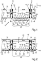
- Fig. 1 shows a schematic representation of an arrangement device 10 according to an embodiment of the invention. This serves to arrange a battery module 12 in at least a part 14 of a battery housing 16 with a cooling device 18 Fig. 1 Lower part 14 shown also have a suitable cover 20, which in Fig. 2 is shown. As in Fig. 1 shown, the battery housing 16 can be designed to accommodate a plurality of battery modules 12.
- the cooling device 18 has respective assigned module attachment areas 26.
- the respective module attachment areas 26, of which only one is provided with a reference number as an example here, are separated from one another by transverse webs 28. These transverse webs 28 run perpendicular to the cooling device 18.
- the battery housing 16 in particular its lower part 14, has respective insertion openings 30. After the battery modules 12 have been installed in the battery housing lower part 14, these insertion openings 30 can be closed by the cover 20 of the battery housing 16.
- the battery housing 16 can be designed at least in part as an extruded aluminum construction.
- Thermally conductive component 36 for example a thermal paste or gap filler.
- Such a heat-conducting component 36 should ideally be arranged as a layer as thin as possible with a height that is as constant as possible between the battery modules 12 and the cooling device 18.
- the cooling device In order to be able to achieve such a thin layer, very high contact forces are required for pressing the battery modules 12 onto this heat-conducting component 36 in the respective module attachment areas 26, which are for example in the range of 25 N / cm 2 .
- the cooling device In order to enable a homogeneous distribution of this heat-conducting component 36 at the same time, the cooling device must additionally be prevented from bending in the central areas of the respective module mounting areas 26. At the same time, it is advantageous if the cooling device 18 can be made as light as possible, ie with a low weight.
- this counter-holding device 38 again comprises several Support elements 40, which support the cooling device 18 on a second side 42, which lies opposite the first side 32 and faces away from the respective insertion openings 30.
- the battery modules 12 can be arranged particularly efficiently in the battery housing 16.
- a predetermined amount of heat-conducting component 36 can therefore first be introduced into the respective module mounting areas 26, in particular onto the first side 32 of the cooling device 18.
- the respective battery modules 12 can then be placed onto the respective module mounting areas 26, in particular onto the heat-conducting component 36 , be put on.
- the respective battery module 12 can also be used first and then the heat-conducting component 36 can be injected, in particular between the battery module 12 and the cooling device 18. Then the battery modules 12 are pressed against the heat-conducting component 36 in a pressing direction R running in the direction of the cooling device 18, and in particular against the cooling device 18 pressed.
- the counter-holding device 38 advantageously makes it possible to provide a counterforce, ie counter to the pressing direction R, so that a curvature of the cooling device 18 in the module mounting area 26 is prevented in the pressing direction R.
- the support elements 40 are arranged such that they only contact the cooling device 18 in the intermediate regions 24 for support.
- the contact pressure acting in the pressing direction R can advantageously be introduced into the respective support elements 40 via these intermediate regions 24.
- the pressure on the walls of the cooling channels 22 correspondingly decreases. This in turn enables the cooling device 18 to be made thin-walled and thus lighter in terms of weight, without having to accept the risk of possible elastic or plastic deformation in the area of the cooling channels 22.
- the arrangement device 10 furthermore has a pressing tool 44, by means of which the pressing force directed in the pressing direction R is exerted on the battery modules 12.
- a pressing tool 44 by means of which the pressing force directed in the pressing direction R is exerted on the battery modules 12.
- the housing of these battery modules 12 has at least on two opposite sides, and preferably all the way round, a flange 46, to which the pressing force 44 is applied by means of the pressing tool 44 for pressing the battery modules 12 on .
- the arrangement device 10 can be removed or the battery housing part 14 with the battery modules 12 can be removed from the arrangement device 10, and subsequent assembly steps can be provided to provide the final battery arrangement, in particular a high-voltage battery.
- This battery arrangement is in Fig. 2 shown schematically.
- the individual battery modules 12 can also be fastened to the battery housing 16, for example on the transverse webs 28, for example screwed to them, and a cover 20 of the battery housing 16 can also be placed on the battery housing lower part 14 and fastened thereon.
- the battery housing 16 containing the battery modules 12 can also optionally be mounted on an underride guard 48.
- the battery arrangement is to be arranged in the underbody area of a motor vehicle, since such an underride protection 48 protects the battery modules 12 and the other components of this battery arrangement from stone chips and other environmental influences.
- Spacer elements which in this example are designed as trapezoidal sheets 50, can also be arranged between the underride guard 48 and the battery housing 14.
- FIG. 3 shows an illustration of a method for arranging a battery module 12 in a battery housing 16 or its lower part 14 in different chronologically successive stages of pressing according to a further exemplary embodiment of the invention.
- the battery module 12 is arranged in the lower battery housing part 14 by means of an arrangement device 10, which in turn comprises a counter-holding device 38 with a support element 40. and again the pressing tool 44 for pressing the battery module 12 onto the heat-conducting component 36 in the module attachment area 26 of the cooling device 18.
- the counter-holding device 38 or at least part of it, for example the support element 40 is in contrast to the example Fig.
- a predetermined amount of heat-conducting component 36 can again be applied to the cooling device 18 in the relevant module mounting area 26, in particular in a central area, as in FIG Fig. 3 shown.
- the battery module 12 is placed on the heat-conducting component 36 and pressed onto the heat-conducting component 36 in the pressing direction R by means of the pressing tool 44.
- a counterforce i.e.
- the support element 40 While the battery module 12 is pressed against the cooling plate 18 and the heat-conducting component 36 located thereon, the support element 40 is also moved in the pressing direction R, but in such a way that a counterforce is also applied to the cooling device 18 against the pressing direction R by this supporting element 40.
- the movement of the support element 40 reduces the curvature of the cooling plate 18, as in FIG Fig. 4 shown, and the heat-conducting component 36 is distributed and is pressed out of the central region of the module attachment region 26.
- the movement of the support element 40 in the pressing direction R is in 3 to 5 illustrated by the respective distances d1, d2 and d3. These represent the distances between a reference point of the support element 40, in this example its underside, and a reference point of the transverse webs 28, whereby by moving the support element 40 this distance d1, d2, d3 also increases, ie the distance d1 is smaller than that Distance d2, which in turn is smaller than distance d3.
- the flanges 46 arranged on the module housing of the battery module 12 rest on the transverse webs 28 and the cooling device 18 is in the flat, planar state. In this state, the heat-conducting component 36 is also distributed uniformly and homogeneously over the entire module mounting area 26.
- a plurality of support elements 40 can in turn be provided per module attachment area 26.
- the counter-holding device 38 can, for example, also be at least partially deformable and / or elastic, and / or comprise a pneumatic and / or hydraulic system, for example an air bellows system or the like.
- a pneumatic and / or hydraulic system for example an air bellows system or the like.
- the in Fig. 1 the counter-holding device shown can be provided for supporting the cooling device 18 and can also be designed to be movable.
- the examples show how the invention provides an arrangement device and a method which enable a particularly efficient configuration of a battery arrangement and a particularly efficient connection of battery modules to a cooling device.
- this allows a particularly small and uniform layer thickness or layer thickness of the gap filler to be set in a particularly advantageous manner.
Landscapes
- Chemical & Material Sciences (AREA)
- Chemical Kinetics & Catalysis (AREA)
- Electrochemistry (AREA)
- General Chemical & Material Sciences (AREA)
- Engineering & Computer Science (AREA)
- Manufacturing & Machinery (AREA)
- Battery Mounting, Suspending (AREA)
- Secondary Cells (AREA)
Priority Applications (1)
| Application Number | Priority Date | Filing Date | Title |
|---|---|---|---|
| PL19188817T PL3627585T3 (pl) | 2018-09-21 | 2019-07-29 | Sposób wprowadzenia co najmniej jednego modułu akumulatora w co najmniej jedną część obudowy akumulatora i urządzenie wprowadzające |
Applications Claiming Priority (1)
| Application Number | Priority Date | Filing Date | Title |
|---|---|---|---|
| DE102018216113.5A DE102018216113A1 (de) | 2018-09-21 | 2018-09-21 | Verfahren zum Anordnen zumindest eines Batteriemoduls in zumindest einem Teil eines Batteriegehäuses und Anordnungsvorrichtung |
Publications (3)
| Publication Number | Publication Date |
|---|---|
| EP3627585A2 true EP3627585A2 (fr) | 2020-03-25 |
| EP3627585A3 EP3627585A3 (fr) | 2020-04-29 |
| EP3627585B1 EP3627585B1 (fr) | 2021-05-19 |
Family
ID=67514324
Family Applications (1)
| Application Number | Title | Priority Date | Filing Date |
|---|---|---|---|
| EP19188817.1A Active EP3627585B1 (fr) | 2018-09-21 | 2019-07-29 | Procédé d'agencement d'au moins un module de batterie dans au moins une partie d'un boitier de batterie et dispositif d'agencement |
Country Status (5)
| Country | Link |
|---|---|
| US (1) | US11121424B2 (fr) |
| EP (1) | EP3627585B1 (fr) |
| CN (1) | CN110943189B (fr) |
| DE (1) | DE102018216113A1 (fr) |
| PL (1) | PL3627585T3 (fr) |
Cited By (2)
| Publication number | Priority date | Publication date | Assignee | Title |
|---|---|---|---|---|
| DE102020116587A1 (de) | 2020-06-24 | 2021-12-30 | Thyssenkrupp Ag | Gegenhaltevorrichtung und Verfahren zum Kontaktieren und Gegenhalten eines Batteriewannenbodens |
| EP4258423A1 (fr) * | 2022-04-04 | 2023-10-11 | Mazda Motor Corporation | Dispositif de gestion de température d'unité de batterie |
Families Citing this family (8)
| Publication number | Priority date | Publication date | Assignee | Title |
|---|---|---|---|---|
| DE102019201077B4 (de) | 2019-01-29 | 2026-07-02 | Audi Ag | Batteriemontageverfahren zum Bereitstellen einer Batterieanordnung |
| DE102020109679B4 (de) * | 2020-04-07 | 2024-02-29 | Lisa Dräxlmaier GmbH | Kraftmessmodul zum erfassen einer kraft und verfahren zum bestimmen einer kraft |
| DE102020111825B3 (de) * | 2020-04-30 | 2021-03-25 | Audi Aktiengesellschaft | Verfahren zum Einsetzen von Batteriemodulen in ein Batteriegehäuse und Einsetzvorrichtung |
| DE102020124738A1 (de) * | 2020-09-23 | 2022-03-24 | Audi Aktiengesellschaft | Verfahren und Stützvorrichtung zum Stützen eines Batteriegehäuses beim Einsetzen eines Batteriemoduls |
| DE102021109586B4 (de) * | 2021-04-16 | 2024-07-18 | Lisa Dräxlmaier GmbH | Verfahren zum Herstellen einer thermischen Schnittstelle zwischen einer Kontaktfläche und einer Aufnahmefläche |
| DE102022115357A1 (de) | 2022-06-21 | 2023-12-21 | Audi Aktiengesellschaft | Verfahren zum Injizieren einer Wärmeleitmasse in einen spaltförmigen Freiraum und Injektionsanordnung mit Druckabdeckung |
| DE102023120483A1 (de) | 2023-08-02 | 2025-02-06 | Dr. Ing. H.C. F. Porsche Aktiengesellschaft | Flüssigkeitsgekühlte Hochvolt-Traktionsbatterie |
| DE102024118110A1 (de) * | 2024-06-26 | 2025-12-31 | Audi Aktiengesellschaft | Verfahren zum Herstellen einer Traktionsbatterie für ein Kraftfahrzeug sowie Vorrichtung zur Herstellung einer Traktionsbatterie |
Citations (3)
| Publication number | Priority date | Publication date | Assignee | Title |
|---|---|---|---|---|
| DE102011052513A1 (de) | 2011-08-09 | 2013-02-14 | Rehau Ag + Co. | Batteriegehäuseteil zur Aufnahme einer Traktionsbatterie eines Elektrofahrzeugs und Verfahren zur Herstellung des Batteriegehäuseteils |
| DE102012214443A1 (de) | 2012-08-14 | 2014-02-20 | Robert Bosch Gmbh | Verspannen von Batteriezellen durch eine bombierte Ausgestaltung des Batteriegehäuses |
| DE102013207535A1 (de) | 2013-04-25 | 2014-10-30 | Lisa Dräxlmaier GmbH | Polverbindungsblech für eine Batterie |
Family Cites Families (8)
| Publication number | Priority date | Publication date | Assignee | Title |
|---|---|---|---|---|
| DE102009058070A1 (de) * | 2009-12-14 | 2011-06-16 | Behr Gmbh & Co. Kg | Kühlvorrichtung für ein Batteriemodul |
| DE102010038600B4 (de) * | 2010-07-29 | 2024-11-07 | Bayerische Motoren Werke Aktiengesellschaft | Vorrichtung zur Spannungsversorgung mit einer Kühlanordnung |
| DE102010038681A1 (de) * | 2010-07-30 | 2012-02-02 | Bayerische Motoren Werke Aktiengesellschaft | Vorrichtung zur Spannungsversorgung mit einer Kühlanordnung |
| FR2986190B1 (fr) * | 2012-02-01 | 2015-02-27 | Plastic Omnium Cie | Boitier pour module electrique d'un pack batterie pour vehicule automobile et pack batterie pour vehicule automobile |
| DE102016201726A1 (de) * | 2016-02-04 | 2017-08-10 | Mahle International Gmbh | Batterieanordnung |
| DE102016216050B4 (de) * | 2016-08-25 | 2023-11-09 | Volkswagen Aktiengesellschaft | Batteriebaugruppe und Fahrzeug mit einer derartigen Batteriebaugruppe |
| FR3060206A1 (fr) * | 2016-12-09 | 2018-06-15 | Valeo Systemes Thermiques | Dispositif de stockage d'energie electrique pour vehicule automobile et piece rapportee formant une partie du boitier d’un tel dispositif de stockage d’energie |
| US10333116B2 (en) * | 2017-01-11 | 2019-06-25 | Memory Protection Devices, Inc. | Top loading battery holder |
-
2018
- 2018-09-21 DE DE102018216113.5A patent/DE102018216113A1/de not_active Withdrawn
-
2019
- 2019-07-29 EP EP19188817.1A patent/EP3627585B1/fr active Active
- 2019-07-29 PL PL19188817T patent/PL3627585T3/pl unknown
- 2019-08-26 US US16/550,540 patent/US11121424B2/en active Active
- 2019-09-20 CN CN201910890593.6A patent/CN110943189B/zh active Active
Patent Citations (3)
| Publication number | Priority date | Publication date | Assignee | Title |
|---|---|---|---|---|
| DE102011052513A1 (de) | 2011-08-09 | 2013-02-14 | Rehau Ag + Co. | Batteriegehäuseteil zur Aufnahme einer Traktionsbatterie eines Elektrofahrzeugs und Verfahren zur Herstellung des Batteriegehäuseteils |
| DE102012214443A1 (de) | 2012-08-14 | 2014-02-20 | Robert Bosch Gmbh | Verspannen von Batteriezellen durch eine bombierte Ausgestaltung des Batteriegehäuses |
| DE102013207535A1 (de) | 2013-04-25 | 2014-10-30 | Lisa Dräxlmaier GmbH | Polverbindungsblech für eine Batterie |
Cited By (3)
| Publication number | Priority date | Publication date | Assignee | Title |
|---|---|---|---|---|
| DE102020116587A1 (de) | 2020-06-24 | 2021-12-30 | Thyssenkrupp Ag | Gegenhaltevorrichtung und Verfahren zum Kontaktieren und Gegenhalten eines Batteriewannenbodens |
| DE102020116587B4 (de) | 2020-06-24 | 2022-03-03 | Thyssenkrupp Ag | Gegenhaltevorrichtung und Verfahren zum Kontaktieren und Gegenhalten eines Batteriewannenbodens |
| EP4258423A1 (fr) * | 2022-04-04 | 2023-10-11 | Mazda Motor Corporation | Dispositif de gestion de température d'unité de batterie |
Also Published As
| Publication number | Publication date |
|---|---|
| CN110943189A (zh) | 2020-03-31 |
| PL3627585T3 (pl) | 2021-10-11 |
| US20200099017A1 (en) | 2020-03-26 |
| EP3627585B1 (fr) | 2021-05-19 |
| US11121424B2 (en) | 2021-09-14 |
| DE102018216113A1 (de) | 2020-03-26 |
| EP3627585A3 (fr) | 2020-04-29 |
| CN110943189B (zh) | 2022-07-05 |
Similar Documents
| Publication | Publication Date | Title |
|---|---|---|
| EP3627585B1 (fr) | Procédé d'agencement d'au moins un module de batterie dans au moins une partie d'un boitier de batterie et dispositif d'agencement | |
| DE102018221988A1 (de) | Batteriegehäuse zur Aufnahme eines Batteriemoduls, Batteriemodulanordnung, Kraftfahrzeug und Verfahren zum Einbringen eines Wärmeleitelements in ein Batteriegehäuse | |
| DE102019201077A1 (de) | Batteriemontageverfahren zum Bereitstellen einer Batterieanordnung und Batterieanordnung | |
| WO2023099739A1 (fr) | Batterie | |
| DE102015204841A1 (de) | Befestigungsaufbau für einen elektrischen Energiespeicher | |
| DE102021118396A1 (de) | Modulgehäuseanordnung, Batteriemodul und Verfahren zum Verspannen eines Batteriemoduls | |
| DE112019005681T5 (de) | Batteriepack-Wasserableitsystem | |
| DE102018212550A1 (de) | Batterieanordnung und Kraftfahrzeug | |
| DE102019202156A1 (de) | Befestigungsanordnung, Toleranzausgleichsanordnung für eine Befestigungseinrichtung und Montageverfahren zum Befestigen eines Batteriemoduls an einer Kühlvorrichtung | |
| DE102018009432A1 (de) | Energieabsorptionselement und Verfahren zu dessen Herstellung | |
| DE102021118643A1 (de) | Verfahren zum Einbringen einer Wärmeleitmasse zwischen ein Batteriemodul und einen Gehäuseboden, Batterie und Kraftfahrzeug | |
| DE102018216833A1 (de) | Batteriegehäuseunterteil zur Aufnahme zumindest eines Batteriemoduls, Kraftfahrzeug und Verfahren zum Herstellen eines Batteriegehäuseunterteils | |
| DE102019211092A1 (de) | Verfahren zum Herstellen einer Batterievorrichtung für ein Kraftfahrzeug, Batterievorrichtung sowie Kraftfahrzeug mit einer Batterievorrichtung | |
| EP4178016A2 (fr) | Ensemble module de boîtier de batterie destiné à recevoir au moins une unité de batterie, en particulier une unité de batterie d'une batterie de traction, un véhicule pouvant être entraîné par moteur électrique | |
| DE102021133590A1 (de) | Batterieanordnung mit einem Distanzelement, Kraftfahrzeug und Verfahren zum Herstellen einer Batterieanordnung | |
| DE102022004064A1 (de) | Batteriemodul und Verfahren zu seiner Montage sowie Batterie | |
| DE102017111514B4 (de) | Gehäuse für einen Stapel aus elektrochemischen Einheiten zur Montage in einer elektrochemischen Vorrichtung | |
| DE102022211203A1 (de) | Batteriesystem für ein Kraftfahrzeug mit mindestens einem verklebten Element sowie Verfahren zum Lösen eines verklebten Elements eines Batteriesystems | |
| DE102021118644A1 (de) | Verfahren zum Einbringen einer Wärmeleitmasse zwischen ein Batteriemodul und einen Gehäuseboden, Batterie und Kraftfahrzeug | |
| DE102021129320A1 (de) | Batteriegehäuse, Energiespeicher und Verfahren zum Herstellen eines Energiespeichers | |
| DE102020127700A1 (de) | Befestigungsanordnung, Batteriegehäuse und Verfahren zum Befestigen eines ersten Bauteils an einem zweiten Bauteil | |
| DE102022200589B3 (de) | Batteriezellgehäuse sowie Anordnung einer Batteriezelle in einem Batteriegehäuse, insbesondere mit einem angrenzenden Kühlelement | |
| DE102014018709A1 (de) | Batterie für ein Kraftfahrzeug und Kraftfahrzeug | |
| DE102018216835A1 (de) | Batteriemodul und Kraftfahrzeug | |
| WO2024094433A1 (fr) | Ancrage de fixation pour une batterie, procédé permettant de produire une batterie, batterie et véhicule à moteur équipé d'une batterie de ce type |
Legal Events
| Date | Code | Title | Description |
|---|---|---|---|
| PUAI | Public reference made under article 153(3) epc to a published international application that has entered the european phase |
Free format text: ORIGINAL CODE: 0009012 |
|
| STAA | Information on the status of an ep patent application or granted ep patent |
Free format text: STATUS: THE APPLICATION HAS BEEN PUBLISHED |
|
| AK | Designated contracting states |
Kind code of ref document: A2 Designated state(s): AL AT BE BG CH CY CZ DE DK EE ES FI FR GB GR HR HU IE IS IT LI LT LU LV MC MK MT NL NO PL PT RO RS SE SI SK SM TR |
|
| AX | Request for extension of the european patent |
Extension state: BA ME |
|
| PUAL | Search report despatched |
Free format text: ORIGINAL CODE: 0009013 |
|
| AK | Designated contracting states |
Kind code of ref document: A3 Designated state(s): AL AT BE BG CH CY CZ DE DK EE ES FI FR GB GR HR HU IE IS IT LI LT LU LV MC MK MT NL NO PL PT RO RS SE SI SK SM TR |
|
| AX | Request for extension of the european patent |
Extension state: BA ME |
|
| RIC1 | Information provided on ipc code assigned before grant |
Ipc: H01M 10/6556 20140101ALI20200324BHEP Ipc: H01M 2/10 20060101AFI20200324BHEP |
|
| STAA | Information on the status of an ep patent application or granted ep patent |
Free format text: STATUS: REQUEST FOR EXAMINATION WAS MADE |
|
| 17P | Request for examination filed |
Effective date: 20200529 |
|
| RBV | Designated contracting states (corrected) |
Designated state(s): AL AT BE BG CH CY CZ DE DK EE ES FI FR GB GR HR HU IE IS IT LI LT LU LV MC MK MT NL NO PL PT RO RS SE SI SK SM TR |
|
| REG | Reference to a national code |
Ref country code: DE Ref legal event code: R079 Ref document number: 502019001445 Country of ref document: DE Free format text: PREVIOUS MAIN CLASS: H01M0002100000 Ipc: H01M0050200000 |
|
| GRAP | Despatch of communication of intention to grant a patent |
Free format text: ORIGINAL CODE: EPIDOSNIGR1 |
|
| STAA | Information on the status of an ep patent application or granted ep patent |
Free format text: STATUS: GRANT OF PATENT IS INTENDED |
|
| RIC1 | Information provided on ipc code assigned before grant |
Ipc: H01M 10/6556 20140101ALI20210210BHEP Ipc: H01M 50/20 20210101AFI20210210BHEP |
|
| INTG | Intention to grant announced |
Effective date: 20210305 |
|
| GRAS | Grant fee paid |
Free format text: ORIGINAL CODE: EPIDOSNIGR3 |
|
| GRAA | (expected) grant |
Free format text: ORIGINAL CODE: 0009210 |
|
| STAA | Information on the status of an ep patent application or granted ep patent |
Free format text: STATUS: THE PATENT HAS BEEN GRANTED |
|
| AK | Designated contracting states |
Kind code of ref document: B1 Designated state(s): AL AT BE BG CH CY CZ DE DK EE ES FI FR GB GR HR HU IE IS IT LI LT LU LV MC MK MT NL NO PL PT RO RS SE SI SK SM TR |
|
| REG | Reference to a national code |
Ref country code: GB Ref legal event code: FG4D Free format text: NOT ENGLISH |
|
| REG | Reference to a national code |
Ref country code: CH Ref legal event code: EP |
|
| REG | Reference to a national code |
Ref country code: DE Ref legal event code: R096 Ref document number: 502019001445 Country of ref document: DE |
|
| REG | Reference to a national code |
Ref country code: AT Ref legal event code: REF Ref document number: 1394880 Country of ref document: AT Kind code of ref document: T Effective date: 20210615 |
|
| REG | Reference to a national code |
Ref country code: IE Ref legal event code: FG4D Free format text: LANGUAGE OF EP DOCUMENT: GERMAN |
|
| REG | Reference to a national code |
Ref country code: LT Ref legal event code: MG9D |
|
| REG | Reference to a national code |
Ref country code: NL Ref legal event code: MP Effective date: 20210519 |
|
| PG25 | Lapsed in a contracting state [announced via postgrant information from national office to epo] |
Ref country code: LT Free format text: LAPSE BECAUSE OF FAILURE TO SUBMIT A TRANSLATION OF THE DESCRIPTION OR TO PAY THE FEE WITHIN THE PRESCRIBED TIME-LIMIT Effective date: 20210519 Ref country code: HR Free format text: LAPSE BECAUSE OF FAILURE TO SUBMIT A TRANSLATION OF THE DESCRIPTION OR TO PAY THE FEE WITHIN THE PRESCRIBED TIME-LIMIT Effective date: 20210519 Ref country code: FI Free format text: LAPSE BECAUSE OF FAILURE TO SUBMIT A TRANSLATION OF THE DESCRIPTION OR TO PAY THE FEE WITHIN THE PRESCRIBED TIME-LIMIT Effective date: 20210519 Ref country code: BG Free format text: LAPSE BECAUSE OF FAILURE TO SUBMIT A TRANSLATION OF THE DESCRIPTION OR TO PAY THE FEE WITHIN THE PRESCRIBED TIME-LIMIT Effective date: 20210819 |
|
| PG25 | Lapsed in a contracting state [announced via postgrant information from national office to epo] |
Ref country code: NO Free format text: LAPSE BECAUSE OF FAILURE TO SUBMIT A TRANSLATION OF THE DESCRIPTION OR TO PAY THE FEE WITHIN THE PRESCRIBED TIME-LIMIT Effective date: 20210819 Ref country code: LV Free format text: LAPSE BECAUSE OF FAILURE TO SUBMIT A TRANSLATION OF THE DESCRIPTION OR TO PAY THE FEE WITHIN THE PRESCRIBED TIME-LIMIT Effective date: 20210519 Ref country code: RS Free format text: LAPSE BECAUSE OF FAILURE TO SUBMIT A TRANSLATION OF THE DESCRIPTION OR TO PAY THE FEE WITHIN THE PRESCRIBED TIME-LIMIT Effective date: 20210519 Ref country code: SE Free format text: LAPSE BECAUSE OF FAILURE TO SUBMIT A TRANSLATION OF THE DESCRIPTION OR TO PAY THE FEE WITHIN THE PRESCRIBED TIME-LIMIT Effective date: 20210519 Ref country code: PT Free format text: LAPSE BECAUSE OF FAILURE TO SUBMIT A TRANSLATION OF THE DESCRIPTION OR TO PAY THE FEE WITHIN THE PRESCRIBED TIME-LIMIT Effective date: 20210920 Ref country code: IS Free format text: LAPSE BECAUSE OF FAILURE TO SUBMIT A TRANSLATION OF THE DESCRIPTION OR TO PAY THE FEE WITHIN THE PRESCRIBED TIME-LIMIT Effective date: 20210919 Ref country code: GR Free format text: LAPSE BECAUSE OF FAILURE TO SUBMIT A TRANSLATION OF THE DESCRIPTION OR TO PAY THE FEE WITHIN THE PRESCRIBED TIME-LIMIT Effective date: 20210820 |
|
| PG25 | Lapsed in a contracting state [announced via postgrant information from national office to epo] |
Ref country code: NL Free format text: LAPSE BECAUSE OF FAILURE TO SUBMIT A TRANSLATION OF THE DESCRIPTION OR TO PAY THE FEE WITHIN THE PRESCRIBED TIME-LIMIT Effective date: 20210519 |
|
| PG25 | Lapsed in a contracting state [announced via postgrant information from national office to epo] |
Ref country code: ES Free format text: LAPSE BECAUSE OF FAILURE TO SUBMIT A TRANSLATION OF THE DESCRIPTION OR TO PAY THE FEE WITHIN THE PRESCRIBED TIME-LIMIT Effective date: 20210519 Ref country code: EE Free format text: LAPSE BECAUSE OF FAILURE TO SUBMIT A TRANSLATION OF THE DESCRIPTION OR TO PAY THE FEE WITHIN THE PRESCRIBED TIME-LIMIT Effective date: 20210519 Ref country code: SK Free format text: LAPSE BECAUSE OF FAILURE TO SUBMIT A TRANSLATION OF THE DESCRIPTION OR TO PAY THE FEE WITHIN THE PRESCRIBED TIME-LIMIT Effective date: 20210519 Ref country code: CZ Free format text: LAPSE BECAUSE OF FAILURE TO SUBMIT A TRANSLATION OF THE DESCRIPTION OR TO PAY THE FEE WITHIN THE PRESCRIBED TIME-LIMIT Effective date: 20210519 Ref country code: DK Free format text: LAPSE BECAUSE OF FAILURE TO SUBMIT A TRANSLATION OF THE DESCRIPTION OR TO PAY THE FEE WITHIN THE PRESCRIBED TIME-LIMIT Effective date: 20210519 Ref country code: SM Free format text: LAPSE BECAUSE OF FAILURE TO SUBMIT A TRANSLATION OF THE DESCRIPTION OR TO PAY THE FEE WITHIN THE PRESCRIBED TIME-LIMIT Effective date: 20210519 Ref country code: RO Free format text: LAPSE BECAUSE OF FAILURE TO SUBMIT A TRANSLATION OF THE DESCRIPTION OR TO PAY THE FEE WITHIN THE PRESCRIBED TIME-LIMIT Effective date: 20210519 |
|
| REG | Reference to a national code |
Ref country code: DE Ref legal event code: R097 Ref document number: 502019001445 Country of ref document: DE |
|
| PLBE | No opposition filed within time limit |
Free format text: ORIGINAL CODE: 0009261 |
|
| STAA | Information on the status of an ep patent application or granted ep patent |
Free format text: STATUS: NO OPPOSITION FILED WITHIN TIME LIMIT |
|
| PG25 | Lapsed in a contracting state [announced via postgrant information from national office to epo] |
Ref country code: MC Free format text: LAPSE BECAUSE OF FAILURE TO SUBMIT A TRANSLATION OF THE DESCRIPTION OR TO PAY THE FEE WITHIN THE PRESCRIBED TIME-LIMIT Effective date: 20210519 |
|
| REG | Reference to a national code |
Ref country code: BE Ref legal event code: MM Effective date: 20210731 |
|
| 26N | No opposition filed |
Effective date: 20220222 |
|
| PG25 | Lapsed in a contracting state [announced via postgrant information from national office to epo] |
Ref country code: IS Free format text: LAPSE BECAUSE OF FAILURE TO SUBMIT A TRANSLATION OF THE DESCRIPTION OR TO PAY THE FEE WITHIN THE PRESCRIBED TIME-LIMIT Effective date: 20210919 Ref country code: LU Free format text: LAPSE BECAUSE OF NON-PAYMENT OF DUE FEES Effective date: 20210729 Ref country code: AL Free format text: LAPSE BECAUSE OF FAILURE TO SUBMIT A TRANSLATION OF THE DESCRIPTION OR TO PAY THE FEE WITHIN THE PRESCRIBED TIME-LIMIT Effective date: 20210519 |
|
| PG25 | Lapsed in a contracting state [announced via postgrant information from national office to epo] |
Ref country code: IT Free format text: LAPSE BECAUSE OF FAILURE TO SUBMIT A TRANSLATION OF THE DESCRIPTION OR TO PAY THE FEE WITHIN THE PRESCRIBED TIME-LIMIT Effective date: 20210519 Ref country code: IE Free format text: LAPSE BECAUSE OF NON-PAYMENT OF DUE FEES Effective date: 20210729 Ref country code: BE Free format text: LAPSE BECAUSE OF NON-PAYMENT OF DUE FEES Effective date: 20210731 |
|
| REG | Reference to a national code |
Ref country code: CH Ref legal event code: PL |
|
| PG25 | Lapsed in a contracting state [announced via postgrant information from national office to epo] |
Ref country code: LI Free format text: LAPSE BECAUSE OF NON-PAYMENT OF DUE FEES Effective date: 20220731 Ref country code: CH Free format text: LAPSE BECAUSE OF NON-PAYMENT OF DUE FEES Effective date: 20220731 |
|
| PG25 | Lapsed in a contracting state [announced via postgrant information from national office to epo] |
Ref country code: CY Free format text: LAPSE BECAUSE OF FAILURE TO SUBMIT A TRANSLATION OF THE DESCRIPTION OR TO PAY THE FEE WITHIN THE PRESCRIBED TIME-LIMIT Effective date: 20210519 |
|
| P01 | Opt-out of the competence of the unified patent court (upc) registered |
Effective date: 20230530 |
|
| PG25 | Lapsed in a contracting state [announced via postgrant information from national office to epo] |
Ref country code: HU Free format text: LAPSE BECAUSE OF FAILURE TO SUBMIT A TRANSLATION OF THE DESCRIPTION OR TO PAY THE FEE WITHIN THE PRESCRIBED TIME-LIMIT; INVALID AB INITIO Effective date: 20190729 |
|
| PG25 | Lapsed in a contracting state [announced via postgrant information from national office to epo] |
Ref country code: MK Free format text: LAPSE BECAUSE OF FAILURE TO SUBMIT A TRANSLATION OF THE DESCRIPTION OR TO PAY THE FEE WITHIN THE PRESCRIBED TIME-LIMIT Effective date: 20210519 |
|
| PG25 | Lapsed in a contracting state [announced via postgrant information from national office to epo] |
Ref country code: TR Free format text: LAPSE BECAUSE OF FAILURE TO SUBMIT A TRANSLATION OF THE DESCRIPTION OR TO PAY THE FEE WITHIN THE PRESCRIBED TIME-LIMIT Effective date: 20210519 |
|
| PG25 | Lapsed in a contracting state [announced via postgrant information from national office to epo] |
Ref country code: MT Free format text: LAPSE BECAUSE OF FAILURE TO SUBMIT A TRANSLATION OF THE DESCRIPTION OR TO PAY THE FEE WITHIN THE PRESCRIBED TIME-LIMIT Effective date: 20210519 |
|
| PGFP | Annual fee paid to national office [announced via postgrant information from national office to epo] |
Ref country code: PL Payment date: 20250630 Year of fee payment: 7 |
|
| REG | Reference to a national code |
Ref country code: AT Ref legal event code: MM01 Ref document number: 1394880 Country of ref document: AT Kind code of ref document: T Effective date: 20240729 |
|
| PGFP | Annual fee paid to national office [announced via postgrant information from national office to epo] |
Ref country code: DE Payment date: 20250731 Year of fee payment: 7 |
|
| PGFP | Annual fee paid to national office [announced via postgrant information from national office to epo] |
Ref country code: GB Payment date: 20250725 Year of fee payment: 7 |
|
| PG25 | Lapsed in a contracting state [announced via postgrant information from national office to epo] |
Ref country code: AT Free format text: LAPSE BECAUSE OF NON-PAYMENT OF DUE FEES Effective date: 20240729 |
|
| PGFP | Annual fee paid to national office [announced via postgrant information from national office to epo] |
Ref country code: FR Payment date: 20250729 Year of fee payment: 7 |
|
| PGFP | Annual fee paid to national office [announced via postgrant information from national office to epo] |
Ref country code: AT Payment date: 20260410 Year of fee payment: 5 |